

Page 1
Please read this manual carefully before operating your set and retain it for future reference.
P/NO : MFL63727101 (1005-REV00)
www.lg.com
Page 2

Property Statement
NOTE:
• Slight difference on OSD menu & photographs between manual & product display could be found.
• Prior notice will not be given for any amendments on this manual.
2
Page 3

Table of Contents
Property Statement . . . . . . . . . . . . . . . . . . . .2
Table of Contents . . . . . . . . . . . . . . . . . . . . . .3
To the Owner . . . . . . . . . . . . . . . . . . . . . . . . . .4
Safety Instructions . . . . . . . . . . . . . . . . . . . . .5
Air Circulation 6
Installing the Projector in Proper Position 6
Moving the Projector 6
Part Names and Functions . . . . . . . . . . . . . .7
Front 7
Back 7
Bottom 7
Rear Terminal 8
Top Control 9
Remote Control 10
Remote Control Battery Installation 11
Remote Control Operation Range 11
Installation. . . . . . . . . . . . . . . . . . . . . . . . . . .12
Positioning the Projector 12
Connecting to a Computer 13
Connecting to Video Equipment 14
Connecting to Component Video Equipment 15
Connecting the AC Power Cord 16
Basic Operation . . . . . . . . . . . . . . . . . . . . . .17
Turning On the Projector 17
Turning Off the Projector 18
How to Operate the On-Screen Menu 19
Menu Bar
Zoom and Focus Adjustment 21
Auto Setup Function 21
Keystone Correction 21
Sound Adjustment 22
Remote Control Operation 23
20
Computer Inputmputer Input . . . . . . . . . . . . . . . . . . . . . .25
Input Source Selection (Computer 1/2) 25
Computer System Selection 26
Auto PC Adjustment 27
Manual PC Adjustment 28
Image Mode Selection 29
Image Adjustment 30
Screen Size Adjustment 31
Video Input . . . . . . . . . . . . . . . . . . . . . . . . . .32
Input Source Selection (AV, S-Video, Component)
Video System Selection 33
Image Mode Selection 34
Image Adjustment 35
Screen Size Adjustment 36
32
Setting . . . . . . . . . . . . . . . . . . . . . . . . . . . . . .37
Setting 37
Information . . . . . . . . . . . . . . . . . . . . . . . . . .46
Input Source Information Display 46
Maintenance and Cleaning . . . . . . . . . . . . .47
WARNING indicator 47
Cleaning the Filters 48
Resetting the Filter Counter 48
Attaching the Lens Cap 49
Cleaning the Projection Lens 49
Cleaning the Projector Cabinet 49
Lamp Replacement 50
Lamp Model Replacement 51
Appendix . . . . . . . . . . . . . . . . . . . . . . . . . . . 52
Troubleshooting 52
Indicators and Projector Condition 55
Compatible Computer Specifications 56
RS232 Control Method 57-66
Configurations of Terminals
PIN Code Number Memo 67
LAN Control
MEMO 74
Technical Specifications
67
68-72
73Dimensions
75
Trademarks
Each name of corporations or products in this book is either a registered trademark or a trademark of its
respective corporation.
3
Page 4

To the Owner
Before installing and operating this rojector, read this
manual thoroughly.
This projector provides many convenient features and
functions. Operating the projector properly enables
you to manage those features and maintains it in good
condition for many years to come.
Please revise this manual for proper operation & cable
connections in case your projector does not work
properly, try solutions on Troubleshooting. If problems
still persist after following all operating instructions,
contact the dealer where you purchased the projector or
the service center.
The projector lamp is a consumable part. It's normal
the brightness reduces gradually and will be lower than
new one after working for a period of time. Please turn
on/off the projector strictly by the following the steps
as described in the Turn On the Projector and Turn
Off the Projector in this manual. Maintain and clean
regularly as per required specified in Maintenance and
Cleaning. Otherwise, the lamp residual heat may result
in the short life of the projector and the lamp grertly and
may damage them in a short time.
CAUTION
RISK OF ELECTRIC SHOCK
DO NOT OPEN
CAUTION: TO REDUCE THE RISK OF ELECTRIC
SHOCK, DO NOT REMOVE COVER (OR
BACK). NO USER-SERVICEABLE PARTS
INSIDE EXCEPT LAMP REPLACEMENT.
REFER SERVICING TO QUALIFIED
SERVICE PERSONNEL.
THIS SYMBOL INDICATES THAT DANGEROUS
VOLTAGE CONSTITUTING A RISK OF ELECTRIC
SHOCK IS PRESENT WITHIN THIS UNIT.
THIS SYMBOL INDICATES THAT THERE AR E
IMPORTANT OPERATING AND MAINTENANCE
INSTR UCT ION S IN THE OWN ER' S MANU AL
WITH THIS UNIT.
Safety Precaution
WARNING: • THIS PROJECTOR MUST BE EARTHED.
• TO REDUCE THE RISK OF FIRE OR
ELECTRIC SHOCK, DO NOT EXPOSE THIS
APPLIANCE TO RAIN OR MOISTURE.
– This projector produces intense light from the projection
lens. Do not stare directly into the lens, otherwise eye
damage could result. Be especially careful that children
do not stare directly into the beam.
– Install the projector in a proper position. Otherwise it
may result in fire hazard.
– Allowing the proper amount of space on the top, sides,
and rear of the projector cabinet is critical for proper air
circulation and cooling of the unit. The dimension shown
here indicate the minimum space required. If the
projector is to be built into a compartment or similarly
enclosed, these minimum distances must be
maintained.
– Do not cover the ventilation slot on the projector. Heat
build-up can reduce the service life of your projector,
and can also be dangerous.
SIDE and TOP Back
20cm
1m
50cm
1m
– If the projector is unused for an extended time, unplug
the projector from the power outlet.
– Do not project the same image for a long time. The
afterimage may remain on the LCD panels by the
characteristic of panel.
CAUTION
READ AND KEEP THIS OWNER'S MANUAL FOR LATER
USE.
4
DO NOT SET THE PROJECTOR IN GREASY, WET, OR SMOKY
CONDITIONS SUCH AS IN A KITCHEN TO PREVENT A
BREAKDOWN OR A DISASTER. IF THE PROJECTOR COMES
IN CONTACT WITH OIL OR CHEMICALS, IT MAY BECOME
DETERIORATED.
Page 5

Safety Instructions
All the safety and operating instructions should be read
before the product is operated.
Read all of the instructions given here and retain them
for later use. Unplug this projector from AC power supply
before cleaning. Do not use liquid or aerosol cleaners.
Use a damp cloth for cleaning.
Fo llow al l warnin gs and instru c tions marked on the
projector.
For added protection to the projector during a lightening
storm, or when it is left unattended and unused for long
periods of time, unplug it from the wall outlet. This will
prevent damage due to lightening and power line surges.
Do not expose this unit to rain or use near water... for
example, in a wet basement, near a swimming pool, etc...
Do not us e at t a chme n t s no t recomm e n d ed by the
manufacturer as they may cause hazards.
Do not place this projector on an unstable cart, stand,
or table. The projector may fall, causing serious injury
to a child or adult, and serious damage to the projector.
Us e only with a cart or stand rec o mmended by the
manufacturer, or sold with the projector. Wall or shelf
mounting should follow the manufacturer’s instructions,
an d sh ou ld us e a mo unt in g ki t ap pr ove d by the
manufacturers.
An appliance and cart combination
should be moved with care. Quic k
stops, excessive force, and uneven
surfaces may cause the appliance and
cart combination to overturn.
Slots and openings in the back and bottom of the cabinet
are provided for ventilation, to ensure reliable operation of
the equipment and to protect it from overheating.
The openings should never be covered with cloth or other
materials, and the bottom opening should not be blocked
by placing the projector on a bed, sofa, rug, or other
similar surface. This projector should never be placed
near or over a radiator or heat register.
This projector should not be placed in a built-in installation
such as a book case unless proper ventilation is provided.
Ne ver pu sh objects of any kind into this pr ojecto r
through cabinet slots as they may touch dangerous
voltage points or short out parts that could result in a
fire or electric shock. Never spill liquid of any kind on the
projector.
Do not install the projector near the ventilation duct of
air-conditioning equipment.
This projector should be operated only from the type
of power source indicated on the marking label. If you
are not sure of the type of power supplied, consult your
authorized dealer or local power company.
Do not overload wall outlets and extension cords as this
can result in fire or electric shock. Do not allow anything
to rest on the power cord. Do not locate this projector
where the cord may be damaged by persons walking on
it.
Do not attempt to service this projector yourself as
opening or removing Co v e rs may ex p o se you to
dangerous voltage or other hazards. Refer all servicing
to qualified service personnel.
Unplug this projector from wall outlet and refer servicing
to qualif ied se rvice personne l unde r the follow ing
conditions:
a. When the power cord or plug is damaged or frayed.
b. If liquid has been spilled into the projector.
c. If the projector has been exposed to rain or water.
d. If the projector does not operate normally by
following the operating instructions. Adjust only those
controls that are covered by the operating instructions
as improper adjustment of other controls may result
in damage and will often require extensive work by a
qualified technician to restore the projector to normal
operation.
e. If the projector has been dropped or the cabinet has
been damaged.
f. When the projector exhibits a distinct change in
performance-this indicates a need for service.
When replacement parts are required, be sure the
service technician has used replacement parts specified
by the manufacturer that have the same characteristics
as the original part. Unauthorized substitutions may
result in fire, electric shock, or injury to persons.
Upon completion of any service or repairs to this
projector, ask the service technician to perform routine
safety checks to determine that the projector is in safe
operating condition.
5
Page 6

Safety Instructions
Air Circulation
Openings in the cabinet are provided for ventilation. To
ensure reliable operation of the product and to protect it
from overheating, these openings must not be blocked
or covered.
CAUTION
Hot air is exhausted from the exhaust vent. When using
or installing the projector, the following precautions
should be taken.
– Do not put any flammable object or spray can near the
projector, hot air is exhausted from the air vents.
– Keep the exhaust vent at least 3’ (1 m) away from any
objects.
– Do not touch a peripheral part of the exhaust vent,
especially screws and metallic parts. These areas will
become hot while the projector is being used.
– Do not put anything on the cabinet. Objects put on the
cabinet will not only get damaged but also may cause
fire hazard by heat.
Cooling fans are provided to cool down the projector.
The fans’ running speed is changed according to the
temperature inside the projector.
Installing the Projector in Proper Position
Install the projector properly. Improper Installation may
reduce the lamp life and cause a fire hazard.
20°
20°
30°
30°
Do not tilt the projector more than 20
degrees from side to side.
Do not tilt the projector more than 30
degrees from above and below.
Do not point the projector up to project an
image.
Do not point the projector down to project
an image.
Do not put the projector on either side to
project an image.
Moving the Projector
When moving the projector, replace the lens cap and
retract adjustable feet to prevent damage to the lens and
cabinet.
When the projector is not in use for an extended period,
put it into a suitable case with the lens side up (supplied).
Exhaust Vents
(Hot air exhaust)
Air Intake
Vent
Air Intake Vent
CAUTION IN CARRYING OR TRANSPORTING
THE PROJECTOR
– Do not drop or bump the projector, otherwise damages
or malfunctions may result.
– When carrying the projector, use a suitable carrying
case.
– Do not transport the projector by courier or any other
transport service in an unsuitable transport case. This
may cause damage to the projector. For information
about transporting the projector by courier or any other
transport service, consult your dealer.
– Do not put the projector in a case before the projector is
cooled enough.
Exhaust
Vents
6
Page 7

Part Names and Functions
Front
Back
CAUTION
Hot air is exhausted from the exhaust vent. Do not put
heat-sensitive objects near this side.
Exhaust Vents
②
Air Intake Vent
③
Zoom Ring (Back)
④
Projection Lens
⑤
Lens Cap
*
Do not turn on a projector with lens cap attached. High
temperature from light beam may damage lens cap and
result in fire hazard.
⑥
CAUTION
Infrared Remote Receiver
Focus Ring (Front)
Top Controls and Indicators
Terminals and Connectors
Lamp Cover
Power Cord Connector
Speaker
Filterilterlter
Adjustable Feet
Bottom
**
Kensington Lock
*
** Security Slot
Anti theft chain may opt to attach this slot to deter theft of
the projector.
7
Page 8
Part Names and Functions
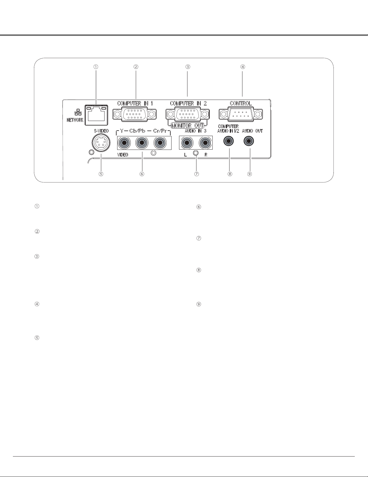
Rear Terminal
LAN Connection Terminal
Connect the LAN cable.
Computer 1 Input
Connect RGB output signal from a computer (page 13).
Computer 2 Input/Monitor Output/
–Connect RGB output signal from a computer (page 13)
–This terminal can be used to output the incomingte
analog RGB signal from Computer 1 Input to the other
monitor(page 13).
Control
Connect with computer by RS232 cable for PC
controls.
S-VIDEO IN-VIDEO IN
Connect the S-VIDEO output signal from video t
equipment to this jack
(page 14 ).
VIDEO IN/COMPONENT
Connect the component output signal to these
jacks (page 14).
AUDIO IN 3
Connect these jacks with audio output of ⑤ &
source (page 15).
Computer 1 / Computer 2 Audio Input Audio Input
Connect these jacks with audio output of
source(page 13).
Audio Output
Connect an external audio amplifier to this jack.
This jack recieves sources from AUDIO IN jack (
or ⑧) (page 14,15).
⑥
② &③
⑦
8
Page 9

Top Control
Part Names and Functions
⑤
①
②
③
④
①
LAMP REPLACE indicator
Lights yellow when the projection lamp reaches its
end of life (page 50).
②
WARNING indicator
–Lights red when the projector detects an
abnormal condition.
–Blinks red when the internal temperature of the
projector exceeds the operating range.
③
INPUT button
Select an input source (page 25, 32).
⑥
⑦
⑧
⑨
⑥
ON/STANDBY button
Turn the projector on or off (page 17, 18).
⑦
AUTO SETUP button
Correct vertical keystone distortion and adjust
computer display parameters such as Fine sync.,
Total dots, and Picture position.
⑧
–
Point
▲▼◄►
(VOLUME +/–) buttons
Select an item or adjust the value in the
On-Screen Menu.
Pan the image in the Digital Zoom +/- mode.
–
Adjust the volume level.
–
④
MENU button
Open or close the On-Screen Menu.
⑤
POWER indicator
–Lights red when the projector is in stand-by mode.
–Lights green during operations.
⑨
SELECT button
–Enter full menu from shortcut.
–Execute the selected item.
–Expand or compress the image in the Digital zoom
Mode.
9
Page 10

Part Names and Functions
Remote Control
①
⑦ Point ▲▼◄►▲▼◄►
②
button
- Select an item or adjust the value in the On-Screen Menu.
- Pan the image in the Digital zoom +/- mode.
③
④
⑤
⑥
⑦
⑧
⑨
⑩
⑪
⑫
⑬
⑭
① ON/STANDBY button
Turn the projector on or off (page 17,18).
② COMPUTER button
Select Computer 1 or Computer 2
input (page 25,32).
③ VIDEO button
Select the VIDEO inout source.
④ S-VIDEO button
Select the S-VIDEO input source.
⑤ KEYSTONE button
Correct keystone distortion.
⑮
⑧ FREEZE button
Freeze the picture on the screen.
⑯
⑰
⑱
⑲
⑨ Auto Set button
Correct vertical keystone distortion and adjust computer display
parameters such as Fine sync, Total dots, and Picture position.
⑩ TIMER button
Operate the timer function.
⑪
MUTE button.
Mute the sound.
⑫ ZOOM ▲▼ button
Zoomom in and out the images.
⑬ VOLUME +/- button
Adjust the volume level
⑭ PATTERN button
Test interior display signal
⑮ COMPONENT button
Select the COMPONENT input source.
⑯ DISPLAY button
Show cuow current information.
⑰ MENU button
Open or close menu.
⑱ SELECT button
–Execute the selected item.
–Expand or compress iamges in Digital zoom mode.
⑲ BLANK button
Temporarily shadow On-Screen images.
⑳
LAMP button
Select a lamp mode.
⑥ TERMINAL button
Enable the Computer IN 2 as Input
or output
NOTE:
To ensure safe operation, please observe
the following precautions:
– Do not bend, drop, or expose the remote
control to moisture or heat.
– For cleaning, use a soft dry cloth. Do
not apply benzene, thinner, spray, or any
chemical material.
10
16:9 button
Select 16:9 On-Screen Display.
4:3 button
Select 4:3 On-Screen Display.
IMAGE MODE button
Select the image mode.
INFO. button
Show lamp information etc.
Page 11

Remote Control Battery Installation
Part Names and Functions
Open the battery
1 2 3
compartment lid.
Install new batteries
into the compartment.
Two AAA size batteries
For correct polarity
(+ and –), be sure
battery terminals are
in contact with pins in
compartment.
To ensure safe operation, please observe the following precautions:
● Use two (2) AAA or LR03 type alkaline batteries.
● Always replace batteries in sets.
● Do not use a new battery with a used battery.
● Avoid contact with water or liquid.
● Do not expose the remote control to moisture or heat.
● Do not drop the remote control.
● If the battery has leaked on the remote control, carefully wipe the case clean and install new batteries.
● Risk of an explosion if battery is replaced by an incorrect type.
● Dispose of used batteries according to the instructions or your local disposal rule or guidelines.
Remote Control Operating Range
Replace the
compartment lid.
Point the remote control toward the projector (Infrared
Remote Receiver) when pressing the buttons. Maximum 5
metres and 60 degrees in front of the projector.
Adjustable Feet
Projection angle can be adjusted up to 10.0 degrees with
the adjustable feet.
Lift the front of the projector and press the feet lock latches
on both side of the projector.
Release the feet lock latches to lock the adjustable feet and
rotate the adjustable feet to a proper height, and tilt.
30°
30°
5 m
Remote Control
Keystone distortion can be adjusted automatically with the
Auto setup function or manually by using the remote control
or the menu operation.
Feet Lock Latches
Adjustable Feet
11
Page 12

Installation
Positioning the Projector
For projector positioning, see the figures below. The projector should be set perpendicularly to the plane of the
screen.
NOTE:
• The brightness in the room has a great influence on picture quality. It is recommended to limit ambient
lighting in order to obtain the best image.
• All measurements are approximate and may vary from the actual sizes.
BX27C-SL / BX30C-SL
10.752 m
8.952 m
5.96 m
1.172 m
40”
2.967 m
32”
4.464 m
80”
160”
120”
240”
(W x H) mm
4 : 3
( )
( )
40"
813 x 610
1.172m
1.411 m
100"
2032 x 1524
2.967 m
3.567 m
150"
3048 x 2286
4.464 m
5.363 m
4064 x 3048
200"
5.96 m
7.159 m
300"
6096 x 4572
8.952 m
10.752 m
12
Page 13

Connecting to a Computernecting to a Computer
Cables used for connection
• VGA Cables (Mini D-sub 15 pin) *
• Audio Cables
(*VGA Cable is supplied; other cables are not supplied with the projector.)
Installation
Audio Output
Audio
cable
Monitor Output
VGA
cable
Computer 1
Input
Computer 1/2
Audio Input
Monitor Output
VGA
cable
Computer 2 2
Input
Monitor Input
VGA
cable
Monitor
Output
External Audio Equipment
Audio Input
Audio cable
Audio Output
Note:
Input sound to the Computer 1/ Computer 2 AUDIO IN terminal
•
when using the COMPUTER IN 2 / MONITOR OUT and the
COMPUTER IN 1 terminal as input.
When the AUDIO OUT is plugged-in, the projector's built-in
•
speaker is not available.
Unplug the power cords of both the
project or an d ext ern al eq uipment
from the AC outlet before connecting
cables.
13
Page 14

Installation
Connecting to Video Equipment
Cables used for connection
• Video and Audio Cable (RCA x 3)
• S-VIDEO Cable
• Audio Cable
(Cables are not supplied with the projector. )
External Audio Equipment
S-VIDEO Output-VIDEO OutputIDEO Output
S-VIDEO-VIDEO
cable
S-VIDEO-VIDEO
Video & Audio Output
Audio & Video
cable
Video
Audio Input
RLLVideo
Audio Input
Audio
cable
Audio Output
NOTE:
When the AUDIO OUT is plugged-in, the projector's built-
in speaker is not available.
14
Unplug the power cords of both the
project or an d ext ern al eq uipment
from the AC outlet before connecting
cables.
Page 15

Connecting to Component Video Equipment
Cables used for connection
• Audio Cables
• Component Cable
• Component Cable
(Cables are not supplied with this projector.)
Installation
RGB Output
Scart-VGA
cable
Component Input
Component Video Output
(Y, Pb/Cb, Pr/Cr)
Component
cable
Component Input
Audio Output
Audio
cable
Audio
Input
External Audio Equipment
Audio Input
Audio
cable
Audio Output
NOTE:
When the AUDIO OUT is plugged-in, the projector's built-
in speaker is not available.
Unplug the power cords of both the
project or an d ext ern al eq uipment
from the AC outlet before connecting
cables.
15
Page 16

Installation
Connecting the AC Power Cord
This projector uses nominal input voltages of 100~240V
AC and it automatically selects the correct input
voltage. It is designed to work with single-phase power
systems having a grounded neutral conductor.
To reduce the risk of electrical shock, do not plug into
any other type of power system.
If you are not sure of the type of power being supplied,
consult your authorized dealer or service station.
Connect the projector with all peripheral equipment
before turning the projector on. (page 14-16)
CAUTION
The AC outlet must be near this equipment and must be easily
accessible.
Connect the AC power cord (supplied) to the
projector.
Note:
Unplug the AC power cord when the projector is not in use
for security reasons. When this projector is connected to an
outlet with the AC power cord, it is in Stand-by mode and
consumes a little electric power.
NOTE ON THE POWER CORD
AC power cord must meet requirement of the country where you use the projector.
Confirm the AC plug type with the chart below and proper AC power cord must be used.
If supplied AC power cord does not match your AC outlet, contact your sales dealer.
Projector side
To power cord connector
on your projector.
AC outlet side
Ground
To the AC outlet.
(100 - 240 V AC)
Remark
European and Korea
market
Chinese market
UK market
US market
16
NOTE:
● Inproper cable may influence product performance or even lead to eletric shock, fire and other accidents. Please use
original model cables as supplied for safety and best performance of product.
● Frequent cable types: AC power cable, various VGA cable, Audio cable, AV cable, RS232 cable etc.
Page 17

Basic Operation
Turning On the Projectorrning On the Projector
Complete peripheral connections (with a computer,
1
VCR, etc.) before turning on the projector.
Connect the projector's AC power cord into an AC
2
outlet. The POWER indicator lights red. Open the lens
cap.
Press the ON / STAND-BY button on the top control or
3
on the remote control. The POWER indicator lights
green and the cooling fans start to operate. The
preparation display appears on the screen and 30’s
countdown starts.
If the projector is locked with a PIN code, PIN code
4
input dialog box will appear. Enter the PIN code as
instructed on the next page.
NOTE:
• When the Logo select function is set to Off, the logo will
not be shown on the screen.
• When Off is selected in the Display function, Countdown and
logo will not be shown on the screen.
• During the countdown period, all operations are invalid.
Enter a PIN code
Use the Pointed ▲▼ buttons to enter a number. Press Point
► button to fix the number and move the curser to the next
box. The number changes to “”. If you fixed an incorrect
number, use the Point ◄ button to move the pointer to the
number you want to correct, and then enter the correct
number by pressing ▲▼ buttons.
Repeat this step to complete entering a three-digit number.
After entering the three-digit number, move the pointer to
Set. Press the SELECT button so that you can start to
operate the projector.
If you entered an incorrect PIN code, PIN code and the
number (
PIN code all over again. If there is none correct PIN code
input within 3 minutes,the projector will power off automatically.
) will turn red for a moment. Enter the correct
What is PIN code?
PIN code is a security code that allows the person who
knows it to operate the projector. Setting a PIN code
prevents unauthorized use of the projector.
A PIN code consists of a three-digit number. Refer to the
PIN code lock function in the Setting Menu on pages 43 for
locking operation of the projector with your PIN code.
0
Set
Select
CAUTION ON HANDLING PIN CODE
If you forget your PIN code, the
projector can no longer be started.
Take a special care in setting a
new PIN code; write down the
number in a column on page 67 of
this manual and keep it on hand.
If the PIN code is lost or forgotten,
consult your dealer orservice center.
17
Page 18

Basic Operation
Turning Off the Projector
Press the ON/STAND-BY button on the top control or
1
on the remote control, and Power off? appears on the
screen.
Press the ON/STAND-BY button again to turn off the
2
projector. The POWER indicator starts to blink red,
and the cooling fans keep running.
When the projector has cooled down enough, the
3
POWER indicator stops blinking and you can turn on
the projector.
TO MAINTAIN THE LIFE OF THE LAMP, ONCE
YOU TURN THE PROJECTOR ON, WAIT AT
LEAST FIVE MINUTES BEFORE TURNING IT
OFF.
Power off ?
Power off ? disappears after 4 seconds.
DO NOT OPERATE THE PROJECTOR
CONTINUOUSLY WITHOUT REST.
CONTINUOUS USE MAY RESULT IN
SHORTENING THE LAMP LIFE. TURN OFF THE
PROJECTOR AND LET STAND FOR ABOUT AN
HOUR IN EVERY 24 HOURS.
NOTE:
• When the On start function is set to On, the projector will be
turned on automatically by connecting the AC power cord to an
AC outlet
• The running speed of cooling fans is changed according to the
temperature inside the projector.
• Do not put the projector in a case before the projector is cooled
enough.
• If the WARNING indicator blinks or lights red, see “WARNING
indicator” on page 47.
• While the POWER indicator is blinking, the lamp is being
cooled down and the projector cannot be turned on. Wait until
the POWER indicator turns red to turn on the projector again.
• The fan rotation will terminate directly if the AC power cord is
unplugged immediately after the projector is turned off.
• The projector can be turned on after the POWER indicator
turns red. The waiting time to restart will be shortened when
the normal power-off processing for fan cooling is completed,
compared with the time the AC power cord is immediately
unplugged after the power-off.
18
Page 19

How to Operate the On-Screen Menu
Basic Operation
The projector can be adjusted or set via the On-Screen
Menu. The menus have been sorted as Menu, Menu
has a hierarchical structure, with a main menu that is
divided into submenus, which are further divided into other
submenus. For each adjustment and setting procedure,
refer to respective sections in this manual.
Top Control
Point buttons
*
SELECT button
MENU button
Stands for “menu” key of top control and remote control.
Remote Control
MENU button
Point buttons
SELECT button
Menu
Press the MENU button on the Top Control to display
1
Menu.
Press ▲▼ buttons to highlight or select a main menu
2
item. Press Point ► button or SELECT button to
access the submenu items.
Press ▲▼ buttons to select the desired
3
submenu item and press the SELECT button to set or
access the selected item.
Press Point ▲▼◄► button to adjust the setting or
4
switch between each option and press the SELECT
button to activate it and return to the submenu.
Press Point ◄ button to return to the main menu.
5
Press the MENU button to exit the On-Screen Menu.
Menu
19
Page 20

Basic Operation
Menu Bar
Main Menu
1
2
③
④
⑤
⑥
⑦
8
9
Sub-Menu
*
①
PC adjust
Select Fine sync ., Total dots, Horizontal, Vertical and Auto PC adj. to adjust the parameters to match with the PC input
signal format.
②
Screen
For computer source,
For video source,
③
Image select
For computer source, used to select an image mode from among Dynamic, Normal, Cinema, Blackboard(Green),
Colorboard or USER Image.
④
Image adjustment
For computer source, used to adjust computer image [Contrast, Brightness, Color temp., white balance (R/G/B), Sharpness
and Gamma].
For Video source, used to adjust picture image [Contrast, Brightness, Color, Tint, white balance (R/G/ B),
Sharpness, Gamma, Noise reduction and Progressive].
⑤
Input
Used to select an input source from Computer 1, Computer 2, Component, Video or S-video.
⑥
Sound
Used to adjust the volume or mute the sound.
image size is set in accordance with input signal format, Normal, 16:9, 4:3 or Digital Zoom +/-.
image size is set in Normal or 16:9.
Stands for “menu” key of top control and remote control.
Stands for “select” key of top control and remote control.
⑦
Setting
Used to set the projector's operating configurations.
⑧
Network
LAN function.
⑨
Information
Display relevant Information..
20
Page 21

Zoom and Focus Adjustment
Basic Operation
Rotate the Zoom Ring to zoom in and out.
Rotate the Focus Ring to adjust the focus of the image.
Auto Setup Function
Auto setup function is provided to automatically execute the
setting of Auto setup (includes Input search, Auto PC adj.
and Auto Keystone functions) in the setting menu by just
pressing the AUTO SETUP button on the top control or the
AUTO SET button on the remote control.
NOTES:
• Auto Keystone corrects vertical distortion only; it does
not correct horizontal distortion.
• Auto Keystone cannot work when Ceiling On.
• Perfect correction of the image distortion cannot be
ensured with the Auto setup function. If the distortion
cannot be corrected properly by pressing the AUTO
SETUP or AUTO SET button, adjust manually by
pressing the KEYSTONE button on the remote control
or selecting Keystone in the Setting menu.
••Fine sync., Total dots, Horizontal & Vertical position of
some computers cannot be fully adjusted with the Auto
PC Adjustment function. When the image is not provided
properly with this operation, manual adjustments are
required.
mark on if there is nothing to do of the key.
Focus Ring (Front)
Top Control
Remote Control
KEYSTONE button
Zoom Ring (Back)
Auto Set button
Point ▲▼ buttons
Point ▲▼ buttons
Auto Set button
Keystone Correction
If a projected picture still has keystone distortion after
pressing the AUTO SETUP button on the top control or the
AUTO SET button on the remote control, correct the image
manually as follows:
Press the KEYSTONE button on the remote control. The
Keystone dialog box appears. Use the
correct keystone distortion. The keystone adjustment can be
stored.
Reduce the upper width
with the Point
▲ button.
▲▼ buttons to
Reduce the upper width
with the Point ▼ button.
Keystone
• An arrow disappears at the maximum
correction.
• nonottubENOTSYEKehtsserpuoyfI
keystone adjustment will be canceled.
• The adjustable range is limited depending
on the input signal.
▲
▼
ehtelihweromecnolortnocetomereht
eht,deyalpsidgniebsixobgolaidenotsyek
21
Page 22

Basic Operation
Sound Adjustment
Direct Operation
Volume
Press the VOLUME+/– buttons on the top control or on the
remote control to adjust the volume.
Mute
Press the MUTE button on the remote control to select On
to temporarily turn off the sound. To turn the sound back
on, press the MUTE button again to select Off or press the
VOLUME +/– buttons. The Mute function is also effective for
the AUDIO OUT jack.
Top Control
VOLUME +/- buttons
Remote Control
MUTE button
VOL+ button
VOL- button
Menu Operation
Press the MENU button to display the Menu. Use
1
the Point ► button to select Sound. Press the SELECT
button to access the submenu items.
Press ▲▼ buttons and move the cursor to desired
2
submenu and press SELECT button.
Volume
Press Point ▲ button to turn up the volume; Press Point ▼
button to turn down the volume.
Mute
Press the SELECT button to switch the mute function On/
Off. When the sound is turned off, On is displayed. Press
the VOLUME +/– buttons again to turn the sound back on.
Sound Menu
22
Page 23

Basic Operation
Remote Control Operation
Using the remote control for some frequently used operations is advisable. Just pressing one of the buttons
enables you to make the desired operation quickly without calling up the On-Screen Menu.
COMPUTER 1/2, VIDEO, S-VIDEO and COMPONENT
buttons
Press the COMPUTER 1/2, VIDEO, S-VIDEO and
COMPONENT buttons on the remote control to select the
input source. Please information for details.
FREEZE button
Press the FREEZE button on the remote control to freeze
the picture on the screen. To cancel the Freeze function,
press the FREEZE button again or press any other button.
Information button
Display the Lamp counter
ZOOM buttons
Press the ZOOM ▲▼ buttons on the remote control to enter
to the Digital zoom +/– mode.
Remote Control
COMPUTER
button
VIDEO
button
FREEZE
button
Zoom ▲▼
buttons
S-video
button
COMPONENT
button
Point ▲▼
buttons
LAMP
button
Information
button
LAMP button
Press the LAMP button on the remote control to select the
lamp mode for changing the brightness on the screen.
Normal....... Normal brightness.
Eco............ Lower brightness reduces the lamp
power consumption and extends the
lamp life.
Note:
See the next page for the description of other
buttons.
23
Page 24

Basic Operation
BLANK button
Press the BLANK button on the remote control to black out
the image. To restore to normal, press the BLANK button
again or press any other button. The screen changes each
time you press the BLANK button as follows.
black out → normal → black out → normal →
......
TIMER button
Press the TIMER button on the remote control. The Timer
display 00:00 appears on the screen and the countdown
starts (00:00–59:59).
To stop the countdown, press the TIMER button. To cancel
the Timer function, press the TIMER button again.
IMAGE MODE button
Press the IMAGE MODE button on the Remote Control to
select a desired image mode of the screen.
Blank
BLANK disappears after 4 seconds if no
others button is pressed.
02:02
TIME display
BLANK button
TIMER button
16:9 button
4:3 button
Image Mode
button
PATTERN button
16:9 button
Choose 16:9 image size on screen displa
Image mode“Normal” will be chosen if 16:9 is unavailable.
y.
4:3 button
Choose 4:3 image size on screen display.
Image mode“Normal” will be chosen if 4:3 is unavailable.
Pattern button
Display of interior signal.
NOTE:
See the previous page for the
description of other buttons.
24
Page 25

Computer Inputmputer Input
Input Source Selection (Computer 1/Computer 2)
Direct Operation
Choose Computer 1 or Computer 2 by pressing the COMPUTER button of the Remote Control or on the Top
Control.
Top ControlRemote Control
COMPUTER button
Computer 1
INPUT button
Computer 1
Computer 2
MENU button
Menu Operation
Press the MENU button to display the On-Screen to display the On-Screen
1
Menu. Use the Point ▲▼ buttons to select Input and
then Press Point ► or the SELECT button.
Use the Point ▲▼ buttons to select Computer 1 or
2
Computer 2, and press SELECT button.
Computer 2
Component
Video
S-VIDEO-VIDEO
Input Menu
25
Page 26

Computer Inputmputer Input
Computer System Selectionmputer System Selection
This projector automatically tunes to various types of computers with its Multi-scan system and Auto PC
Adjustment. If a computer is selected as a signal source, this projector automatically detects the signal format
and tunes to project a proper image without any additional settings.
One of the following messages of the computer system menu may appear when:
Auto
-----
The projector cannot recognize the connected
signal conforming to the provided PC Systems.
Auto is displayed on the System Menu box and
the Auto PC Adjustment function works to display
proper images. If the image is not projected
properl
system menu show: Auto, it can’t be selected.
There is no signal input from the computer.
Check the connection between your computer
and the projector.(See “Troubleshooting” on
page 52.)
y, a manual adjustment is required. If the
Selecting Computer System Manually
Computer System Menu
The Computer System Menu
Selected system is displayed.
System can also be selected manually.
Press the MENU button to display the On-Screen
1
Menu. Use the Point ▲▼ buttons to select Input and
then Press Point ► or the SELECT button.
Use the Point ▲▼ buttons to select "System" and then
2
Press Point ► or the SELECT button.
Use the Point ▲▼ buttons to select the desired▲▼ buttons to select the desired buttons to select the desired
3
system and then press the SELECT button.
Press Menu button to Exit.
4
26
Page 27

Computer Inputmputer Input
Auto PC Adjustment
Auto PC Adjustment function is provided to automatically adjust Fine sync., Total dots, Horizontal, Vertical
to conform to your computer.
Menu Operation
Auto PC Adjustment
Press the MENU button on the Remote Control
1
to display the On-Screen Menu. Use the Point ▲▼
buttons to select PC adjust and then Press Point ►
or the SELECT button.
Press Point ▲▼ buttons to select “Auto PC Adj” and
2
then press SELECT button.
To store adjustment parameters
The adjusted parameters from the Auto PC Adjustment can
be stored in the projector.
NOTE:
• Fine sync., Total dots, Horizontal and Vertical position of
some computers cannot be fully adjusted with the Auto
PC Adjustment function. When the image is not provided
properly with this operation, manual adjustments are
required.
•
Auto PC adj. function is not suitable for the dark side image.
PC Adjust Menu
27
Page 28

Computer Inputmputer Input
Manual PC Adjustment
Some computers employ special signal formats which may not be tuned by Multi-scan system of this projector.
Manual PC Adjustment enables you to precisely adjust several parameters to match those signal formats. The
projector has five independent memory areas to store those parameters manually adjusted. It allows you to
recall the setting for a specific computer.
Press MENU button to display on screen menu.
1
Press Point ▲▼ buttons to choose PC Adjust button,
and then press SELECT button.
Use the Point ▲▼ buttons to select the desired item
2
and then press the SELECT button to display the
adjustment dialog box. Use the Point ◄► buttons to
adjust the setting value.
Fine sync
Use the Point ◄► buttons to adjust the value, eliminating a
flicker from the image displayed
Total dots
Use the Point ◄► buttons to adjust the number of total dots
in one horizontal period to match your PC image.
PC Adjust Menu
Horizontal
Use the Point ◄► buttons to adjust the horizontal picture position.
Vertical
Use the Point ◄► buttons to adjust the vertical picture position.
Reset:
To reset the adjusted data, you should choose the “Reset” and then
Click Yes when the dialogue box
ll adjusted vaa lue will return to the initial state.
Mode free:
To delete the saved data, you should select the Mode free and press ►
or Select. The mode to be deleted will be
highlighted. At the time,
Store:
To store the adjusted data, you should select Store, and press ►
or Select. Then move the cursor to select the saving
mode from the items 1-5. Finally click Select.
NOTE:
. When input signal is not included in the RGB Input SIGNAL TABLE on page 56,
some Menu of the Manual PC Adjustment function may be disabled.
. Some menu will be disabled, if the signal is above 140 MHz pixel clocks.
click Select.
appears for confirmation. After that,
28
Page 29

Image Mode Selection
Computer Inputmputer Input
Direct Operation
Select the desired image mode by pressing the IMAGE
MODE button on the remote control.
Menu Operation
Press the MENU button on the Remote Control
1
to display the On-Screen Menu. Use the Point ▲▼
buttons to select Image Select and then Press Point
► or the SELECT button.
Use the Point ▲▼ buttons to select the desired item
2
and then press the SELECT button.
Dynamic
This mode enhance the white-black contrast, you can get a
good effect even showed characters in a bright room.
Remote Control
IMAGE MODE
button
Normal
It is the preset mode of the projector. It balanced the brightness
and color, it is good for showing Computer signal to white screen.
Cinema
This mode limited the brightness, and more detail can be seen.
It is suitable for seeing a film in a dark environment.
Blackboard (Green)
For the image projected on a blackboard.
Th is mode help enhance the im age pro jected on a
blackboard. This is mainly effective on a green colored
board, not truly effective on a black colored board.
Colorboard
At the time of simple projection on the colored wall, you can
get the close color image to the color image projected on a
white screen by selecting the similar color to the wall color
from the preset four colors.
User Image
For viewing with the user preset image mode in the Image
Adjust Menu.
Image Select Menu
29
Page 30

Computer Inputmputer Input
Image Adjustment
Press the MENU button to display the On-Screen
1
Menu. Use the Point ▲▼ buttons to select▲▼ buttons to select buttons to select Image
Adjust and then Press Point ► or the SELECT button.► or the SELECT button. or the SELECT button.
Use the Point ▲▼ buttons select the desired item
2
and then press the SELECT button to display the
adjustment dialog box. Use the Point ◄► buttons to
adjust the setting value.
Contrast
Press Point ◄ button to decrease the contrast; Press Point
► button to increase the contrast.
Brightness
Press Point ◄ button to decrease the brightness; press
the Point ► button to increase the brightness
Color temp.
Use the Point ◄► buttons to select the desired Color temp.
level ( Low, Mid, or High).Or you change Color temperature
with adjusting Red,Green,Blue below:
Image Adjust Menu
Red
Press Point ◄ button to lighten red tone; Press Point. ►
button to deepen red tone.
Green
Press Point ◄ button to lighten green tone; Press Point ►
button to deepen green tone.
Blue
Press Point ◄ button to lighten blue tone; Press Point ►
button to deepen blue tone.
Sharpness
Press Point ◄ button to decrease the sharpness of the
image; Press Point ► button to increase the sharpness of
the image.
Gamma
Use the Point ◄► buttons to adjust the gamma value to
obtain a better balance of contrast.
NOTE:
• When White balance Red, Green or Blue is adjusted, Color temp. will change to USER.
• When Blackboard(Green) or Colorboard is selected in Image select, Color temp. will change to
Blackboard or Colorboard.
30
Page 31

Screen Size Adjustment
This projector has the picture screen resize function, which
enables you to customize the image size.
Press the MENU button to display the On-Screen
1
Menu. Use the Point ▲▼ buttons to select Screen and
then Press Point ► or the SELECT button.
Use the Point ▲▼ buttons select the desired item and
2
then press the SELECT button.
Normal
This function enables the same scale ratio of image as
signal source.
16:9
Display a scale ratio 16:9 normal video image.
4:3
Display a scale ratio 4:3 normal video image.
Computer Inputmputer Input
Screen Menu
16:9
4:3
For Zooming in and out the images
Digital zoom +
Select Digital zoom +. The On-Screen Menu disappears
and Zoom + appears. Press the SELECT button to expand
the image size.The image can be expanded upto 16 times
maximum.Use the Point ▲▼◄►buttons to pan the image.
The Panning function can work only when the image is larger
than the screen size.
A projected image can be also expanded by pressing the ▲
or the SELECT button on the remote control.
Digital zoom-
Select Digital zoom –. The On-Screen Menu disappears and
zoom – appears. Press the SELECT button to compress
image size. The image can be compressed into the 1/4 times
of its initial size.
The projected image can be also compressed by pressing
the ▼ or the SELECT button on the remote control.
To exit the Zoom +/– mode, press any button except
the ZOOM ▲▼ buttons and the SELECT buttons.
To return to the previous screen size, select a screen size
from the Screen Size Adjustment Menu or select an input
source from the Input Source Selection Menu again, or
adjust the screen size with the ZOOM ▲▼ buttons.
Remote Control
Point buttons
SELECT button
ZOOM ▲▼ button
NOTE:
Digital zoom doesn’t work when DCLK is higher than 140MHz (refer to the Timing table, page 56).
Digital zoom doesn’t work when the SCREEN is 4 : 3 .
31
Page 32

Video Input
Input Source Selection (VIDEO, S-video, Component)-video, Component), Component)Component))
Direct Operation
Choose Video, S-video or Component by pressing the INPUT button on the top control, or the VIDEO
button, the S-video button or the Component button on the remote control.
INPUT button
Top Control
Computer 1
Computer 2
COMPONENT
VIDEO
S-VIDEO-VIDEO
Menu Operation
Press the MENU button to display the On-Screen
1
Menu. Press Point ▲▼ buttons to select Input and
then press Point ► or the SELECT button.
Use the Point ▲▼ buttons to select either Video or
2
S-video and then press the SELECT button.
Remote Control
VIDEO button
VIDEO
COMPONENT button
COMPONENT
S-VIDEO button
S-VIDEO-VIDEO
Input Menu
COMPONENT
VIDEO
S-VIDEO-VIDEO
32
When the input source is coming from video
equipment connected to the COMPONENT
terminal with a Component Cable, select
Component.
When video input signal is connected to the
VIDEO jack, select Video.
When video input signal is connected to the
S- VIDEO jack, select S-video.
Page 33

Video System Selection
Video Input
Press the MENU button to display the On-Screen
1
Menu.Press Poi
then press Point
Press Point ▲▼ buttons to select COMPONENT,
2
VIDEO or S-VIDEO-VIDEO and then press SELECT button.SELECT button.
Press Point ▲▼ buttons to select System and then
3
press Point ►button or SELECT button. Press Point. Press PointPoint
▲▼ button select the desired system and then press
the SELECT button.
VIDEO or S-VIDEO
Auto
The projector automatically detects an incoming video
system, and adjusts itself to optimize its performance.
When Video System is PAL-M or PAL-N, select the system
manually.
PAL/SECAM/NTSC/NTSC4.43/PAL-M/PAL-N
If the projector cannot reproduce proper video image,
select a specific broadcast signal format from among PAL,
SECAM, NTSC, NTSC 4 .43, PAL-M, and PAL-N.
nt
▲▼ buttons to select Input and
► button or the
SELECT button..
VIDEO System Menu (Video or S-video)
COMPONENT
Auto
The projector automatically detects an incoming video
signal, and adjusts itself to optimize its perrformance.
COMPONENT VIDEO SIGNAL FORMAT
If the projector cannot reproduce proper video image, select
a specific component video signal format from among 480i,
576i, 480p, 576p, 720p, 1035i, and 1080i.
VIDEO System Menu (Component)
33
Page 34

Video Input
Image Mode Selection
Direct Operation
Select the desired image mode by pressing Image
Mode button on the Remote Control.
Menu Operation
Press the MENU button on the Remote Control
1
to display on screen menu. Press ▲▼ buttons to
select Image Select and then press Point ►button or
theSELECT button.
Use the Point ▲▼ buttons to select the desired item
2
and then press the SELECT button .
Dynamic
This mode enhance the white-black contrast, you can get a
good effect even showed characters in a bright room.
Normal
It is the preset mode of the projector. It balanced the brightness
and color, it is good for showing Computer signal to white screen.
Remote Control
Image Mode
button
Image Select Menu
Cinema
This mode limited the brightness, and more detail can be seen.
It is suitable for seeing a film in a dark environment.
Blackboard (Green)
For the image projected on a blackboard.
Th is mode help enhance the im age pro jected on a
blackboard. This is mainly effective on a green colored
board, not truly effective on a black colored board.
Colorboard
At the time of simple projection on the colored wall, you can
get the close color image to the color image projected on a
white screen by selecting the similar color to the wall color
from the preset four colors.
USER Image
For viewing with the user preset image mode in the Image
Adjust Menu.
34
Page 35

Image Adjustment
Video Input
Press the MENU button to display the On-Screen
1
Menu. Press Point ▲▼ button to select Image
Adjustment and then press Point ► button or SELECT
button.
Press Point ▲▼ buttons to select the desired item
2
and then press the SELECT button to display the
adjustment dialog box. Press Point ◄► button adjustbutton adjust
the setting value.
Contrast
Press Point ◄ button decrease Contrast; Press Point ►►
button increase Contrast.
Brightness
Press Point ◄ button decrease Brightness; Press Point
►button increase Brightness.button increase Brightness.
Color
Press Point ◄ button decrease the intensity of the color;
Press Point ► button increase the intensity of the color.► button increase the intensity of the color.button increase the intensity of the color.
Tint (only in NTSC)
Press Point ◄► button to adjust the tint value to get a◄► button to adjust the tint value to get abutton to adjust the tint value to get a
proper color balance.
Red
Press Point ◄ button lighten red tone; Press Point.► button
deepen red tone.
Image Adjust Menu
Green
Press Point ◄ button lighten green tone; Press Point.►
button deepen green tone.
Blue
Press Point ◄ button lighten blue tone; Press Point.►
button deepen blue tone.
Sharpness
Press Point ◄ button to decrease the sharpness of the
image; Press Point ► button to increase the sharpness of
the image.
Gamma
Use the Point ◄► buttons to adjust the gamma value to
obtain a better balance of contrast.
Noise reduction
Enable this item to reduce the snow interference and
achieve more smooth and clear image.
Progressive
An interlaced video signal can be displayed in progressive
mode. Select one of the following options.
Off ..........Disabled.
L1 .......... For an active picture.
L2 .......... For a still picture.
Film ........For watching a film. With this function, the
projector reproduces pictures faithful to the
original film quality.
35
Page 36

Video Input
Screen Size Adjustment
This projector has the picture screen resize function, which enables you to customize the image size.
Press Menu button on the Remote Control to display
1
on screen menu.Press ▲▼ buttons select Screen and
then press Point ►button or SELECT button.
Press ▲▼ buttons select the desired item and then
2
press the SELECT button.
Normal
This function enables the same scale ratio of image as
signal source.
16 : 9
Provide the image at the 16:9 wide screen ratio.
Screen Menu
16:9
36
Page 37

Setting
Setting
This projector has a Setting menu that allows you to set up
the other various functions described below.
Press Menu button on the Remote Control to display
1
on screen menu.Press ▲▼ buttons select the Setting
and then press Point ► button or SELECT button to
access the submenu items.
Use the Point ▲▼ buttons to select the desired item
2
and then press the Point ► or SELECT buttons to
access the selected item.
Use the Point ▲▼ buttons select the desired item and
3
then press the SELECT button.
Language
Language used in the On-Screen Menu is available in 17
languages.
Setting Menu
1. This function is used to change the position of the
On-Screen Menu. Select Menu position and press the SELECT
button.
2.Use the point ▲▼ to select the desired position:Upper left,
Upper right,Center,Lower left,Lower right.
37
Page 38

Setting
Auto setup
This function enables Input search, Auto Keystone correction
and Auto PC adjustment by pressing the AUTO SETUP button
on the top control or the AUTO SET button on the remote
control. Settings for those functions can be altered as follows:
Input search
This function detects the input signal automatically. When
a signal is found, the search will stop. Use the Point
buttons to select one of the following options.
Off .......... Input search will not work.
On...........Input search works under the following situation.
-When turning on the projector by pressing the
ON/STAND-BY button on the top control or the
remote control.
-When pressing the AUTO SET button on the
remote control.
-When pressing the AUTO SETUP button on the
top control.
-When the current input signal is cut off.
*If the Blank or Freeze function is active,cancel it to activate
the Input search. It is also unavailable when On-Screen menu is
displayed.
Auto PC adj.
On............. Press Auto Set button on the Top Control or
remote control to enable Auto PC Adjustment
function.
Off ........... Disables Auto PC Adjustment.
Auto Keystone
Off ........... Disables Auto Keystone.
Auto ........
Manual ........Activate this function by presing Auto Set on the
Top Control or the Remote Control.
Keystone Correction
This function is used to store or reset the keystone
correction when the
Point button or SELECT button to access the submenu items.
Use the Point ▲▼ buttons to switch between each option.
Store ...... ...... Keep the keystone correction even when
the AC power cord is unplugged.
Reset ............ Release the keystone correction when the
AC power cord is unplugged.
To correct keystone distortion, press the SELECT button.
Keystone appears on the screen. Use the Point ▲▼
buttons to correct keystone distortion.
.Always works and corrects keystone distortion
according to the projector's tilt.
▲
AC power cord is unplugged. Press
▲▼
Blue back
Select the background screen for when no input
signal is detected. Press the Point ▲▼ buttons
to switch between each option.
OnOn.............. Display Blue background
Off.............. Display Black background
NOTE:
• Only the last selected input source can be
detected.
• If the INPUT button on the top control or
the COMPUTER 1/2 buttons, VIDEO or
S-video or COMPONENT buttons on the
remote control is pressed during Input
search is in progress, Input search will stop
and go back to the previous input signal.
• Input Search, Auto PC Adj. and
Auto Keystone cannot be set Off at the
same time.
• Auto Keystone corrects vertical distortion
only, not correct horizontal distortion.
● please use the keystone manually when the
auto keystone can not adjust the image
square perfectly.
• Auto Keystone dosen’t work when the
Ceiling On.
• Perfect correction of the image distortion
cannot be ensured with the Auto setup
function. If the distortion is not corrected
properly by pressing the AUTO SETUP
or AUTO SET button, adjust manually by
pressing the KEYSTONE button on the
remote control or selecting Keystone in
the Setting menu.
• Fine sync., Total dots, Horizontal and
Vertical position of some computers
cannot be fully adjusted with the Auto PC
Adjustment function. When the image is
not provided properly with this operation,
manual adjustments are required.
•
mark on if there is nothing to do of
the auto set up key.
38
Page 39

Display
This function decides to display logo or not.
On............................ Show logo .
Off............................ Show the input image instead of the logo.
Logo (Logo and Logo PIN code lock settings)
This function allows you to customize the screen logo with Logo select, Capture, Logo PIN code lock
and Logo PIN code change functions.
NOTE:
When On is selected in the Logo PIN code lock function, Logo select and Capture functions cannot be
selected.
Logo select
This function decides on the starting-up display
from among following options.
User ........ Show the image you captured.
Default .... Show the factory-set logo.
Off ........... Show the countdown display only.
Setting
Capture
This function enables you to capture an image being projected to use it for a starting-up display.
Select Capture and press the SELECT button. A confirmation box appears and select Yes to capture the
projected image.
After capturing the projected image, go to the Logo select function and set it to User. Then the captured image
will be displayed when you turn on the projector next time.
Logo PIN code lock
This function prevents an unauthorized person from changing the screen logo.
Off ........... The screen logo can be changed freely from the Logo Menu.
On ........... The screen logo cannot be changed without a Logo PIN code.
If you want to change the Logo PIN code lock setting, press the SELECT button and the Logo PIN code
dialog box appears. Enter a Logo PIN code by following the steps below.
39
Page 40

Setting
Logo PIN code lock
Use the Point ▲▼ buttons to enter a number. Press the Point ► button to fix the number and move the red
frame pointer to the next box. The number changes to “*”. If you fixed an incorrect number, use the Point ◄
button to move the pointer to the number you want to correct, and then enter the correct number.
Repeat this step to complete entering a three-digit
number.
After entering the three-digit number, move the pointer to Set. Press the SELECT button so that you can start
to operate the projector.
If you entered an incorrect Logo PIN code, Logo PIN code and the number (***) will turn red for a moment.
Enter the correct Logo PIN code all over again.
Change the Logo PIN code lock setting
Use the Point ▲▼ buttons to switch On or Off, and then
press the SELECT button to make a choice.
Logo PIN code change
Logo PIN code can be changed to your desired threedigit number. Press the SELECT button to select Logo
PIN code change. Logo Pin code dialog box appears,
use the Point ▲▼ buttons to enter the correct code. The
New Logo PIN code input dialog box appears. Set a new
Logo PIN code, confirmation box appears, choose yes to
set the new Logo Pin code.
Be sure to note the new Logo PIN code and keep it on
hand. If you lost the number, you could no longer change
the Logo PIN code setting.
CAUTION:
WHEN YOU HAVE CHANGED THE LOGO PIN CODE,
WRITE DOWN THE NEW PIN CODE IN COLUMN OF
THE LOGO PIN CODE NO. MEMO ON PAGE 67, AND
KEEP IT SECURELY. IF THE LOGO PIN CODE IS LOST
OR FORGOTTEN THEN ITS SETTING CAN NO LONGER
BE CHANGED.
40
Page 41

Setting
Ceiling
This function is used to project the image from a ceilingmounted projector.
Off ...........Disable this function.
Auto ........The picuture will be reversed automatically according to the mounted postion.
On............The picture will be reversed.
Rear
This function is used to project the image from
rear of the screen.
Off ...........Disable this function.
On............Picture will be horizontally reversered.
Terminal
The COMPUTER IN 2/MONITOR OUT terminal on the back of the projector is switchable for computer input or
monitor output. (See page 8) Select Computer2 or Monitor Out with the Point ▲▼ buttons.
Computer 2................. ...Computer 2 Inputomputer 2 Input
Monitor Out ....................Monitor Output
Power management
For reducing power consumption as well as maintaining the lamp life, the Power management function turns off
the projection lamp when the projector is not operated and without signal for a certain period.
Select one of the following options:
Ready .................. When the lamp has been fully cooled down, the POWER indicator changes to green blinking.
In this condition, the projection lamp will be turned on very fast if the input signal is reconnected
or any
button on the top control or remote control is pressed.
Shut down .......... When the lamp has been fully cooled down, the power will be turned off.
Off ....................... Power management function is off.
Timer ................... If the input signal is interrupted and no button is pressed for more than 30 seconds, the timer
display with No signal appears. It starts the countdown until the lamp is turned off. Use the
Point ▲▼ buttons to set the Timer(1~30min.).
NOTE:
Factory default is Ready: 5 Min.
Power management
No signal
01 : 20
Time left before Lamp is off.
On Start
This function enables projector auto power on with detection connection with AC power cord.
41
Page 42

Setting
Standby mode
There are two standby modes in the projector.
Eco ...... Low power standby mode, in this mode, network, serial control and monitor output functions are disabled.
Normal ...... in this model, network, serial control and monitor output functions can be used.
Closed Caption
Closed Caption is a text version of the program sound or other information displayed on the screen.If the input
signal contains closed captions, you can turn on the feature and switch the channels. Press the Point ▲▼
buttons to select Off, CC1, CC2, CC3 or CC4.
NOTE:
The Closed Caption is available only under the situation below.
• When the input signal is NTSC of composite and S-video, and the system is set according to the signal or
set on Auto.
• The system must be set on NTSC or Auto in Video System Selection. (Page 33)
• The icon of Closed Caption is displayed in gray while it is not available.
• The Closed caption is unavailable when On-Screen menu and Timer are displayed.
Lamp Control
This function allows you to change brightness of the screen.
Normal ...... Normal brightness
Eco ............Lower brightness reduces the lamp power consumption and extends the lamp life.
Test Pattern
This function enables you to test & set interior signals.There are 12 types of test pattern: gray scale,
raster gray, color bar, red, green, blue, black, white, cross hatch.
Security (Key lock and PIN code lock)
This function allows you to use the Key lock and PIN code lock function to set the security for the projector
operation.
Key lock
This function locks the top control and remote control buttons to prevent operation by unauthorized persons.
Select Key lock and then press the SELECT button, and select the desired item by pressing the Point ▲▼
buttons.
If the top control accidentally becomes locked and you do not have the remote control nearby or there is
something wrong with your remote control, contact the dealer where you purchased the projector or the
service center.
(Except ON-STANDBY Key)
...........
...........
...........
Unlocked.
Lock the operation of the top control. To unlock, use the remote control.
Lock the operation of the remote control. To unlock, use the top control.
“ ”
“ ”
42
mark on while RC key pressed when RC locked.
mark on while top control pressed when top control locked.
Page 43

Setting
PIN code lock
This function prevents the projector from being operated by unauthorized persons and provides the following
setting options for security.
Off ............ Unlocked.
On ........... Enter the PIN code every time turning on the projector.
Whenever you change the PIN code lock setting or the PIN code (the three-digit number), you are required to
enter the PIN code. The “111” is set as the initial PIN code at the factory.
If you want to change the PIN code lock setting, Press the SELECT button and the PIN code dialog box
appears.
Enter a PIN code
Use the Point ▲▼ buttons to enter a number. Press the Point ► button to fix the number and move the red►
frame pointer to the next box. The number changes to “*”. If you fixed an incorrect number, use the Point ◄◄
button to move the pointer to the number you want to correct, and then enter the correct number.
Repeat this step to complete entering a three-digit number.
After entering the three-digit number, move the pointer to “Set.” Press the SELECT button so that you can
start to operate the projector.
If you entered an incorrect PIN code, PIN code and the number (***) will turn red for a moment. Enter the
correct PIN code all over again.
Change the PIN code lock setting
Use the Point ▲▼ buttons to select Off or On, and then press the SELECT button to make a choice.
PIN code change
The PIN code can be changed to your desired three-digit number. Press ▲▼ SELECT button to select PIN
code change. Pin code dialog box appears, use the Point ▲▼ buttons to enter the correct code. The New
PIN code input dialog box appears. Set a new PIN code.
CAUTION:
WHEN YOU HAVE CHANGED THE PIN CODE, WRITE DOWN THE NEW PIN CODE IN COLUMN OF
THE PIN CODE NO. MEMO ON PAGE 67, AND KEEP IT SECURELY. ONCE YOU ENTER WRONG PIN CODE,
THE PROJECTOR CAN NOT BE STARTED.
43
Page 44

Setting
Cooling fast
There are the following options in the cooling fans operation when the projector is turned off.
ON ... Faster and louder-sound than the normal operation, but it takes less time than off option.
OFF... Normal operation with about 60 seconds cooling times.
High land
This projector provides Fan control function in the "Setting" menu. Choose the running speed of cooling fans
from the following options according to the ground elevation where you use the projector.
Off......Normal speed.Set this function to "Off " when using the projector in non-high altitude environment.
On......Faster than Off mode.Select this mode when using the projector in high altitudes (above 2000m) where
the fans are weak in cooling effect.
Filter Counter
This function is used to set a frequency for the filter cleaning.
When the projector reached a specified time between cleanings, a Filter warning icon appears on the screen,
notifying the cleaning is necessary. After cleaning the filter, be sure to select RESET and set the timer. The Filter
warning icon will not turn off until the filter counter is reset.
Filter counter: The time of filter using after last cleaning.
Timer: The time between cleanings,100 hours,200 hours,300 hours.
Filter counter reset: Reset the filter counter.
Filter warning icon
44
Page 45

Factory default
This function returns all setting values except for the User
logo, PIN code lock, Logo PIN code lock, Lamp counter
and Filter counter to the factory default settings.
Setting
45
Page 46

Information
Input Source Information Display
The Information Menu is used for checking the status of the image signal being projected and the operation of
the projector.
Direct Operation
Press the DISPLAY. button on the remote control to display
information.
Menu Operation
Press Input on the Top Control and then press SELECT
button to display on screen menu. Press the Point ▲▼
buttons to select the Information. The Information Menu is
displayed.
See below for displayed information.
Input
The selected input source is displayed.
Remote Control
Display
button
H-sync freq .
The horizontal frequency of the input signal is displayed in
KHz, or - - - -KHz when no signal.
V-sync freq .
The vertical frequency of the input signal is displayed in Hz,
or - - - - Hz when no signal. Numbers of Hz doubles when
during Interlace.
Screen
The selected screen size is displayed.
Language
The selected language is displayed.
Lamp status
The selected lamp mode is displayed.
Lamp counter
The cumulative lamp operating time is displayed.
Power management
Off, Ready, or Shut down is displayed.
Key lock( Except ON-STANDBY key)
Display Off , Remote Control or the Projector .
46
Page 47

Maintenance and Cleaning
WARNING indicator
The Warning indicator shows the state of the function which protects the projector. Check the state of the
Warning indicator and the POWER indicator to take proper maintenance.
The projector is shut down and the warning
indicator is blinking red.
When the temperature inside the projector reaches a
certain level, the projector will be automatically shut down to
protect the inside of the projector. The POWER indicator is
blinking while the projector is being cooled down. When the
projector has cooled down enough (to its normal operating
temperature), it can be turned on again by pressing the ON/
STAND-BY button.
NOTE:
The WARNING indicator continues to blink even after
the temperature inside the projector returns to normal.
When the projector is turned on again, the WARNING
indicator stops blinking.
Then check the matters below:
– Did you provide appropriate space for the projector to be
ventilated? Check the installing condition to see if the air
vents of the projector are blocked.
– Has the projector been installed near an Air-Conditioning/
Heating Duct or Vent? Move the installation of the
projector away from the duct or vent.
– Is the filter clean? Clean the filter periodically.
Top Control
WARNING
blinking red
The projector is shut down and the warning
indicator lights red .
When the projector detects an abnormal condition, it is
automatically shut down to protect the inside of the projector
and the Warning indicator lights red. In this case, unplug the
AC power cord and reconnect it, and then turn the projector
on once again to verify operation. If the projector cannot be
turned on and the Warning indicator still lights red, unplug
the AC power cord and contact the service station.
CAUTION
DO NOT LEAVE THE PROJECTOR WITH THE
AC POWER CORD CONNECTED UNDER AN
ABNORMAL CONDITION. IT MAY RESULT IN
FIRE OR ELECTRIC SHOCK.
Top Control
WARNING
lights red
47
Page 48

Maintenance and Cleaning
Cleaning the Filters
Filter prevents dust from accumulating on the optical elements inside the projector. Should the filters become
clogged with dust particles, it will reduce cooling fans’ effectiveness and may result in internal heat buildup
and adversely affect the life of the projector. If a “Filter warning” icon appears on the screen, clean the filters
immediately. Clean the filters by following the steps below.
Turn off the projector, and unplug the AC power cord
1
from the AC outlet.
Turn the projector over and remove the filters.(Two
2
Filters available on this projector.
Clean the filters softly by using a brush.
3
Replace the filters properly. Make sure that the filters
4
are fully inserted to the projector.
Remove the
filters by using
your fingers to
curl around the
filter clipper.
CAUTION
Do not operate the projector with the filters
removed. Dust may accumulate on the optical
elements degrading picture quality.
Do not put anything into the air vents. Doing so
may result in malfunction of the projector.
Resetting the FilterCounter
Be sure to reset the Filter counter after cleaning or replacing
the filters.
Press the MENU button to display the On-Screen
1
Menu. Press ▲▼ buttons to select the Setting Menu
and then press the Point ► button or SELECT button.► button or SELECT button.button or SELECT button.
Press ▲▼ buttons to select Filter counter and then
2
press Point ► or SELECT button. Press ▲▼ buttons
to select Filter counter Reset and then press SELECT
button. The Filter counter Reset? appears. Select Yes
to continue.
Filter
RECOMMENDATION
we recommend avoiding dusty/smoky
environments when you operate the
projector. Usage in these environments
may cause poor image quality.
When using the projector under dusty or
smoky conditions, dust may accumulate
on a lens, LCD panels, or optical elements
inside the projector degrading the quality
of a projected image. When the symptoms
above are noticed, contact your authorized
dealer or service station for proper
cleaning.
48
Another confirmation dialog box appears, select Yes to
3
reset the Filter counter.
Page 49

Attaching the Lens Cap
When moving this projector or while not using it over an
extended period of time, attach the lens cap.
Attach the lens cap according to the following procedures.
Thread the string through the hole on the lens cap and
1
then tie a knot in the string to secure it in place.
To pass the other end of the string into the hole on the
2
top of the projector and pull at it.
Cleaning the Projection Lens
Unplug the AC power cord before cleaning.
Gently wipe the projection lens with a cleaning cloth that
contains a smal l amount of non-abrasive camera lens
cleaner, or use a lens cleaning paper or commercially
available air blower to clean the lens.
Maintenance and Cleaning
Avoid using an excessive amount of cleaner. Abrasive
cleaners, solvents, or other harsh chemicals might scratch
the surface of the lens.
Cleaning the Projector Cabinet
Unplug the AC power cord before cleaning.
Gently wipe the projector body with a soft dry cleaning cloth.
When the cabinet is heavily soiled, use a small amount of
mild detergent and finish with a soft dry cleaning cloth. Avoid
using an excessive amount of cleaner. Abrasive cleaners,
solvents, or other harsh chemicals might scratch the surface
of the cabinet.
When the projector is not in use, put the projector in
an appropriate carrying case to protect it from dust and
scratches.
49
Page 50

Maintenance and Cleaning
Lamp Replacement
When the projection lamp of the projector reaches its end
of life, the Lamp replacement icon appears on the screen
and LAMP REPLACE indicator lights yellow.Replace the
lamp with a new one promptly.The timing when the LAMP
REPLACE indicator should light is depending on the lamp
mode.
Lamp replacement
Lamp replacement icon
CAUTION
Allow a projector to cool for at least 45 minutes
before you open the Lamp Cover. The inside of
the projector can become very hot.
For continued safety, replace with a lamp of the
same type. Do not drop a lamp or touch a glass
bulb! The glass can shatter and may cause injury.
Top Control
LAMP REPLACE
indicator
CAUTION
CAUTION
When replacing the lamp because it has stopped illuminating, there is a possibility that the lamp may be
broken.
If replacing the lamp of a projector which has been installed on the ceiling, you should always assume that
the lamp is broken, and you should stand to the side of the lamp cover, not underneath it. Remove the
lamp cover gently. Small pieces of glass may fall out when the lamp cover is opened. If pieces of glass get
into your eyes or mouth, seek medical advice immediately.
Follow these steps to replace the lamp.
Unplug the AC power cord. Let the projector cool for at
1
least 45 minutes.
Loosen the screw and open the lamp cover.
2
Loosen the two (2) screws that secure the lamp. Lift
3
the lamp out of the projector by using the handle.
Replace the lamp with a new one and secure the two
4
(2) screws. Make sure that the lamp is set properly.
Close the lamp cover and secure the screw.
Connect the AC power cord to the projector and turn
5
on the projector.
50
Lamp Cover
Lamp
Cover
Screw
Screw
Handles
Lamp
Screw
Page 51

Maintenance and Cleaning
Lamp Model Replacement
ORDER REPLACEMENT LAMP
Replacement lamp can be ordered through your dealer. When ordering a projection lamp, give the following
information to the dealer:
●
Model No. of projector
● Replacement Lamp Type No. : 1300046500
: BX27C-SL / BX30C-SL
LAMP HANDLING PRECAUTIONS
This projector uses a high-pressure lamp which must be handled carefully and properly.
Improper handling may result in accidents, injury, or create a fire hazard.
● Lamp life may differ from lamp to lamp and according to the environment of use. There is no guarantee
of the same life for each lamp. Some lamps may fail or terminate their life in a shorter period of time
than other similar lamps.
● If the projector indicates that the lamp should be replaced, i.e., if the LAMP REPLACE indicator lights
up, replace the lamp with a new one IMMEDIATELY after the projector has cooled down.
(Follow carefully the instructions in the Lamp Replacement section of this manual.) Continuous use of
the lamp with the LAMP REPLACE indicator lighted may increase the risk of lamp explosion.
● A Lamp may explode as a result of vibration, shock or degradation as a result of hours of use as its
lifetime draws to an end. Risk of explosion may differ according to the environment or conditions in
which the projector and lamp are being used.
IF A LAMP EXPLODES, THE FOLLOWING SAFETY PRECAUTIONS SHOULD BE TAKEN .
If a lamp explodes, disconnect the projector’s AC plug from the AC outlet immediately. Contact an
authorized service station for a checkup of the unit and replacement of the lamp. Additionally, check
carefully to ensure that there are no broken shards or pieces of glass around the projector or coming out
from the cooling air circulation holes. Any broken shards found should be cleaned up carefully. No one
should check the inside of the projector except those who are authorized trained technicians and who
are familiar with projector service. Inappropriate attempts to service the unit by anyone, especially those
who are not appropriately trained to do so, may result in an accident or injury caused by pieces of broken
glass.
51
Page 52

Appendix
Troubleshooting
Before calling your dealer or service center for assistance, check the items below once again.
–Make sure you have properly connected the projector to peripheral equipment.
–Make sure all equipment is connected to AC outlet and the power is turned on.
–When the projector does not project an image from the connected computer, restart the computer.
Problem: – Solutions
No power – Plug the power cord of the projector into the AC outlet.
– See if the POWER indicator lights red.
– Wait until the POWER indicator stops blinking to turn on the
projector again. The projector can be turned on after
the POWER indicator turns red.
– Check the WARNING indicator. If the WARNING indicator lights red,
projector cannot be turned on.
– Check the projection lamp.
– Unlock the Key lock function for the projector.
The initial display is not shown – Make sure Off or Countdown off are not chosen at display
function.
The initial display is not same
as the default set .
Input signal switches automatically.
(or does not switch automatically)
when the projector is on and you press
the input button, an icon other than the
Lamp mode icon appears.
An icon other than Input mode or
Lamp mode icon appears .
Image is out of focus. – Adjust focus of the projector.
– Make sure User or Off are not chosen at Logo (select)
function.
– Make sure Input search function is adjusted properly.
– That is the Filter warning icon.
– That is the Lamp replacement icon or the Filter warning
icon.
– Provide proper distance between the projector and the projection
screen.
– Check the projection lens to see if it needs cleaning.
– Moving the projector from a cool to warm place may result in
moisture condensation on the projection lens. In such cases, leave
the projector off and wait until condensation evaporates.
Image is Left/Right reversed.
Image is Top/Bottom reversed.
Picture is not bright enough. – Check if the Contrast or Brightness are adjusted properly.
– Check the Ceiling/Rear function.
– Check the Top/Bottom (Ceiling) function.
– Check if Image mode is selected properly.
– Check the lamp control function.
– Check the LAMP REPLACE indicator. If it lights, the end of lamp life
is approaching. Replace the lamp with a new one promptly.
52
Page 53

Appendix
No image – Check the connection between your computer or video equipment
and the projector.
– See if the input signal is correctly output from your computer. Some
laptop computers may need to change the setting for monitor output
when connecting to a projector. See your computer's instruction
manual for the setting.
– It takes about 30 seconds to display an image after turning on the
projector. See page 17.
– Check the Input signal, color system, video system or computer
system mode.
– Make sure the temperature is not out of the specified Operating
Temperature (41˚F–100˚F [5˚C–40˚C]).
– When No Show is operating, the image cannot be displayed. Press
the BLANK button or any other button on the remote control.
No sound – Check the audio cable connection from audio input source.
– Adjust the audio source.
– Press the Volume + button.
– Press the Mute button.
– When the AUDIO OUT is plugged-in, the projector's built-in speaker
is not available.
– Is the image projected? You will hear the sound only when the
image is projected.
The color is strange. – Check the Input signal, color system,video system or computer system
mode.
– Make sure the Blackboard is not selected on Image select menu.
Some displays are not seen
during the operation.
Auto PC adjustment function
does not work.
The setting does not remain
after turning off power.
Power management does not
work.
Capture function does not work.
Auto setup does not work properly. – Make sure Off is not selected at any function of Auto setup.
Auto keystone function does not
work even when the projector is
tipped.
– Check the Display function.
– Check the Input signal. Auto PC function can not work when
480p, 576p, 720p, 480i, 576i, 1035i or 1080i is selected.See
Page 27.
– Make sure you selected Store after adjusting setting. Some settings
can not be stored if not registered with "Store".
– Power management function can not work while Freeze or Blank
function is running.
– Check the connection and the input signal to see if there is signal.
– Make sure On is not selected at the Ceiling function.
– Make sure the Auto keystone function is not set to Manual. Press
the AUTO SETUP button on the top control.
53
Page 54

Appendix
The image is distorted or runs off . – Check PC adjustment menu or Screen and adjust them.
PIN code dialog box appears
at start-up .
The Remote Control does
not work .
Indicator blinks or lights. – Check the status of the projector with referring to "Indicators and
The exclamation mark appears
on the screen
Top control does not work. – The top control is not available if the top control is locked at Key
Unable to unlock the Logo PIN
code lock, Security key lock
or Security PIN code lock
– PIN code lock is being set. Enter a PIN code.
– Check the batteries.
– Make sure no obstruction is between the projector and remote
control.
– Make sure you are not too far from the projector when using the
remote control. Maximum operating range is 16.4'(5 m).
– Make sure the code of the remote control is conformed to the
projector's code.
– Unlock the Key lock function for the remote control function.
projector Condition".
– Your operation is invalid. Operate correctly.
lock under Security of SETTING section.
– Contact the dealer where you purchased the projector or the service
centre.
WARNING:
High voltages are used to operate this projector. Do not attempt to open the cabinet.
If problems still persist after following all operating instructions, contact the dealer where you purchased the
projector or the service center. Specify the model number and explain about the problem. We will advise you
how to obtain service.
54
Page 55

Indicators and Projector Condition
Check the indicators for projector condition.
Indicators
Appendix
POWER
red/green
WARRING
RED
The projector is off. (The AC power cord is unplugged.)
The projector is in stand-by mode. Press the ON/STAND-BY button
to turn on the projector.
The projector is operating normally.
The projector is preparing for stand-by or the projection lamp is
being cooled down. The projector cannot be turned on until cooling
is completed and the POWER indicator stops blinking.
The projector is in the Power management mode.
The temperature inside the projector is abnormally high. The
projector cannot be turned on. When the projector is cooled down
enough and the temperature returns to normal, the POWER
indicator stops blinking and the projector can be turned on. (The
WARNING indicator keeps blinking.)
Projector Condition
The projector detects an abnormal condition and cannot be turned
on. Unplug the AC power cord and plug it again to turn on the
projector. If the projector is turned off again, unplug the AC power
cord and contact the dealer or the service center for service and
checkup. Do not leave the projector on. It may cause an electric
shock or a fire hazard.
• • • green • • • red • • • off
• • • blinks green
When the projection lamp reaches its end of life, the LAMP REPLACE indicator lights yellow. When this
indicator lights yellow, replace the projection lamp with a new one promptly.
• • • blinks red
55
Page 56

Page 57

1. Connection
1.1.
Ite m
V a ule
M eth o rd
A s yn c hro no us com mu n ica tion
Bits pe r s e co n ds
19 2 00
D a ta bits
8
Pa rity
no n e
Stop bits
1
Flow co n tro l
no n e
1.2. Wiring
R S2 32 cros s cab le is u s ed .
PC Projector
COM Control Port
1
2
3
4
5
6
7
8
9
1
2
3
4
5
6
7
8
9
CD
SG
RXD
TXD
DTR
DSR
RTS
CTS
RING
RXD
TXD
SG
RTS
CTS
N.C.
N.C.
N.C.
N.C.
(D-Sub 9 Pin) (D-Sub 9 Pin)
RS232 Control Method
NOTE: Connect the PC & projector with serial port cable (female-to-female pins) for projector computer
control.
Port Setting
Appendix
57
Page 58

√ Note : ACK means "000" or "-" when the return mesage is "OK".
Page 59

C o m m and
“A 01 ”[C R] (H e x :O x41 0 x 3 0 0x3 1 0x0 d)
D e t a ils
P o we r O FF im me d iately
R e t u r n
O K
[A CK ][C R ]
N G
“?” [C R ]
2.3 POWER OFF
C o m m and
“A 02 ”[C R] (H e x :O x41 0 x 3 0 0x3 2 0x0 d)
D e t a ils
"P ow er off? " dis p lays w h ile send th e com ma n d , just lik e p r e s s the "P O W E R" k e y.
R e t u r n
O K
[A CK ][C R ]
N G
“?” [C R ]
2.4 VGA 1
C o m m and
“A 05 ”[C R] (H e x :O x41 0 x 3 0 0x3 5 0x0 d)
D e t a ils
C h a ng e th e in p u t to "C om pu ter1 ".
R e t u r n
O K
[A CK ][C R ]
N G
“?” [C R ]
2.5 VGA 2
C o m m and
“A 06 ”[C R] (H e x :O x41 0 x30 0x 3 6 0x0d )
D e t a ils
C h a ng e th e in p u t to "C om pu ter2 ".
R e t u r n
O K
[A CK ][C R ]
N G
“?” [C R ]
2.6 component
C o m m and
“A 07 ”[C R] (H e x :O x41 0 x 3 0 0x3 7 0x0 d)
D e t a ils
C h a ng e th e in p u t to "C om po ne n t".
R e t u r n
O K
[A CK ][C R ]
N G
“?” [C R ]
2.7 Video
Appendix
59
Page 60

Appendix
C o m m and
“A 33 ”[C R] (H e x :O x4 1 0 x 3 3 0x3 3 0x0d )
D e t a ils
C h a ng e th e in p u t to "V id e o ".
R e t u r n
O K
[A CK ][C R ]
N G
“?” [C R ]
C o m m and
“A 34 ”[C R] (H e x :O x41 0 x 3 3 0x3 4 0x0 d)
D e t a ils
C h a ng e th e in p u t to "S -V id eo " .
R e t u r n
O K
[A CK ][C R ]
N G
“?” [C R ]
C o m m and
“AW T ER MIN AL C O M P UTE R ”[C R ]
(H ex : 0x4 1 0 x5 7 0 x2 0 0 x 5 4 0 x 4 5 0 x 5 2 0x4 D 0 x 4 9 0 x 4 E 0 x41 0x4 C 0 x 2 0 0 x 4 3
0x4F 0 x4D 0 x50 0 x5 5 0x54 0 x 4 5 0x5 2 0 x 0 d)
D e t a ils
C h a ng e to "Te rm ina l 2 : In p ut".
R e t u r n
O K
[A CK ][C R ]
N G
“?” [C R ]
C o m m and
“AW T ER MIN AL M ON ITO R”[C R]
(H ex : 0x4 1 0x5 7 0x20 0x5 4 0x4 5 0x52 0x4D 0x4 9 0x4 E 0 x 4 1 0 x4 C 0 x 2 0 0 x 4 D
0x4F 0 x4E 0 x 4 9 0x5 4 0x4F 0 x 5 2 0x0 d )
D e t a ils
C h a ng e to "Te rm ina l 2 : O u tput" .
R e t u r n
O K
[A CK ][C R ]
N G
“?” [C R ]
C o m m and
“A 8E ”[C R] (H e x:O x4 1 0x3 8 0x4 5 0 x 0 d )
D e t a ils
K e y s tone ↑
R e t u r n
O K
[A CK ][C R ]
N G
“?” [C R ]
2.8 S-Video
2.9 Terminal
2.10 Terminal
2.11 Keystone ↑
60
Page 61

2.12 Keystone ↓
C o m m and
“A 8F ”[C R] (H e x :O x4 1 0 x38 0 x 4 6 0x0 d )
D e t a ils
K e y s tone ↓
R e t u r n
O K
[A CK ][C R ]
N G
“?” [C R ]
C o m m and
“A 1C ”[C R] (H e x:O x4 1 0x3 1 0x4 3 0x0 d)
D e t a ils
O p en the on -s c re e n m e nu .
R e t u r n
O K
[A CK ][C R ]
N G
“?” [C R ]
C o m m and
“A 1D ”[C R] (H e x:O x4 1 0x3 1 0x4 4 0x0 d)
D e t a ils
C los e the on - s c r e e n m e nu .
R e t u r n
O K
[A CK ][C R ]
N G
“?” [C R ]
C o m m and
“A R1”[C R] (H e x:O x4 1 0x5 2 0 x31 0 x 0 d )
D e t a ils
G e t the cu rrent inp u t m od e .
1-C o mputer1 2-C om p uter2 3-C om p on e n t 4 -Vid eo 5 -S - V id e o
R e t u r n
O K
[A CK ][C R ]
N G
“?” [C R ]
C o m m and
“AW A U TO SE TU P S TART ”[C R ]
(H ex : 0 x4 1 0 x57 0 x2 0 0 x41 0 x 5 5 0 x5 4 0 x 4 F 0x5 3 0 x45 0 x5 4 0 x55 0 x 5 0 0 x2 0
0x53 0 x 5 4 0x4 1 0 x52 0 x5 4 0x0 d )
D e t a ils
S tart the au to se tup fu nc tio n.
2.13 Menu on
Appendix
2.14 Menu off
2.15 Input mode read
2.16 Auto setup
61
Page 62

Appendix
R e t u r n
O K
[A CK ][C R ]
N G
“?” [C R ]
C o m m and
“A 43 ”[C R] (H e x :O x4 1 0 x 3 4 0 x 3 3 0x0d )
D e t a ils
Free z e on.
R e t u r n
O K
[A CK ][C R ]
N G
“?” [C R ]
C o m m and
“A 44 ”[C R] (H e x :O x4 1 0 x 3 4 0 x 3 4 0x0d )
D e t a ils
Free z e off.
R e t u r n
O K
[A CK ][C R ]
N G
“?” [C R ]
C o m m and
“A 0D ”[C R] (H e x:O x4 1 0x3 0 0x4 4 0 x 0 d)
D e t a ils
A ll th e on-scree n O SD d is ap p ea re d .
R e t u r n
O K
[A CK ][C R ]
N G
“?” [C R ]
C o m m and
“A 0E ”[C R] (H e x:O x4 1 0x3 0 0 x45 0 x 0 d )
D e t a ils
C los e the B lan k func tio n .
R e t u r n
O K
[A CK ][C R ]
N G
“?” [C R ]
2.17 Freeze on
2.18 Freeze off
2.19 Blank on
2.20 Blank off
2.21 Timer
62
Page 63

C o m m and
“A 8A ”[C R] (H e x:O x4 1 0x3 8 0 x4 1 0 x 0 d )
D e t a ils
S tart → pau s e → d isa p p ea r → S tart ...
R e t u r n
O K
[A CK ][C R ]
N G
“?” [C R ]
2.22 Mute on
C o m m and
“A 0B ”[C R] (H e x:O x4 1 0x3 0 0 x4 2 0 x 0 d )
D e t a ils
M u t e o n .
R e t u r n
O K
[A CK ][C R ]
N G
“?” [C R ]
C o m m and
“A 0C ”[C R] (H e x: O x4 1 0 x30 0 x4 3 0x0 d )
D e t a ils
M u t e o ff.
R e t u r n
O K
[A CK ][C R ]
N G
“?” [C R ]
C o m m and
“AW L AM PM O DE N OR M AL”[C R ]
(H ex : 0x4 1 0x5 7 0x20 0x4 C 0x4 1 0x4D 0x5 0 0x4 D 0 x4 F 0 x4 4 0x4 5 0x20 0x4E
0x4F 0 x52 0 x4 D 0 x4 1 0x4C 0x0d )
D e t a ils
C h a ng e th e la m p m od e to "N o rm a l".
R e t u r n
O K
[A CK ][C R ]
N G
“?” [C R ]
C o m m and
“AW L AM PM O DE E CO ”[C R ]
(H ex : 0x4 1 0 x5 7 0x2 0 0 x4 C 0 x 4 1 0x4D 0x5 0 0x4 D 0 x 4 F 0 x 4 4 0 x 4 5 0 x 2 0 0 x 4 5
0x43 0 x 4 F 0 x0 d )
D e t a ils
C h a ng e th e in p u t to "E co " .
R e t u r n
O K
[A CK ][C R ]
N G
“?” [C R ]
Appendix
2.23 Mute off
2.24 Lamp mode
2.25 Lamp mode
63
Page 64

Appendix
C o m m and
“A 30 ”[C R] (H e x :O x4 1 0 x 3 3 0x3 0 0x0d )
D e t a ils
D igita l z oo m +
R e t u r n
O K
[A CK ][C R ]
N G
“?” [C R ]
C o m m and
“A 31 ”[C R] (H e x :O x4 1 0 x 3 3 0x3 1 0x0d )
D e t a ils
D igita l z oo m -
R e t u r n
O K
[A CK ][C R ]
N G
“?” [C R ]
C o m m and
“A 09 ”[C R] (H e x :O x4 1 0 x 3 0 0 x 3 9 0x0d )
D e t a ils
In creas e d th e vo lum e .
R e t u r n
O K
[A CK ][C R ]
N G
“?” [C R ]
C o m m and
“A 0A ”[C R] (H e x:O x4 1 0x3 0 0 x4 1 0 x 0 d )
D e t a ils
D e c reas e d th e volu m e.
R e t u r n
O K
[A CK ][C R ]
N G
“?” [C R ]
C o m m and
“AW S CR E EN W ID E ”[C R]
(H ex : 0x4 1 0 x 5 7 0x2 0 0 x 5 3 0x4 3 0 x 5 2 0 x45 0 x 4 5 0 x4E 0 x 2 0 0 x5 7 0 x49 0 x4 4
0x45 0 x 0 d)
D e t a ils
S c re e n "W id e " s ize
R e t u r n
O K
[A CK ][C R ]
N G
“?” [C R ]
2.26 Digital Zoom +
2.27 Digital Zoom -
2.28 Volume +
2.29 Volume -
2.30 16:9
64
Page 65

2.31 4:3
C o m m and
“AW S CR E EN F U LL ”[C R]
(H ex : 0x4 1 0 x 5 7 0 x 2 0 0x5 3 0 x4 3 0 x 5 2 0 x45 0x4 5 0 x 4 E 0 x20 0 x4 6 0 x 5 5 0x4C
0x4C 0x0 d )
D e t a ils
S c re e n " F ull" siz e .
R e t u r n
O K
[A CK ][C R ]
N G
“?” [C R ]
C o m m and
“A 19 ”[C R] (H e x :O x41 0 x 3 1 0 x 3 9 0x0d )
D e t a ils
Im age select "D yna m ic" m ode.
R e t u r n
O K
[A CK ][C R ]
N G
“?” [C R ]
C o m m and
“A 11”[C R] (H ex :O x4 1 0 x 3 1 0 x 3 1 0x0 d )
D e t a ils
Im age select " N orm al" m od e.
R e t u r n
O K
[A CK ][C R ]
N G
“?” [C R ]
C o m m and
“A 12 ”[C R] (H e x :O x4 1 0 x 3 1 0 x 3 2 0x0d )
D e t a ils
Im age select " C inem a" m ode .
R e t u r n
O K
[A CK ][C R ]
N G
“?” [C R ]
C o m m and
“A 39 ”[C R] (H e x :O x4 1 0 x 3 3 0x3 9 0x0d )
D e t a ils
Im age select "C olo rboa rd " m o de .
O K
[A CK ][C R ]
N G
“?” [C R ]
2.32 Dynamic
Appendix
2.33 Normal
2.34 Cinema
2.35 Special
R e t u r n
65
Page 66

Appendix
C o m m and
“A 3A ”[C R] (H e x:O x4 1 0x3 3 0 x 39 0 x0 d )
D e t a ils
P o in te r r ight
R e t u r n
O K
[A CK ][C R ]
N G
“?” [C R ]
C o m m and
“A 3B ”[C R] (H e x:O x4 1 0x3 3 0 x 39 0 x0 d )
D e t a ils
P o in te r le ft
R e t u r n
O K
[A CK ][C R ]
N G
“?” [C R ]
C o m m and
“A 3C ”[C R] (H e x:O x4 1 0x3 3 0 x39 0 x 0 d )
D e t a ils
P o in te r u p
R e t u r n
O K
[A CK ][C R ]
N G
“?” [C R ]
C o m m and
“A 3D ”[C R] (H e x:O x4 1 0x3 3 0 x39 0 x 0 d )
D e t a ils
P o in te r d ow n
R e t u r n
O K
[A CK ][C R ]
N G
“?” [C R ]
C o m m and
“A 3F ”[C R] (H e x :O x4 1 0 x33 0x 3 9 0x0d )
D e t a ils
S e le c t
R e t u r n
O K
[A CK ][C R ]
N G
“?” [C R ]
2.36 Pointer right
2.37 Pointer left
2.38 Pointer up
2.39 Point down
2.40 Select
66
Page 67

Configurations of Terminals
COMPUTER IN 1/COMPUTER IN 2/MONITOR OUT (Analog)
Terminal: Analog RGB (Mini D-sub 15 pin)
Appendix
Red (R/Cr) Input/Output
2
9 678
1
34
12
11
13
5
10
15
14
1
Green (G/Y) Input/Output
2
Blue (B/Cb) Input/Output
3
4
Ground (Horiz.sync.)
5
Ground (Red)
6
Ground (Green)
7
Ground (Blue)
8
CONTROL PORT CONNECTOR (D-sub 9 pin)
Serial
-----
1
R X D
2
T X D
3
4
-----
5
GND
-----
6
-----
7
-----
8
-----9
PIN Code Number Memo
-----
LAN TERMINAL
8 7 6 5 4 3 2 1
+5V Power/-----
9
Ground (Vert.sync.)
10
Ground/-----
11
DDC Data/-----
12
Horiz. sync. Input/Output
13
Vert. sync.
14
DDC Clock/-----
15
1
2
3
4
Input/Output
TX +
TX –TX –
RX +
-----
5
6
7
8
-----
RX –RX –
-----
-----
Write down the PIN code number in the column below and keep it with this manual securely. If you forgot or lost
the number and unable to operate the projector, contact the service station.
PIN Code Lock No.
Factory default set No: 111*
Logo PIN Code Lock No.
Factory default set No: 111*
*Should the three-digit number be changed,
the factory set number will be invalid.
67
Page 68

LAN Control
Preparation:
1. Equipments: PC, projector, cables
2. Connection procedures:
Connect the projector to routers or switches of the LAN by direct or cross cable. If it fails to
connect PC and projector by parallel cable, please switch to cross cable as suggested.
3. After the computer is booted and the projector is plugged in, indicator lights of LAN interface
and computer interface will flash continuousl
< NOTE >
▪Use a standard LAN cable with this Projector. Cat5 or better with a RJ45 connector.
▪Many network connection problems during set up can often be fixed by re-setting the router
or modem. After connecting the player to the home network, quickly power off and/or disconnect
the power cable of the home network router or cable modem. Then power on and/or connect the
power cable again.
▪A 10 Base-T or 100 Base-TX LAN port is required for connection to this Projector. If your internet
service does not allow for such a connection, you will not be able to connect the Projector.
▪To connect to the wireless router, a router that supports wireless connection is necessary, and the
wireless connection function of the corresponding router must be activated.
▪To connect to a wireless router, verify the SSID and security setting of the wireless router. Please
refer to the user guide of the corresponding router for SSID and security setting of the wireless router.
▪When Ad-hoc is used, it may not be able to connect according to the device (for example : notebook
computer) that is connected.
▪ The connection method may vary according to the manufacturer of the wireless router.
y.
Operation procedures:
1. Press MENU button of the remote or the projector.
The MENU will display. Use arrow button ▲▼ to select
network icon.
2. Press SELECT or ► to enter network setting .
3. Use arrow button ▲▼ to select network settings and then
press SELECT.
4. Network Setting with DHCP "On"
Set DHCP to On: Assign an IP address to the projector from
an external DHCP server automatically.
(1) Press SELECT, use ▲▼ to choose “DHCP On” and then
press SELECT again.
(2) Select SET by ▲▼ and then Press SELECT.
Then it will display "waiting…"on the screen. Wait until
it disappears.
LAN
DHCP
IP Address
Subnet
Gateway
DNS
Network Setting
On
. . .
. . .
. . .
. . .
set cancel
68
Page 69

5. Network Setting with DHCP "Off"
Set DHCP to Off: Assign an IP address manually. Set IP
Address as the IP Address format of PC.
(1) Press SELECT, use ▲▼ to choose “DHCP Off ” and
then press SELECT again.
(2) Press the ▲▼ to select the option to adjust, and press
the SELECT button.
(3) Press the button to select the instructions to adjust
▲
▲
the block.
(4) Press the ▲ ▼ direction button to adjust value.
- Select an IP address.
- Select subnet mask number.
- Select the default gateway of the network connected to
the projector.
- Select DNS number.
(5) Select SET by ▲▼ and then Press SELECT.
Then it will display "waiting…"on the screen. Wait until it
disappears.
LAN
DHCP
IP Address
Subnet
Gateway
DNS
LAN Control
Network Setting
Off
. . .
192 168 1 100
255 255 255 0
. . .
192 168 1 1
. . .
. . .
192 168 1 1
cancel
set
< Note >
• If Network Setting is not working, check your network conditions. Check the LAN cable connection.
• If the Network Setting is not completed, network functions may not operate normally.
• IP Auto Setting: Select it if there is a DHCP (Dynamic Host Configuration Protocol) server on the
local area network (LAN) via wired connection, the Projector will automatically be allocated an IP
address. The IP address will automatically be determined. Connection to DHCP may not be possible
when the firewall is installed or according to the model of the computer.
• IP Manual Setting: Select it if there is no DHCP server on the network and you want to set the IP
address manually.
• Press the menu button to exit the menu screen.
69
Page 70

LAN Control
Web page Operation :
1. Check IP address:
Enter network menu and select network information. Press select to check IP address.
2. Enter the IP address into the address bar (figure 8).
ex) http://192.168.1.100
< Note >
• Information on this page needs to be updated every time, when the Web page does
not respond correctly.
3. Set the corresponding items of the projector by the website
1) Standby: Enable the power On or Off by selecting the "On" or "Standby"
2) PCAdj: Auto PC ( RGB ) adjustment will be done by "Auto PC A
( figure 8 )
dj".
70
Page 71

3) Screen: Adjust the screen aspect ratio.
4) Image : Preset Image mode can be selected.
LAN Control
5) ImageAdj : Contrast and Brightness Values can be adjusted.
71
Page 72

LAN Control
6) Input: Select the input source.
7) Sound: Sound Volume and Mute can be adjusted.
8) Setting: Select other setting status.
< Note >
• Information on this page needs to be updated every time, when the Web page does not
respond correctly.
ex) Click the Refresh Menu in the Web page for updating the information.
72
Page 73

Dimensions
Appendix
UNIT: MMIT: MM
Screw holes for ceiling installation
Screw: M4rew: M4M4
Depth: 10.0
73
Page 74

Appendix
MEMO
74
Page 75

Technical Specifications
Mechanical Information
Dimensions (W x H x D) 345mm x 102.8mm x 245mm
Net Weight. 3.2 kg
Feet Adjustment 0° to 10°
Panel Resolution
LCD Panel System 0.63" TFT Active Matrix type, 3 panels
Panel Resolution 1,024 x 768 dots
Number of Pixels 2,359,296 (1,024 x 768 x 3 panels)
Signal Compatibility
Color System
High Definition TV Signal 480i, 480p, 576i, 576p, 720p, 1035i, and 1080i
Scanning Frequency H-sync. 15 kHz–100 kHz, V-sync. 50–100 Hz
Optical Information
BX27C-SL
Projection Image Size (Diagonal) Adjustable from 30" to 300"
Projection Distance WIDE: 0.875m-8.943 TELE: 1.054-10.737Projection Distance
Projection Lens F 2.3 -2.5 lens with f 18.82mm-22.60mm with Manual zoom and focus
Projection Lamp 230 W
BX30C-SL
Projection Image Size (Diagonal) Adjustable from 30" to 300"
Projection Distance WIDE:0.873m-8.953m TELE:1.052m-10.753m
Projection Lens F 1.75-1.9 lens with f 18.85mm-22.63mm with Manual zoom and focus
Projection Lamp 230 W
Interface
Component
S-VIDEO Jack Mini DIN 4 pin x 1-VIDEO Jack Jack
Audio Input Jacks RCA Type x 2
Computer 1/Computer 2 Audio Input Jacks
Computer In 1 Input Terminal
Computer In 2/Monitor Output Terminal
Control Port Connector D-sub 9 pin x 1
Audio Output Jack Mini Jack (stereo) x 1 (variable)
LAN Connection Terminal 100 Base-TX (100Mbps)/10 Base-T (10Mbps), RJ45
(Video) Input Jack RCA Type x 3
PAL, SECAM, NTSC, NTSC4.43, PAL-M, and PAL-N
Mini Jack (stereo) x 1
Mini D-sub 15 pin x 1
Mini D-sub 15 pin x 1
Appendix
Audio
Internal Audio Amp 7.0W RMS 4Ω
Built-in Speaker 1 speaker, ø1.1"(28 mm)
Power
Voltage and Power Consumption zH06/05,)erepmA.xaMA8.3(V042–001CA
Operating Environment
Operating Temperature 41˚F-95˚F (5˚C-35˚C)
Storage Temperature 14˚F-140˚F (-10˚C-60˚C)
Remote Control
Battery AAA or LR03 1.5V ALKALINE TYPE x 2
Operating Range 16.4' (5 m)/±30˚
Dimensions 2.0" (W) x 0.7" (H) x 4.3" (D) (52 mm x 18 mm x 110 mm)
Net Weight 2.37 oz 67g (including batteries)
Accessories
Owner's Manual (CD)
AC Power Cord
Remote Control and Batteries
VGA Cable
Lens Cap and String
Carrying Bag
Warranty Card
● The specifications are subject to change without notice.
75
Page 76

 Loading...