

LG ATNH126ELFB, UT18 NEB, ATNH186ELFB, ATNH246FLFB, ATNH306FLFB Service Manual
...
LG
Universal System
Air Conditioner
SERVICE MANUAL
LG
CAUTION
website http://www.lgservice.com
e-mail http://www.lgeservice.com/techsup.html
• BEFORE SERVICING THE UNIT, READ THE SAFETY
PRECAUTIONS IN THIS MANUAL.
• ONLY FOR AUTHORIZED SERVICE PERSONNEL.

2 Universal System Air Conditioner
TABLE OF CONTENTS
Safety Precautions...................................................................................................3
I. Indoor Units
Introduction..............................................................................................................8
Ceiling Cassette 4-way..........................................................................................10
Ceiling & Floor.......................................................................................................31
Ceiling concealed Duct..........................................................................................45
II. Outdoor Units
Introduction............................................................................................................67
MPS Inverter Single A(AUUW-B, AUUW-O/R410A)..............................................69
III. Troubleshooting Guide
Self-diagnosis Function.........................................................................................96
Cycle Troubleshooting Guide.................................................................................97
Electronic Parts Troubleshooting...........................................................................98
General Information.............................................................................................103
IV. Electronic Control Device
Ceiling Cassette Type..........................................................................................120
Ceiling Duct Type.................................................................................................121
Ceiling & Floor.....................................................................................................123
V. Schematic Diagram
Ceiling Cassette Type..........................................................................................126
Ceiling Duct Type.................................................................................................127
Ceiling & Floor.....................................................................................................128
V. Functional Description
Ceiling Cassette Type..........................................................................................130
Ceiling Duct Type.................................................................................................132
Ceiling & Floor.....................................................................................................135
Outdoor Units ......................................................................................................138
VII. Explode View and Replacement Parts List
Indoor Units.........................................................................................................151
Outdoor Units ......................................................................................................169
Panel Assembly, Front.........................................................................................179
Safety Precautions
Service Manual 3
Safety Precautions
To prevent injury to the user or other people and property damage, the following instructions must
be followed.
■ Incorrect operation due to ignoring instruction will cause harm or damage. The seriousness is
classified by the following indications.
■ Meanings of symbols used in this manual are as shown below.
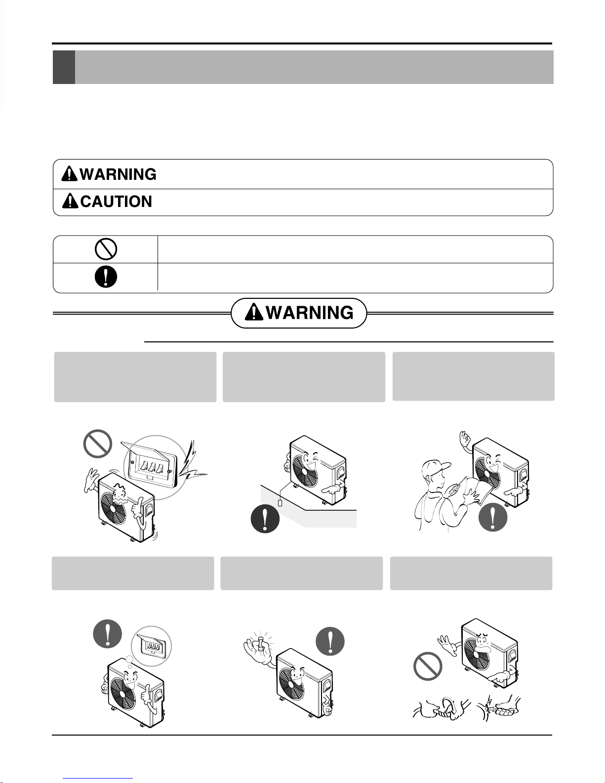
This symbol indicates the possibility of death or serious injury.
This symbol indicates the possibility of injury or damage to properties only.
■ Installation
Be sure not to do.
Be sure to follow the instruction.
Do not use a defective or underrated circuit breaker. Use this
appliance on a dedicated circuit.
• There is risk of fire or electric
shock.
Always ground the product.
• There is risk of fire or electric
shock.
Install the panel and the cover
of control box securely.
• There is risk of fire or electric
shock.
Always install a dedicated circuit and breaker.
• Improper wiring or installation may
cause fire or electric shock
Use the correctly rated breaker or fuse.
• There is risk of fire or electric
shock.
Do not modify or extend the
power cable.
• There is risk of fire or electric
shock.
Safety Precautions
4 Universal System Air Conditioner
■ Operational
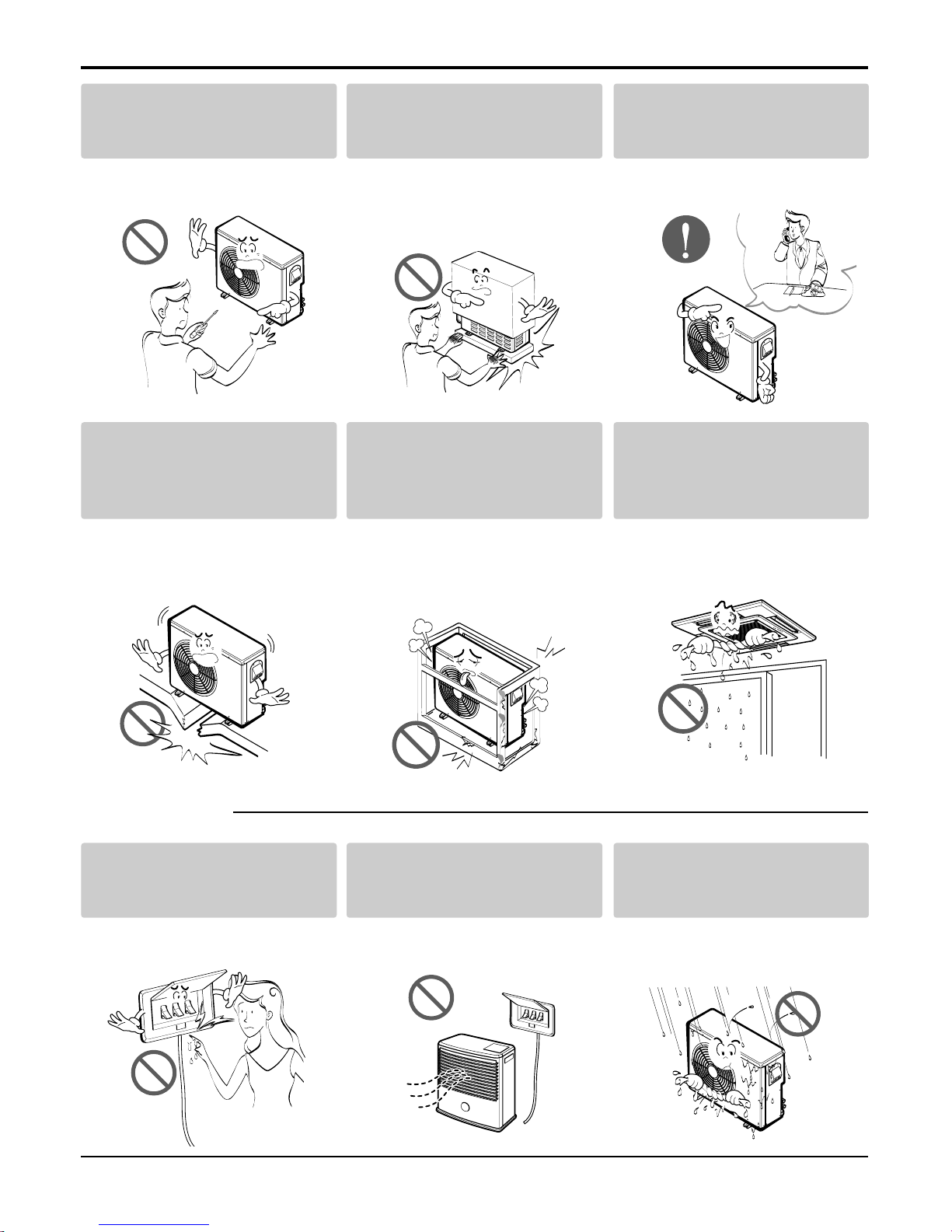
Do not install, remove, or reinstall the unit by yourself
(customer).
• There is risk of fire, electric shock,
explosion, or injury.
Be cautious when unpacking
and installing the product.
• Sharp edges could cause injury.
Be especially careful of the case
edges and the fins on the condenser and evaporator.
For installation, always contact the dealer or an
Authorized Service Center.
• There is risk of fire, electric shock,
explosion, or injury.
Do not install the product on a
defective installation stand.
• It may cause injury, accident, or
damage to the product.
Be sure the installation area
does not deteriorate with age.
• If the base collapses, the air conditioner could fall with it, causing
property damage, product failure,
and personal injury.
Do not let the air conditioner
run for a long time when the
humidity is very high and a
door or a window is left open.
• Moisture may condense and wet or
damage furniture.
Do not touch(operate) the
product with wet hands.
• There is risk of fire or electrical
shock.
Do not place a heater or other
appliances near the power
cable.
• There is risk of fire or electric
shock.
Do not let electric parts of the
product get wet.
• There is risk of fire, failure of the
product, or electric shock.
Safety Precautions
Service Manual 5
■ Installation
Do not open the inlet grill of the product during
operation. (Do not touch the electrostatic filter,
if the unit is so equipped.)
• There is risk of physical injury, electric shock, or product failure.
Be cautious that water could not enter the
product.
• There is risk of fire, electric shock, or product damage.
Always check for gas (refrigerant) leakage after
installation or repair of product.
• Low refrigerant levels may cause failure of product.
Install the drain hose to ensure that water is
drained away properly.
• A bad connection may cause water leakage.
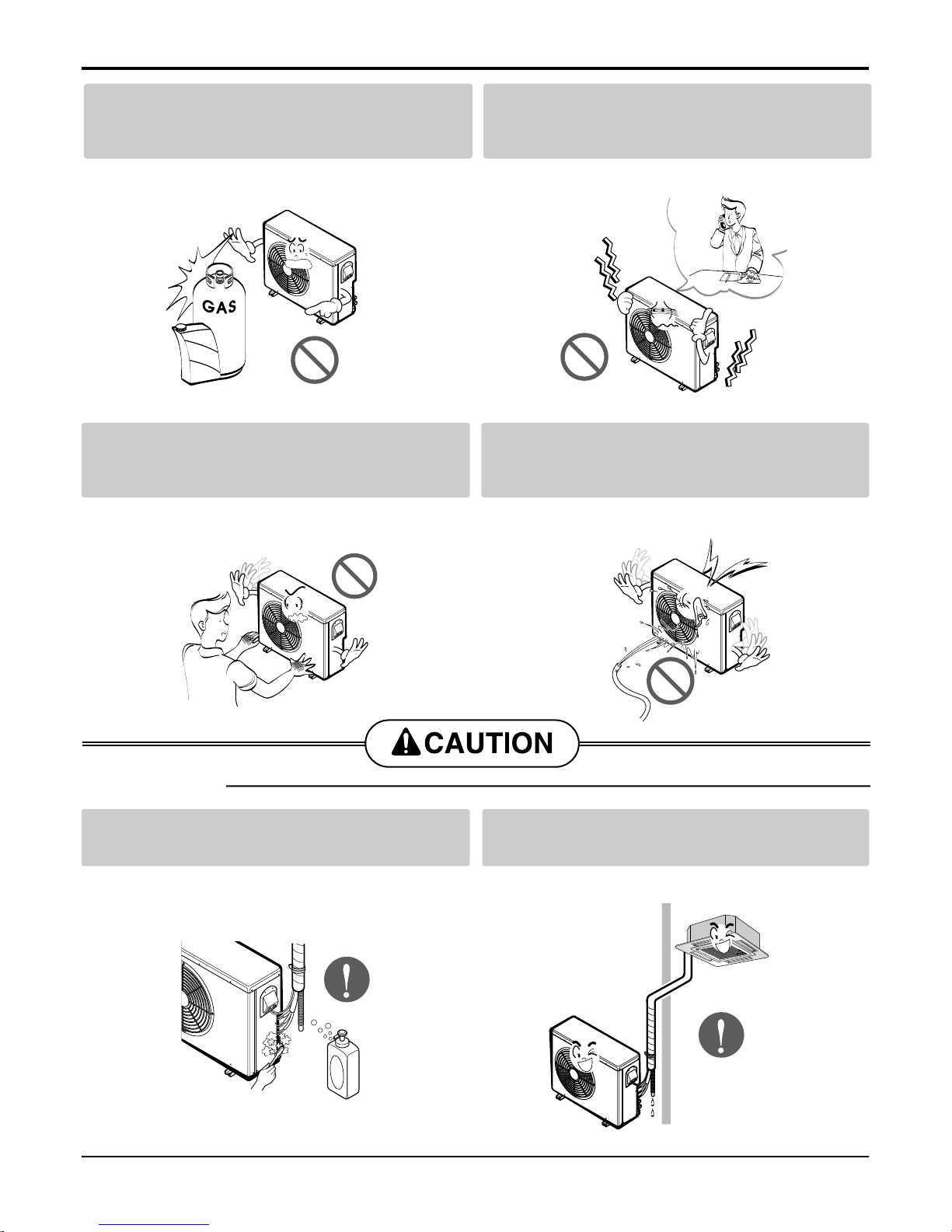
Do not store or use flammable gas or combustibles near the product.
• There is risk of fire or failure of product.
If strange sounds, or small or smoke comes
from product. Turn the breaker off or disconnect the power supply cable.
• There is risk of electric shock or fire.
Gasolin
Safety Precautions
6 Universal System Air Conditioner
Keep level even when installing the product.
• To avoid vibration or water leakage.
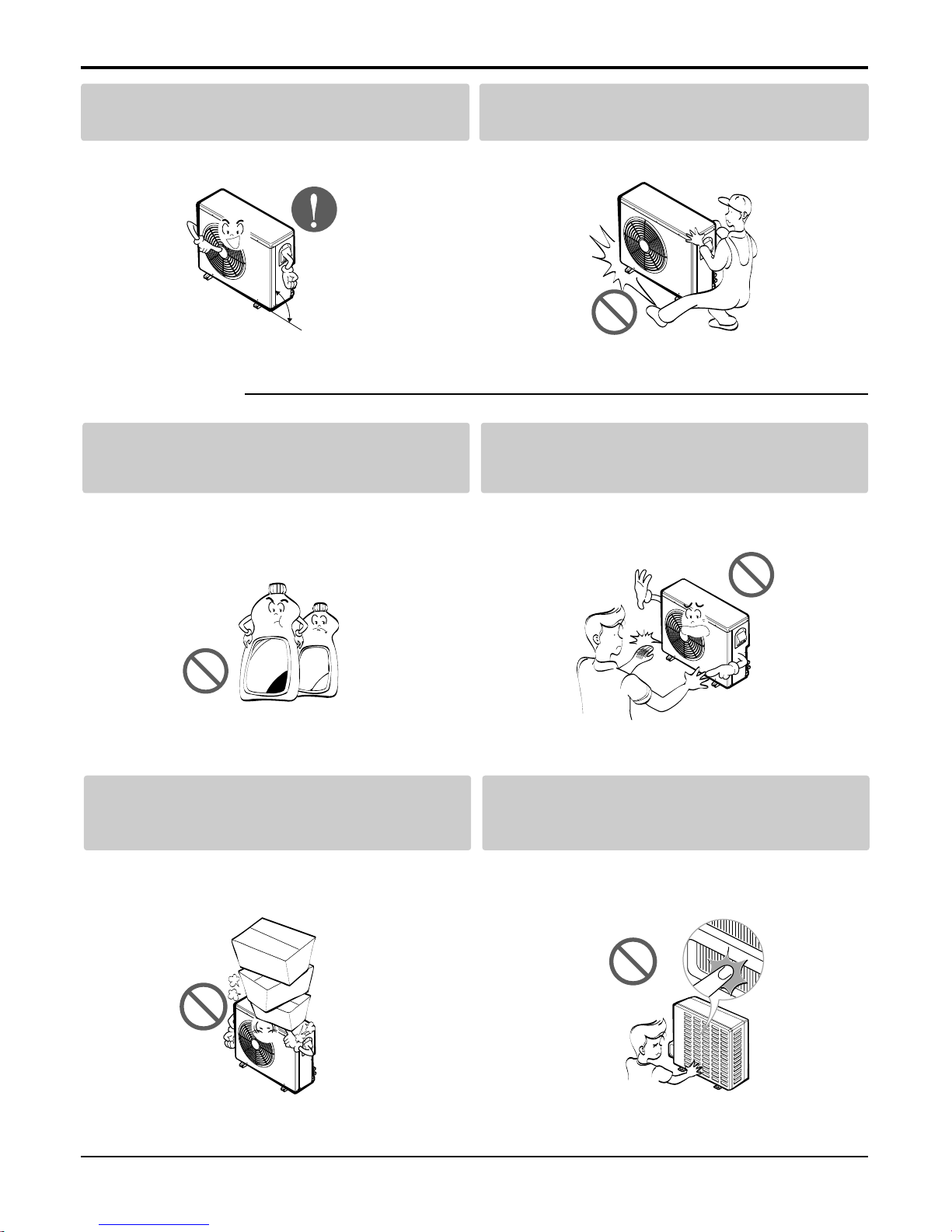
Use two or more people to lift and transport
the product.
• Avoid personal injury.
Use a soft cloth to clean. Do not use harsh
detergents, solvents, etc.
• There is risk of fire, electric shock, or damage to the
plastic parts of the product.
Do not touch the metal parts of the product
when removing the air filter. They are very
sharp!
• There is risk of personal injury.
Do not step on or put anyting on the product.
(outdoor units)
• There is risk of personal injury and failure of product.
Do not insert hands or other objects through
the air inlet or outlet while the product is operated.
• There are sharp and moving parts that could cause
personal injury.
90˚
Wax
Thinner
■ Operational

I. Indoor Units
Introduction.......................................................................................................8
Ceiling Cassette 4-way...................................................................................10
Ceiling & Floor................................................................................................31
Ceiling Concealed Duct..................................................................................45
Service Manual 7
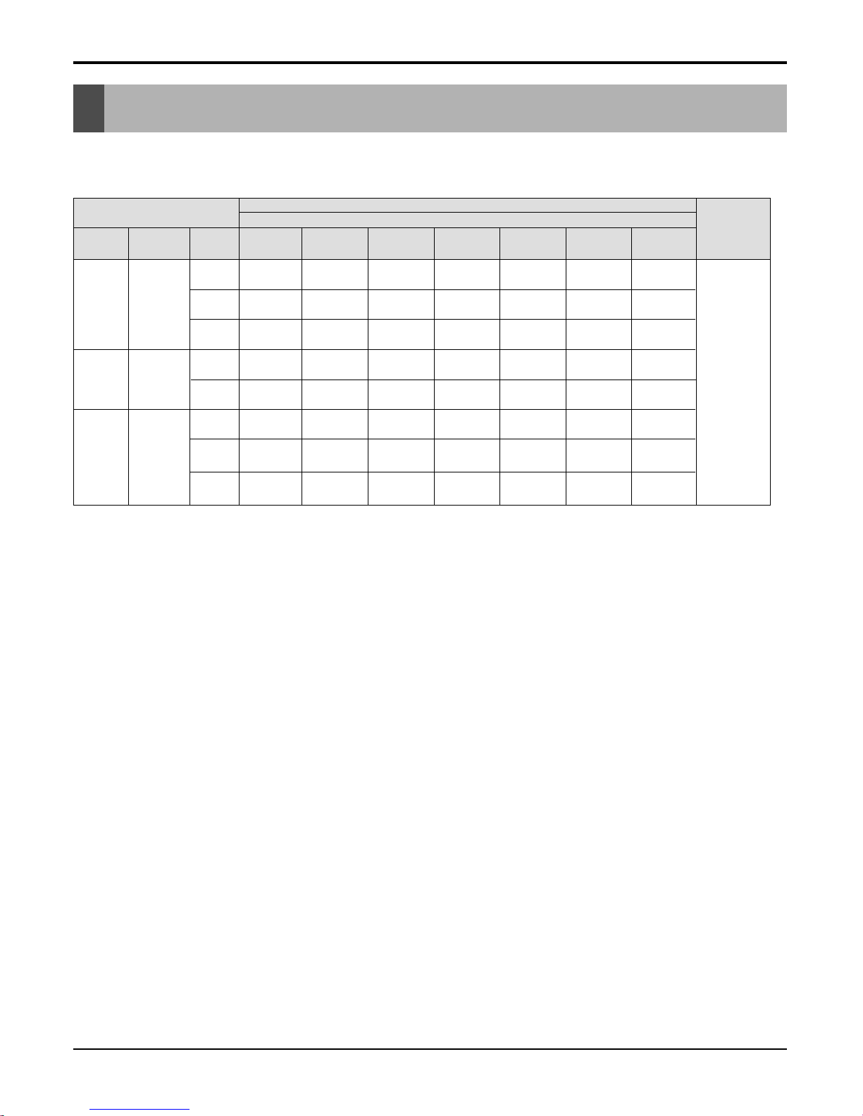
• Models List
Type Refrigerant
Chassis
name
18,000
(5.3)
24,000
(7.0)
30,000
(8.8)
36,000
(10.6)
TE
TF
TD
Ceiling
&
Floor
R410A
VB
BH
BG
12,000
(3.5)
BR
48,000
(14.1)
60,000
(17.6)
VE
1Ø, 220-240V,
50Hz
Model name
Nominal capacity [Btu/h(kW)]
Power
Supply
R410A
Ceiling
Cassette
4-Way
Ceiling
Concealed
Duct
Indoor unit
R410A
ATNH126ELFB
[UT12 NEB]
ATNH186ELFB
[UT18 NEB]
AVNH186BLAB
[UV18 NBB]
AVNH246BLAB
[UV24 NBB]
AVNH306BLAB
[UV30 NBB]
ABNH306GLAB
[UB30 NGB]
ABNH366GLAB
[UB36 NGB]
ATNH246FLFB
[UT24 NFB]
ATNH306FLFB
[UT30 NFB]
ATNH366DLFB
[UT36 NDB]
ATNH486DLFB
[UT48 NDB]
ATNH606DLFB
[UT60 NDB]
ABNH486RLAB
[UB48 NRB]
ABNH606RLAB
[UB60 NRB]
--
--
-
-
--
-- -
-- -
-
AVNH126ELAB
[UV12 NEB]
---
-
--
-
--
-
-
--
--
---
ABNH186HLAB
[UB18 NHB]
ABNH246HLAB
[UB24 NHB]
----
--
8 Universal System Air Conditioner
Introduction
Introduction
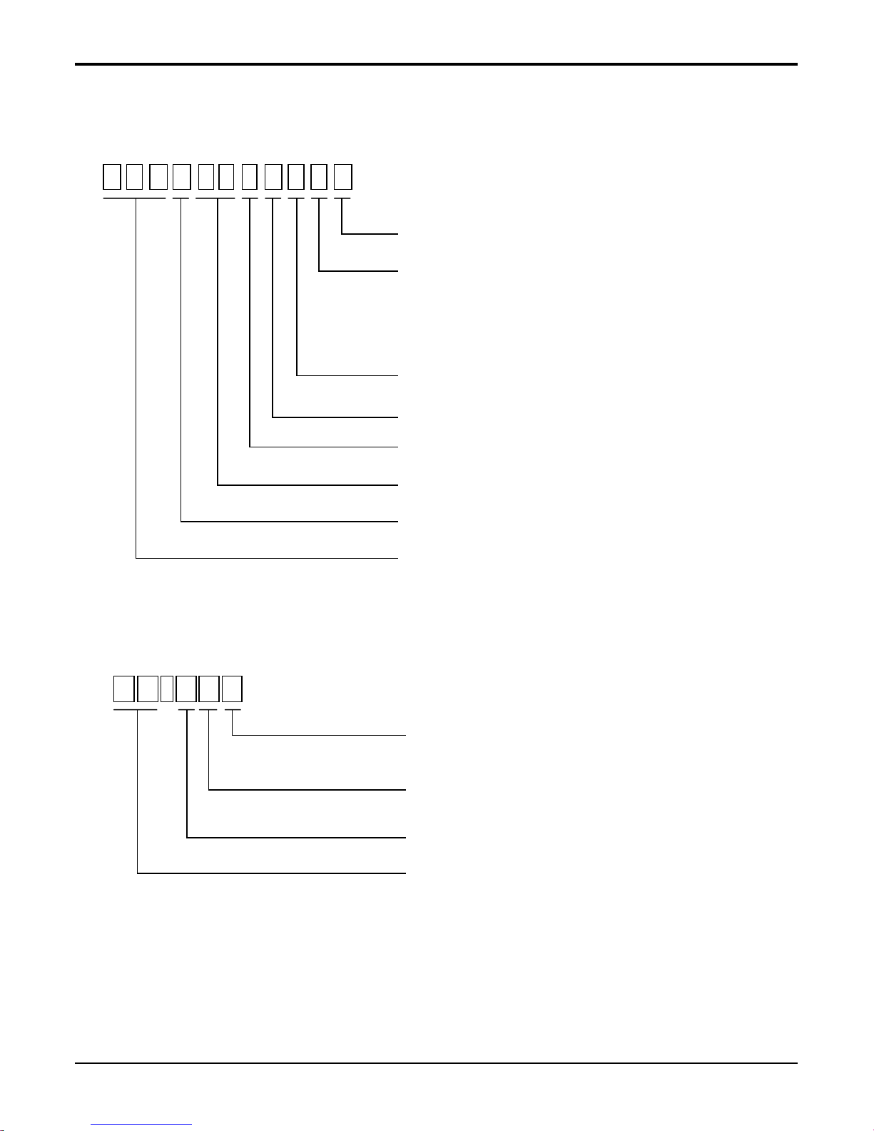
• Model Number Nomenclature
Indoor unit
Decoration panel(For Ceiling Cassette Models)
A T N H 1 8 6 E L FB
Serial Number
Functions
A : Basic B : Low Ambient
C : Plasma Filter E : Elevation Grille
F : Elevation Grille + Plasma Filter
H : Plasma Filter + Low Ambient
L : Nano Plasma M : Nano Plasma + Elevation Grille
Look
L : Basic
Chassis Name
Electrical Ratings
6:1Ø,220V~240V,50Hz 8:3Ø,380V~415V,50Hz
Nominal Cooling Capacity in Btu/h
Ex) 18 -> 18,000 Btu/h, 48 -> 48,000 Btu/h
Model Type
C : Cooling Only H : Heat Pump
Indicates that this is a indoor unit for R410A
ATN : Ceiling cassette type indoor unit
ABN : Ceiling concealed duct type indoor unit
AVN : Convertible type indoor unit
P T - H EC
Functions
A : Basic C : Plasma Air Purifier
E : Elevation Grille F : Elevation Grille + Plasma Air Purifier
Indoor Unit Chassis
D : D Chassis E : E Chassis F : F Chassis
Model Type
C : Cooling Only H : Heat Pump
Decoration Panel of Ceiling Cassette Type Indoor Unit
Service Manual 9
Introduction
10 Universal System Air Conditioner
Ceiling Cassette 4-way
Contents
1. Features & Benefits ..............................................................................11
2. List of Functions....................................................................................15
3. Specifications........................................................................................16
4. Dimensional Drawings ..........................................................................18
5. Wiring Diagrams...................................................................................21
6. Piping Diagrams....................................................................................22
7. Operating Instructions...........................................................................23
8. Installation.............................................................................................25
9. Accessories ..........................................................................................30
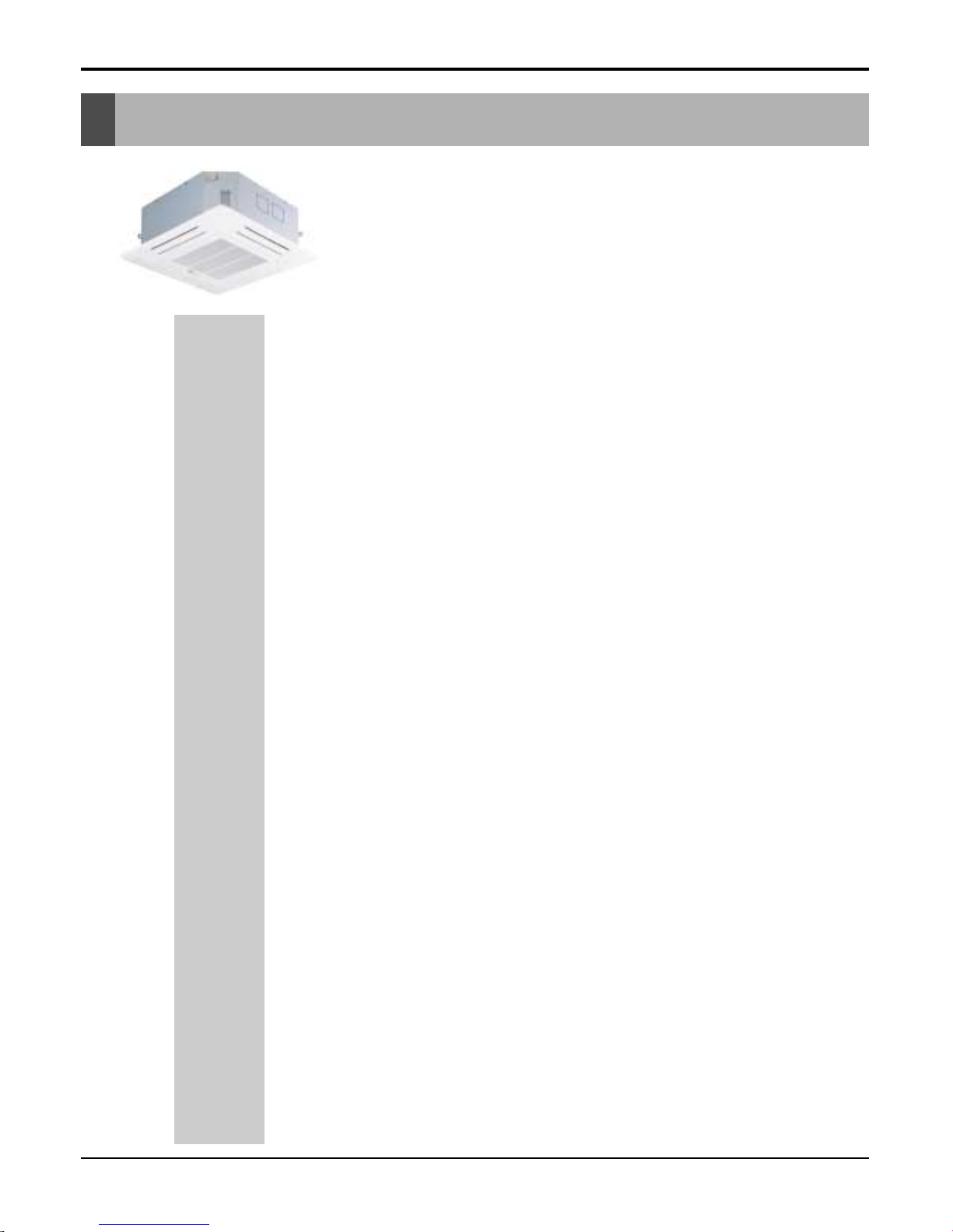
Ceiling Cassette 4-way
(R410A·Indoor Units)
ATNH-EL/FL/DL
Ceiling Cassette 4-way
(18k Btu/h model)
■ Convenience
• Auto elevation grille(Accessory)
• Tele control(Optional)
• LCD wired remote control
• Group control
• Central control(Accessory)
• Weekly progam
■ Cleanness
• Plasma air purifying system
• Hygienic and easy to clean filter
■ Easy Installation
• Compact design & easy installation
• High ceiling corresponding operation
• High head drain pump(700mm)
■ Comfort & Reliability
• Low noise with 3-dimensional turbo fan
• 2-Thermistor control(Main body & Remote control)
• Zero stanby power consumption
• Jet cool
• Swirl swing
• Space control
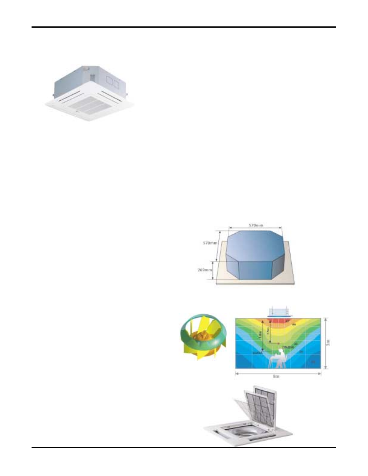
Compact Design and Easy Installation
Only about 269mm height in the ceiling is sufficient for
installation space.
A smaller size than a Textile(600X600) is very convenient for installation.
Low Noise with 3-dimensional
turbo fan
The most advanced low-noise design.
The adoption of turbo-fan and round type heat
exchanger provides the quietest operation.
Hygienic and Easy-to-Clean Filter
Washable and anti bacteria filter is adopted.
It is easy to open grille and replace clean filter.
Service Manual 11
Ceiling Cassette 4-way
1. Features & Benefits
12 Universal System Air Conditioner
Ceiling Cassette 4-way
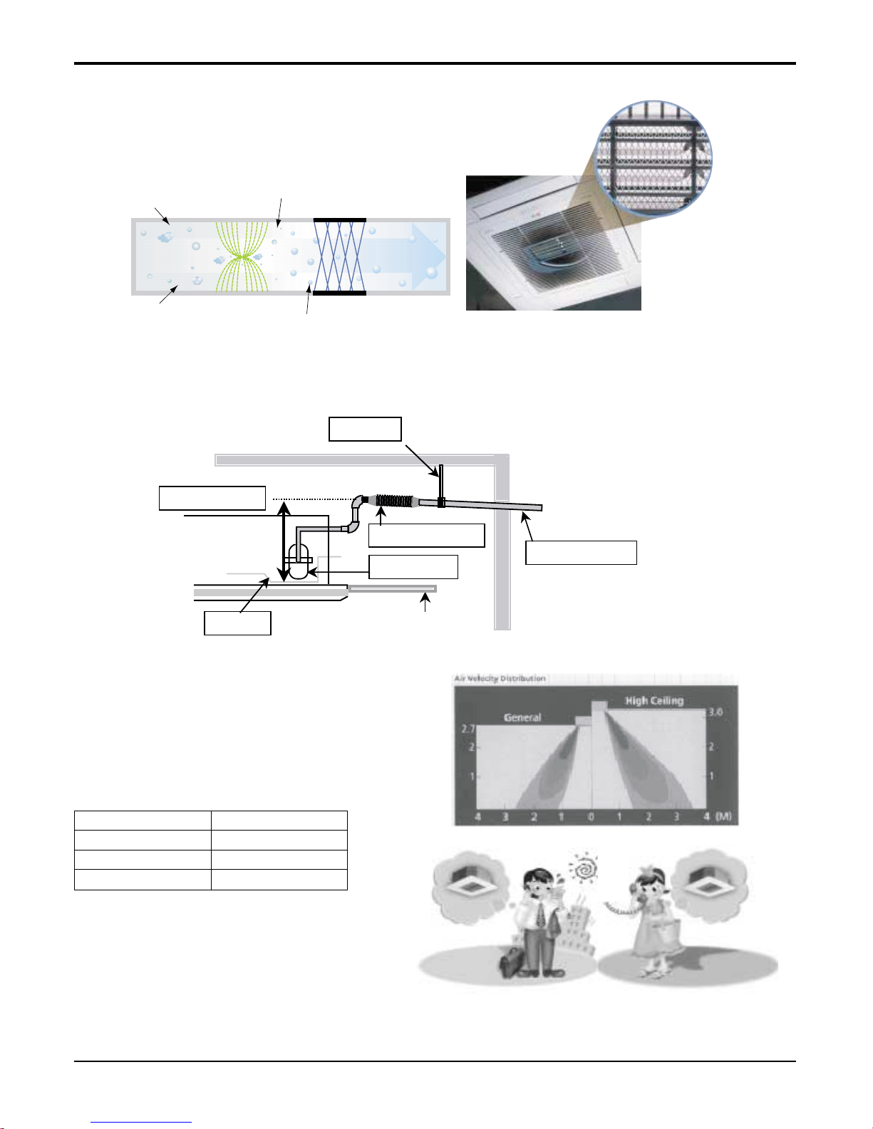
Ceiling Board
Drain Pan
Maximum 700mm
Drain Pump
Flexible drain hose
Pipe fixture
Slope 1/50~1/100
Hard Tube(ex.PVC)
+
+
+
+
Polluted Air
Purified fresh Air
+4.8KV discharge
Ionizer Photo-Catalyst Coated Mesh
Dust particles
Odour
Dust electrode discharge
Odour molecule
Generating plasma
Plasma Air Purifying System
The PLASMA Air Purifying Function not only removes microscopic contaminants and dust, but also removes house
mites, pollen, and pet fur helps to prevent allergic diseases
like asthma.
High Head Drain Pump(700mm)
Built-in Drain Pump drains out water automatically.
A standard drain-head height of up to 700 mm is possible, creating the ideal solution for perfect water drainage.
High-Ceiling Corresponding Operation
According to the height of the installation, it provides variability of indoor fan motor rpm. If the height of installation is
low then you can adjust low rpm of indoor fan motor. On
the other hand if the height of the installation is high you
can adjust high rpm of indoor fan motor. Selection of
speed can be done by slide switch at the back of the LCD
wired remote.
Tele Control (Accessory)
- It provides you ease of control. Air conditioner
can be switched on/off by the telephone. It
saves time & energy.
ON
ONON OFF
OFF
OFFOFF
In Advance by Telephone
Before Coming Home...
In case of Going out
Without Turning off the
Air Conditioner...
Over than 3.3mHigh Ceiling
2.7~3.3mStandard
Ceiling HeightSwitch selection
Less than 2.7mLow Ceiling
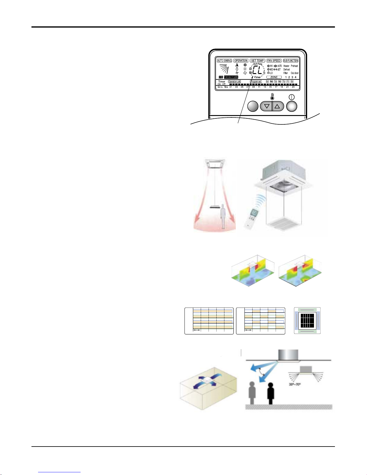
Child Lock Function
-It prevents the children or others from tampering
with the control buttons. Unit can be controlled by
the wireless remote controller. This can be easily set
by pressing timer key & Min key simultaneously.
After child lock is set, pressing any key will display
CL on the LCD for 3 seconds and all the keys will be
ineffective.
Auto Elevation Grille(Accessory)
-Auto Elevation Grille is automatically down to height
of max. 3.1 m. So it enables to install the Indoor unit
at high ceiling space. And Auto Elevation Grille
makes you cleaning the filter easily.
CHILD LOCK
-Display
71
Vane 2
Swirl Swing(New)4- Open(Conventional)
Swirl Swing(New)4- Open(Conventional)
2.4% 4.8%100% Improved
Comparison of Air Flow Types
Comparison of Floor
Temp. Distribution(20°C)
Vane 1 Close OpenOpen
Open
Open
Open
Close CloseOpen
Vane 3 Close Open Close CloseOpen
OpenOpen Close CloseOpen
Vane 2
OpenOpen
Time
Close CloseOpen
Vane 4
Vane 1
Vane 3
Vane 2
Time
Vane 4
Vane 3
Vane 4
Vane 1
Swirl Swing
- It is the function for comfort cooling/heating operation.
- The diagonal two louvers are opened the
more larger than the other louvers.
After one minute, it is opposite.
Space Control
Vanes angle can be controlled by pair, considering its
installation environment.
- For example direct drafts can be annoying, leading
to discomfort and reduced productivity vane control
helps to eliminate this problem.
- Easily controlled by wired remote control.
- Air Flow can be controlled easily regarding any
space environment.
Service Manual 13
Ceiling Cassette 4-way
14 Universal System Air Conditioner
Ceiling Cassette 4-way
Weekly Program
- On/Off schedule of operation for a period of ONE
week.
No need to turn the unit On/OFF manually during
working days. On/Off time is scheduled in micom of
the wired remote control.
Auto Restart Operation
- Whenever there is electricity failure to the unit, and after resumption of the power, unit will start in the same
mode prior to the power failure. Memorized condition are on / off condition, operating mode (cooling/heating),
set temperature and fan speed.The unit will memorize the above conditions and start with same memorized
condition.
Two Thermistor Control
- There may be a significant difference between the temperature taken at the installed product and indoor temperature. Two thermistor control provides option to control temperature by referring any of the two temperatures. With the help of the slide switch at the back of the LCD wired remote controller, selection of the desired
thermistor for controlling the unit can be done. One thermistor is in the Indoor unit & the other one is in the
LCD wired remote.
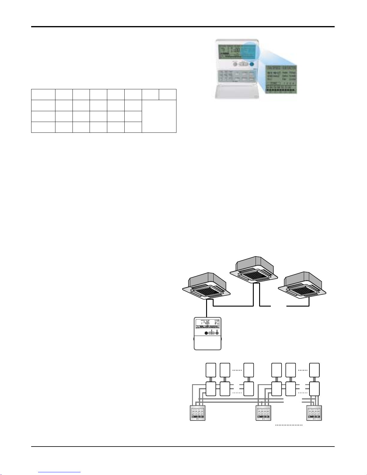
Group Control
- It enables to control as much as 16 units with the
help of one wired remote controller. All the units will
follow same setting of temperature & other sub functions.
Central Control(Accessory)
- It enables to control 16 x 8 = 128 units with the help
of 8 controllers. All units can be put on and off from
one Central Room.For Setting Temperature, Fan
Speed and other sub functions, access the respective LCD wired remote controller of each unit.
❈ Sub PI485(with wire assembly) should be pur-
chased as optional.
Operation Time Table (Example)
Mon Tue Wed Thu Fri Sat Sun
OFF
Setting
Temp.
On
Off
25°C25°C25°C25°C25°C
09:00
12:00
08:00
17:00
09:00
12:00
08:00
12:00
09:00
12:00
10mm 10mm
1216........
........
Main
PCB
Controller
# 1
Controller
# 2
Controller
# 8
M
1
Sub
1
M
2
Sub
2
M
16
Sub
16
M
17
Sub
17
M
18
Sub
18
M
128
Sub
128
Service Manual 15
Ceiling Cassette 4-way
2. List of Functions
Air supply outlet
Airflow direction control (left & right)
Airflow direction control (up & down)
Auto swing (left & right)
Air flow
Auto swing (up & down)
Airflow steps(Fan / Cool / Heat)
CHAOS swing
CHAOS wind (Auto wind)
Jet cool (Power wind)
Swirl wind
Deodorizing filter
Air purifying Plasma air purifier
Prefilter(Washable / Anti-fungus)
Drain pump
Installation
E.S.P. control
Electric heater (Operation)
High ceiling operation
Hot start
Reliability Self diagnosis
Soft dry operation
Auto changeover
Auto cleaning
Auto operation(Artificial intelligence)
Auto restart operation
Child lock
Convenience Forced operation
Group control
Sleep mode
Timer (On/Off)
Timer (weekly)
Two thermistor control
Standard wired remote controller
Deluxe wired remote controller
Individual control Simple wired remote controller
Wired remote controller(for hotel use)
Wireless remote controller(simple)
Wireless LCD remote controller
General central control(Non LGAP)
Dry contact
CAC network function
Simple central control(LGAP)
PDI(Power Distribution Indicator)
PI485
Special function kit
CTIE
Zone control
Others Thermistor
444
---
Auto Auto Auto
XXX
OOO
3/4/3 3/4/3 3/4/3
XXX
--OOO
OOO
--OOO
OOO
OOO
---
--OOO
OOO
OOO
OOO
XOX
XXX
OXO
OOO
OOO
OOO
OOO
XXX
OOO
OOO
OOO
OOO
XXX
XXX
XXX
XXX
OOO
XXX
PQDSB PQDSB PQDSB
OOO
PQNUD1S00 PQNUD1S00 PQNUD1S00
PMNFP14A0 PMNFP14A0 PMNFP14A0
XXX
XXX
AQTTA AQTTA AQTTA
FunctionCategory
ATNH-EL ATNH-FL ATNH-DL
Note: Group control & CAC network function is not available which is connected with synchro.
Sleep mode is available only in case of using wireless remote controller.
• O: Applied, • X: Not applied, • - : No relation,
• Option: Model name & price are different according to options, and assembled in factory with main unit.
• Accessory: Installed at field, ordered and purchased separately by the corresponding model name, supplied with separate package.
16 Universal System Air Conditioner
Ceiling Cassette 4-way
Note :
1. Capacities are based on the following conditions:
Cooling: - Indoor Temperature 27°C(80.6°F) DB /19°C(66.2°F) WB
- Outdoor Temperature 35°C(95°F) DB /24°C(75.2°F) WB
Heating: - Indoor Temperature 20°C(68°F) DB / 15°C(59°F) WB
- Outdoor Temperature 7°C(44.6°F) DB / 6°C(42.8°F) WB
Piping Length - Interconnecting Piping Length 7.5m
- Level Difference of Zero.
2. Cooling/heating capacity of indoor unit can be lower when it is connected to MPS variable outdoor.
3. Wiring cable size must comply with the applicable local and national code.
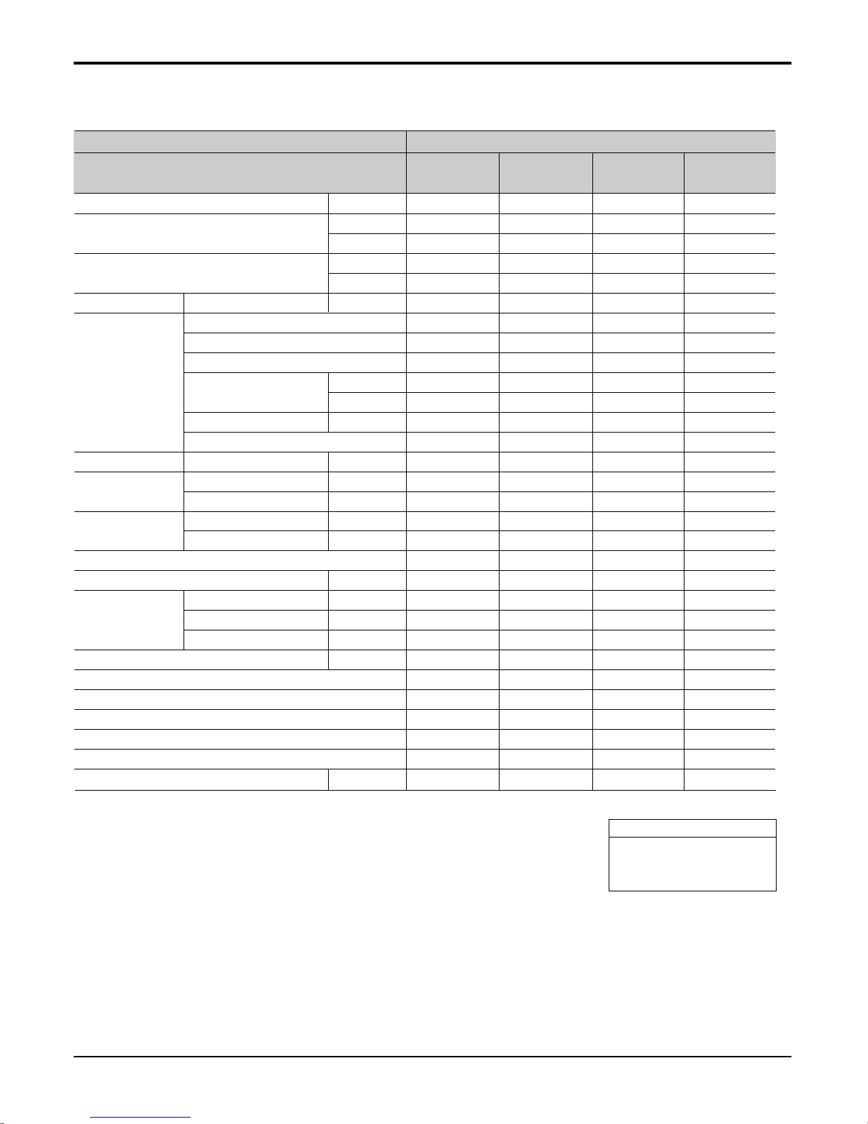
3. Specifications
Power Supply Ø/V/Hz
Cooling Capacity kW
Btu/h
Heating Capacity kW
Btu/h
Current Nominal running current A
Fan Motor Type
Fan Type
Motor Output x Number of Unit
Air Flow Rate cmm
(H/M/L) cfm
Capacitor µF/Vac
Drive
Coil Row x Column x FPI mm
Dimensions Body mm(inch)
(WxHxD) Decorative Panel mm
Weight Body kg(lbs)
Decorative Panel kg(lbs)
Air Filter
Sound Level (H/M/L) dB(A)+3
Piping Liquid mm(inch)
Connections Gas mm(inch)
Drain(OD/ID) mm
Dehumidification Rate l/h
Safety devices
Temperature Sensor
Referigerant
Referigerant Control
Connectable outdoor unit
Power and transmission interunit cable No.x mm
2
Model
ATNH126ELFB
[UT12 NEB]
ATNH186ELFB
[UT18 NEB]
ATNH246FLFB
[UT24 NFB]
ATNH306FLFB
[UT30 NEB]
Indoor unit type Ceilling Cassette - 4way
1 / 220 ~240 / 50 1 / 220 ~240 / 50 1 / 220 ~240 / 50 1 / 220 ~240 / 50
3.52 5.28 7.03 8.21
12,000 18,000 24,000 28,000
4.04 5.95 8.09 9.44
13,800 20,300 27,600 32,200
0.35 0.43 0.53 0.67
Induction Induction Induction Induction
Turbo Fan Turbo Fan Turbo Fan Turbo Fan
18.4*1 22.4*1 40.3*1 48.6*1
9.5 / 8 / 7 13 / 12 / 11 15 / 14 / 13 19 / 17 / 15
336 / 283 / 247 459 / 422 / 388 530 / 494 / 459 671 / 600 / 530
2.5/440 2.5/440 4/440 4/440
Direct Drive Direct Drive Direct Drive Direct Drive
2R x 11C x 19 2R x 11C x 19 2R x 11C x 19 2R x 12C x 21
570*269*570(22.4*10.5*22.4) 570*269*570(22.4*10.5*22.4) 744*292*744(29.3*11.5*29.3) 744*292*744(29.3*11.5*29.4)
670*30*670(26.4*1.2 *26.4) 670*30*670(26.4*1.2 *26.4) 850*30*850(33.5*1.2 *33.5) 850*30*850(33.5*1.2 *33.5)
19(41.9) 19(41.9) 24(52.9) 24(52.9)
3(6.6) 3(6.6) 3(6.6) 3(6.6)
Long life filter Long life filter Long life filter Long life filter
38 / 35 / 32 41 / 39 / 37 43 / 41 / 39 45 / 42 / 39
6.35 (1/4) 6.35 (1/4) 6.35 (1/4) 6.35 (1/4)
9.52 (3/8) 12.7 (1/2) 12.7(1/2) 15.88 (5/8)
32 / 25 32 / 25 32 / 25 32 / 25
1.2 2.4 3 3.3
Fuse, Thermal protector for fan motor Fuse, Thermal protector for fan motor Fuse, Thermal protector for fan motor Fuse, Thermal protector for fan motor
Thermistor Thermistor Thermistor Thermistor
R-410A R-410A R-410A R-410A
Capillary LEV LEV LEV
Single A Single A Single A Single A
4*0.75 4*0.75 4*0.75 4*0.75
Conversion Formula
kW = Btu/h × 0.0002931
kcal/h = Btu/h × 0.252
CFM = CMM × 35.3
Service Manual 17
Ceiling Cassette 4-way
Conversion Formula
kW = Btu/h × 0.0002931
kcal/h = Btu/h × 0.252
CFM = CMM × 35.3
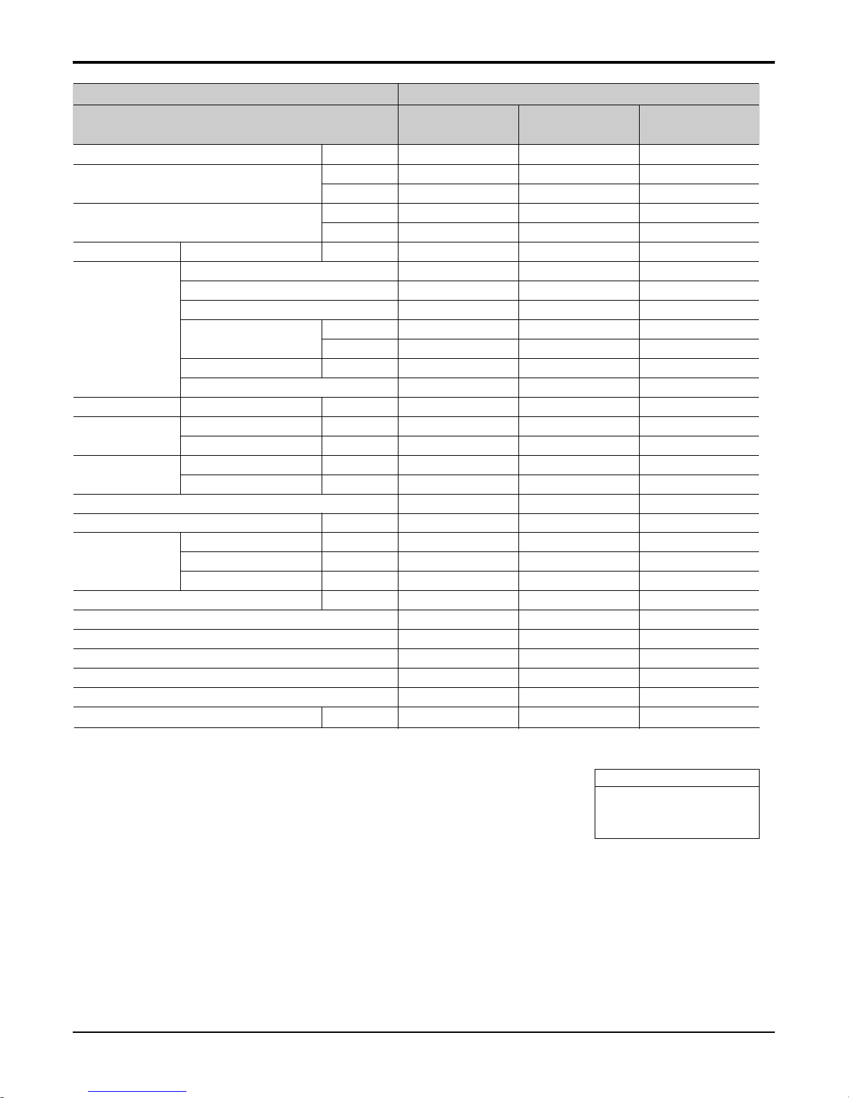
Power Supply Ø/V/Hz
Cooling Capacity kW
Btu/h
Heating Capacity kW
Btu/h
Current Nominal running current A
Fan Motor Type
Fan Type
Motor Output x Number of Unit
Air Flow Rate cmm
(H/M/L) cfm
Capacitor µF/Vac
Drive
Coil Row x Column x FPI mm
Dimensions Body mm(inch)
(WxHxD) Decorative Panel mm
Weight Body kg(lbs)
Decorative Panel kg(lbs)
Air Filter
Sound Level (H/M/L) dB(A)+3
Piping Liquid mm(inch)
Connections Gas mm(inch)
Drain(OD/ID) mm
Dehumidification Rate l/h
Safety devices
Temperature Sensor
Referigerant
Referigerant Control
Connectable outdoor unit
Power and transmission interunit cable No.x mm
2
Model
ATNH366DLFC
[UT36 NDC]
ATNH486DLFB
[UT48 NDB]
ATNH606DLFB
[UT60 NDB]
Indoor unit type Ceilling Cassette - 4way
1 / 220 ~240 / 50 1 / 220 ~240 / 50 1 / 220 ~240 / 50
10.6 14.1 16.4
36,000 48,000 56,000
12.1 15.5 18.1
41,400 52,800 61,600
0.76 1.5 1.8
Induction Induction Induction
Turbo Fan Turbo Fan Turbo Fan
52.5*1 58.5*1 107*1
25 / 23 / 21 32 / 30 / 28 34 / 32 / 30
883 / 812 / 742 1059 /988 / 918 1200 / 1130 / 1059
2.5/440 6/400 6/400
Direct Drive Direct Drive Direct Drive
2R x 12C x 21 2R x 12C x 21 2R x 12C x 21
840*288*840(33.1*11.3*33.1) 840*288*840(33.1*11.3*33.1) 840*288*840(33.1*11.3*33.1)
950*30*950(37.4*1.2 *37.4) 950*30*950(37.4*1.2 *37.4) 950*30*950(37.4*1.2 *37.4)
32(70.4) 32(70.4) 32(70.4)
5(11) 5(11) 5(11)
Long life filter Long life filter Long life filter
40 / 38 / 36 43 / 41 / 39 50 / 47 / 43
6.35 (1/4) 9.52 (3/8) 9.52 (3/8)
15.88(5/8) 19.05(3/4) 19.05(3/4)
32 / 25 32 / 25 32 / 25
4.0 5.5 6.5
Fuse, Thermal protector for fan motor Fuse, Thermal protector for fan motor Fuse, Thermal protector for fan motor
Thermistor Thermistor Thermistor
R-410A R-410A R-410A
LEV LEV LEV
Single A Single A Single A
4*0.75 4*0.75 4*0.75
Note :
1. Capacities are based on the following conditions:
Cooling: - Indoor Temperature 27°C(80.6°F) DB /19°C(66.2°F) WB
- Outdoor Temperature 35°C(95°F) DB /24°C(75.2°F) WB
Heating: - Indoor Temperature 20°C(68°F) DB / 15°C(59°F) WB
- Outdoor Temperature 7°C(44.6°F) DB / 6°C(42.8°F) WB
Piping Length - Interconnecting Piping Length 7.5m
- Level Difference of Zero.
2. Cooling/heating capacity of indoor unit can be lower when it is connected to MPS variable outdoor.
3. Wiring cable size must comply with the applicable local and national code.
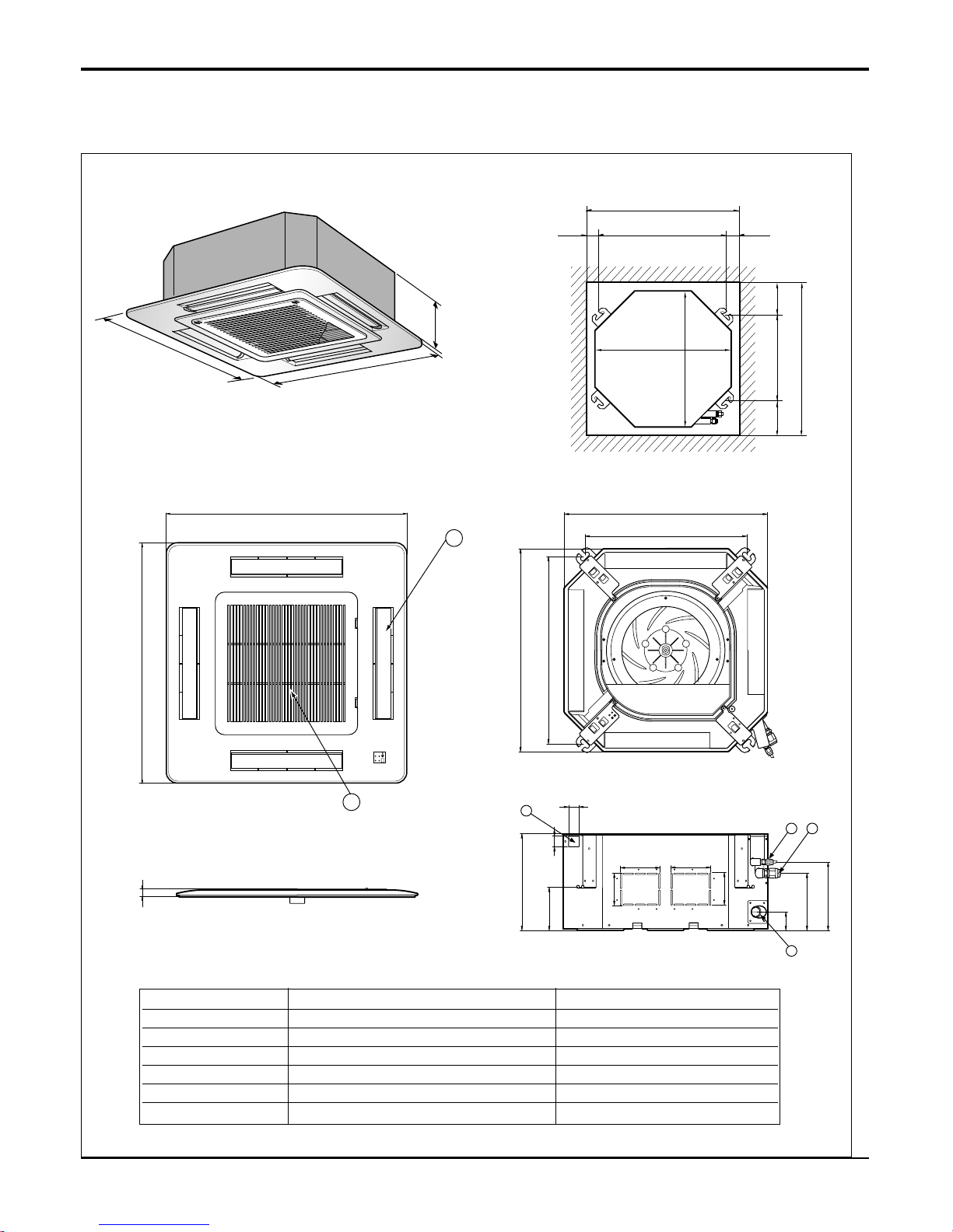
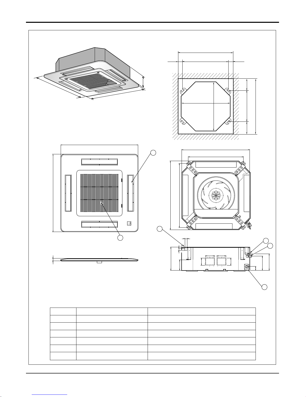
18 Universal System Air Conditioner
Ceiling Cassette 4-way
269
570
269
190.5
160
52
90
90
120.4
30
521
570
450
40
110 110
670
670
4
132
Unit:mm
570 Unit size
570 Unit size
450 (Hanging bolt)
7575
600 (Ceiling opening)
600 (Ceiling opening)
521(Hanging bolt)
39.5
39.5
670
670
5
6
30
ATNH-EL(Decoration Panel : PT-HEA, PT-HEC)
(unit : mm)
Number Name Descripition
1 Liquid pipe connection ø6.35 flare
2 Gas pipe connection 12k: ø9.52, 18k:
ø12.7 flare
3 Drain pipe connection
4 Power supply connection
5 Air discharge grille
6 Air suction grille
4. Dimensional Drawings
Service Manual 19
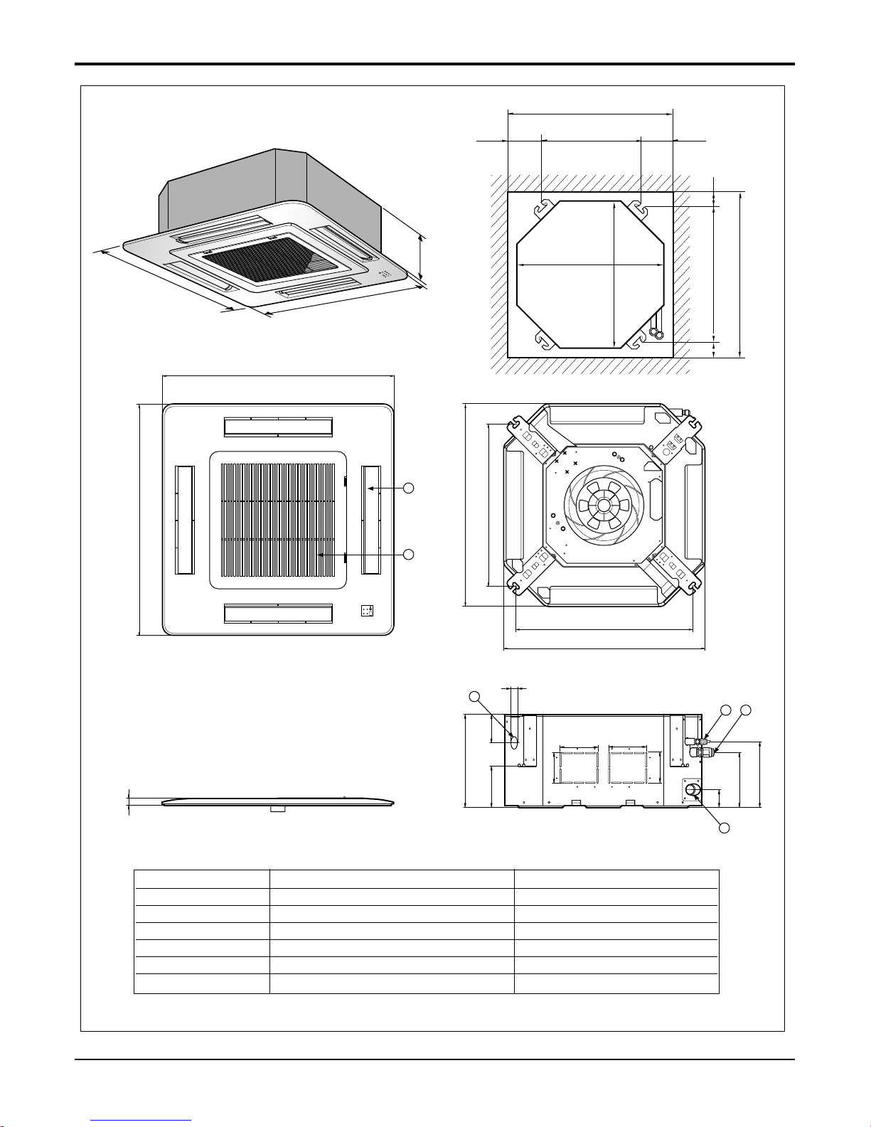
Ceiling Cassette 4-way
292
850
850
850
850
744
658
572
744
292
212
150
54
90
90
192 117
70
110 110
4
132
5
6
Unit:mm
744 Unit size
744 Unit size
658 (Hanging bolt)
6666
790 (Ceiling opening)
790 (Ceiling opening)
572(Hanging bolt)
109
109
30
ATNH-FL(Decoration Panel : PT-HFA, PT-HFC)
(unit : mm)
Number Name Descripition
1 Liquid pipe connection ø6.35 flare
2 Gas pipe connection 24K:
ø12.7, 30K: ø15.88 flare
3 Drain pipe connection
4 Power supply connection
5 Air discharge grille
6 Air suction grille
20 Universal System Air Conditioner
Ceiling Cassette 4-way
ATNH-DL(Decoration Panel : PT-HDA, PT-HDC)
288
950
950
290
210.5
180
52
140
40
110
30
90
90
110
840
785
840
678
840 Unit size
840 Unit size
672 (Hanging bolt)
101.5101.5
875 (Ceiling opening)
875 (Ceiling opening)
785(Hanging bolt)
45
45
Unit:mm
4
1
2
3
950
950
5
6
30
Number Name Descripition
1 Liquid pipe connection 36k:ø6.35, 48/60k: ø9.52 flare
2 Gas pipe connection 36k:ø15.88, 48/60k: ø19.05flare
3 Drain pipe connection
4 Power supply connection
5 Air discharge grille
6 Air suction grille
(unit : mm)
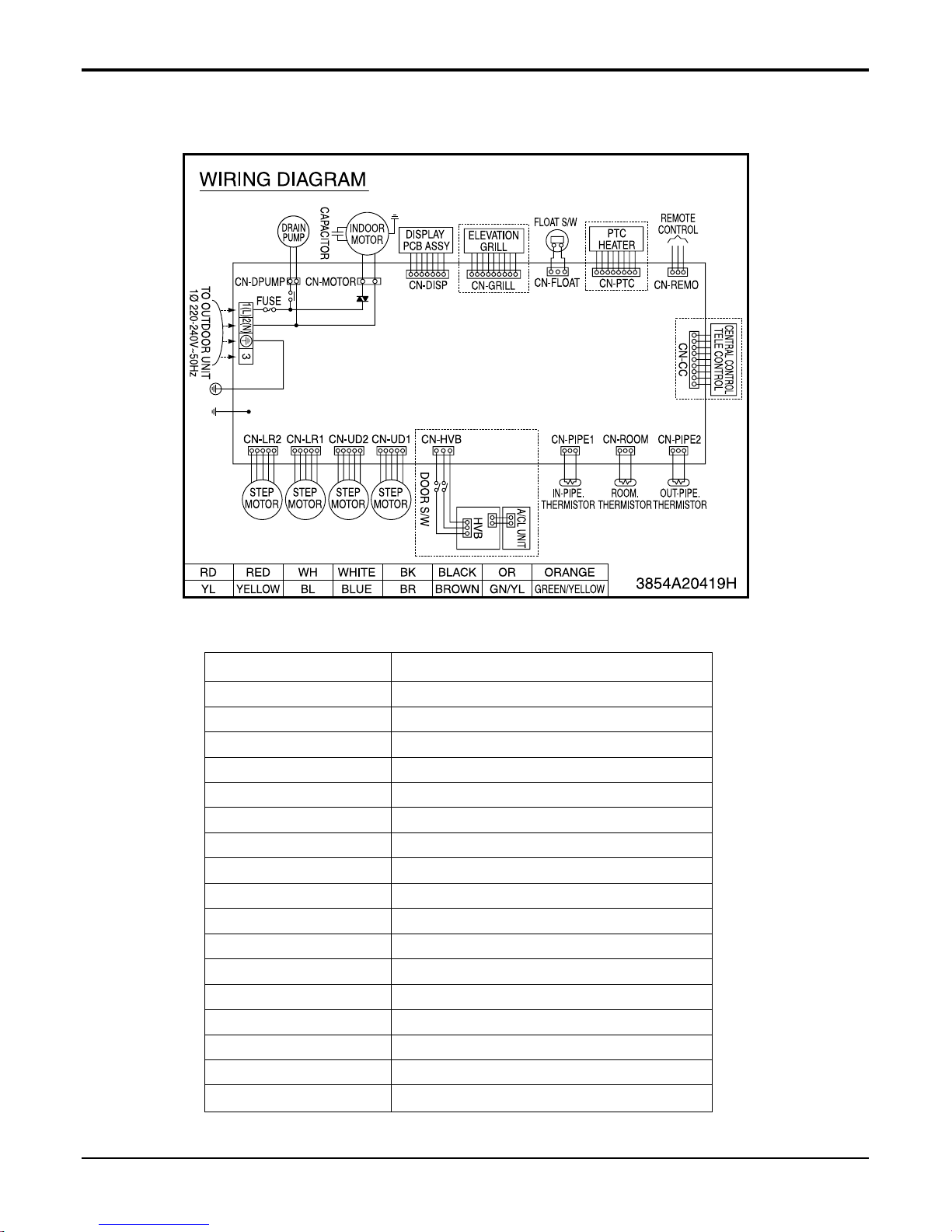
Service Manual 21
Ceiling Cassette 4-way
CONNECTOR NUMBER LOCATION
CN-POWER AC POWER SUPPLY
CN-MOTOR BLDC FAN MOTOR OUTPUT
CN-D/PUMP DRAIN PUMP OUTPUT
CN-DISP DISPLAY
CN-FLOAT FLOAT SWITCH INPUT
CN-PTC PTC HEATER INUT
CN-REMO REMOTE CONTROL
CN-GRILL GRILL CONTROL
CN-CC CENTRAL CONTROL
CN-PIPE2 DISCHARGE PIPE SENSOR
CN-ROOM ROOM SENSOR
CN-PIPE1 PIPE SENSOR
CN-HVB AIR CLEANER
CN-UD1 STEP MOTOR
CN-UD2 STEP MOTOR
CN-LR1 STEP MOTOR
CN-LR2 STEP MOTOR
5. Wiring Diagrams
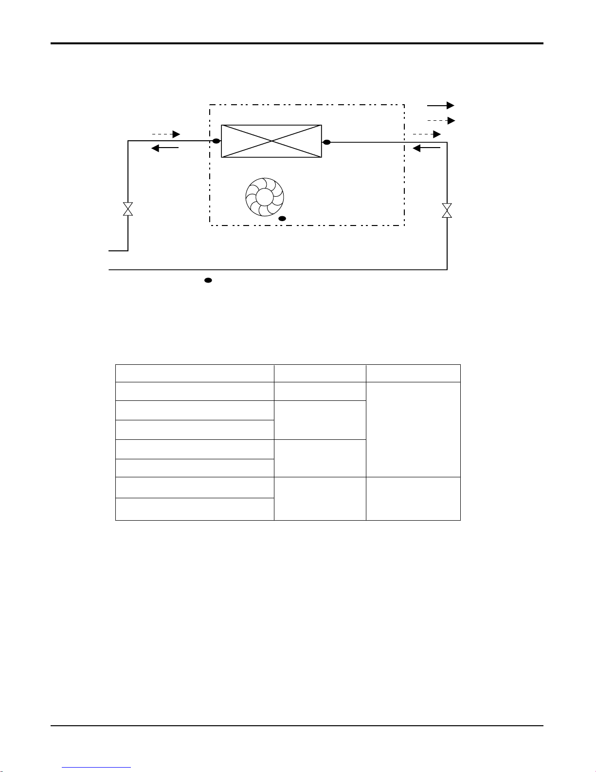
22 Universal System Air Conditioner
Ceiling Cassette 4-way
Refrigerant pipe connection port diameter
Model
ATNH126ELFB [UT12 NEB]
ATNH186ELFB [UT18 NEB]
ATNH246FLFB [UT24 NFB]
ATNH306FLFB [UT30 NFB]
ATNH366DLFB [UT36 NDB]
ATNH486DLFB [UT48 NDB]
ATNH606DLFB [UT60 NDB]
Gas
9.52(3/8)
12.7(1/2)
15.88(5/8)
19.05(3/4)
Liquid
6.35(1/4)
9.52(3/8)
[unit: mm(inch)]
Heat Exchanger
Turbo Fan
lndoor unit
:Heating
:Cooling
: Thermistor
6. Piping Diagrams
Service Manual 23
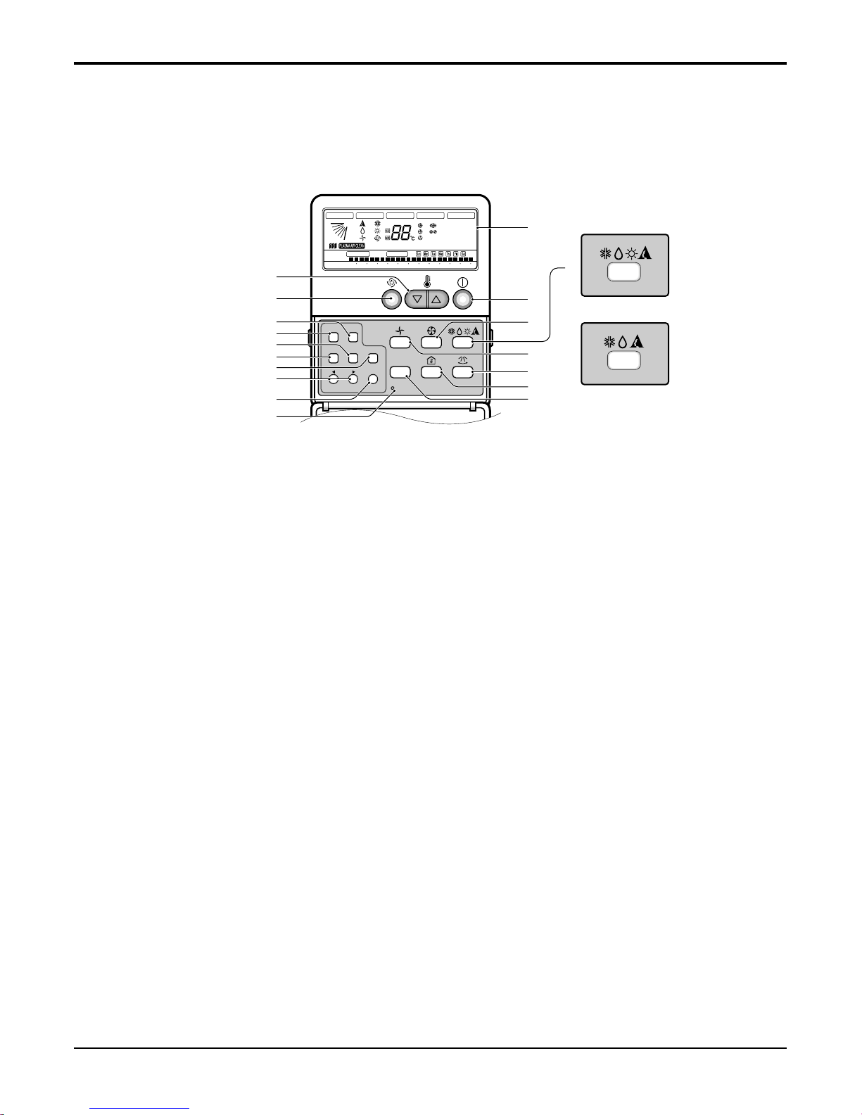
Ceiling Cassette 4-way
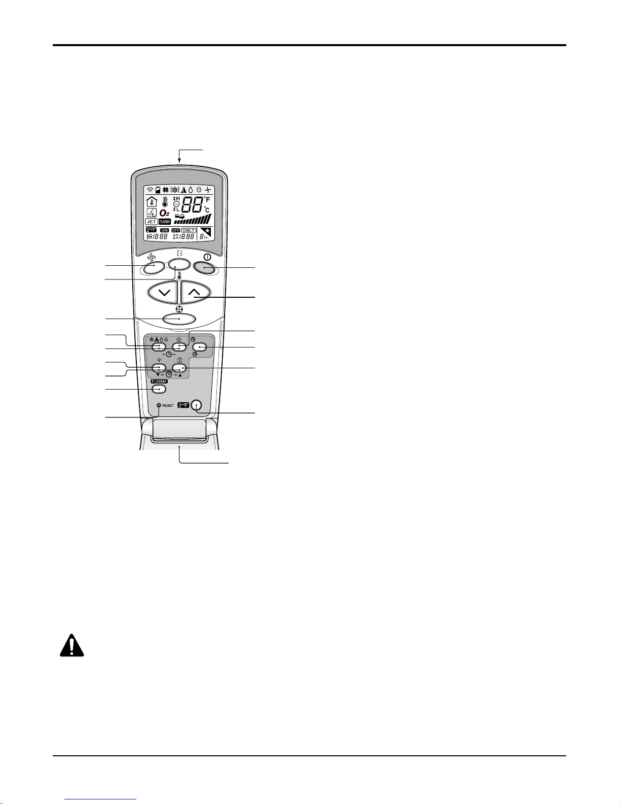
7. Operating Instructions
1. Operation display
Displays the operation conditions.
2. On/Off Button
Operation starts when this button is pressed, and
stops when the button is pressed again.
3. Set Temperature Button
Used to set the temperature when the desired temperature is obtained.
4. FAN Operation Button
Used to circulate room air without cooling or heating.
5. Fan Speed (Jet Cool Button: 4 way)
Used to set the desired fan speed or select Jet cool
mode.
6. Operation Mode Selection Button
Used to select the operation mode.
• Auto Operation Mode
• Cooling Operation Mode
• Soft Dry Operation Mode
• Heating Operation Mode(except cooling model)
7. Auto Swing Button
Used to swing up and down.
8.
Room Temperature Checking Button
Used to check the room temperature.
9. Plasma Air Clean Button (optional)
10. Timer Cancel Button
Used to cancel the timer.
11. Timer Set Button
Used to set the timer when the desired time is
obtained.
12.
Week Button
Used to set a day of the week.
13. Program Button
Used to set the weekly timer.
14. Holiday Button
Used to set a holiday of the week.
15. Time Set Button
Used to set the time of the day and change the time
in the weekly timer Function.
16. Set and Clear Button
Used to set and clear the weekly timer.
17. Swirl Button (4 way)
Used to select swirl mode.
Jet Cool Button (1 way)
18. Reset Button
Used to set the current time and clear the setting
time.
❈
Display temperature can be different from actual room temperature if the remote controller is installed
at the place where sun-rays are falling directly or the place nearby heat source.
Timer Cancel
Program Week
Hour Min
Holiday
Set/Clr
RESET
Plasma
ZONE
1234
Operation unit
Humidify
JET
AUTO
AUTO SWING OPERATION
FAN SPEED
Program set
SUB FUNCTION
SET TEMP
Room Temp
HI
MED
LO
Heater
Defrost
Filter
Preheat
Out door
Time
Timer
On
Set no. Time
Off
01 03 05 07 09 11 13 15 17 19 21 23
3
10
12
14
15
11
13
18
16
2
1
Heat Pump Model
Cooling Model
5
4
6
8
9
7
17
■ Name and Function of Remote Controller
24 Universal System Air Conditioner
Ceiling Cassette 4-way
This air-conditioner is equipped with wired remote controller basically. But if you want to be available with wireless remote
controller, you pay for it.
1. START/STOP BUTTON
Operation starts when this button is pressed and
stops when the button is pressed again.
2. OPERATION MODE SELECTION BUTTON
Used to select the operation mode.
3. ROOM TEMPERATURE
SETTING BUTTONS
Used to select the room temperature.
4. INDOOR FAN SPEED SELECTOR
Used to select fan speed in four steps
low, medium, high and CHAOS.
5. JET COOL
Used to start or stop the speed cooling/heating.
(Speed cooling/heating operates super high fan
speed.)
6. CHAOS SWING BUTTON
Used to stop or start louver movement and set the
desired up/down airflow direction.
7. ON/OFF TIMER BUTTONS
Used to set the time of starting and stopping operation.
8. TIME SETTING BUTTONS
Used to adjust the time.
9. TIMER SET/CANCEL BUTTON
Used to set the timer when the desired time is
obtained and to cancel the Timer operation.
10. SLEEP MODE AUTO BUTTON
Used to set Sleep Mode Auto operation.
11. AIR CIRCULATION BUTTON
Used to circulate the room air without cooling or
heating.
12. ROOM TEMPERATURE CHECKING BUTTON
Used to check the room temperature.
13. PLASMA(OPTIONAL)
Used to start or stop the plasma-purification function.
14. RESET BUTTON
Initialize remote controller.
15. 2nd F Button
Used prior to using modes printed in blue at the
bottom of buttons.
CAUTION:
of handling the Remote Controller
• Aim at the signal receiver on the wired remote controller so as to operate.
• The remote control signal can be received at a distance of up to about 7m.
• Be sure that there are no obstructions between the remote controller and the signal receptor.
• Do not drop or throw the remote controller.
• Do not place the remote controller in a location exposed to direct sunlight, or near the heating unit, or any other
heat source.
• Block a strong light over the signal receptor with a curtain or etc. so as to prevent the abnormal operation. (ex:electronic quick start, ELBA, inverter type fluorescent lamp)
❈ The wireless remote controller do not operate the swirl mode.
AUTO CLEAN
ON
OFF
CANCEL
SET
Flip-up door
(opened)
Signal transmitter
5
1
3
10
9
12
15
6
4
2
7
11
8
13
14
■ Wireless Remote Controller (optional)
Service Manual 25
Ceiling Cassette 4-way
8. Installation
• Please read this instruction sheet completely before installing the product.
• When the power cord is damaged, replacement work shall be performed by authorized personnel only.
• Installation work must be performed in accordance with the national wiring standards by authorized personnel only.
Anti-bacteria filter
Air
Intake
Air Outlet
Required Parts Required Tools
• Connecting cable
• Pipes: Gas side
Liquid side
• Hanging Bolt
(W 3/8 or M10 length 650mm)
• Insulated drain hose
• Additional Drain hose
(Inner Diameter...........................32mm)
• Level
• Screw driver
• Electric drill
• Hole core drill (ø70mm)
• Flaring Tools set
• Torque Wrenches
• Hexagonal Wrench (4mm, 5mm)
• Gas-leak detector
• Owner’s Manual
• Thermometer
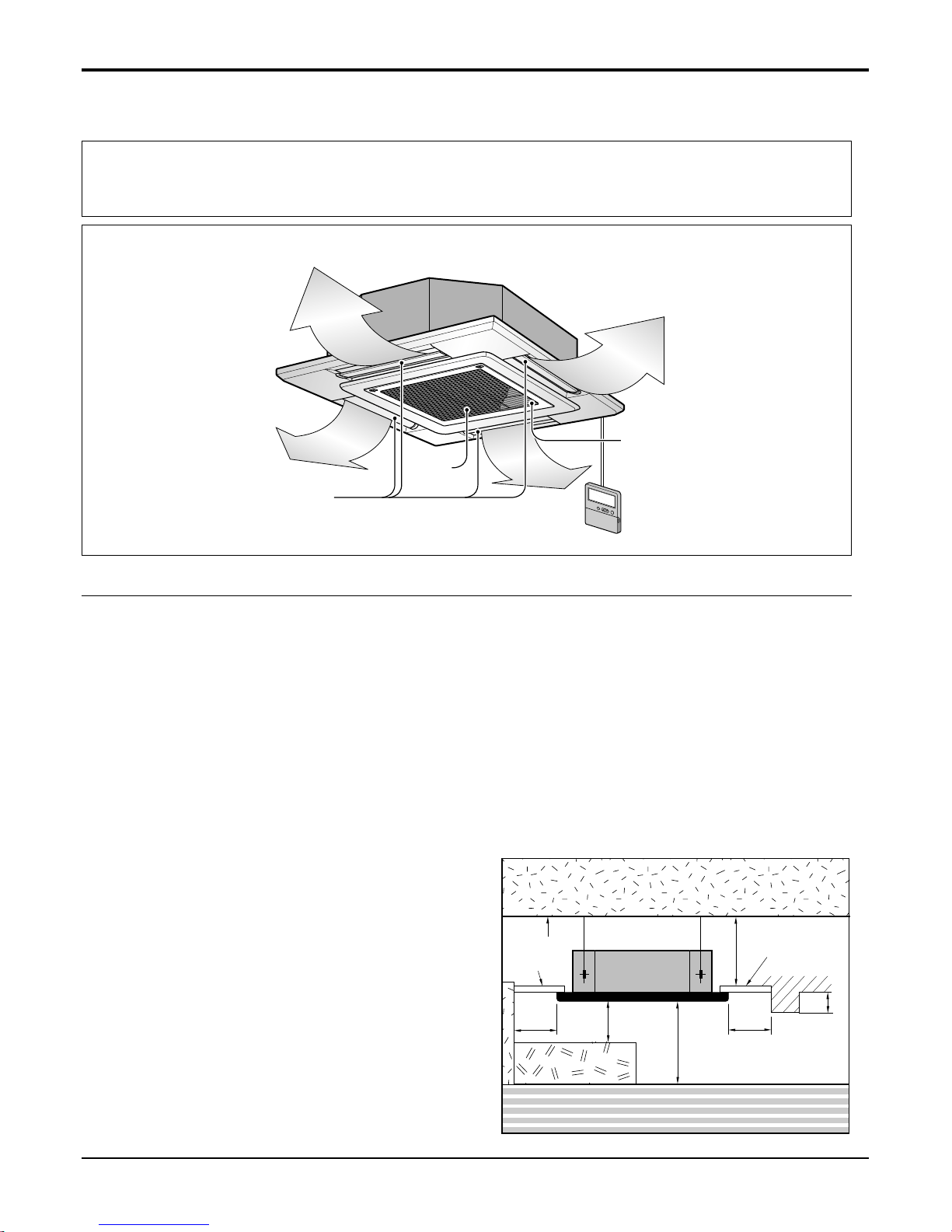
8.1 Selection of the best location
• There should not be any heat source or steam near the
unit.
• There should not be any obstacles to the air circulation.
• There should be provision of easy condensate drain.
• Taking into accounting the noise prevention criteria,
spot the installation location.
• Do not install the unit near the door way.
• Keep proper distances, of the unit, from ceiling, fence,
floor, walls and other obstacles as shown in figure.
• The indoor unit must have the maintenance space.
Unit:cm
Ceiling
Ceiling Board
Ceiling Board
30 or more
Above 250
400 or less
100
or more
50 or
more
50 or
more
30 or less
Floor
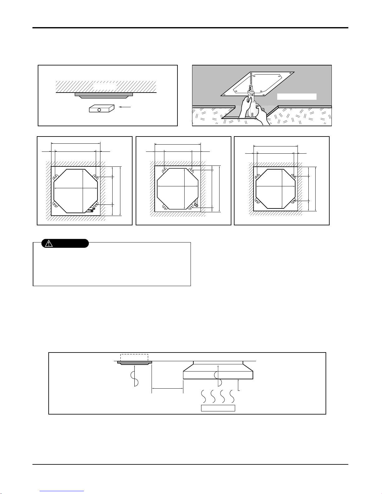
8.2 Ceiling opening dimensions and hanging bolt location
NOTE:
• Avoid the following installation location.
1. Such places as restaurants and kitchen where considerable amount of oil steam and flour is generated.
These may cause heat exchange efficiency reduction, or water drops, drain pump mal-function.
In these cases, take the following actions;
• Make sure that ventilation fan is enough to cover all noxious gases from this place.
• Ensure enough distance from the cooking room to install the air conditioner in such a place where it may not suck oily steam.
Ceiling board
Level gauge
Ceiling
Unit:mm
570 Unit size
570 Unit size
672 (Hanging bolt)
7575
600 (Ceiling opening)
600 (Ceiling opening)
521(Hanging bolt)
39.5
39.5
TE Model TF Model TD Model
Unit:mm
744 Unit size
744 Unit size
658 (Hanging bolt)
6666
790 (Ceiling opening)
790 (Ceiling opening)
572(Hanging bolt)
109
109
Unit:mm
840 Unit size
840 Unit size
672 (Hanging bolt)
101.5101.5
875 (Ceiling opening)
875 (Ceiling opening)
785(Hanging bolt)
45
45
• The dimensions of the paper pattern for installation are the same as those of the ceiling opening dimensions.
• Select and mark the position for fixing bolts and
piping hole.
• Decide the position for fixing bolts slightly tilted to
the drain direction after considering the direction
of drain hose.
• Drill the hole for anchor bolt on the wall.
• This air-conditioner uses a drain pump.
• Install the unit horizontally using a level gauge.
• During the installation, care should be taken not to
damage electric wires.
CAUTION
2. Avoid installng air conditioner in such places where cooking oil or iron powder is generated.
3. Avoid places where inflammable gas is generated.
4. Avoid place where noxious gas is generated.
5. Avoid places near high frequency generators.
Use the ventilation fan
for smoke-collecting
hood with sufficient
capacity.
Cooking table
Air conditioner
Take enough
distance
26 Universal System Air Conditioner
Ceiling Cassette 4-way
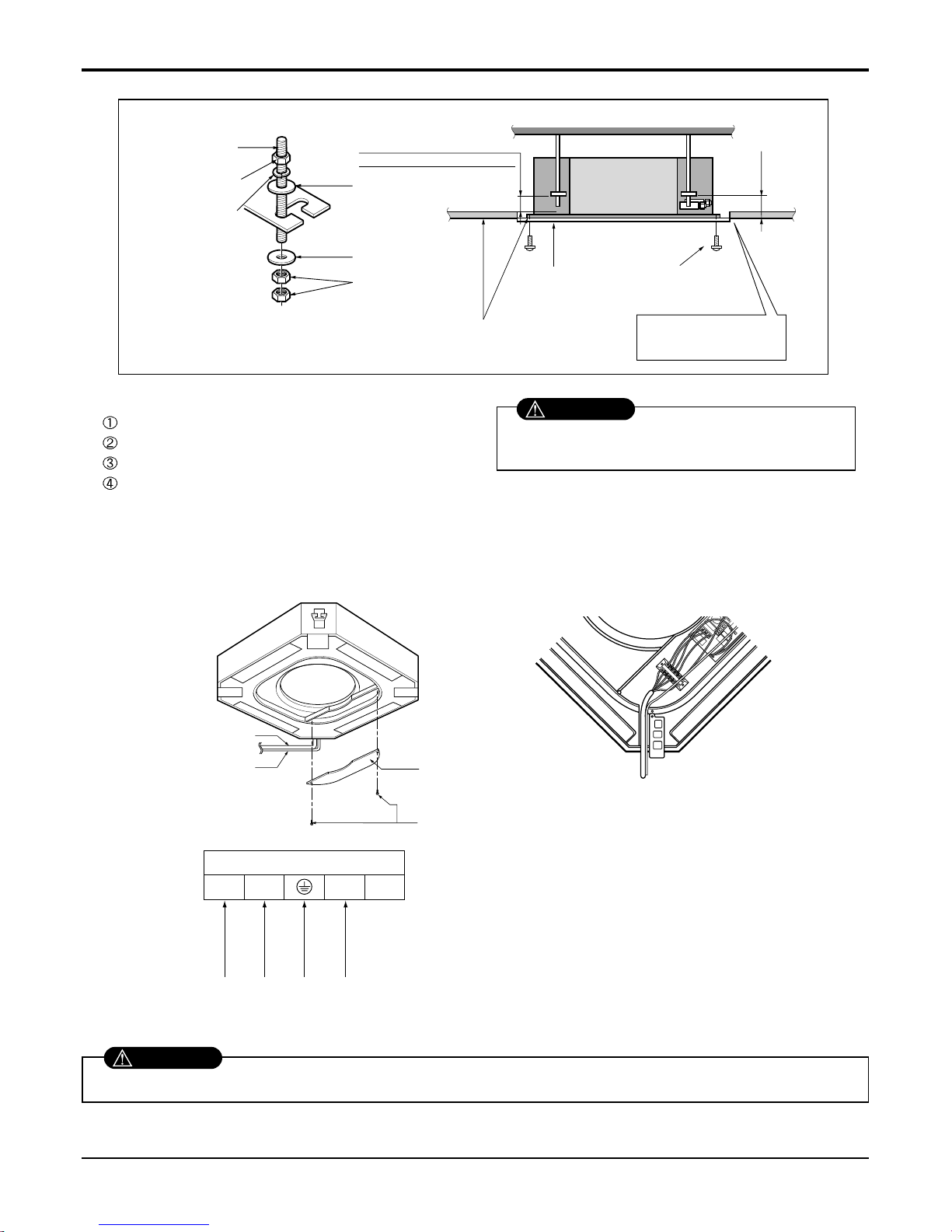
Service Manual 27
Ceiling Cassette 4-way
Set screw of
paper pattern (4 pieces)
Paper pattern
for installation
Ceiling board
150mm
Adjust the same height
Ceiling board
Ceiling
Flat washer for M10
(accessory)
Keep the length of the bolt
from the bracket to 40mm
Open the ceiling board
along the outer edge of the
paper pattern.
Flat washer for M10
(accessory)
Hanging bolt
(W3/8 or M10)
Nut
(W3/8 or M10)
Nut
(W3/8 or M10)
Spring washer
(M10)
Air Conditioner body
• The following parts are local purchasing.
Hanging Bolt - W 3/8 or M10
Nut - W 3/8 or M10
Spring Washer - M10
Plate Washer - M10
• Tighten the nut and bolt to prevent unit from
falling off.
CAUTION
[Air inlet side view]
Control box cover
Indoor
power cord
Remote
controller
cord
Control box cover
fitting screw(2 units)
Terminal Block in Indoor
1(L) 2(N) 3 4
Connected to outdoor unit
8.3 Wiring Connection
• Open the control box cover and connect the remote control cord and Indoor power wires.
Make sure that the screws of the terminal are free from looseness.
WARNING
28 Universal System Air Conditioner
Ceiling Cassette 4-way
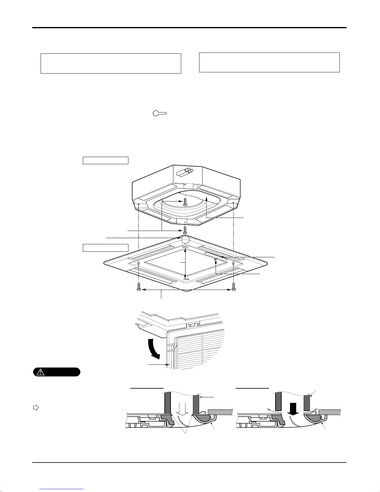
8.4 Installation of Decoration Panel
1. Temporarily fix two decoration panel fixing screws (hexagon M5 screw) on the unit body. (Tighten by
amount 10mm in length.)
The fixing screws (hexagon M5 screw) are included the indoor unit box.
2. Remove the air inlet grille from the decoration panel. (Remove the hook for the air inlet grille cord.)
3. Hook the decoration panel key hole ( ) on the screws fixed in step above, and slide the panel so
that the screws reach the key hole edge.
4. Retighten completely two temporarily fixed screws and other two screws. (Total 4 screws)
5. Connect the louver motor connector and display connector.
6. After tightening these screws, install the air inlet grille (including the air filter).
Decoration panel fixing screws
(hexagon M5 screws)
Temporally fitting at 2 places
(Tightening about 10mm)
Control box cover
Piping side
Inlet GrilleInlet GrilleInlet Grille
Inlet GrilleInlet Grille
Louver motor
Decoration panel fixing screws
(Hexagon M5 screw)
Air conditioner unit
Decoration panel
Key holes
Display
Lead wire for
louver motor and
display
The decoration panel has its installation
direction.
Before installing the decoration panel,
always remove the paper template.
CAUTION
Install certainly the decoration
panel.
Cool air leakage causes sweating.
Water drops fall.
Air conditioner
unit
Ceiling
board
Decoration panel
Decoration
panel
Fit the insulator (this part) and
be careful for cool air leakage
Good example
Air
Cool air leakage
(no good)
Bad example
Ceiling
board
Air conditioner unit
Service Manual 29
Ceiling Cassette 4-way
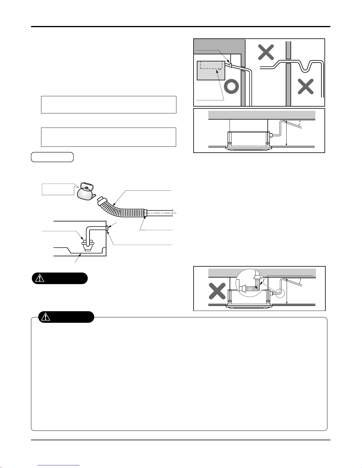
8.5 Indoor Unit Drain Piping
• Drain piping must have down-slope (1/50 to 1/100): be sure
not to provide up-and-down slope to prevent reversal flow.
• During drain piping connection, be careful not to exert extra
force on the drain port on the indoor unit.
• The outside diameter of the drain connection on the indoor
unit is 32mm.
•
Be sure to install heat insulation on the drain piping.
Piping material: Polyvinyl chloride pipe VP-25
and pipe fittings
The air conditioner uses a drain pump to drain water.
Use the following procedure to test the drain pump operation:
• Connect the main drain pipe to the exterior
and leave it provisionally until the test
comes to an end.
• Feed water to the flexible drain hose and
check the piping for leakage.
• Be sure to check the drain pump for normal
operating and noise when electrical wiring
is complete.
• When the test is complete, connect the
flexible drain hose to the drain port on the
indoor unit.
Heat insulation material: Polyethylene foam with
thickness more than 8 mm.
Drain test
Maintenance
drain port
Upward
routing
not allowed
Pipe clamp
Indoor unit
1/50~1/100
MAX 700mm
Feed water
Drain Pump
Drain pan
Flexible drain hose
(accessory)
Main
drain pipe
Glue the joint
Drain
port
Drain hose connection
Use the clip (accessory)
CAUTION
The supplied flexible drain hose should not be curved,
neither screwed. The curved or screwed hose may
cause a leakage of water.
1/50~1/100
MAX 700mm
Flexible drain hoseFlexible drain hose
After the confirmation of the above conditions, prepare the wiring as follows:
1) Never fail to have an individual power specialized for the air conditioner. As for the method of wiring, be guided by the
circuit diagram pasted on the inside of control box cover.
2) Provide a circuit breaker switch between power source and the unit.
3) The screw which fasten the wiring in the casing of electrical fittings are liable to come loose from vibrations to which the
unit is subjected during the course of transportation. Check them and make sure that they are all tightly fastened. (If they
are loose, it could give rise to burn-out of the wires.)
4) Specification of power source
5) Confirm that electrical capacity is sufficient.
6) Be sure that the starting voltage is maintained at more than 90 percent of the rated voltage marked on the name plate.
7) Confirm that the cable thickness is as specified in the power sources specification.
(Particularly note the relation between cable length and thickness.)
8) Never fail to equip a leakage breaker where it is wet or moist.
9) The following troubles would be caused by voltage drop-down.
• Vibration of a magnetic switch, damage on the contact point there of, fuse breaking, disturbance to the normal function of a
overload protection device.
• Proper starting power is not given to the compressor.
CAUTION
30 Universal System Air Conditioner
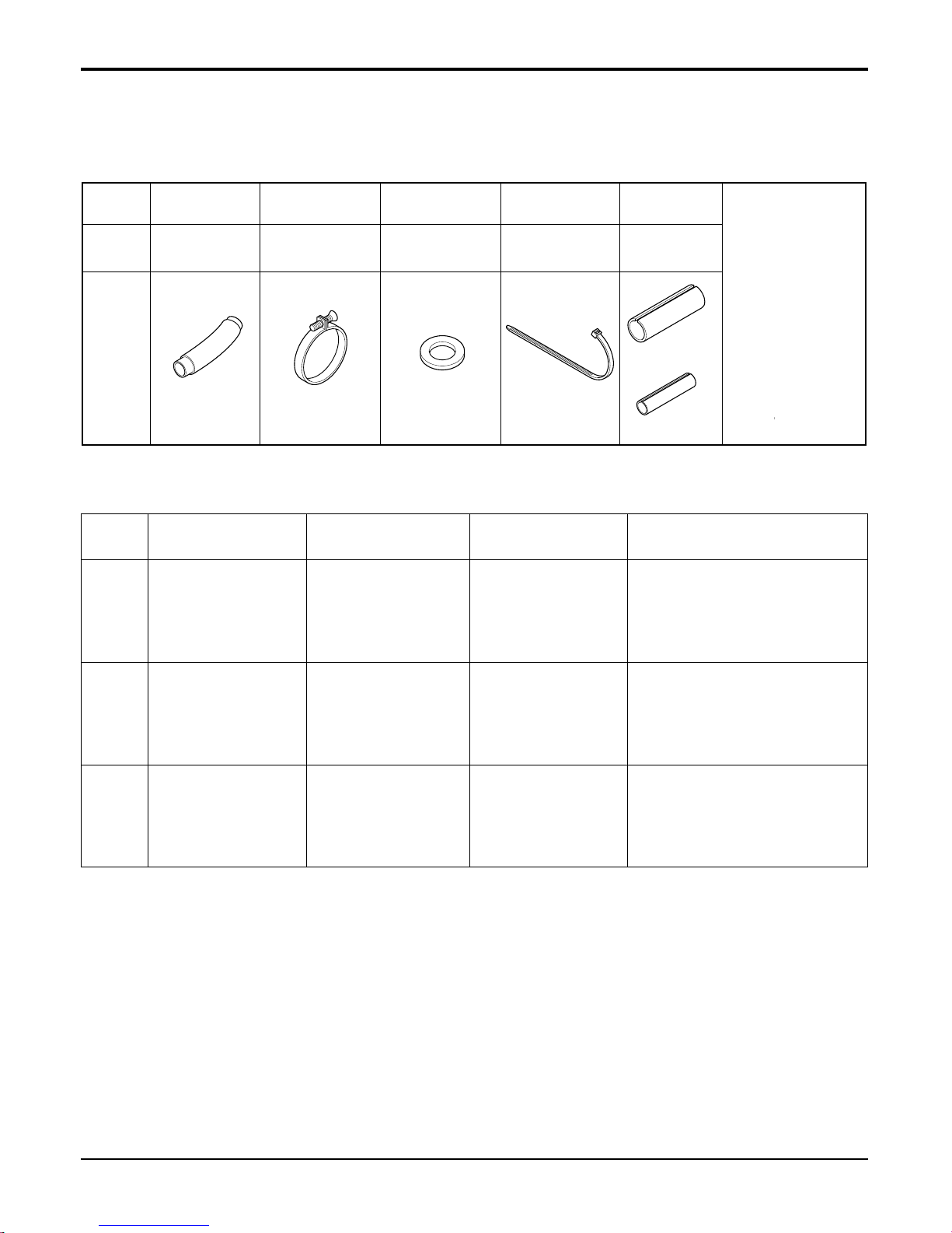
Ceiling Cassette 4-way
Name
Quantity
Shape
for gas pipe
for liquid pipe
Clamp metal
1 EA
Insulation for
fitting
1 SET
Drain hose
1 EA
Clamp
8 EA
Washer for
hanging backet
8 EA
(Other)
Optional Accessories(For Unit)
Standard Accessories
• Paper pattern for
installation
• Owner's manual
• Installation manual
No. Item Type Model No.
Component Parts
• Wireless remote control : 1EA
• Holder : 1EA
• Battery : 2EA
• Screw : 2EA
• Central control
• Installation manual
• PCB: 1EA
• Installation manual
• Wire assembly
1
2
3
Wireless remote
control
With air purifying
function
AHWRHD
Central control Simple PQCSA101S0
PI485 Gateway For central control PHNFP14A0
9. Accessories
 Loading...