

LG ARNU07GSFV2 INSTALLATION INSTRUCTIONS

INSTALLATION MANUAL
AIR CONDITIONER
• Please read this installation manual completely before installing the product.
• Installation work must be performed in accordance with the national wiring
standards by authorized personnel only.
• Please retain this installation manual for future reference after reading
it thoroughly.
P/NO : MFL42803112
www.lg.com
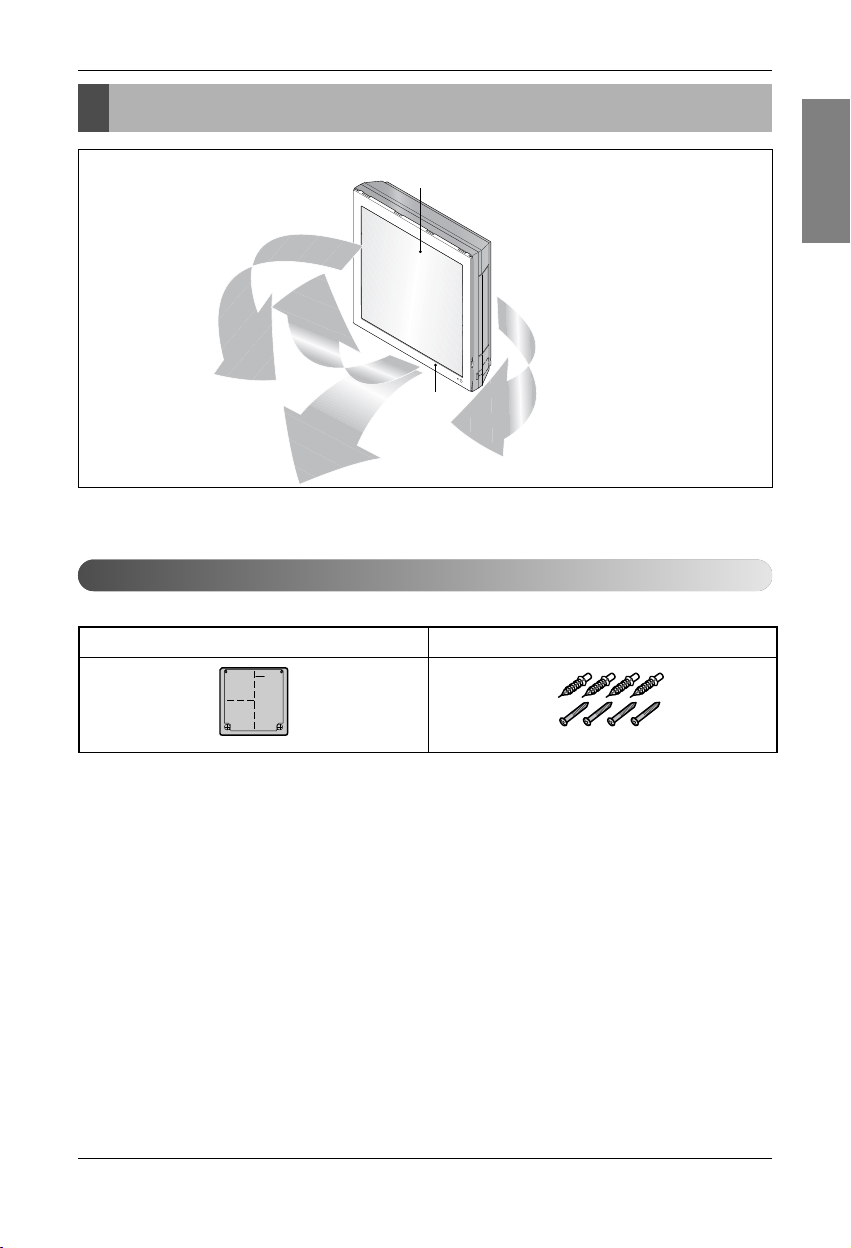
TYPE: Art Cool Gallery Series
ENGLISH
ITALIANO
ESPAÑOL
FRANÇAIS DEUTSCH
PORTUGUÊS
кмллдавьбхд

2 Indoor Unit
Art Cool Type Indoor Unit Installation Manual
TABLE OF CONTENTS
Installation Requirements
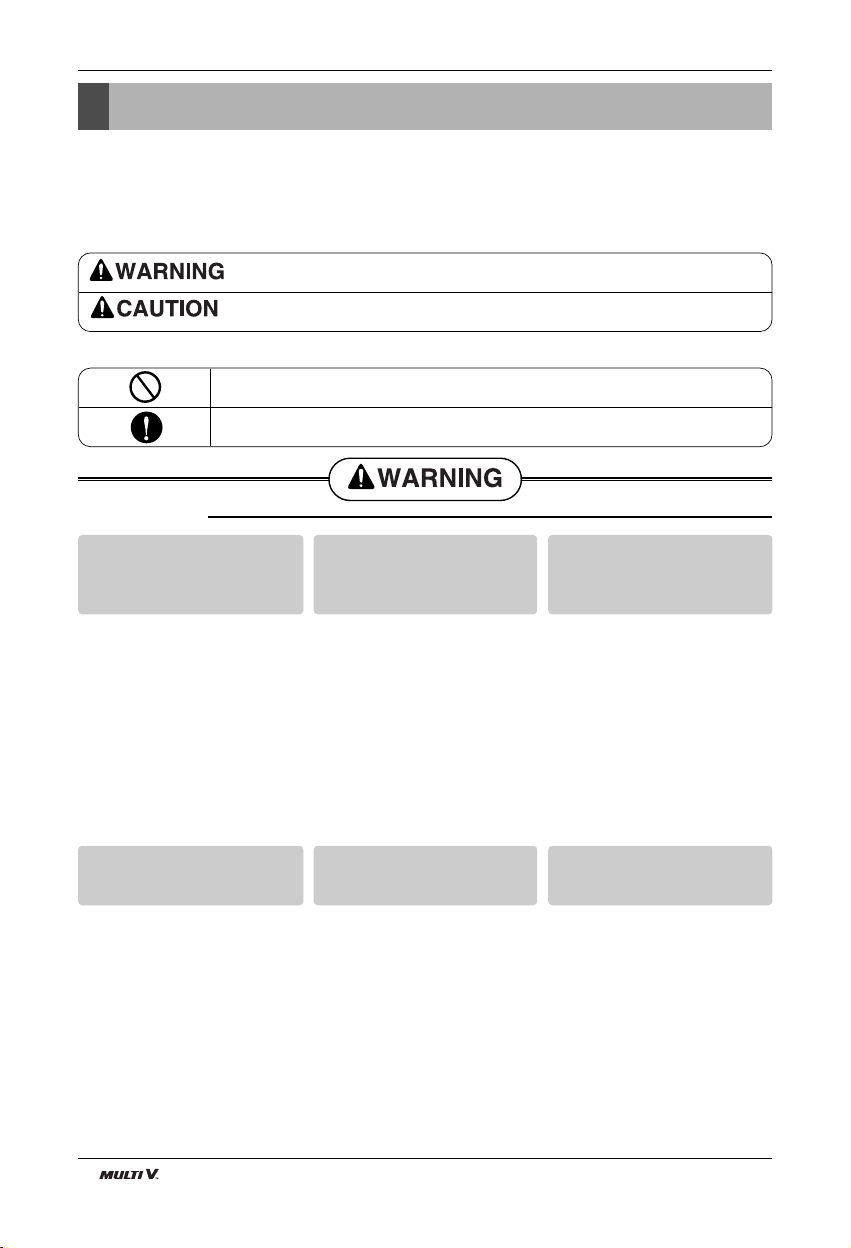
Required Parts Required Tools
❏ Pipes: Gas side
Liquid side
(Refer to Product
Data)
❏ Insulation materials
❏ Additional drain pipe
❏ Installation guide map
❏ Four type "A" screws & plastic
anchors
❏ Connecting cable
❏ Level gauge
❏ Screw driver
❏ Electric drill
❏ Hole core drill
❏ Horizontal meter
❏ Flaring tool set
❏ Specified torque wrenches
(different depending on model No.)
❏ Spanner .......Half union
❏ A glass of water
❏ Screw driver
❏ Hexagonal wrench
❏ Gas-leak detector
❏ Vacuum pump
❏ Gauge manifold
❏ Owner's manual
❏ Thermometer
❏ Holder Remote Controller
Installation Parts ....................3
Safety Precautions.................4
Installation
Selection the best location ....7
Preparing Work for Installation
................................................8
Fixing Indoor Unit...................9
Drill a Hole in the Wall ...........9
Flaring Work.........................10
Connecting the Piping .........11
Drain Piping .........................13
Panel Front Assembly .........14
Wiring Connection ...............15
Installation of Wireless
Remote Controller ...............16
Installation of Wired Remote
Controller..............................17
Name and function of wired
remote controller(Accessory)
..............................................19
Group Control Setting..........20
❏ Two type "B" screws
Installation Manual 3
Installation Parts
ENGLISH
Installation Parts
Air Intake
Air Outlet
Type "A" screw and plastic anchor
Installation guide map
Installation Parts
Read carefully, and then follow step by step.
4 Indoor Unit
Safety Precautions
Safety Precautions
To prevent injury to the user or other people and property damage, the following instructions must be followed.
■ Be sure to read before installing the air conditioner.
■ Be sure to observe the cautions specified here as they include important items related to safety.
■ Incorrect operation due to ignoring instruction will cause harm or damage. The seriousness is classified by the
following indications.
■ Meanings of symbols used in this manual are as shown below.
This symbol indicates the possibility of death or serious injury.
This symbol indicates the possibility of injury or damage to properties only.
Be sure not to do.
Be sure to follow the instruction.
■ Installation
Do not use a defective or underrated circuit breaker. Use this
appliance on a dedicated circuit.
• There is risk of fire or electric shock.
For electrical work, contact the
dealer, seller, a qualified electrician, or an Authorized Service
Center.
• Do not disassemble or repair the
product. There is risk of fire or electric shock.
Always ground the product.
• There is risk of fire or electric shock.
Install the panel and the cover
of control box securely.
• There is risk of fire or electric shock.
Always install a dedicated circuit and breaker.
• Improper wiring or installation may
cause fire or electric shock.
Use the correctly rated breaker
or fuse.
• There is risk of fire or electric shock.

Installation Manual 5
Safety Precautions
ENGLISH
n Operation
Do not modify or extend the
power cable.
• There is risk of fire or electric shock.
Do not let the air conditioner
run for a long time when the
humidity is very high and a door
or a window is left open.
• Moisture may condense and wet or
damage furniture.
Be cautious when unpacking
and installing the product.
• Sharp edges could cause injury. Be
especially careful of the case edges
and the fins on the condenser and
evaporator.
For installation, always contact
the dealer or an Authorized
Service Center.
• There is risk of fire, electric shock,
explosion, or injury.
Do not install the product on a
defective installation stand.
• It may cause injury, accident, or
damage to the product.
Be sure the installation area
does not deteriorate with age.
• If the base collapses, the air conditioner could fall with it, causing property damage, product failure, and
personal injury.
Do not store or use flammable gas or combustibles near the product.
• There is risk of fire or failure of product.
Use a vacuum pump or Inert (nitrogen) gas when doing leakage test or air purge. Do not compress air or Oxygen
and do not use Flammable gases. Otherwise, it may cause fire or explosion.
• There is the risk of death, injury, fire or explosion.
6 Indoor Unit
Safety Precautions
Always check for gas (refrigerant) leakage after installation or
repair of product.
• Low refrigerant levels may cause
failure of product.
Install the drain hose to ensure
that water is drained away properly.
• A bad connection may cause water
leakage.
Keep level even when installing
the product.
• To avoid vibration or water leakage.
Do not install the product where
the noise or hot air from the outdoor unit could damage the
neighborhoods.
• It may cause a problem for your
neighbors.
Use two or more people to lift
and transport the product.
• Avoid personal injury.
Do not install the product where
it will be exposed to sea wind
(salt spray) directly.
• It may cause corrosion on the product.
Corrosion, particularly on the condenser and evaporator fins, could
cause product malfunction or inefficient
operation.
■ Installation
If you eat the liquid from the
batteries, brush your teeth and
see doctor. Do not use the
remote if the batteries have
leaked.
• The chemicals in batteries could
cause burns or other health
hazards.
The Power cord connected to the
unit should be selected according to the following specifications.
Installation Manual 7
Installation
ENGLISH
Read completely, then follow step by step.
Installation
Selection of the best location
CAUTION : In case that the unit is installed near the sea, the installation parts
may be corroded by salt. The installation parts (and the unit) should be taken
appropriate anti-corrosion measures.
• Do not have any heat or steam near the unit.
• Select a place where there are no obstacles in front of the unit.
• Make sure that condensation drainage can be conveniently routed away.
Do not install near a doorway.
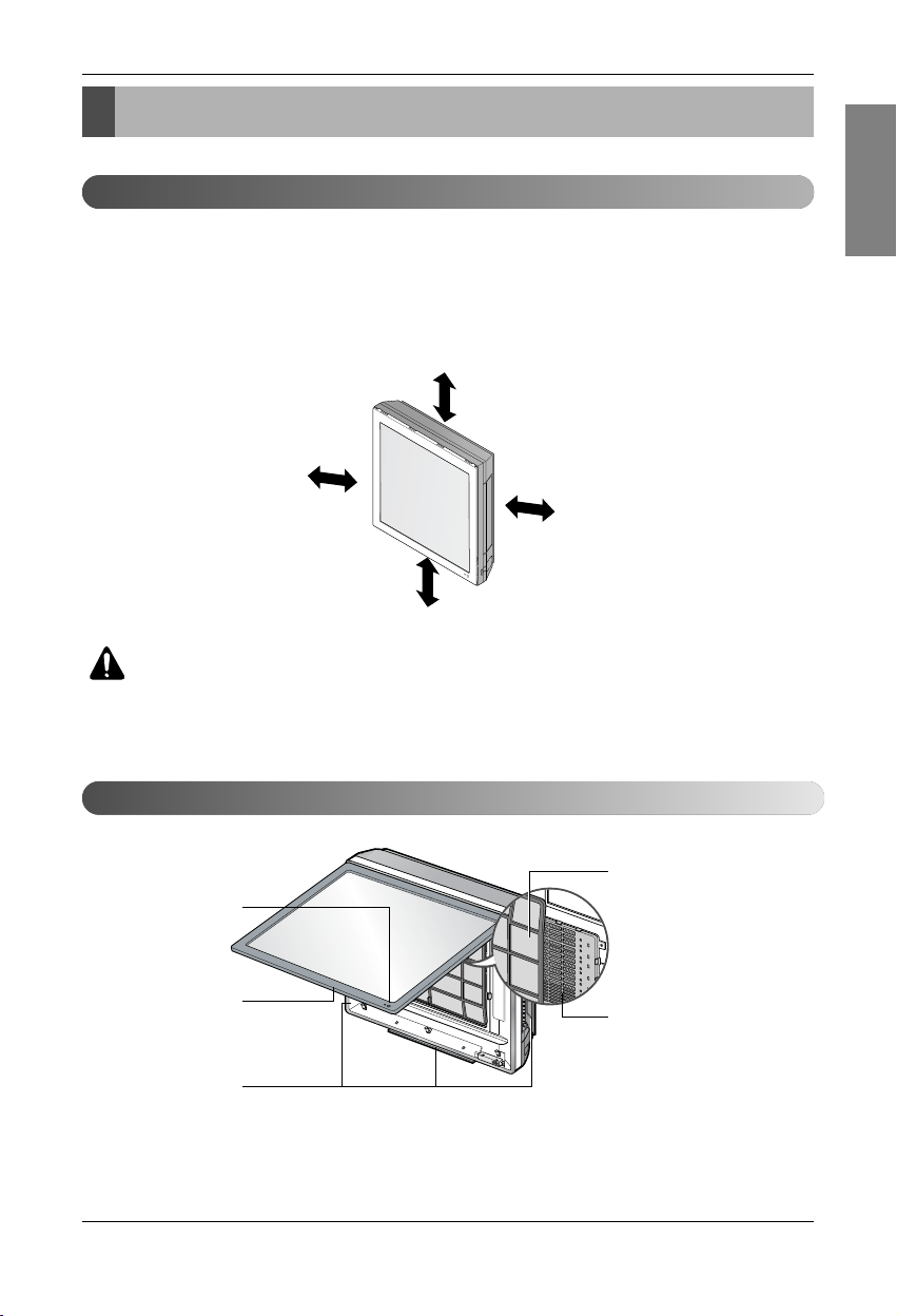
• Ensure that the space around the left and right of the unit is more than 50cm. The unit should be installed as high on the
wall as possible, allowing a minimum of 10cm from ceiling.
• Use a stud finder to locate studs to prevent unnecessary damage to the wall.
More than 200mm(Minimum)
More
than 500mm
More than 1.5m
More
than 500mm
Signal Receptor
Front Panel
Air Discharge
Air Filter
Plasma Filter
Features
8 Indoor Unit
Installation
Preparing Work for Installation
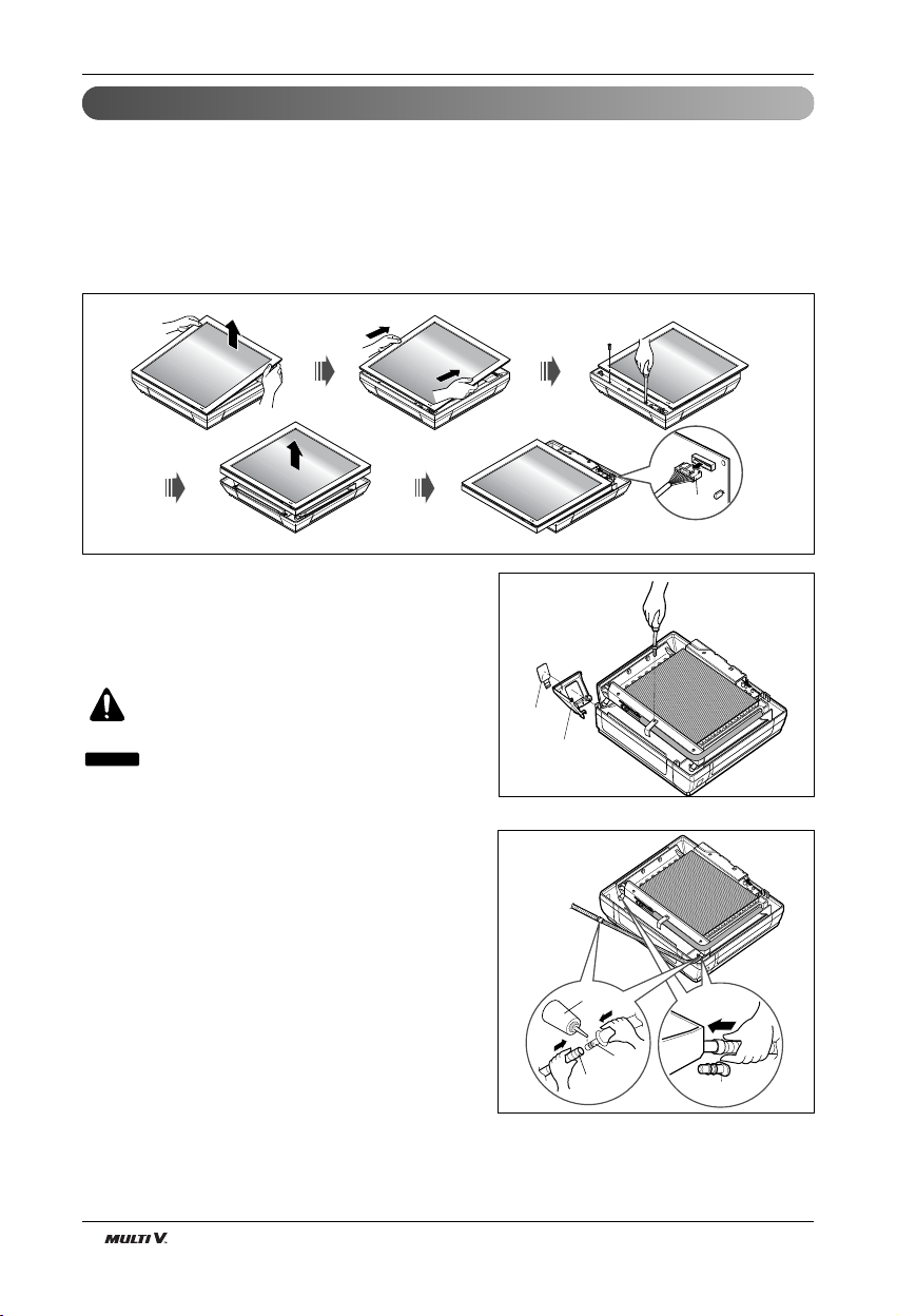
Open panel front
1. Pull the upper part of the front panel.
2. Lift up the panel.
3. To detach the front panel, remove the two screws at the lower part.
4. Detach the front panel from the body.
5. To detach the panel, disconnect the connector at the upper part.
Cover pipe and cover side remove
1. Please remove the screw of the center tuning cover.
2. Pull up the side cover of desired connecting direction, then
cover side is separated.
3. Pick the pipe hole of the side cover.
CAUTION: After removing the pipe hole,
cut the burr for safety.
When making pipe path through rear
wall, you don’t need to pick the pipe hole.
NOTICE
Drain hose junction
1. Remove the rubber stopple in the desired drain
direction.
2. Insert drain hose into the handle of drain pan, and
join drain hose and connecting hose according to
the figure by.
Panel Front
Connector
Side cover
Pipe hole
Only the
desired direction
rubber cap
Only the
desired direction
Connecting
part
Adhesive
Drain
hose
Installation Manual 9
Installation
ENGLISH
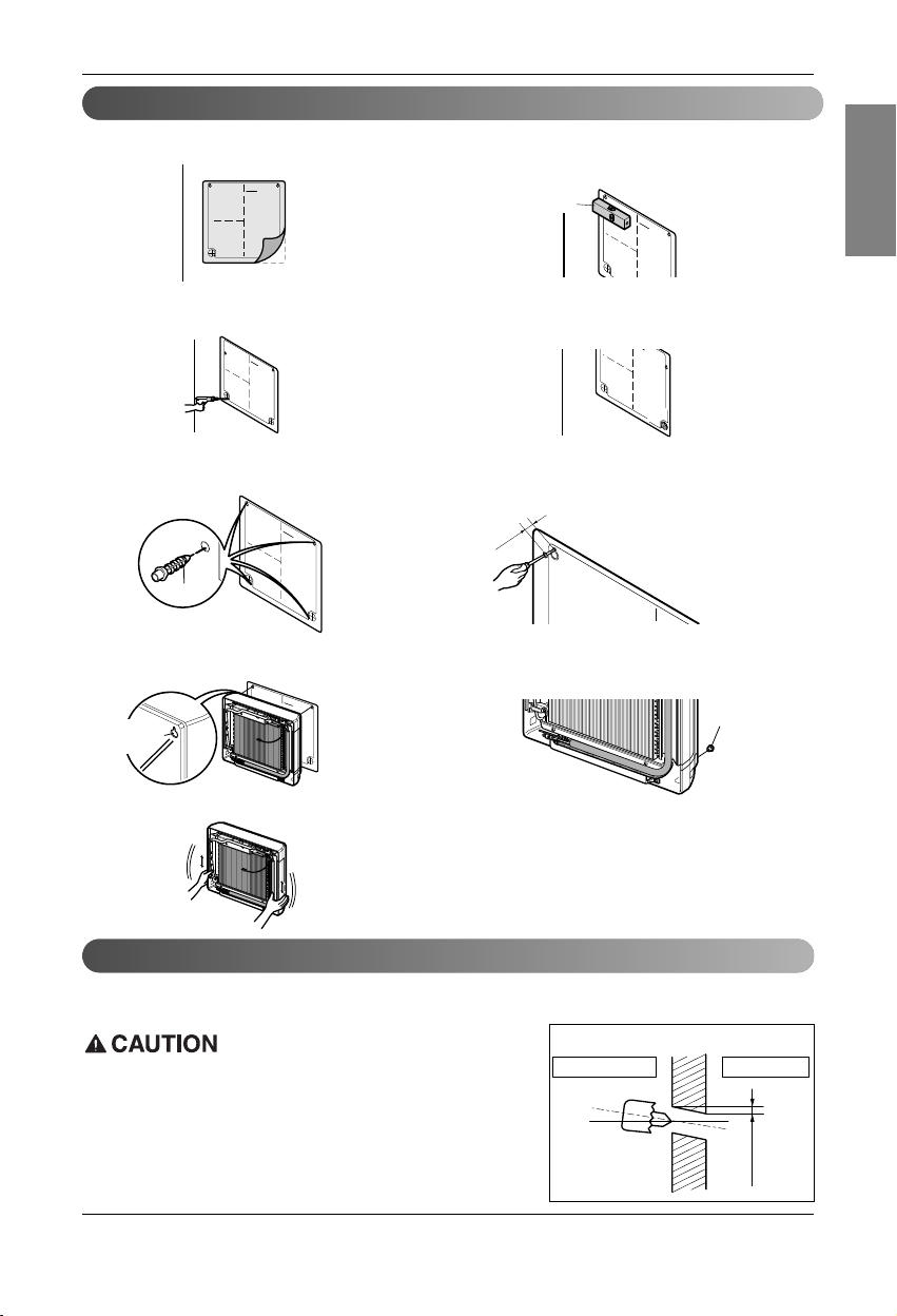
Fixing Indoor Unit
• Drill the piping hole with a ø50mm hole core drill. Drill the piping hole at either the right or the left with the hole
slightly slanted to the outdoor side.
5-7mm
(0.2~0.3")
Indoor
WALL
Outdoor
Plastic anchors
INSTALLATION GUIDE MAP
10mm
INSTALLATION GU
Plastic anchors
INST
ALLA
TION GU
I
D
E MA
P
I
N
STALLA
TION
GU
IDE
M
A
P
Hanger hole
(Rear side of
the product)
I
N
S
T
AIIATION
GUI
D
E
MA
P
3. Make a hole with a diameter of 6mm and
depth of 30-35mm by piercing a screw
point.
5. Drive the fore plastic anchors into drilled
points.
7. Hang the hole of product at the upper
screws, and remove the map. (Falling
attention)
9. Check the fixed product with light power.
1. Attach an Installation guide map on the
desired surface.
2. Look at suited horizon by horizontal
meter on the horizontal setting line, and
fix lightly the map by adhesive tape.
4.
Drill the pierted part as a diameter of 50mm
for connecting piping. (In case of piercing
rear surface)
6.
First, Drive the two points of the upper
parts by screws. (Leave 10mm for hanging
the product)
8. Drive the lower parts after facing the hole
of product with plastic anchors, and fix
completely the upper screws.
10.
In case of nothing wrong, connect the
pipe and the wire. (Refer to installation
manual)
I
If the split type Indoor unit is installed in a wall having hole or opening near by or back side of the unit, then the air from other side of
the wall can come inside the condition space through that hole/
opening. That air can cause unwanted dew/ water droplet formation
when it comes in contact with body of the indoor unit. So all hole or
opening on the wall must be blocked very well to avoid water dropping from the body of the unit.
Drill a Hole in the Wall
Horizontality
NST
A
LL
A
TIO
N
G
U
I
D
E
MA
P
 Loading...