

LG 42LT76-ZA, 37LT76, 32LT76, 42LT76 User Manual
ENGLISH
LCD TV |
PLASMA TV |
OWNER’S MANUAL |
|
LCD TV MODELS |
PLASMA TV MODELS |
32LT7* |
42PT8* |
37LT7* |
50PT8* |
42LT7* |
|
Please read this manual carefully before operating your TV.
Retain it for future reference.
Record model number and serial number of the TV. Refer to the label on the back cover and quote this information.
To your dealer when requiring service.
Trademark of the DVB Digital Video
Broadcasting Project (1991 to 1996)
ID Number(s): 4652: 42PT85 |
4651: 50PT85 |
4681: 32LT75 |
4680: 37LT75 |
4679: 42LT75 |
5502: 32LT76 |
5503: 37LT76 |
5504: 42LT76 |
|
|
|
|
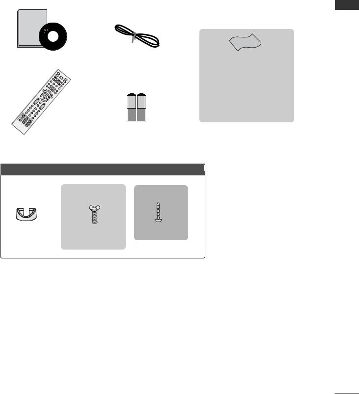
ACCESSORIES
Ensure that the following accessories are included with your TV. If an accessory is missing, please contact the dealer where you purchased the TV.
Owner's |
|
Manual |
|
Owner’s manual |
|
Owner’s Manual |
Power Cord |
|
|
|
IN |
|
|
|
|
|
PU |
|
|
|
|
|
D/A T |
|
|
|
TV/RAD |
P |
|
|
|
|
INPUT |
IO |
OW |
|
|
|
|
ER |
MO |
||
LINK |
T |
|
BRIGHT |
||
|
TV |
DE |
|||
SIMP |
|
|
|
|
|
|
EXT |
|
DVD |
|
|
IN |
VCR |
FOi |
|
|
LIVETV |
|
|
|
|
|
|
XIT |
BACK |
|
|
|
|
|
|
E |
|
|
|
|
|
|
|
|
D |
|
|
|
|
|
|
STIME |
VR |
|
|
|
|
|
|
M |
|
|
|
|
|
|
|
HIFT |
ENU |
|
|
|
|
|
|
OK |
G |
|
|
|
|
|
|
UIDE |
|
|
|
|
|
|
|
|
TI |
|
|
|
|
|
V |
MARK |
SHME |
|
|
|
|
|
OL |
IFT |
|
|
|
|
|
|
|
FAV |
|
|
|
|
|
1 |
MUTE |
PR |
|
|
|
|
4 |
|
|
||
|
|
|
|
2 |
|
|
|
|
|
|
7 |
5 |
|
3 |
|
|
|
|
|
|
|
||
|
|
L |
|
|
|
|
|
|
|
IST |
|
8 |
6 |
|
|
|
UPDATE |
|
0 |
|
9 |
|
|
S |
|
|
Q. |
|
|
|
|
|
|
|
|
|
|
||
LEEP |
INDEX |
|
VIEW |
|
|
|
|
SUBTITLE |
|
|
|
|
|
|
|
HO |
TIME |
|
|
|
|
||
|
RATIO |
LD |
|
|
|
|
|
|
REVEAL |
|
|
|
|
||
|
|
I/II |
|
|
|
|
|
Batteries
Remote Control
Polishing Cloth
Polishing cloth for use on the screen This feature is not available
for all models.
*Lightly wipe any stains or fingerprints on the surface of the TV with the polishing cloth.
Do not use excessive force. This may cause scratching or discolouration.
LCD TV models
32/37LT7* only
32/37LT7* only
|
|
1-screw for stand fixing |
Cable Management |
4-bolts for stand assembly |
Refer to p. 9 |
|
Refer to p. 9 |
|
ACCESSORIES
1

CONTENTS
|
ACCESSORIES . . . . . . . . . . . . . . . . . . . . . . . . . . . . . . . . . . . . . . . . . . . |
. . 1 |
|
PREPARATION |
|
CONTENTS |
Back Panel Information . . . . . . . . . . . . . . . . . . . . . |
. 7 |
|
Home Menu . . . . . . . . . . . . . . . . . . . . . . . . . . . . . . |
. 4 |
|
Front Panel Controls . . . . . . . . . . . . . . . . . . . . . . . |
. 5 |
|
Stand installation . . . . . . . . . . . . . . . . . . . . . . . . . . . |
. 9 |
|
ATTACHING THE TV TO A DESK (Only 32/37LT7* model) |
. . .9 |
|
Attaching the TV to a wall . . . . . . . . . . . . . . . . . . . . |
10 |
|
Back Cover for Wire Arrangement . . . . . . . . . . . . . |
11 |
|
Desktop Pedestal Installation . . . . . . . . . . . . . . . . . |
13 |
|
Wall Mount: Horizontal installation . . . . . . . . . . . . |
13 |
|
Antenna Connection . . . . . . . . . . . . . . . . . . . . . . . . |
14 |
|
EXTERNAL EQUIPMENT SETUP |
|
|
HD Receiver Setup . . . . . . . . . . . . . . . . . . . . . . . . |
15 |
|
DVD Setup . . . . . . . . . . . . . . . . . . . . . . . . . . . . . . . . |
17 |
|
Insertion of CI module . . . . . . . . . . . . . . . . . . . . . . |
19 |
|
VCR Setup . . . . . . . . . . . . . . . . . . . . . . . . . . . . . . . . |
20 |
|
Digital Audio Out Setup . . . . . . . . . . . . . . . . . . . . . |
22 |
|
Other A/V Source Setup . . . . . . . . . . . . . . . . . . . . |
23 |
|
PC Setup . . . . . . . . . . . . . . . . . . . . . . . . . . . . . . . . . |
24 |
|
- Screen Setup for PC Mode . . . . . . . . . . . . . . . |
27 |
WATCHING TV / PROGRAMME CONTROL
Remote Control Key Functions . . . . . . . . . . . . . . . . 31 Turning on the TV . . . . . . . . . . . . . . . . . . . . . . . . . . 33 Programme Selection . . . . . . . . . . . . . . . . . . . . . . . 34 Volume Adjustment . . . . . . . . . . . . . . . . . . . . . . . . 34 On-Screen Menus Selection and Adjustment . . . . 35 Auto Programme Tuning (In Digital Mode) . . . . . . 36 Manual Programme Tuning (In Digital Mode) . . . . 37 Programme Edit (In Digital Mode) . . . . . . . . . . . . . 38 5V antenna Power (In Digital Mode only) . . . . . . . 40 Booster (In Digital Mode only) . . . . . . . . . . . . . . . 40 Software Update (In Digital Mode only) . . . . . . . . 41 Diagnostics (In Digital Mode only) . . . . . . . . . . . . 42
CI Information (In Digital Mode only) . . . . . . . . . . 43 Auto Programme Tuning (In Analogue Mode) . . . . . 44 Manual Programme Tuning (In Analogue Mode) . . . . . . . 45 Fine Tuning (In Analogue Mode) . . . . . . . . . . . . . . 46 Assigning a Station Name (In Analogue Mode) . . . . . . 46 Programme Edit (In Analogue Mode) . . . . . . . . . . . . . 47 Selecting the Programme Table . . . . . . . . . . . . . . 49 Input Source Selection . . . . . . . . . . . . . . . . . . . . . 50 SIMPLINK Function . . . . . . . . . . . . . . . . . . . . . . . . . 51
DVR (DIGITAL VIDEO RECORDER)
TimeShift Mode ( Pause & Replay of Live TV) . . . 53
Instant Recording . . . . . . . . . . . . . . . . . . . . . . . . . . 56
Manual Recording . . . . . . . . . . . . . . . . . . . . . . . . . . 59
Recorded TV Programme List . . . . . . . . . . . . . . . . . 60
Schedule List . . . . . . . . . . . . . . . . . . . . . . . . . . . . . . 64
Record Quality . . . . . . . . . . . . . . . . . . . . . . . . . . . . 65
Format Hard Disc . . . . . . . . . . . . . . . . . . . . . . . . . . 66
EPG (Electronic programme guide)(In Digital Mode)
Switch on/off EPG . . . . . . . . . . . . . . . . . . . . . . . . 67 Select programme . . . . . . . . . . . . . . . . . . . . . . . . 67 Button function in NOW/NEXT guide mode . . . 67 Button function in 8 days guide mode . . . . . . . . 68 Button function in date change mode . . . . . . . . 69 Button function in extended description box . . . 69 Record Popup . . . . . . . . . . . . . . . . . . . . . . . . . . . .70 Conflict pop-up . . . . . . . . . . . . . . . . . . . . . . . . . .70
PICTURE CONTROL
Picture Size (Aspect Ratio) Control . . . . . . . . . . . . 71
Preset Picture Settings
- Picture Mode-Preset . . . . . . . . . . . . . . . . . . . . 73
- Auto Colour Tone Control (Warm/Medium/Cool) . . . . .74
Manual Picture Adjustment
- Picture Mode-User option . . . . . . . . . . . . . . . . 75 - Colour Tone - User option . . . . . . . . . . . . . . . .76
2

XD - Picture Improvement Technology . . . . . . . . . . . . . 77
XD Demo . . . . . . . . . . . . . . . . . . . . . . . . . . . . . . . . . 78
Advanced - Cinema . . . . . . . . . . . . . . . . . . . . . . . . . 79
Advanced - Black(Darkness) Level . . . . . . . . . . . . . 80
Picture Reset . . . . . . . . . . . . . . . . . . . . . . . . . . . . . . 81
Image Sticking Minimization(ISM) Method . . . . . . . . . . 82
Low-Power Picture Mode . . . . . . . . . . . . . . . . . . . . 83
SOUND & LANGUAGE CONTROL
Auto Volume Leveler . . . . . . . . . . . . . . . . . . . . . . . . 84 Preset Sound Settings - Sound Mode . . . . . . . . . . 85 Sound Setting Adjustment - User Mode . . . . . . . . . . 86 Balance . . . . . . . . . . . . . . . . . . . . . . . . . . . . . . . . . . . 87 TV Speakers On/ Off Setup . . . . . . . . . . . . . . . . . . 88 Selecting digital audio out . . . . . . . . . . . . . . . . . . . 89 I/II
- Stereo/Dual Reception (In Analogue Mode Only) . . . . 90 - NICAM Reception (In Analogue Mode Only) . . . . . . . 91 - Speaker Sound Output Selection . . . . . . . . . . 91
On-Screen Menus Language/Country Selection . . . . . . . 92 Language selection (In Digital Mode only) . . . . . . 93
TIME SETTING
Clock Setup . . . . . . . . . . . . . . . . . . . . . . . . . . . . . . . 94 Auto On/ Off Timer Setting . . . . . . . . . . . . . . . . . . 95 Auto Shut-off Setting . . . . . . . . . . . . . . . . . . . . . . . 96 Time zone Setup . . . . . . . . . . . . . . . . . . . . . . . . . . . 97 Sleep Timer Setting . . . . . . . . . . . . . . . . . . . . . . . . . 97
PARENTAL CONTROL / RATINGS
Set Password & Lock System . . . . . . . . . . . . . . . . . 98
Parental Control . . . . . . . . . . . . . . . . . . . . . . . . . . . 99
TELETEXT
Switch on/off . . . . . . . . . . . . . . . . . . . . . . . . . . . . . 100 SIMPLE Text . . . . . . . . . . . . . . . . . . . . . . . . . . . . . . 100 TOP Text . . . . . . . . . . . . . . . . . . . . . . . . . . . . . . . . 100 FASTEXT . . . . . . . . . . . . . . . . . . . . . . . . . . . . . . . . 101 Special Teletext Functions . . . . . . . . . . . . . . . . . . . 101
DIGITAL TELETEXT
Teletext within Digital Service . . . . . . . . . . . . . . 102 Teletext in Digital Service . . . . . . . . . . . . . . . . . 102
APPENDIX
Troubleshooting . . . . . . . . . . . . . . . . . . . . . . . . . . . 103
Maintenance . . . . . . . . . . . . . . . . . . . . . . . . . . . . . 105
Product Specifications . . . . . . . . . . . . . . . . . . . . . 106
Programming the Remote Control . . . . . . . . . . . . 107
IR Codes . . . . . . . . . . . . . . . . . . . . . . . . . . . . . . . . 109
External Control Device Setup . . . . . . . . . . . . . . . 111
CONTENTS
3
PREPARATION
PREPARATION
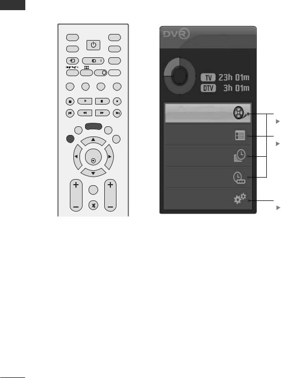
HOME MENU
This menu is a contents guide.
In the Home Menu, you can access the Recorded list of the DVR, Manual Recording of the DVR, Schedule List or the TV Menu.
INPUT |
|
MODE |
D/A |
POWER |
TV |
TV/RADIO |
|
DVD |
INPUT |
BRIGHT |
|
|
|
VCR |
SIMPLINK |
TEXT INFO i |
LIVE TV |
BACK |
DVR |
MENU |
|
|
|
EXIT |
|
GUIDE |
TIME |
OK |
TIME |
SHIFT |
|
SHIFT |
|
MARK |
|
|
FAV |
|
VOL |
|
PR |
|
MUTE |
|
Home
Free Space
This displays the remaining record time for analogue input. (Analog
 TV, AV1,AV2, AV3)
 This displays the remaining record time for DTV input.
Recorded TV |
DVR |
|
p.53 |
Programme Guide |
EPG |
|
p.67 |
Schedule List |
|
Manual Record |
|
TV Menu |
TV Menu |
|
|
|
p.35 |
4
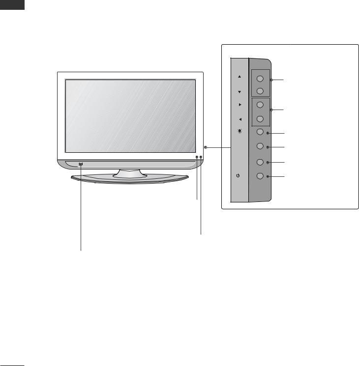
FRONT PANEL CONTROLS
AThis is a simplified representation of the front panel. Image shown may differ from your TV.
AIf your TV has a protection film attached, remove the film and then wipe the TV with a polishing cloth.
Plasma TV Models
Remote Control Sensor |
Power/Standby Indicator
• illuminates red in standby mode.
• illuminates green when the TV is switched on.
PREPARATION
INPUT |
MENU |
OK |
VOL |
PR |
|
|
|
|
|
|
|
|
|
|
|
|
|
|
|
|
POWER |
INPUT |
MENU |
OK |
VOLUME |
|
|
|
|
PROGRAMME |
||||||
|
|
|
|
|
|
|
|
5
PREPARATION
PREPARATION
LCD TV Models
PR |
PROGRAMME |
|
|
VOL |
VOLUME |
|
|
OK |
OK |
|
|
MENU |
MENU |
INPUT |
INPUT |
/I |
POWER |
Intelligent Eye |
|
|
Power/Standby Indicator |
Adjusts picture |
|
|
|
|
|
• illuminates red in standby mode. |
|
according to the |
|
|
|
|
Remote Control Sensor • illuminates green when the TV is switched on. |
||
surrounding con- |
|
||
|
|||
ditions.
6
BACK PANEL INFORMATION
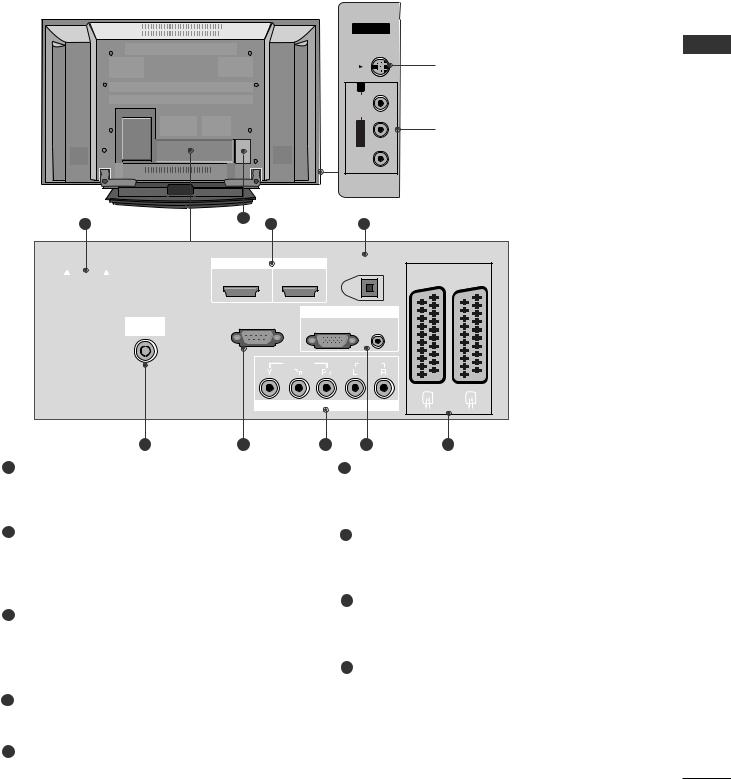
A This is a simplified representation of the back panel. Image shown may differ from your TV.
Plasma TV Models
|
|
|
AV IN 3 |
|
|
|
|
S-VIDEO |
|
|
|
|
|
S-Video Input |
|
|
|
R |
Connect S-Video out from an |
|
|
|
AUDIO |
S-VIDEO device. |
|
|
|
L/MONO |
Audio/Video Input |
|
|
|
|
|
|
|
|
VIDEO |
Connect audio/video output |
|
|
|
from an external device to |
|
|
|
|
|
these jacks. |
1 |
9 |
2 |
3 |
|
|
|
|||
|
EJECT |
|
|
|
|
HDMI/DVI IN |
HDMI IN |
DIGITAL AUDIO OUT |
|
|
|
|
1 |
2 |
(OPTICAL) |
AV 1 |
AV 2 |
|
PCMCIA |
|
|
||||
|
|
|
|
|
|
|
CARD SLOT |
|
|
|
|
|
|
|
RS-232C IN |
|
RGB IN |
|
|
|
ANTENNA |
(CONTROL & SERVICE) |
RGB(PC) |
AUDIO |
|
|
|
IN |
|
|
|
(RGB/DVI) |
|
|
|
|
|
|
|
|
|
|
|
VIDEO |
|
AUDIO |
|
|
|
|
COMPONENT IN |
|
|
|
|
4 |
5 |
|
6 |
7 |
|
8 |
1PCMCIA (Personal Computer Memory Card International Association) Card Slot
(This feature is not available in all countries.)
2HDMI Input
Connect a HDMI signal to HDMI IN.
Or DVI(VIDEO)signal to HDMI/DVI port with DVI to HDMI cable.
3DIGITAL AUDIO OUT (OPTICAL)
Connect digital audio from various types of equipment.
Note: In standby mode, these ports do not work.
4Antenna Input
Connect RF antenna (UHF) to this jack.
5RS-232C IN (CONTROL & SERVICE) PORT
Connect to the RS-232C port on a PC.
6Component Input
Connect a component video/audio device to these jacks.
7RGB/DVI Audio Input
Connect the monitor output from a PC to the appropriate input port.
8Euro Scart Socket (AV1/AV2)
Connect scart socket input or output from an external device to these jacks.
9Power Cord Socket
This TV operates on an AC power. The voltage is indicated on the Specifications page. Never attempt to operate the TV on DC power.
PREPARATION
7
PREPARATION
PREPARATION
|
|
32LT7* |
|
|
|
37LT7* |
|
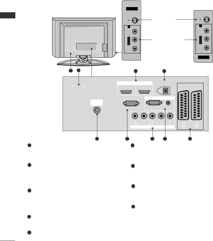
LCD TV Models |
|
|
|
|
|
|
42LT7* |
|
|
AV IN 3 |
|
|
|
|
|
|
|
S-VIDEO |
|
|
|
S-VIDEO |
|
|
|
|
|
|
|
||
|
|
|
|
S-Video Input |
|
|
|
|
|
R |
|
Connect S-Video out |
|
R |
|
|
|
AUDIO |
|
from an S-VIDEO device. |
AUDIO |
||
|
|
L/MONO |
|
Audio/Video Input |
L/MONO |
||
|
|
|
|
|
|||
|
|
VIDEO |
|
Connect audio/video |
|
VIDEO |
|
|
|
|
output from an external |
||||
|
|
|
|
device to these jacks. |
|
AV IN 3 |
|
9 |
1 |
|
2 |
|
3 |
|
|
|
EJECT |
|
|
|
|
|
|
|
|
HDMI/DVI IN |
HDMI IN |
DIGITAL AUDIO OUT |
|
|
|
|
|
1 |
2 |
|
(OPTICAL) |
AV 1 |
AV 2 |
|
PCMCIA |
|
|
||||
|
|
|
|
|
|
|
|
CARD SLOT |
|
|
|
|
|
|
|
|
|
RS-232C IN |
RGB IN |
|
|
||
|
ANTENNA |
|
|
|
|
||
|
|
|
|
|
|
|
|
|
IN |
|
|
|
AUDIO |
|
|
|
|
(CONTROL & SERVICE) |
RGB(PC) |
|
|
||
|
|
(RGB/DVI) |
|
|
|||
|
|
|
VIDEO |
|
AUDIO |
|
|
|
|
|
COMPONENT IN |
|
|
||
|
4 |
5 |
|
6 |
7 |
|
8 |
1PCMCIA (Personal Computer Memory Card International Association) Card Slot
(This feature is not available in all countries.)
2HDMI Input
Connect a HDMI signal to HDMI IN.
Or DVI(VIDEO)signal to HDMI/DVI port with DVI to HDMI cable.
3DIGITAL AUDIO OUT (OPTICAL)
Connect digital audio from various types of equipment.
Note: In standby mode, these ports do not work.
4Antenna Input
Connect RF antenna (UHF) to this jack.
5RS-232C IN (CONTROL & SERVICE) PORT
Connect to the RS-232C port on a PC.
6Component Input
Connect a component video/audio device to these jacks.
7RGB/DVI Audio Input
Connect the monitor output from a PC to the appropriate input port.
8Euro Scart Socket (AV1/AV2)
Connect scart socket input or output from an external device to these jacks.
9Power Cord Socket
This TV operates on an AC power. The voltage is indicated on the Specifications page. Never attempt to operate the TV on DC power.
8
STAND INSTALLATION (Only 32/37LT7* model)
1Carefully place the TV screen side down on a cushioned surface to protect the screen from damage.
2Assemble the TV as shown.
3 |
Fix the 4 bolts |
securely using the holes in the |
back of the TV. |
|
PREPARATION
ATTACHING THE TV TO A DESK (Only 32/37LT7* model)
The TV must be attached to desk so it cannot be pulled in a forward/backward direction, potentially causing injury or damaging the product. Use only an attached screw.
Stand |
1-Screw |
Desk
! WARNING
GTo prevent TV from falling over, the TV should be securely attached to the floor/wall per installation instructions. Tipping, shaking, or rocking the machine may cause injury.
9
PREPARATION
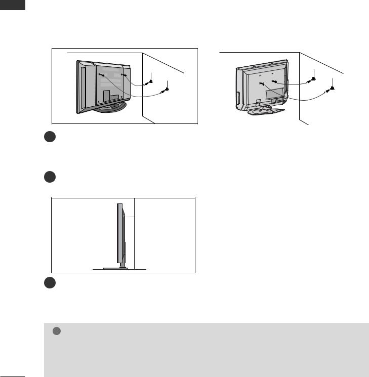
ATTACHING THE TV TO A WALL
(This feature is not available for all models.)
PREPARATION
■Position the TV close to the wall to avoid the possibility of it falling when pushed.
■The instructions shown below are a safer way to set up the TV, which is to fix it to the wall, avoiding the
possibility of it falling forwards if pulled. This will prevent the TV from falling forward and causing injury. This will also prevent the TV from damage. Ensure that children do not climb or hang from the TV.
|
1 |
1 |
|
2 |
2 |
|
|
or |
1 |
Use the eye-bolts or TV brackets/bolts to fix the TV to the wall as shown in the picture. |
|
(If your TV has bolts in the eyebolts, loosen then bolts.)
* Insert the eye-bolts or TV brackets/bolts and tighten them securely in the upper holes.
2Secure the wall brackets with bolts (must purchase seperately) to the wall. Ensure that both brackets are even.
3
3Use a strong cord (must purchase separately) to secure the TV.
Secure the cord in such a way that it becomes taught when the TV is in position.
!NOTE
GWhen moving the TV undo the cords first.
GUse a platform or cabinet string and large enough to support the size and weight of the TV.
GTo use the TV safely make sure that the height of the bracket on the wall and on the TV is the same.
10

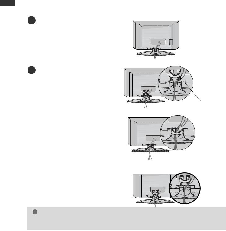
BACK COVER FOR WIRE ARRANGEMENT
Plasma TV models
1 Grip the CABLE MANAGEMENT and push the cover upwards.
PREPARATION |
CABLE MANAGEMENT
2Connect the cables as necessary.
To connect additional equipment, see the External equipment Setup section of the manual.
3 Reinstall the CABLE MANAGEMENT as shown.
11
PREPARATION
PREPARATION
LCD TV models
1Connect the cables as necessary.
To connect additional equipment, see the
External equipment Setup section.
2 Install the CABLE MANAGEMENT as shown.
CABLE MANAGEMENT
How to remove the cable management
Hold the CABLE MANAGEMENT with both hands and pull it upward.
! NOTE
GDo not use the CABLE MANAGEMENT to lift the TV.
-If the TV is dropped, you may be injured or the TV may be damaged.
12
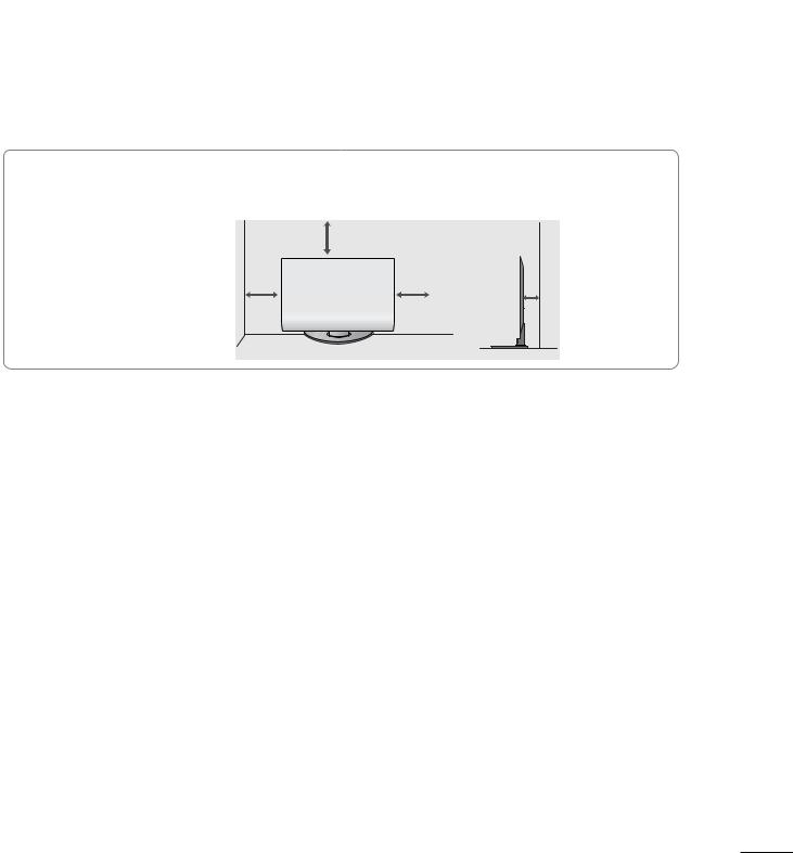
■The TV can be installed in various ways such as on a wall, or on a desktop etc.
■The TV is designed to be mounted horizontally.
EARTHING
Ensure that you connect the earth wire to prevent possible electric shock. If grounding methods are not possible, have a qualified electrician install a separate circuit breaker. Do not try to earth the TV by connecting it to telephone wires, lightening rods or gas pipes.
Power Supply
Circuit breaker
Desktop Pedestal Installation
For adequate ventilation allow a clearance of 4” (10cm) all around the TV .
4 inches
4 inches |
|
|
|
|
|
4 inches |
|
4 inches |
|
|
|
|
|
|
|||
|
|
|
|
|
|
|
|
|
|
|
|
|
|
|
|
|
|
|
|
|
|
|
|
|
|
|
|
|
|
|
|
|
|
|
|
|
|
|
|
|
|
|
|
|
Wall Mount: Horizontal installation
For adequate ventilation allow a clearance of 4” (10cm) all around the TV. We recommend that you use a wall mounting bracket of LG brand when mounting the TV to a wall.
 4 inches
4 inches
4 inches |
4 inches |
 4 inches
PREPARATION
13
PREPARATION
■ To prevent damage do not connect to the mains outlet until all connections are made between the devices.
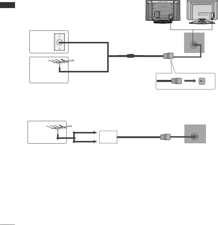
ANTENNA CONNECTION
■For optimum picture quality, adjust antenna direction.
■An antenna cable and converter are not supplied.
PREPARATION
Wall
Antenna
Socket
Outdoor
Antenna
(VHF, UHF)
Antenna
Multi-family Dwellings/Apartments
(Connect to wall antenna socket) ANTENNA
IN
RF Coaxial Wire (75 ohm)
Single-family Dwellings /Houses
(Connect to wall jack for outdoor antenna)
- 5V antenna power works In Digital mode only. (Refer to p. 40)
UHF
ANTENNA
IN
Signal Amplifier
VHF
■In poor signal areas, to achieve better picture quality it may be necessary to install a signal amplifier to the antenna as shown above.
■If signal needs to be split for two TVs,use an antenna signal splitter for connection.
14
EXTERNAL EQUIPMENT SETUP
■To avoid damaging any equipment, never plug in any power cords until you have finished connecting all equipment.
■This section on EXTERNAL EQUIPMENT SETUP mainly uses diagrams for the Plasma TV models.
HD RECEIVER SETUP
■This TV can receive Digital RF/Cable signals without an external digital set-top box. However, if you do receive Digital signals from a digital set-top box or other digital external device, refer to the diagram as shown below.
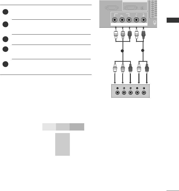
Connecting with a component cable |
|
|
|
|
|
|
VIDEO |
AUDIO |
|
1 |
Connect the video outputs (Y, PB, PR) of the digital set |
|
|
|
top box to the COMPONENT IN VIDEO jacks on the |
COMPONENT IN |
|
EXTERNAL |
|
|
|
|
||
|
TV. |
|
|
|
|
|
|
|
|
2 |
Connect the audio output of the digital set-top box to |
|
|
|
|
the COMPONENT IN AUDIO jacks on the TV. |
|
|
EQUIPMENT |
|
|
1 |
2 |
|
|
|
|
||
3 |
Turn on the digital set-top box. |
|
|
|
|
(Refer to the owner’s manual for the digital set-top box.) |
|
|
SETUP |
4 |
Select COMPONENT input source using the INPUT |
|
|
|
|
|
|
||
button on the remote control. |
|
|
|
|
|
|
|
|
|
Signal |
Component |
HDMI1/2 |
|
|
|
|
|
|
480i/576i |
Yes |
No |
480p/576p |
Yes |
Yes |
720p/1080i |
Yes |
Yes |
1080p |
No |
Yes |
|
|
|
15
EXTERNAL EQUIPMENT SETUP
SETUP EQUIPMENT EXTERNAL
Connecting a set-top box with an HDMI cable
|
|
|
|
|
HDMI/DVI IN |
HDMI IN |
DIGITAL AUDIO OUT |
|
|
|
|
|
|
|
1 |
2 |
|
(OPTICAL) |
AV |
|
|
|
|
|
|
|
|||
1 |
Connect the digital set-top box to HDMI/DVI IN |
or |
|
|
RGB IN |
|
|||
HDMI IN jack on the TV. |
|
|
|
RS-232C IN |
|
|
|||
|
|
|
A |
& SERVICE) |
RGB(PC) |
AUDIO |
|
||
|
|
|
|
|
|
|
|
(RGB/DVI) |
|
2 |
Turn on the digital set-top box. |
|
|
|
VIDEO |
|
AUDIO |
|
|
|
|
|
|
|
|
|
|||
|
(Refer to the owner’s manual for the digital set-top box.) |
|
COMPONENT IN |
|
|||||
|
|
|
|
|
1 |
|
|||
|
|
|
|
|
|
|
|
|
|
3 |
Select HDMI1 or HDMI2 |
input source |
using |
the |
|
|
|
|
|
INPUT button on the remote control. |
|
|
|
|
|
|
|
||
|
|
|
|
|
|
|
|
||
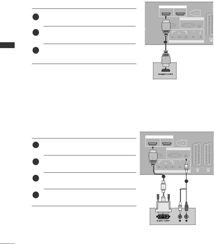
Connecting with a HDMI to DVI cable
|
|
HDMI/DVI IN |
HDMI IN |
DIGITAL AUDIO OUT |
|
|
|
|
|
1 |
2 |
|
(OPTICAL) |
AV 1 |
AV 2 |
|
|
|
|
||||
1 |
Connect the digital set-top box to HDMI/DVI IN jack |
|
|
|
|
|
|
|
on the TV. |
RS-232C IN |
|
RGB IN |
|
|
|
|
|
|
AUDIO |
|
|
||
|
|
(CONTROL & SERVICE) |
RGB(PC) |
|
|
||
|
|
|
|
|
(RGB/DVI) |
|
|
2 |
Connect the audio output of the digital set-top box to |
|
VIDEO |
|
AUDIO |
|
|
|
|
|
|
|
|
||
|
the AUDIO IN (RGB/DVI) jack on the TV. |
|
|
|
|
|
|
|
|
|
COMPONENT IN |
|
|
||
3 |
Turn on the digital set-top box. (Refer to the owner’s |
|
1 |
|
|
|
|
|
|
|
2 |
|
|
||
|
manual for the digital set-top box.) |
|
|
|
|
|
|
|
|
|
|
|
|
|
|
4 |
Select HDMI1 input source using the INPUT button |
|
|
|
|
|
|
|
on the remote control. |
|
|
|
|
|
|
16
DVD SETUP |
|
|
|
|
|
|
Connecting with a component cable |
|
|
|
|
|
|
|
|
|
RS-232C IN |
RGB IN |
|
|
|
|
|
(CONTROL & SERVICE) |
RGB(PC) |
AUDIO |
|
|
|
|
|
|
(RGB/DVI) |
|
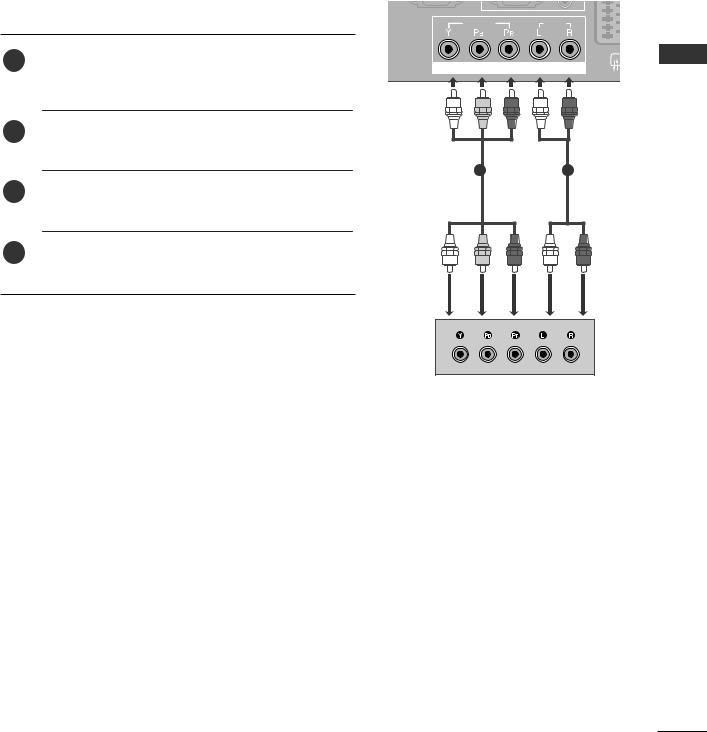
1 |
Connect the video outputs (Y, PB, PR) of the DVD to the |
|
|
|
|
|
COMPONENT IN VIDEO jacks on the TV. |
|
VIDEO |
|
AUDIO |
|
|
|
|
|
|
|||
2 |
Connect the audio outputs of the DVD to the |
|
COMPONENT IN |
|
EXTERNAL |
|
|
|
|
|
|||
|
COMPONENT IN AUDIO jacks on the TV. |
|
|
|
|
|
|
|
|
|
|
|
|
3 |
Turn on the DVD player, insert a DVD. |
|
|
|
|
EQUIPMENT |
5 |
Refer to the DVD player's manual for operating |
|
|
|
|
|
4 |
Select COMPONENT input source using the |
INPUT |
1 |
|
2 |
|
|
button on the remote control. |
|
|
|
|
|
|
instructions. |
|
|
|
|
SETUP |
|
|
|
|
|
|
|
Component Input ports
To achieve better picture quality, connect a DVD player to the component input ports as shown below.
Component ports on the TV |
Y |
PB |
PR |
|
|
|
|
|
|
|
|
|
Y |
PB |
PR |
Video output ports |
Y |
B-Y |
R-Y |
on DVD player |
Y |
Cb |
Cr |
|
Y |
Pb |
Pr |
|
|
|
|
17
EXTERNAL EQUIPMENT SETUP
SETUP EQUIPMENT EXTERNAL
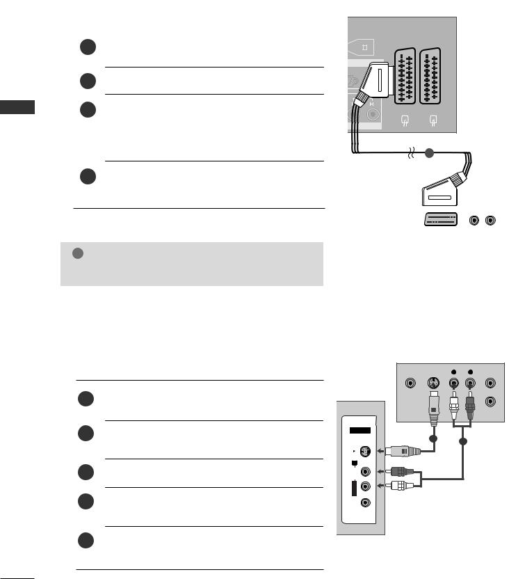
Connecting with a Euro Scart cable
|
|
GITAL AUDIO OUT |
|
|
|
|
|
|
|
|
|
|
||||
|
Connect the Euro scart socket of the DVD to the AV1 |
(OPTICAL) |
AV 1 AV 2 |
|||||||||||||
|
|
|
|
|
|
|||||||||||
1 |
|
|
|
|
|
|
|
|
|
|
|
|
|
|
|
|
Euro scart socket on the TV. |
|
|
|
|
|
|
|
|
|
|
|
|
|
|
|
|
|
|
|
|
|
|
|
|
|
|
|
|
|
|
|
|
|
GB |
C)
2 Turn on the DVD player, insert a DVD.
3Select AV1 input source using the INPUT button on
the remote control.
N
If connected to AV2 Euro scart socket, select AV2
input source.
1
4 Refer to the DVD player's manual for operating instructions.
|
|
(R) AUDIO (L) |
|
|
|
|
|
|
|
|
|
|
AUDIO/ |
|
|
VIDEO |
|
|
|
|
! NOTE
G Any Euro scart cable used must be signal protected.
Connecting with a S-Video cable
Connect the S-VIDEO output of the DVD to the S -
1VIDEO input on the TV.
2Connect the audio outputs of the DVD to the AUDIO input jacks on the TV.
3Turn on the DVD player, insert a DVD.
4Select AV3 input source using the INPUT button on the remote control.
5Refer to the DVD player's manual for operating instructions.
VIDEO |
S-VIDEO |
L |
R |
ANT IN |
|
|
|
|
ANT OUT |
AV IN 3 |
|
|
|
|
S-VIDEO |
1 |
|
2 |
|
|
|
|
||
R |
|
|
|
|
AUDIO |
|
|
|
|
L/MONO |
|
|
|
|
VIDEO |
|
|
|
|
18
Connecting the HDMI cable
|
1 |
Connect the HDMI output of the DVD to the HDMI/DVI |
|
|
|
|
|
|
IN or HDMI IN jack on the TV. |
|
|
|
|
|
|
HDMI/DVI IN |
HDMI IN |
DIGITAL AUDIO OUT |
|
|
|
|
1 |
2 |
(OPTICAL) |
|
|
|
2 |
|
|
|
||
|
Select HDMI1or HDMI2 input source using the |
|
|
|
|
|
|
|
INPUT button on the remote control. |
|
RGB IN |
|
|
|
|
232C IN |
|
|
||
|
|
SERVICE) |
RGB(PC) |
AUDIO |
|
|
|
|
|
|
|
(RGB/DVI) |
EXTERNAL |
|
3 |
Refer to the DVD player's manual for operating |
VIDEO |
|
AUDIO |
|
|
|
|
||||
|
|
instructions. |
|
|
||
|
|
|
|
|
|
|
|
|
|
COMPONENT IN |
|
EQUIPMENT |
|
|
|
1 |
|
|
|
|
|
|
|
|
|
|
|
! |
NOTE |
|
|
|
SETUP |
|
G The TV can receive video and audio signals simultaneously |
|
|
|
|||
|
|
|
|
|||
|
when using a HDMI cable. |
|
|
|
|
|
G If the DVD player does not support Auto HDMI, you must |
|
|
|
|
||
|
TV the output resolution appropriately. |
|
|
|
|
|
INSERTION OF CI MODULE
-To view the scrambled (pay) services in digital TV mode.
-This feature is not available in all countries.
Insert the CI Module to PCMCIA (Personal Computer
1Memory Card International Association) CARD SLOT of TV as shown.
For further information, see p.43.
|
|
HDMI |
PCMCIA |
|
|
CARD SLOT |
|
|
1 |
ANTENNA |
(CONT |
|
IN |
|
TV
19
EXTERNAL EQUIPMENT SETUP
SETUP EQUIPMENT EXTERNAL
VCR SETUP
■To avoid picture noise (interference), allow adequate distance between the VCR and TV.
■If 4:3 picture format is used for an extended period the fixed images on the sides of the screen may remain visible. (Only Plasma TV models)
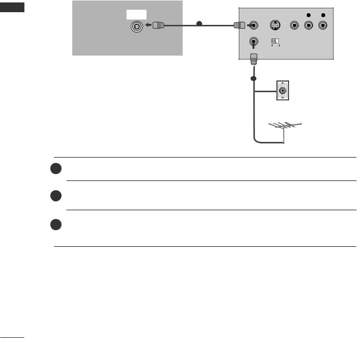
Connecting with a RF cable
RS-232C IN
(CONTROL & SERVICE)
ANTENNA |
ANT OUT |
S-VIDEO VIDEO |
L |
R |
|
IN |
|||||
|
|
|
|
1 VIDEO
OUTPUT
SWITCH
Wall Jack
2
Antenna
1
2
Connect the ANT OUT socket of the VCR to the ANTENNA IN socket on the TV.
Connect the antenna cable to the ANT IN socket of the VCR.
3Press the PLAY button on the VCR and match the appropriate programme between the TV and VCR for viewing.
20
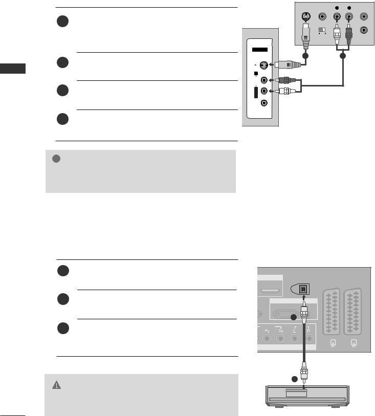
Connecting with a Euro Scart |
|
|
|
|
DIGITAL AUDIO OUT |
|
|
|
(OPTICAL) |
AV 1 |
AV 2 |
|
Connect the Euro scart socket of the VCR to the AV1 |
||
1 |
|
|
|
Euro scart socket on the TV. |
|
|
|
|
|
|
|
|
RGB |
|
|
|
GB(PC) |
|
|
2 |
Insert a video tape into the VCR and press PLAY on |
|
|
the VCR. (Refer to the VCR owner’s manual.) |
|
3 |
Select AV1 input source using the INPUT button on |
ENT IN |
the remote control. |
|
|
|
|
1
4If connected to AV2 Euro scart socket, select AV2
input source.
|
|
(R) AUDIO (L) |
|
|
|
|
|
|
|
|
|
|
AUDIO/ |
|
|
VIDEO |
|
|
|
|
! NOTE
G Any Euro Scart cable used must be signal shielded.
SETUP EQUIPMENT EXTERNAL
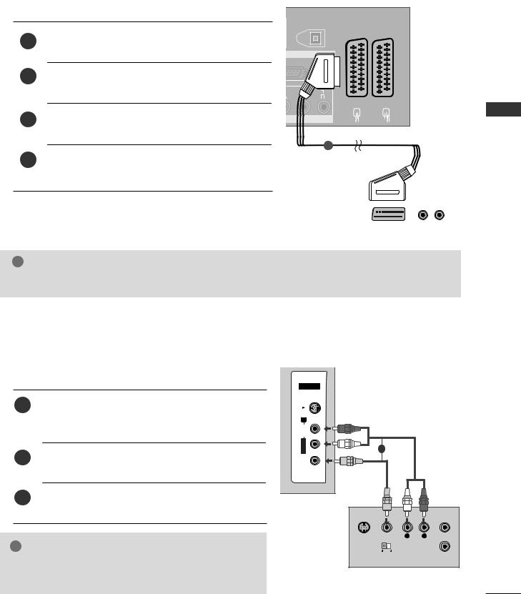
Connecting with an RCA cable |
|
|
|
|
|
||
|
|
|
AV IN 3 |
|
|
|
|
|
1 |
Connect the AUDIO/VIDEO jacks between TV and |
S-VIDEO |
|
|
|
|
|
|
|
|
|
|
||
|
|
VCR. Match the jack colours (Video = yellow, Audio Left |
R |
|
|
|
|
|
|
= white, and Audio Right = red) |
AUDIO |
|
|
|
|
|
|
|
|
|
|
|
|
|
2 |
Insert a video tape into the VCR and press PLAY on |
L/MONO |
1 |
|
|
|
|
VIDEO |
|
|
|
|
||
|
|
the VCR. (Refer to the VCR owner’s manual.) |
|
|
|
|
|
|
|
|
|
|
|
|
|
|
3 |
Select AV3 input source using the INPUT button on |
|
|
|
|
|
|
|
the remote control. |
|
|
|
|
|
|
|
|
S-VIDEO |
VIDEO |
L |
R |
ANT IN |
! |
NOTE |
|
OUTPUT |
|
|
ANT OUT |
|
|
|
|
|
|
|
||
|
|
|
|
SWITCH |
|
|
|
G If you have a mono VCR, connect the audio cable from the |
|
|
|
|
|
||
|
VCR to the AUDIO L/MONO jack of the TV. |
|
|
|
|
|
|
21
EXTERNAL EQUIPMENT SETUP
SETUP EQUIPMENT EXTERNAL
Connecting with a S-Video cable |
|
|
|
|
|
|
||
|
|
|
|
S-VIDEO |
VIDEO |
L |
R |
ANT IN |
|
1 |
Connect the S-VIDEO output of the VCR to the S - |
|
|
|
|
|
|
|
VIDEO input on the TV. The picture quality is |
|
|
|
|
|
|
|
|
|
|
|
|
|
|
|
|
|
|
improved; compared to normal composite (RCA cable) |
|
|
OUTPUT |
|
|
ANT OUT |
|
|
input. |
|
|
SWITCH |
|
|
|
|
|
|
|
|
|
|
|
|
|
|
|
AV IN 3 |
|
|
|
|
|
|
2 |
Connect the audio outputs of the VCR to the AUDIO |
S-VIDEO |
1 |
|
|
2 |
|
|
|
|
|
|
|
|||
|
|
|
|
|
|
|
||
|
|
input jacks on the TV. |
R |
|
|
|
|
|
|
3 |
|
AUDIO |
|
|
|
|
|
|
Insert a video tape into the VCR and press PLAY on the |
L/MONO |
|
|
|
|
|
|
|
|
VCR. (Refer to the VCR owner’s manual.) |
|
|
|
|
|
|
|
|
VIDEO |
|
|
|
|
|
|
|
|
|
|
|
|
|
|
|
|
4 |
Select AV3 input source using the INPUT button on the |
|
|
|
|
|
|
|
|
remote control. |
|
|
|
|
|
|
! |
NOTE |
|
|
|
|
|
|
|
GIf both S-VIDEO and VIDEO sockets have been connected to the S-VHS VCR simultaneously, only the S-VIDEO can be received.
DIGITAL AUDIO OUT SETUP
Sending the TV’s audio signal to external audio equipment via the Digital Audio Output (Optical) port.
1 |
Connect one end of an optical cable to the TV Digital |
HDMI IN |
(OPTICAL) |
|
|
|
Audio (Optical) Output port. |
|
|
||
|
|
|
DIGITAL AUDIO OUT |
|
|
|
|
2 |
|
AV 1 |
AV 2 |
|
|
|
|
|
|
2 |
Connect the other end of the optical cable to the digi- |
|
RGB |
|
|
|
tal audio (optical) input on the audio equipment. |
RVICE) |
RGB(PC) |
|
|
|
|
|
|
||
3 |
Set the “TV Speaker option - Off” in the AUDIO menu. |
|
1 |
|
|
VIDEO |
|
|
|
||
|
|
|
|
|
|
|
(Gp.88). Refer to the external audio equipment |
|
|
|
|
|
instruction manual for operation. |
COMPONENT IN |
|
|
|
CAUTION |
|
2 |
|
|
|
|
|
|
|
||
GDo not look into the optical output port. Looking at the |
|
|
|
|
|
laser beam may damage your vision. |
|
|
|
|
|
22
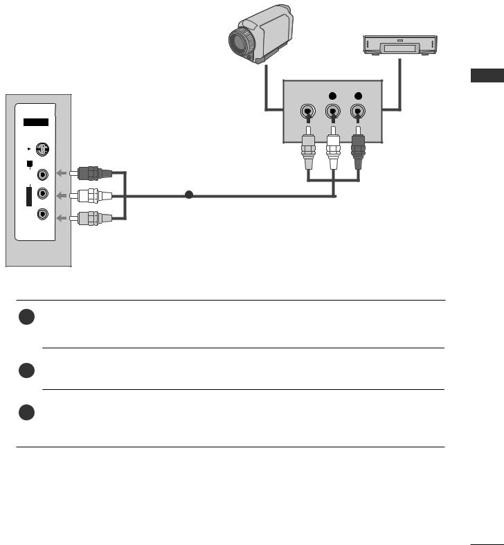
OTHER A/V SOURCE SETUP
Camcorder |
|
|
|
|
|
|
Video Game Set |
VIDEO |
L |
R |
EXTERNAL |
AV IN 3 |
|
|
|
S-VIDEO |
|
|
|
|
|
EQUIPMENT |
|
1 |
|
|
|
L/MONOAUDIOR |
|
|
|
VIDEO |
|
|
SETUP |
1Connect the AUDIO/VIDEO jacks between TV and external equipment. Match the jack colours. (Video = yellow, Audio Left = white, and Audio Right = red)
2Select AV3 input source using the INPUT button on the remote control.
3Operate the corresponding external equipment. Refer to external equipment operating guide.
23
EXTERNAL EQUIPMENT SETUP
SETUP EQUIPMENT EXTERNAL
PC SETUP
This TV provides Plug and Play capability, meaning that the PC adjusts automatically to the TV's settings.
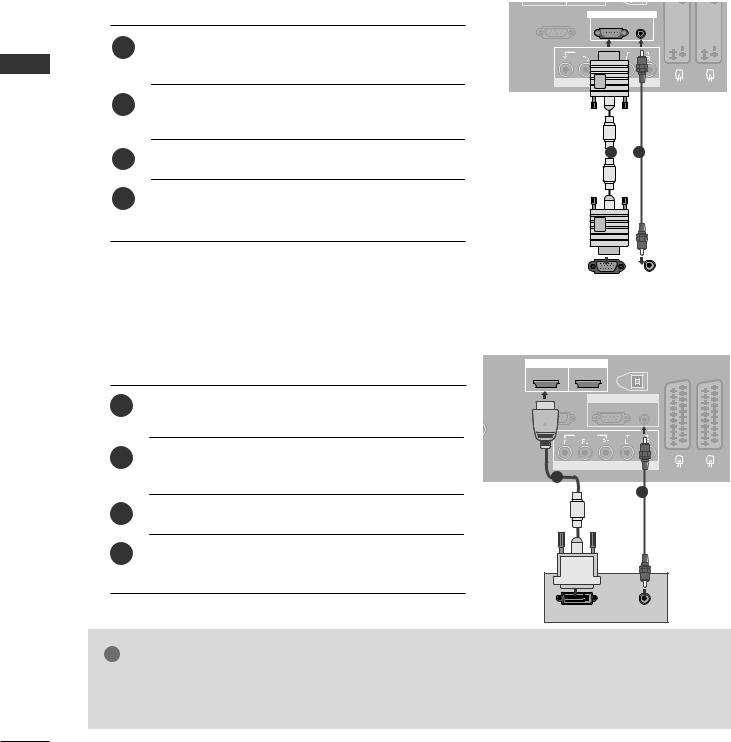
Connecting with a D-sub 15 pin cable
1Connect the RGB output of the PC to the RGB (P C) jack on the TV.
2Connect the PC audio output to the AUDIO IN (RGB/DVI) jack on the TV.
3Turn on the PC and the TV.
4Select RGB input source using the INPUT button on the remote control.
RS-232C IN |
|
|
|
|
|
|
|
|
|
|
RGB IN |
|
|
|
|
|
|
|
|||
(CONTROL & SERVICE) |
RGB(PC) |
AUDIO |
|
|
|
|
|
|
|
|
|
(RGB/DVI) |
|
|
|
|
|
|
|
||
VIDEO
1 2
|
|
|
|
RGB OUTPUT |
AUDIO |
||
|
|
|
|
|
|
|
|
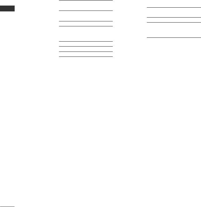
Connecting with a HDMI to DVI cable
|
|
HDMI/DVI IN HDMI IN |
DIGITAL AUDIO OUT |
|
||
|
|
1 |
2 |
(OPTICAL) |
AV 1 AV 2 |
|
|
|
|
|
|||
1 |
Connect the DVI output of the PC to the HDMI/DVI |
RS-232C IN |
RGB IN |
|
||
|
|
|||||
|
A |
& SERVICE) |
RGB(PC) |
AUDIO |
|
|
|
IN jack on the TV. |
|
|
|
(RGB/DVI) |
|
|
|
|
|
|
|
|
|
|
|
VIDEO |
|
AUDIO |
|
2 Connect the PC audio output to the AUDIO IN |
|
COMPONENT IN |
|
|
||
|
(RGB/DVI) jack on the TV. |
|
1 |
|
|
|
|
|
|
|
|
2 |
|
3Turn on the PC and the TV.
4 Select HDMI1 input source using the INPUT button on the remote control.
DVI-PC OUTPUT |
AUDIO |
! NOTE
G If the PC has a DVI output and no HDMI output, a separated audio connection is necessary.
G If the PC does not support Auto DVI, you need to set the output resolution appropriately.
24

! NOTE
G To enjoy vivid picture and sound, connect the PC to the TV.
G Avoid keeping a fixed image on the TV ’s screen for prolonged periods of time.The fixed image may become permanently imprinted on the screen;use a screen saver when possible.
G Connect the PC to the RGB (PC) or HDMI IN (or HDMI/DVI IN) port of the TV; change the resolution output of PC accordingly.
G There may be interference relating to resolution, vertical pattern, contrast or brightness in PC mode. Change the PC mode to another resolution or change the refresh rate to another rate or adjust the brightness and contrast on the menu until the picture is clear. If the refresh rate of the PC graphic card can not be changed, change the PC graphic card or consult the manufacturer of the PC graphic card.
G RGB input only supports the separate horizontal and vertical synchronization pulses in separate channels.
G We recommend using 1360x768, 60Hz (LCD TV models / 50PT8* models) / 1024x768, 60Hz (42PT8* models) for the PC mode, these should provide the best picture quality.
G Connect the signal cable from the monitor output port of the PC to the RGB (PC/DTV) port of the TV or the signal cable from the HDMI output port of the PC to the HDMI IN (or HDMI/DVI IN) port on the TV.
G Connect the audio cable from the PC to the Audio
input on the TV. (Audio cables are not included with the TV).
G If using a sound card, adjust PC sound as required. G This TV uses a VESA Plug and Play Solution. The TV provides EDID data to the PC system with a DDC protocol. The PC adjusts automatically when
using this TV.
G DDC protocol is preset for RGB (Analogue RGB), HDMI (Digital RGB) mode.
G If required, adjust the settings for Plug and Play functionality.
G If the graphic card on the PC does not output analogue and digital RGB simultaneously, connect only one of either RGB or HDMI IN (or HDMI/DVI IN) to display the PC output on the TV.
G If the graphic card on the PC does output analogue and digital RGB simultaneously, switch the TV to either RGB or HDMI; (the other mode is set to Plug and Play automatically by the TV.)
G DOS mode may not work depending on the video card if you use a HDMI to DVI cable.
G If you use too long an RGB-PC cable, there may be interference on the screen. We recommend using under 5m of cable. This provides the best picture quality.
SETUP EQUIPMENT EXTERNAL
25
EXTERNAL EQUIPMENT SETUP
SETUP EQUIPMENT EXTERNAL
Supported Display Resolution
RGB[PC] / HDMI[PC] mode |
|
|
HDMI[DTV] mode |
|||
|
|
|
|
|
|
|
Resolution |
Horizontal |
Vertical |
|
Resolution |
Horizontal |
Vertical |
Frequency(KHz) |
Frequency(Hz) |
|
Frequency(KHz) |
Frequency(Hz) |
||
|
|
|||||
720x400 |
31.468 |
70.08 |
|
|
31.469 |
59.94 |
|
640x480 |
|||||
|
31.469 |
|
|
|||
640x480 |
59.94 |
|
31.469 |
60.00 |
||
|
|
|||||
37.684 |
75.00 |
|
|
|||
|
|
720x480 |
31.47 |
59.94 |
||
|
37.879 |
|
|
|||
800x600 |
60.31 |
|
31.50 |
60.00 |
||
|
|
|||||
46.875 |
75.00 |
|
|
|||
|
|
720x576 |
31.25 |
50.00 |
||
832x624 |
49.725 |
|
|
|||
74.55 |
|
|
37.50 |
50.00 |
||
|
48.363 |
|
|
|
||
|
60.00 |
|
1280x720 |
44.96 |
59.94 |
|
1024x768 |
56.476 |
|
|
|||
70.00 |
|
|
45.00 |
60.00 |
||
|
60.123 |
|
|
|
||
|
75.029 |
|
|
33.72 |
59.94 |
|
1280x768 |
47.78 |
|
|
|
||
59.87 |
|
|
33.75 |
60.00 |
||
1360x768 |
47.72 |
|
|
|
||
59.8 |
|
|
28.125 |
50.00 |
||
1366x768 |
47.56 |
|
|
|
||
59.6 |
|
1920x1080 |
27.00 |
24.00 |
||
1920x1080 |
66.647 |
59.988 |
|
|||
|
|
56.25 |
50.00 |
|||
|
|
|
|
|
||
|
|
|
|
|
67.433 |
59.94 |
|
|
|
|
|
67.500 |
60.00 |
|
|
|
|
|
|
|
26
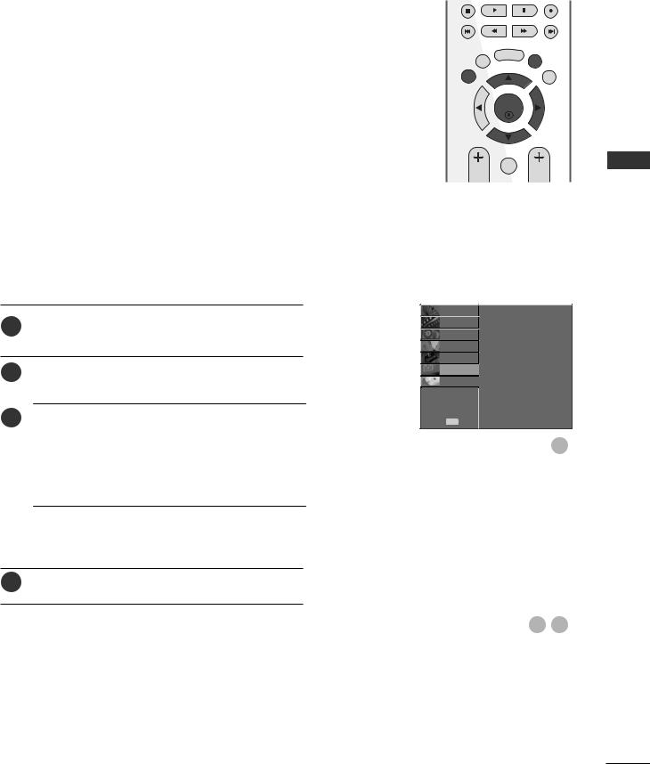
Screen Setup for PC mode
Auto Configure (RGB [PC] mode only)
Automatically adjusts picture position and minimizes image instability.
After adjustment, if the image is still not correct, your TV is functioning properly but needs further adjustment.
Auto configure
This function is for automatic adjustment of the screen position, clock, and phase. The displayed image will be unstable for a few seconds while the auto configuration is in progress.
1Press the MENU button and then use D or E button to select the SCREEN menu.
2Press the G button and then use D or E button to select Auto Config..
3Press the G button to start Auto Config..
•When Auto Config. has finished, OK will be shown on screen.
•If the position of the image is still not correct, try Auto adjustment again.
•If picture needs to be adjusted again after Auto adjustment in RGB (PC), you can adjust the
Manual Config..
4Press the EXIT button to return to normal TV viewing.
BACK |
DVR |
MENU |
|
|
|
EXIT |
|
GUIDE |
TIME |
OK |
TIME |
SHIFT |
|
SHIFT |
|
MARK |
|
|
FAV |
|
VOL |
|
PR |
SETUPO Auto Config.
PICTUREO Manual Config.
AUDIOO XGA Mode
Aspect Ratio
TIMEO Reset
OPTIONO
SCREEN G
D V RO

 Move MENU Prev.
1
|
|
To Set |
Auto Config. |
G |
|
Manual Config. |
|
|
XGA Mode |
|
|
Aspect Ratio |
|
|
Reset |
|
|
|
|
|
2 3
SETUP EQUIPMENT EXTERNAL
27
EXTERNAL EQUIPMENT SETUP
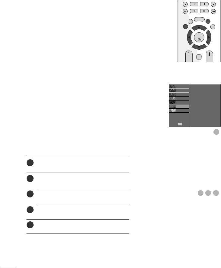
Adjustment for screen Phase, Clock, Position
If the picture is not clear after auto adjustment and especially if characters are still trembling, adjust the picture phase manually.
|
To correct the screen size, adjust Clock. |
|
EXTERNAL |
This function works in the following mode : RGB[PC]. |
|
|
||
|
Clock This function is to minimize any vertical bars or stripes |
|
SETUPEQUIPMENT |
visible on the screen background the horizontal |
|
screen size will also change. |
||
|
||
|
Phase This function allows you to remove any horizontal |
|
|
noise and clear or sharpen the image of characters. |
1Press the MENU button and then use D or E button to select the SCREEN menu.
2Press the G button and then D or E button to select
Manual Config..
3Press the G button and then D or E button to select
Phase, Clock, H-Position or V-Position.
4Press the F or G button to make appropriate adjustments.
5Press the EXIT button to return to normal TV viewing.
BACK |
DVR |
MENU |
|
|
|
EXIT |
|
GUIDE |
TIME |
OK |
TIME |
SHIFT |
|
SHIFT |
|
MARK |
|
|
FAV |
|
VOL |
|
PR |
SETUPO Auto Config.
PICTUREO Manual Config.
AUDIOO XGA Mode
Aspect Ratio
TIMEO Reset
OPTIONO
SCREEN G
D V RO

 Move MENU Prev.
1
Auto Config. |
|
|
|
|
Manual Config. |
G |
Phase |
0 |
|
XGA Mode |
|
Clock |
0 |
|
Aspect Ratio |
|
H-Position |
0 |
|
Reset |
|
V-Position |
0 |
|
|
|
|
|
|
2 3 4
28
 Loading...