

Page 1

LS430 UCF30
Safety Recall – Fuel Pump Replacement
Investigations by Toyota Motor Corporation have determined a requirement exists for the initiation of a
safety recall campaign, to be conducted in accordance with the FCAI Code of Practice for safety related
recalls, affecting a range of Lexus LS430 vehicles.
DESCRIPTION OF PROBLEM
In the subject vehicles, the fuel pump impeller may have been moulded in such a way that it can be
deformed by alcohol contained in the fuel, causing the impeller to contact the fuel pump body. This
condition could increase the rotation resistance of the impeller and, in the worst case, may result in
failure of the fuel pump.
INVOLVED VEHICLES
Lexus LS430 vehicles produced from 29th July 2003 to 9th March 2004 are being recalled, refer VIN
range listed below.
A total of 179 vehicles are involved.
VEHICLE IDENTIFICATION
Model Name Model Code VDS VIS Production Period
LS430 UCF30 BN36F# 00123382 – 00155462
NOTE:
(1) Not all vehicles within the above range were sold in Australia.
(2) # = Check digit – alpha or numeric.
29 July 2003 to
9 March 2004
TIMING / OWNER NOTIFICATION
Lexus has contacted owners of the involved vehicles by telephone and letter advising them of the need
for this campaign. The mail out occurred on 11th February 2005.
1
© Toyota Motor Corporation Australia Limited Date: Feb 2006
A.B.N. 64 009 686 097 Section: Fuel
Reproduction in whole or part prohibited without written approval. No: 01
Page 2

DEALER ACTION
Dealers are required to:
1. Confirm vehicle is within involved VIN range.
2. Replace the fuel pump as per the Technical Instructions included in this Bulletin.
3. Apply the Campaign Identification Label and Submit a warranty claim.
CORRECTION PARTS REQUIRED TO COMPLETE THIS CAMPAIGN
Replacement parts are packaged together in kit form and are available through normal parts channels.
Parts information is as follows.
Part Number Part Name Quantity per Vehicle
04004 – 18150 Pump Kit, Fuel 1
TECHNICAL INSTRUCTIONS
Refer to the Technical Instructions included in this Bulletin for details of the fuel pump replacement
procedures.
CAMPAIGN IDENTIFICATION LABEL
Fill in the Campaign Identification Label and affix it to the right hand side ‘A’ pillar post between the
upper and lower door hinges. The diagram below shows the type of label and completion method.
This label is designed so the completion information can be impressed into the label rather than being
marked with ink, therefore the following applies:
1. Prior to affixing label, using a ballpoint pen, impress the date and campaign code number (4520M)
and dealer code onto the label.
2. Ensure the right hand ‘A’ pillar post between the upper and lower door hinges is free of grease and
oil in the area where the label is to be affixed.
3. Peel label from backing and affix to the ‘A’ pillar.
2
© Toyota Motor Corporation Australia Limited Date: Feb 2006
A.B.N. 64 009 686 097 Section: Fuel
Reproduction in whole or part prohibited without written approval. No: 01
Page 3

TECHNICAL INSTRUCTIONS
FUEL PUMP REPLACEMENT ON LS430
Page
1. OPERATION FLOW CHART
2. AFFECTED VEHICLES
3. PREPARATION
4. WORK PROCEDURE
−−−−−−−−−−−−−−−−−−−−−−−−−−−
−−−−−−−−−−−−−−−−−−−−−
−−−−−−−−−−−−−−−−−−−−−−
−−−−−−−−−−−−−−−−−
2
2
2
3
1
Page 4

1. OPERATION FLOW CHART
Check whether or not the vehicle has the
affected vehicle frame number.
Yes
Replace the fuel pump
Finish
2. AFFECTED VEHICLES
Frame No. list:
No
No further action required.
WMI VDS Frame No.
JTH BN36F# 00123382 to 00155462
A
B
3. PREPARATION
Necessary Parts:
Part No. Part Name Q’ty/Vehicle
04004−18150
(23239−21010)
(23221−50110)
(77169−33020)
(23217−74021)
(23229−16010)
B74205
Fuel Pump Kit
1. VEHICLE IDENTIFICATION NUMBER
The vehicle identification number is stamped on the outer surface of the front right side frame. This number is also stamped
on the manufacturer’s plate and certification regulation plate,
as shown in the illustration.
A: Vehicle Identification Number Plate
B: Certification Label
1
(Fuel Pump Filter Seal)
(Fuel Pump Assy)
(Fuel Suction Tube Set Gasket)
(Fuel Pump Filter)
(Clip for Fuel Pump Filter)
(1)
(1)
(1)
(1)
(1)
Tools:
Name Part No.
Standard tools −
2
Page 5

4. WORK PROCEDURE
COMPONENTS
Rear Seat Cushion Assy (Fixed Type)
Rear Floor Service Hole Cover No. 2
Fuel Pump & Sender Gauge Connector
6.0 (61, 52 in.·lbf)
Rear Seat Cushion Assy (Power Adjust Type)
Fuel Tank Main Tube Sub−assy
x8
Fuel Tank Vent Tube Set Plate
N·m (kgf·cm, ft·lbf)
# Non−reusable part
Tube Joint Clip
Fuel Pump and
Sender Gauge Assy
# Gasket
Fuel Sub−suction Hose
: Specified torque
A93909
3
Page 6

# Fuel Pump Filter Seal
Fuel Suction Plate
with Sender Gauge
Fuel Suction Plate
Fuel Filter Assy
Fuel Pump
Connector
Spacer
Fuel Pump Assembly
Fuel Pump Cushion Rubber
Fuel Suction Support No. 2
# Non−reusable part
G37988
4
Page 7

REPLACEMENT
Hook
Removal
CAUTION:
Do not smoke or work near an open flame when working on
the fuel pump.
1.
RECORD RADIO STATION PRESETS AND CUSTOMER
STATION SETTINGS
2.
DISCONNECT BATTERY NEGATIVE TERMINAL
DRAIN FUEL
3.
NOTICE:
These procedures should be performed with the fuel tank
less than 1/4 full.
SEPARATED TYPE REAR SEAT:
4.
REMOVE SEPARATE TYPE REAR SEAT CUSHION
ASSY LH
(a) Pull up the 2 front portions of the seat cushion, then re-
move it.
(b) w/ Seat heater or climate control seat system:
Disconnect the connector.
Hook
B75246
B75248
FIXED TYPE REAR SEAT:
5.
REMOVE BENCH TYPE REAR SEAT CUSHION ASSY
(a) w/ Seat heater:
Disconnect the connector.
(b)
Pull up the front portion of the seat and remove.
NOTICE:
The cushion frame deforms easily. To avoid deforming the
seat cushion, place your hands near the hook and on both
sides of the hook, and then pull up on the seat cushion. Do
the same for all the hooks.
6. REMOVE REAR FLOOR SERVICE HOLE COVER NO.
(a) Remove the 3 cap nuts and service hole cover.
2
A89509
5
Page 8

Fuel
Pump
Connector
Pull
A89497
. WORK FOR PREVENTING FUEL FROM SPILLING
7
OUT
(a) Disconnect the fuel pump connector.
(b) Start the engine. After the engine has stopped on its own,
turn the ignition switch OFF.
HINT:
There is a possibility that DTC P0171 and/or P0174 system
too lean is output.
(c) Disconnect the negative (−) terminal cable from the bat-
tery.
(d) Check that the engine does not start.
(e) Remove the fuel tank cap, and let the air out of the fuel
tank
8.
REMOVE FUEL TANK MAIN TUBE SUB−ASSY
NOTICE:
Check for dirt contamination in the pipe and around
-
the connector. Clean if necessary. Foreign matter
may damage the O−ring or cause leaks in the seal between the pipe and connector.
Do not use any tools in these procedures.
-
Do not forcefully bend or twist the nylon tube.
-
Check for dirt contamination on the pipe seal surface.
-
Clean if necessary.
Put the pipe and connector ends in vinyl bags to pre-
-
vent damage and dirt contamination.
If the pipe and connector are stuck together, pinch the
-
tube between your fingers and turn it carefully to free
it. Then disconnect the tube.
(a) Remove the tube joint clip.
(b) Pull out the fuel main tube.
(c) Plug the port of the fuel suction plate with a clean rubber
cap.
Remove
Plug
A54096
9. REMOVE FUEL TANK VENT TUBE SET PLATE
(a) Remove the 8 bolts and set plate.
G37984
6
Page 9

Fuel Sub−suction Hose
Pry
Pry
A54098
A89518
.
10
REMOVE FUEL PUMP AND SENDER GAUGE
ASSEMBLY
(a) Lift up the fuel pump and sender gauge. Disconnect the
fuel sub−suction hose from the fuel return jet tube and remove the fuel pump, sender gauge and gasket.
CAUTION:
Do not damage the fuel pump filter.
-
Be careful not to bend the arm of the sender gauge.
-
11. REMOVE FUEL SUCTION SUPPORT NO.2
(a) Using 2 screwdrivers, disconnect the 3 snap claws from
the claw holes and remove the fuel suction support.
NOTICE:
Be careful not to damage the suction support and fuel filter.
12. REMOVE FUEL PUMP CUSHION RUBBER
13.
DISCONNECT FUEL SUCTION PLAT E W/SENDER
GAUGE
(a) Using 2 screwdrivers, disconnect the 4 snap claws from
the claw holes and disconnect the fuel filter.
NOTICE:
Be careful not to damage the filter assy and suction plate.
Fuel Pump
Filter Seal
Snap Claw
Spacer
G37991
G37990
14. REMOVE FUEL PUMP
(a) Disconnect the lower fuel pump connector from the
pump.
(b) Pull out the fuel pump.
(c) Remove the spacer and fuel pump filter seal.
fuel
G37994
7
Page 10

New
Fuel Pump
Filter Seal
Spacer
Snap Claw
Install
Installation
1. INSTALL NEW FUEL PUMP
(a) Install a new fuel pump filter seal and spacer to the fuel
pump.
(b) Apply a light coat of fuel to the seal.
G37994
(c) Push in the fuel pump.
(d) Connect the lower fuel pump connector.
(e) Push the fuel filter, and attach the 4 snap claws to the claw
holes.
2. INSTALL FUEL PUMP CUSHION RUBBER
Push
New Gasket
Fuel Sub−suction Hose
Push
G37985
3. INSTALL FUEL SUCTION SUPPORT NO.2
(a) Push the fuel suction support, and attach the 3 snap
claws to the claw holes.
A89503
4. INSTALL F UEL PUMP AND SENDER GAUGE
ASSEMBLY
(a) Install a new gasket to the fuel suction plate.
(b) Connect the fuel sub−suction hose to the fuel return jet
tube.
(c) Attach the fuel pump and sender gauge to the fuel tank.
G38159
8
Page 11

Attach
Install
G37984
A54101
5. INSTALL FUEL TANK VENT TUBE SET PLATE
(a) Install the set plate with the 8 bolts.
Torque: 6.0 N!m (61 kgf!cm, 52 in.!lbf)
6. INSTALL FUEL TANK MAIN TUBE SUB−ASSY
(a) Attach the fuel tube connector to the port of the fuel suc-
tion plate.
Install the tube joint clip.
(b)
(c)
Connect the fuel pump connector.
7. INSTALL REAR FLOOR SERVICE HOLE COVER NO.2
Install the service hole cover with the 3 cap nuts.
Hook
Hook
A89509
B75248
B75246
8. FIXED TYPE REAR SEAT:
INSTALL BENCH TYPE REAR SEAT CUSHION ASSY
(a) w/ Seat heater:
Connect the connector.
(b) Install the frame into the 3 hooks.
HINT:
Confirm that the seat cushion is firmly installed.
9. SEPARATE TYPE REAR SEAT:
INSTALL SEPARATE TYPE REAR SEAT CUSHION
ASSY LH
(a)
w/ Seat heater:
Connect the connector.
(b) Place the 2 hooks in the body firmly.
(c) Insert the frame into the 2 hooks.
9
Page 12
DLC3
Intelligent
Tester II
A87985
CONNECT BATTERY NEGATIVE TERMINAL
10.
NOTICE:
When disconnecting the negative (−) battery terminal, initialize the following system after the terminal is reconnected.
(a) Initialize the position control ECU & switch assy (power
seat ECU) as follows.
(1) Using the seat switches, fully slide the seat forward,
fully recline the seatback forward, and fully raise the
seat cushion and headrest.
(2) Using the seat switches, fully slide the seat rear-
ward, fully recline the seatback rearward and fully
lower the seat cushion and headrest.
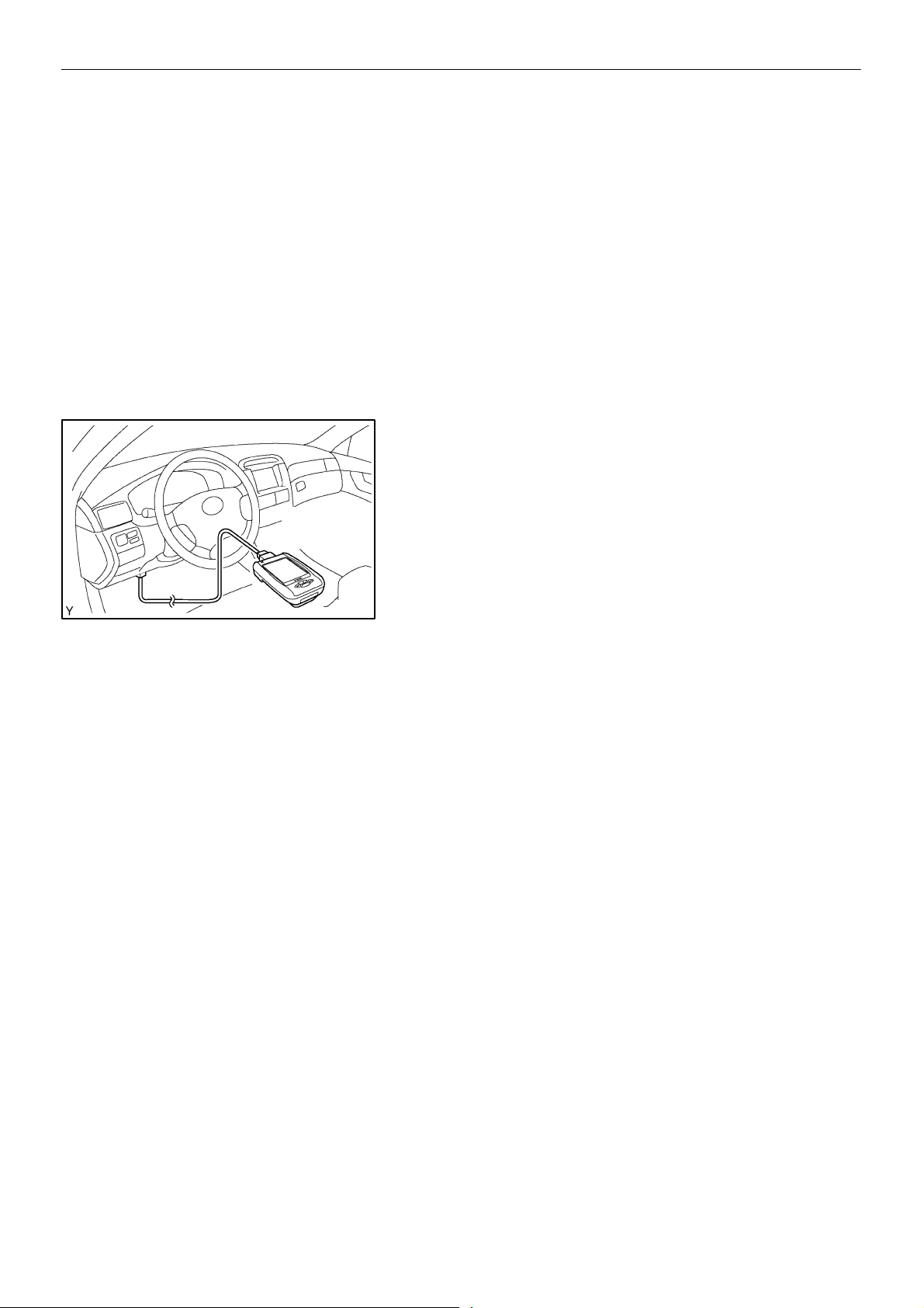
CHECK FUEL PUMP OPERATION AND FUEL LEAKS
11.
(a) Connect the Intelligent Tester II to the Data Link Connec-
tor 3 (DLC3).
(b) Turn the ignition switch ON and push the intelligent tester
II main switch ON.
NOTICE:
Do not start the engine.
(c) Select the active test mode on the Intelligent Tester II.
(d) Please refer to the Intelligent Tester II operator’s manual
for further details.
(e) Check that there is pressure in the fuel inlet hose from the
fuel filter.
HINT:
If there is fuel pressure, you will hear the sound of fuel flowing.
If there is no pressure, check the fusible link, fuses, EFI MAIN
relay, fuel pump, ECM and wiring connections.
(f) Check that there are no fuel leaks after doing mainte-
nance anywhere on the fuel system.
(1) Check that there are no leaks from any part of the
fuel system.
(g) Turn the ignition switch to OFF.
(h) Disconnect the Intelligent Tester II from the DLC3.
12. RESET RADIO STATION PRESETS AND CUSTOMER
SETTINGS
13. ADD FUEL IF REMOVED AS PER STEP 3
(Replacement)
10
 Loading...