

Page 1

Pictorial index
Search by illustration
For safety
and security
Vehicle status
information and
indicators
Before driving
Driving
Interior features
Maintenance
and care
When trouble
arises
Vehicle
specifications
Make sure to read through them
(Main topics: Child seat, theft deterrent system)
Reading driving-related information
(Main topics: Meters, multi-information display)
Opening and closing the doors and windows,
adjustment before driving
(Main topics: Keys, doors, seats)
Operations and advice which are necessary for driving
(Main topics: Starting engine, refueling)
Usage of the interior features
(Main topics: Air conditioner, storage features)
Caring for your vehicle and maintenance procedures
(Main topics: Interior and exterior, light bulbs)
What to do in case of malfunction and emergency
(Main topics: Battery discharge, flat tire)
Vehicle specifications, customizable features
(Main topics: Fuel, oil, tire inflation pressure)
1
2
3
4
5
6
7
8
For owners
Index
Reporting safety defects for U.S. owners, and seat belt,
SRS airbag and headlight aim instructions for Canadian
owners
Search by symptom
Search alphabetically
9
Page 2

2
TABLE OF CONTENTS
For your information ......................................6
Reading this manual.................................... 10
How to search .................................................11
Pictorial index .................................................12
1
For safety and security
1-1. For safe use
Before driving....................................24
For safe driving..................................25
Seat belts .............................................26
SRS airbags ....................................... 30
Front passenger occupant classifi-
cation system ................................. 39
Exhaust gas precautions .............. 43
1-2. Child safety
Riding with children........................ 44
Child restraint systems ................. 44
1-3. LEXUS Enform
Lexus Enform Safety Connect .. 56
1-4. Theft deterrent system
Engine immobilizer system...........61
Alarm.................................................... 63
Theft prevention labels (for the
U.S.A.)............................................... 64
3
Before driving
3-1. Key information
Keys.......................................................92
3-2. Opening, closing and locking the
doors
Side doors...........................................96
Back door......................................... 100
Smart access system with push-but-
ton start ............................................112
3-3. Adjusting the seats
Front seats..........................................119
Rear seats......................................... 120
Driving position memory.............121
Head restraints ...............................124
3-4. Adjusting the steering wheel and
mirrors
Steering wheel ................................127
Inside rear view mirror ............... 128
Outside rear view mirrors......... 130
3-5. Opening, closing the windows and
moon roof
Power windows ............................. 133
Moon roof........................................ 135
Vehicle status information and
2
indicators
2-1. Instrument cluster
Warning lights and indicators.... 66
Gauges and meters (except F
SPORT models) ........................... 70
Gauges and meters (F SPORT
models)............................................. 73
Multi-information display..............77
Head-up display .............................. 84
Fuel consumption information... 88
4
Driving
4-1. Before driving
Driving the vehicle........................ 140
Cargo and luggage...................... 145
Vehicle load limits......................... 148
Trailer towing.................................. 148
Dinghy towing................................ 149
4-2. Driving procedures
Engine (ignition) switch.............. 150
Page 3
TABLE OF CONTENTS
3
Continuously variable transmission
............................................................ 154
Turn signal lever............................. 158
Parking brake .................................159
Brake Hold....................................... 162
ASC (Active Sound Control).. 163
4-3. Operating the lights and wipers
Headlight switch............................ 164
Automatic High Beam................ 167
Fog light switch ..............................170
Windshield wipers and washer 171
Rear window wiper and washer
............................................................ 175
4-4. Refueling
Opening the fuel tank cap......... 177
4-5. Using the driving support systems
Lexus Safety System + 2.0........ 179
PCS (Pre-Collision System).....185
LTA (Lane Tracing Assist)......... 192
RSA (Road Sign Assist)..............201
Dynamic radar cruise control with
full-speed range.........................203
BSM (Blind Spot Monitor) ........213
PKSA (Parking Support Alert) 218
Intuitive parking assist ................. 219
RCTA (Rear Cross Traffic Alert)
function.......................................... 226
PKSB (Parking Support Brake)231
Parking Support Brake function
(static objects) ............................235
Parking Support Brake function
(rear-crossing vehicles)..........240
Driving mode select switch...... 243
Driving assist systems................. 244
4-6. Driving tips
Winter driving tips .......................249
Utility vehicle precautions.........252
5
Interior features
5-1. Remote Touch
Remote Touch............................... 256
5-2. Lexus Climate Concierge
Lexus Climate Concierge..........261
5-3. Using the air conditioning system
and defogger
Automatic air conditioning system
.......................................................... 263
Heated steering wheel/seat heat-
ers/seat ventilators....................272
5-4. Using the interior lights
Interior lights list ........................... 275
5-5. Using the storage features
List of storage features ..............278
Luggage compartment features
........................................................... 281
5-6. Using the other interior features
Other interior features ..............286
Garage door opener ................. 296
Compass .......................................... 301
6
Maintenance and care
6-1. Maintenance and care
Cleaning and protecting the vehi-
cle exterior................................... 306
Cleaning and protecting the vehi-
cle interior.................................... 30
6-2.
Maintenance
Maintenance requirements.......312
General maintenance................. 313
1
2
3
4
5
6
7
8
9
9
Page 4

4
TABLE OF CONTENTS
Emission inspection and mainte-
nance (I/M) programs .............316
6-3. Do-it-yourself maintenance
Do-it-yourself service precautions
............................................................ 317
Hood................................................... 319
Positioning a floor jack............... 320
Engine compartment................... 321
Tires ................................................... 328
Tire inflation pressure................. 337
Wheels.............................................. 339
Air conditioning filter.................. 340
Electronic key battery................. 341
Checking and replacing fuses 343
Headlight aim................................. 345
Light bulbs....................................... 346
7
When trouble arises
7-1. Essential information
Emergency flashers.....................350
If your vehicle has to be stopped in
an emergency.............................350
If the vehicle is trapped in rising
water................................................ 351
7-2. Steps to take in an emergency
If your vehicle needs to be towed
........................................................... 353
If you think something is wrong
........................................................... 356
Fuel pump shut off system ........357
If a warning light turns on or a warn-
ing buzzer sounds.....................358
If a warning message is displayed
........................................................... 367
If you have a flat tire (vehicles with
spare tire) .....................................370
If you have a flat tire (vehicles with-
out spare tire) ............................. 377
If the engine will not start.......... 378
If you lose your keys.................... 379
If the fuel filler door cannot be
opened ..........................................380
If the electronic key does not oper-
ate properly.................................380
If the vehicle battery is discharged
.......................................................... 382
If your vehicle overheats........... 386
If the vehicle becomes stuck ...388
8
Vehicle specifications
8-1. Specifications
Maintenance data (fuel, oil level,
etc.) .................................................390
Fuel information............................ 397
Tire information ............................ 399
8-2. Customization
Customizable features ..............408
8-3. Initialization
Items to initialize............................ 419
9
For owners
9-1. For owners
Reporting safety defects for U.S.
owners............................................422
Seat belt instructions for Canadian
owners (in French) ....................422
SRS airbag instructions for Cana-
dian owners (in French) ..........424
Headlight aim instructions for
Canadian owners (
n French)430
i
Page 5

Index
What to do if... (Troubleshooting)
........................................................... 434
Alphabetical Index ...................... 437
TABLE OF CONTENTS
5
1
2
3
4
5
6
7
8
9
Page 6

6
WARNING
For your information
■ General precautions while driving
Driving under the influence: Never drive
your vehicle when under the influence of
alcohol or drugs that have impaired your
ability to operate your vehicle. Alcohol
and certain drugs delay reaction time,
impair judgment and reduce coordination, which could lead to an accident that
could result in death or serious injury.
Defensive driving: Always drive defensively. Anticipate mistakes that other
drivers or pedestrians might make and
be ready to avoid accidents.
Driver distraction: Always give your full
attention to driving. Anything that distracts the driver, such as adjusting controls, talking on a cellular phone or
reading can result in a collision with
resulting death or serious injury to you,
your occupants or others.
■ General precaution regarding chil-
dren’s safety
Never leave children unattended in the
vehicle, and never allow children to have
or use the key.
Children may be able to start the vehicle
or shift the vehicle into neutral. There is
also a danger that children may injure
themselves by playing with the windows,
the moon roof, or other features of the
vehicle. In addition, heat build-up or
extremely cold temperatures inside the
vehicle can be fatal to children.
Main Owner’s Manual
Please note that this manual applies to
all models and explains all equipment,
including options. Therefore, you may
find some explanations for equipment
not installed on your vehicle.
All specifications provided in this man-
ual are current at the time of printing.
However, because of the Lexus policy
of continual product improvement, we
reserve the right to make changes at
any time without notice.
Depending on specifications, the vehicle shown in the illustrations may differ
from your vehicle in terms of color and
equipment.
Noise from under vehicle after
turning off the engine
Approximately five hours after the
engine is turned off, you may hear
sound coming from under the vehicle
for several minutes. This is the sound of
a fuel evaporation leakage check and,
it does not indicate a malfunction.
Accessories, spare parts and
modification of your Lexus
A wide variety of non-genuine spare
parts and accessories for Lexus vehicles are currently available in the market. You should know that Toyota does
not warrant these products and is not
responsible for their performance,
repair, or replacement, or for any damage they may cause to, or adverse
effect they may have on, your Lexus
vehicle.
This vehicle should not be modified
with non-genuine Lexus products.
Modification with non-genuine Lexus
products could affect its performance,
safety or durability, and may even violate governmental regulations. In addi-
Page 7

7
tion, damage or performance
problems resulting from the modification may not be covered under warranty.
Installation of a mobile two-way
radio system
The installation of a mobile two-way
radio system in your vehicle could
affect electronic systems such as:
Multiport fuel injection sys-
tem/sequential multiport fuel injection system
Lexus Safety System + 2.0
Anti-lock brake system
SRS airbag system
Seat belt pretensioner system
Be sure to check with your Lexus
dealer for precautionary measures or
special instructions regarding installation of a mobile two-way radio system.
Vehicle data recording
The vehicle is equipped with sophisticated computers that will record certain data, such as:
• Engine speed/Electric motor speed
(traction motor speed)
• Accelerator status
•Brake status
• Vehicle speed
• Operation status of the driving
assist systems
• Images from the cameras
Your vehicle is equipped with cameras. Contact your Lexus dealer for
the location of recording cameras
The recorded data varies according to
the vehicle grade level and options
with which it is equipped.
These computers do not record conversations or sounds, and only record
images outside of the vehicle in certain
situations.
Data Transmission
Your vehicle may transmit the data
recorded in these computers to Lexus
without notification to you.
Data usage
Lexus may use the data recorded in this
computer to diagnose malfunctions, conduct research and development, and
improve quality.
Lexus will not disclose the recorded data to
a third party except:
• With the consent of the vehicle owner or
with the consent of the lessee if the vehicle is leased
• In response to an official request by the
police, a court of law or a government
agency
• For use by Lexus in a lawsuit
• For research purposes where the data is
not tied to a specific vehicle or vehicle
owner
Recorded image information can be
erased by your Lexus dealer
The image recording function can be disabled. However, if the function is disabled,
data from when the system operates will
not be available.
To learn more about the vehicle data
collected, used and shared by
Lexus, please visit
Page 8

8
www.lexus.com/privacyvts/.
Usage of data collected through
Lexus Enform (U.S. mainland only)
If your Lexus has Lexus Enform and if
you have subscribed to those services,
please refer to the Lexus Enform
Telematics Subscription Service
Agreement for information on data
collected and its usage.
To learn more about the vehicle data
collected, used and shared by
Lexus, please visit
www.lexus.com/privacyvts/
.
Event data recorder
This vehicle is equipped with an event
data recorder (EDR). The main purpose of an EDR is to record, in certain
crash or near crash-like situations, such
as an air bag deployment or hitting a
road obstacle, data that will assist in
understanding how a vehicle’s systems
performed. The EDR is designed to
record data related to vehicle dynamics and safety systems for a short
period of time, typically 30 seconds or
less.
The EDR in this vehicle is designed to
record such data as:
• How various systems in your vehicle
were operating;
• Whether or not the driver and passenger safety belts were buckled/fastened;
• How far (if at all) the driver was
depressing the accelerator and/or
brake pedal; and,
• How fast the vehicle was traveling.
These data can help provide a better
understanding of the circumstances in
which crashes and injuries occur.
NOTE: EDR data are recorded by your
vehicle only if a non-trivial crash situation occurs; no data are recorded by
the EDR under normal driving conditions and no personal data (e.g., name,
gender, age, and crash location) are
recorded. However, other parties, such
as law enforcement, could combine the
EDR data with the type of personally
identifying data routinely acquired
during a crash investigation.
To read data recorded by an EDR, special equipment is required, and access
to the vehicle or the EDR is needed. In
addition to the vehicle manufacturer,
other parties, such as law enforcement,
that have the special equipment, can
read the information if they have
access to the vehicle or the EDR.
Disclosure of the EDR data
Lexus will not disclose the data recorded in
an EDR to a third party except when:
• An agreement from the vehicle’s owner
(or the lessee for a leased vehicle) is
obtained
• In response to an official request by the
police, a court of law or a government
agency
• For use by Lexus in a lawsuit
However, if necessary, Lexus may:
• Use the data for research on vehicle
safety performance
Page 9

• Disclose the data to a third party for
research purposes without disclosing
information about the specific vehicle or
vehicle owner
Scrapping of your Lexus
The SRS airbag and seat belt pretensioner devices in your Lexus contain
explosive chemicals. If the vehicle is
scrapped with the airbags and seat belt
pretensioners left as they are, this may
cause an accident such as fire. Be sure
to have the systems of the SRS airbag
and seat belt pretensioner removed
and disposed of by a qualified service
shop or by your Lexus dealer before
you scrap your vehicle.
Perchlorate Material
9
Special handling may apply, See
www.dtsc.ca.gov/hazardouswaste/
perchlorate.
Your vehicle has components that may
contain perchlorate. These components may include airbag, seat belt pretensioners, and wireless remote
control batteries.
Page 10
10
Reading this manual
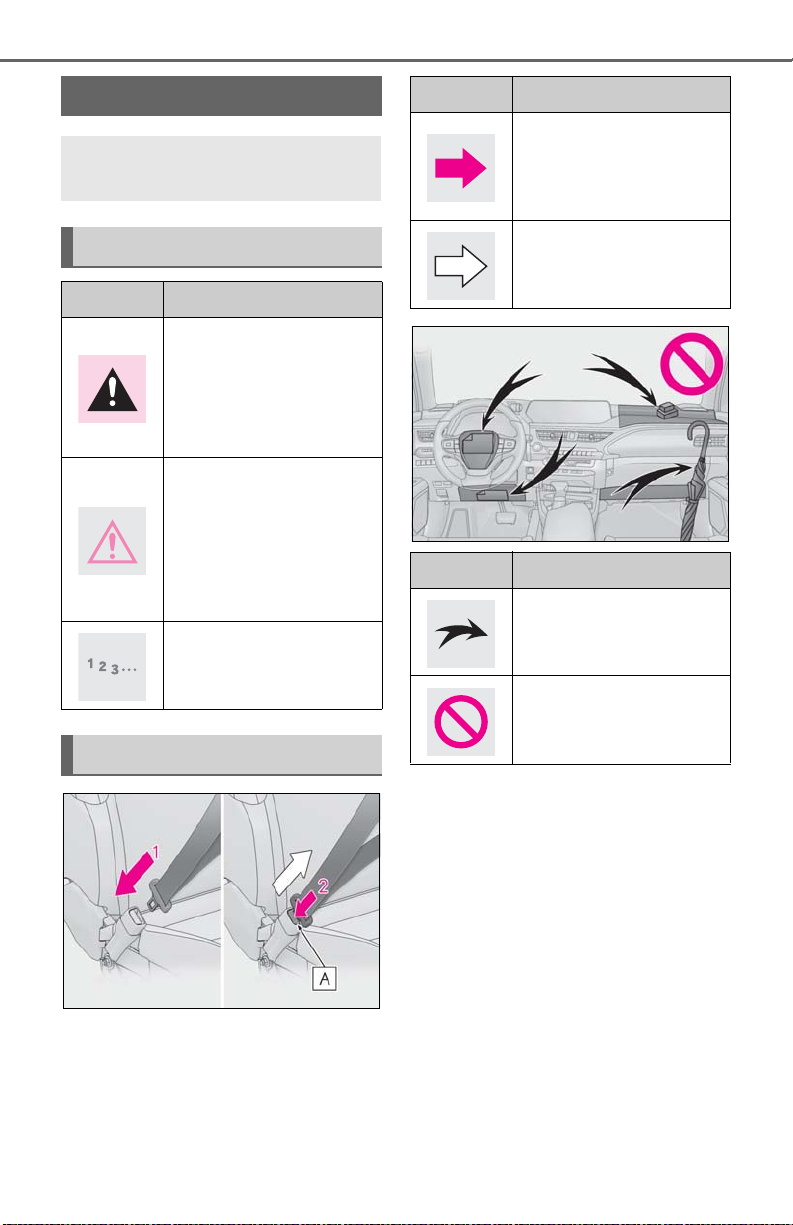
Explains symbols used in this manual
Symbols in this manual
Symbols Meanings
WARNING:
Explains something that, if
not obeyed, could cause
death or serious injury to
people.
NOTICE:
Explains something that, if
not obeyed, could cause
damage to or a malfunction
in the vehicle or its equipment.
Indicates operating or working procedures. Follow the
steps in numerical order.
Symbols in illustrations
Symbols Meanings
Indicates the action (pushing, turning, etc.) used to
operate switches and other
devices.
Indicates the outcome of an
operation (e.g. a lid opens).
Symbols Meanings
Indicates the component or
position being explained.
Means Do not, Do not do
this, or Do not let this happen.
Page 11

How to search
■ Searching by name
Alphabetical index: P.437
■ Searching by installation position
Pictorial index: P.12
11
■ Searching by symptom or sound
What to do if... (Troubleshooting):
P.434
■ Searching by title
Table of contents: P.2
Page 12
12
A
B
C
Pictorial index
Pictorial index
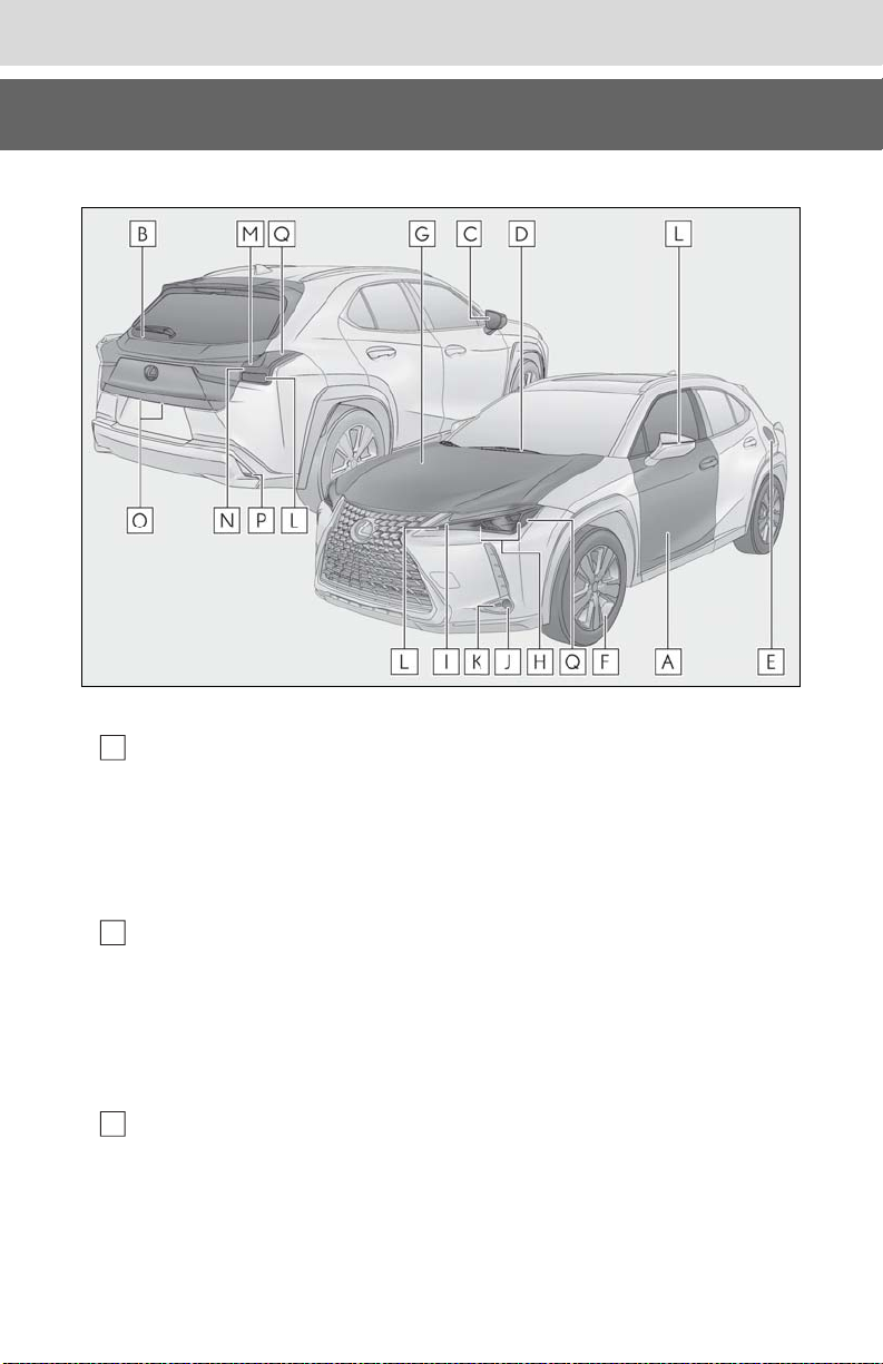
■Exterior
The shape of the headlights may differ depending on the grade, etc.
Side doors.................................................................................................................... P.96
Locking/unlocking..............................................................................................................P.96
Opening/closing the side windows........................................................................... P.133
Locking/unlocking by using the mechanical key...............................................P.380
Warning messages ..........................................................................................................P.367
Back door ..................................................................................................................P.100
Locking/unlocking..............................................................................................................P.101
Opening/closing the back door....................................................................................P.101
Power back door
Warning messages ..........................................................................................................P.367
Outside rear view mirrors ....................................................................................P.130
Adjusting the mirror angle.............................................................................................P.130
Folding the mirrors..............................................................................................................P.131
Driving position memory
Defogging the mirrors....................................................................................................P.264
*
..............................................................................................................P.103
*
................................................................................................P.121
Page 13

Pictorial index
D
E
F
G
H
I
J
K
L
M
N
O
P
Windshield wipers ................................................................................................... P.171
Precautions against winter season............................................................................P.249
To prevent freezing (windshield wiper de-icer)
Precautions against car wash (rain-sensing windshield wipers)
*
.................................................P.268
*
.................P.307
Fuel filler door .......................................................................................................... P.177
Refueling method ...............................................................................................................P.177
Fuel type/fuel tank capacity .......................................................................................... P.391
Tires...........................................................................................................................P.328
Tire size/inflation pressure ...........................................................................................P.395
Winter tires/tire chain ....................................................................................................P.249
Checking/rotation/tire pressure warning system..............................................P.328
Coping with flat tires.............................................................................................P.370, 377
Hood ........................................................................................................................... P.319
Opening ................................................................................................................................ P.319
Engine oil..............................................................................................................................P.392
Coping with overheat .....................................................................................................P.386
Warning messages ..........................................................................................................P.367
13
Light bulbs of the exterior lights for driving
(Replacing method: P.346, Watts: P.396)
Headlights ................................................................................................................. P.164
Parking lights/daytime running lights............................................................... P.164
Fog lights
Cornering lights
*
.................................................................................................................. P.170
*
..................................................................................................... P.166
Turn signal lights ......................................................................................................P.158
Tail lights/stop lights............................................................................................... P.164
Stop lights
License plate lights ................................................................................................. P.164
Back-up lights
Shifting the shift lever to R..............................................................................................P.154
Page 14

14
Q
*
:If equipped
Pictorial index
Side marker lights ................................................................................................... P.164
Page 15
■Instrument panel
A
B
C
D
Pictorial index
15
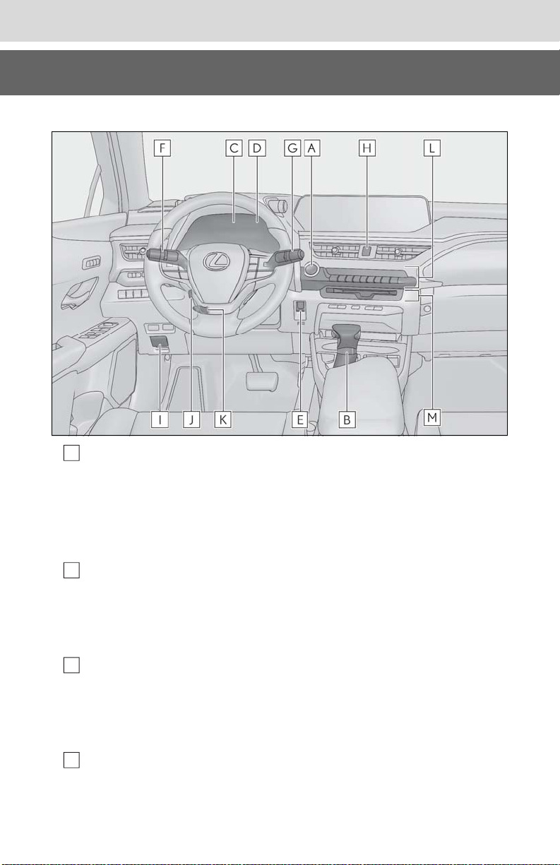
Engine switch ...........................................................................................................P.150
Starting the engine/changing the modes................................................................P.150
Emergency stop of the engine ....................................................................................P.350
When the engine will not start.....................................................................................P.378
Warning messages ..........................................................................................................P.367
Shift lever................................................................................................................... P.154
Changing the shift position............................................................................................P.155
Precautions against towing...........................................................................................P.353
When the shift lever does not move ..........................................................................P.156
Meters .................................................................................................................. P.70, 73
Reading the meters/adjusting the instrument panel lights.........P.70, 72, 73, 76
Warning lights/indicator lights ......................................................................................P.66
When the warning lights come on.............................................................................P.358
Multi-information display ....................................................................................... P.77
Display.......................................................................................................................................P.77
When the warning messages are displayed..........................................................P.367
Page 16

16
E
F
GHI
J
K
L
M
Pictorial index
Parking brake switch ............................................................................................. P.159
Applying/releasing ...........................................................................................................P.159
Precautions against winter season............................................................................P.250
Warning buzzer/message................................................................................ P.360, 367
Turn signal lever ...................................................................................................... P.158
Headlight switch...................................................................................................... P.164
Headlights/parking lights/tail lights/license plate lights/
daytime running lights.......................................................................................................P.164
Automatic High Beam......................................................................................................P.167
Fog lights
*1
............................................................................................................................ P.170
Windshield wiper and washer switch ................................................................. P.171
Rear window wiper and washer switch ............................................................ P.175
Usage.............................................................................................................................. P.171, 175
Adding washer fluid......................................................................................................... P.327
Headlight cleaners
*1
...........................................................................................................P.171
Warning messages ..........................................................................................................P.367
Emergency flasher switch .................................................................................. P.350
Hood lock release lever ........................................................................................ P.319
*1
Tilt and telescopic steering control switch
................................................... P.127
Adjustment ............................................................................................................................P.127
Driving position memory
Tilt and telescopic steering lock release lever
*1
...............................................................................................P.121
*1
............................................ P.127
Adjustment ............................................................................................................................P.127
Air conditioning system .......................................................................................P.263
Usage.....................................................................................................................................P.263
Rear window defogger...................................................................................................P.264
Audio system
*1
: If equipped
*2
: Refer to “NAVIGATION AND MULTIMEDIA SYSTEM OWNER’S MANUAL”.
*2
Page 17
Pictorial index
A
B
C
D
E
F
G
H
I
J
K
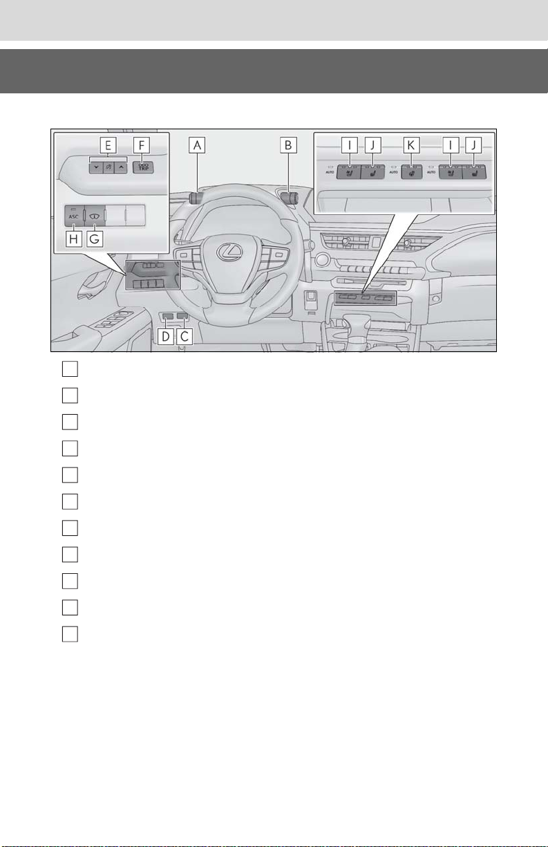
■Switches
VSC off switch.........................................................................................................P.245
Driving mode select switch .................................................................................P.243
*
Power back door switch
......................................................................................P.103
17
Fuel filler door opener switch.............................................................................. P.177
Instrument panel light control switches ......................................................P.72, 76
Odometer/trip meter and trip meter reset button .................................. P.71, 76
*
Head-up display switch
*
ASC switch
.............................................................................................................. P.163
Seat ventilator switches
Seat heater switches
Heated steering wheel switch
*
:If equipped
......................................................................................... P.84
*
..................................................................................... P.273
*
........................................................................................... P.273
*
..........................................................................P.272
Page 18
18
A
B
C
D
E
A
B
C
Pictorial index
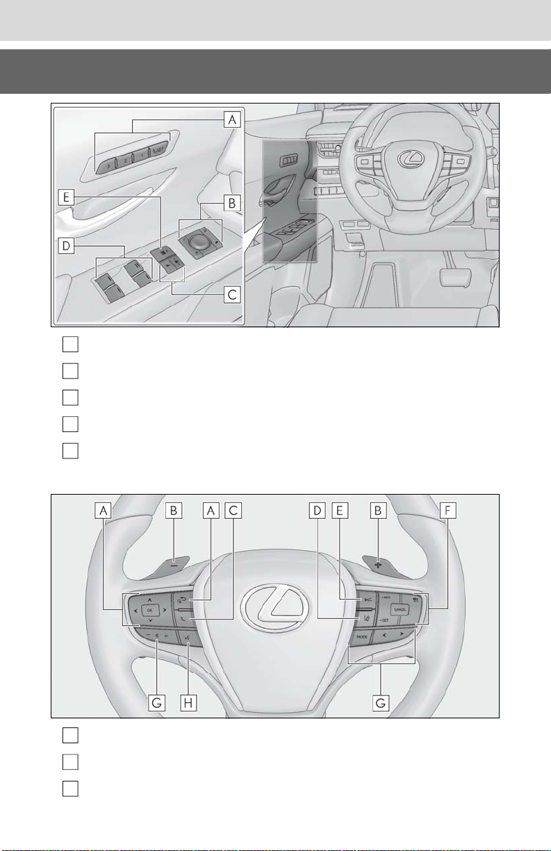
Driving position memory switches*................................................................... P.122
Outside rear view mirror switches ....................................................................P.130
Door lock switches .................................................................................................. P.98
Power window switches ........................................................................................P.133
Window lock switch ............................................................................................... P.134
*
:If equipped
Meter control switches ........................................................................................... P.79
*1
Paddle shift switches
TEL switch
*2
..................................................................................P.156, 157
Page 19

Pictorial index
D
E
F
G
H
A
B
C
LTA (Lane Tracing Assist) switch ....................................................................... P.192
Vehicle-to-vehicle distance switch ................................................................. P.208
Cruise control switches
Dynamic radar cruise control with full-speed range .........................................P.203
Audio remote control switches
Talk switch
*1
: If equipped
*2
: Refer to “NAVIGATION AND MULTIMEDIA SYSTEM OWNER’S MANUAL”.
*2
*2
19
Remote Touch.........................................................................................................P.256
Audio control switches
*
Brake hold switch .................................................................................................... P.162
*
: Refer to “NAVIGATION AND MULTIMEDIA SYSTEM OWNER’S MANUAL”.
Page 20
20
A
B
C
D
E
F
G
H
I
J
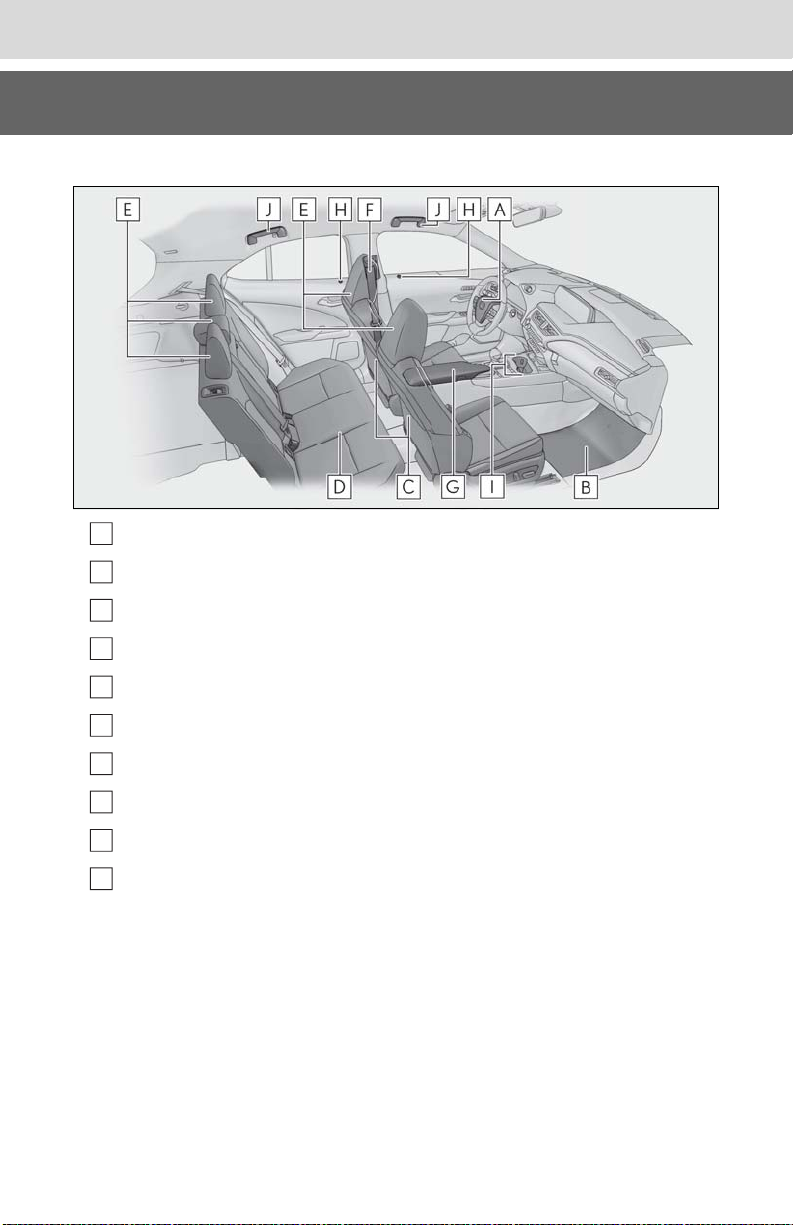
■Interior
Pictorial index
SRS airbags................................................................................................................ P.30
Floor mats .................................................................................................................... P.24
Front seats .................................................................................................................. P.119
Rear seats ..................................................................................................................P.120
Head restraints ........................................................................................................ P.124
Seat belts .....................................................................................................................P.26
Console box............................................................................................................. P.279
Inside lock buttons ................................................................................................... P.98
Cup holders ............................................................................................................. P.279
Assist grips ...............................................................................................................P.295
Page 21
Pictorial index
A
B
C
D
E
F
G
H
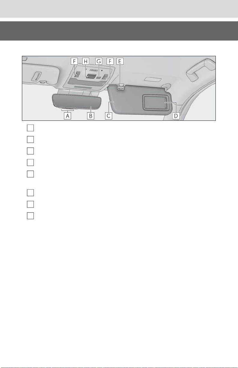
■Ceiling
Garage door opener buttons*1..........................................................................P.296
Inside rear view mirror ..........................................................................................P.128
Sun visors..................................................................................................................P.286
Vanity mirrors .........................................................................................................P.286
*2
Interior light
Personal lights......................................................................................................... P.277
Moon roof switches
......................................................................................................... P.276
*1
............................................................................................. P.135
21
Door-linked interior light switch ....................................................................... P.276
*1
“SOS” button
*1
: If equipped
*2
: The illustration shows the front, but they are also equipped in the rear.
........................................................................................................... P.56
Page 22

22
Pictorial index
Page 23

23
For safety and security
1-1. For safe use
Before driving.................................24
For safe driving.............................. 25
Seat belts ......................................... 26
SRS airbags .................................... 30
Front passenger occupant classifi-
cation system .............................. 39
Exhaust gas precautions ........... 43
1-2. Child safety
Riding with children..................... 44
Child restraint systems .............. 44
1-3. LEXUS Enform
Lexus Enform Safety Connect 56
1-4. Theft deterrent system
Engine immobilizer system....... 61
Alarm................................................. 63
Theft prevention labels (for the
U.S.A.)............................................ 64
1
1
For safety and security
Page 24
24
WARNING
1-1.For safe use
1-1. For safe use
Before driving
Observe the following before starting off in the vehicle to ensure
safety of driving.
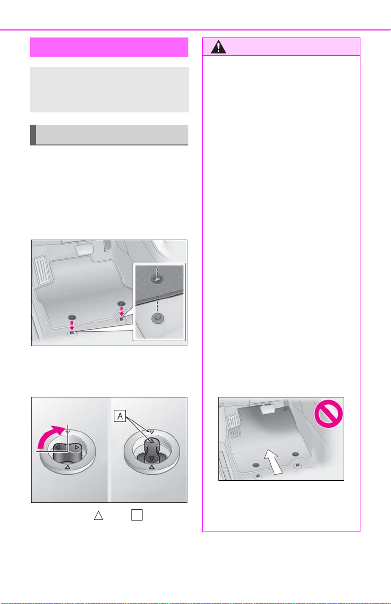
Installing floor mats
Use only floor mats designed specifically for vehicles of the same model
and model year as your vehicle. Fix
them securely in place onto the carpet.
1 Insert the retaining hooks (clips)
into the floor mat eyelets.
Observe the following precautions.
Failure to do so may cause the driver’s
floor mat to slip, possibly interfering with
the pedals while driving. An unexpectedly high speed may result or it may
become difficult to stop the vehicle. This
could lead to an accident, resulting in
death or serious injury.
■ When installing the driver’s floor mat
● Do not use floor mats designed for
other models or different model year
vehicles, even if they are Lexus Genuine floor mats.
● Only use floor mats designed for the
driver’s seat.
● Always install the floor mat securely
using the retaining hooks (clips) provided.
● Do not use two or more floor mats on
top of each other.
● Do not place the floor mat bottom-
side up or upside-down.
2 Turn the upper knob of each retain-
ing hook (clip) to secure the floor
mats in place.
Always align the marks .
The shape of the retaining hooks (clips)
may differ from that shown in the illustration.
A
■ Before driving
● Check that the floor mat is securely
fixed in the correct place with all the
provided retaining hooks (clips). Be
especially careful to perform this
check after cleaning the floor.
● With the engine stopped and the shift
lever in P, fully depress each pedal to
the floor to make sure it does not interfere with the floor mat.
Page 25
1-1. For safe use
WARNING
A
B
C
D
25
For safe driving
For safe driving, adjust the seat and
mirror to an appropriate position
before driving.
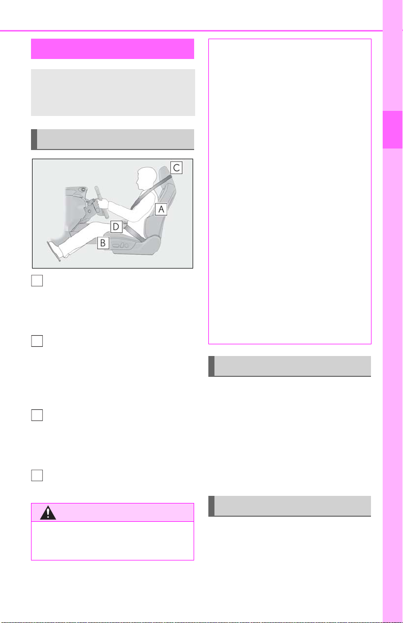
Correct driving posture
Adjust the angle of the seatback so
that you are sitting straight up and
so that you do not have to lean forward to steer. (P.119)
Adjust the seat so that you can
depress the pedals fully and so that
your arms bend slightly at the
elbow when gripping the steering
wheel. (P.119)
Lock the head restraint in place
with the center of the head restraint
closest to the top of your ears.
(P.124)
Wear the seat belt correctly.
(P.27)
● Do not adjust the position of the
driver’s seat while driving.
Doing so could cause the driver to lose
control of the vehicle.
● Do not place a cushion between the
driver or passenger and the seatback.
A cushion may prevent correct posture from being achieved, and reduce
the effectiveness of the seat belt and
head restraint.
● Do not place anything under the front
seats.
Objects placed under the front seats
may become jammed in the seat
tracks and stop the seat from locking in
place. This may lead to an accident
and the adjustment mechanism may
also be damaged.
● Always observe the legal speed limit
when driving on public roads.
● When driving over long distances, take
regular breaks before you start to feel
tired. Also, if you feel tired or sleepy
while driving, do not force yourself to
continue driving and take a break
immediately.
Correct use of the seat belts
Make sure that all occupants are wearing their seat belts before driving the
vehicle. (P.27)
Use a child restraint system appropriate for the child until the child becomes
large enough to properly wear the
vehicle’s seat belt. (P.44)
Adjusting the mirrors
1
For safety and security
Observe the following precautions.
Failure to do so may result in death or
serious injury.
Make sure that you can see the rear of
the vehicle clearly, by adjusting the
inside and outside rear view mirrors
properly. (P.128, 130)
Page 26

26
WARNING
1-1. For safe use
Seat belts
Make sure that all occupants are
wearing their seat belts before driving the vehicle.
Observe the following precautions to
reduce the risk of injury in the event of
sudden braking, sudden swerving or an
accident.
Failure to do so may cause death or serious injury.
■ Wearing a seat belt
● Ensure that all passengers wear a seat
belt.
● Always wear a seat belt properly.
● Each seat belt should be used by one
person only. Do not use a seat belt for
more than one person at once, including children.
● Lexus recommends that children be
seated in the rear seat and always use
a seat belt and/or an appropriate child
restraint system.
● To achieve a proper seating position,
do not recline the seat more than necessary. The seat belt is most effective
when the occupants are sitting up
straight and well back in the seats.
■ Pregnant women
Obtain medical advice and wear the seat
belt in the proper way. (P.27)
Women who are pregnant should position the lap belt as low as possible over
the hips in the same manner as other
occupants, extending the shoulder belt
completely over the shoulder and avoiding belt contact with the rounding of the
abdominal area.
If the seat belt is not worn properly, not
only the pregnant woman, but also the
fetus could suffer death or serious injury
as a result of sudden braking or a collision.
■ People suffering illness
Obtain medical advice and wear the seat
belt in the proper way. (P.27)
● Do not wear the shoulder belt under
your arm.
● Always wear your seat belt low and
snug across your hips.
■ When children are in the vehicle
P.52
■ Seat belt damage and wear
● Do not damage the seat belts by allow-
ing the belt, plate, or buckle to be
jammed in the door.
● Inspect the seat belt system periodi-
cally. Check for cuts, fraying, and loose
parts. Do not use a damaged seat belt
until it is replaced. Damaged seat belts
cannot protect an occupant from
death or serious injury.
Page 27
WARNING
● Ensure that the belt and plate are
WARNING
locked and the belt is not twisted.
If the seat belt does not function correctly, immediately contact your Lexus
dealer.
● Replace the seat assembly, including
the belts, if your vehicle has been
involved in a serious accident, even if
there’s no obvious damage.
● Do not attempt to install, remove,
modify, disassemble or dispose of the
seat belts. Have any necessary repairs
carried out by your Lexus dealer. Inappropriate handling may lead to incorrect operation.
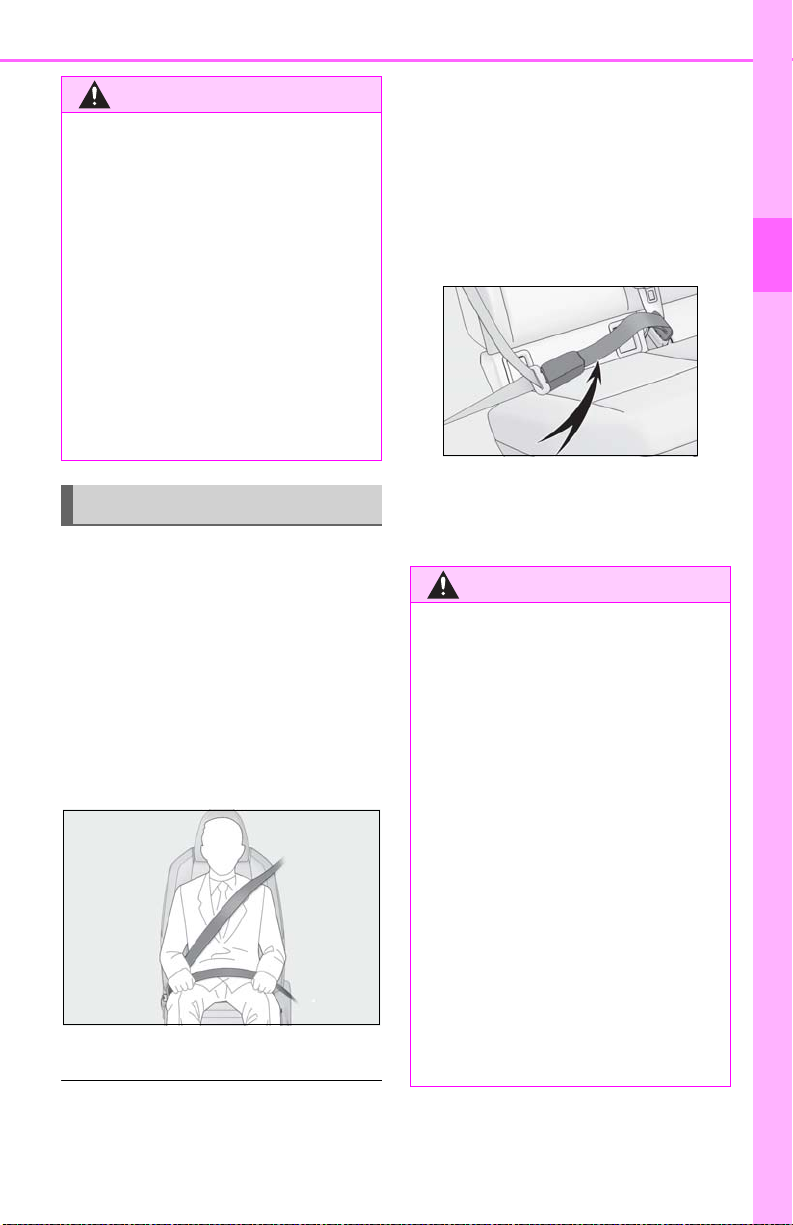
Correct use of the seat belts
Extend the shoulder belt so that it
comes fully over the shoulder, but
does not come into contact with the
neck or slide off the shoulder.
Position the lap belt as low as possi-
ble over the hips.
Adjust the position of the seatback.
Sit up straight and well back in the
seat.
1-1. For safe use
● Use a child restraint system appropriate
for the child, until the child becomes large
enough to properly wear the vehicle’s
seat belt. (P.44)
● When the child becomes large enough to
properly wear the vehicle’s seat belt, follow the instructions regarding seat belt
usage. (P.26)
■ Seat belt extender
If your seat belts cannot be fastened
securely because they are not long enough,
a personalized seat belt extender is available from your Lexus dealer free of charge.
■ Using a seat belt extender
Observe the following precautions to
reduce the risk of injury in the event of
sudden braking, sudden swerving or an
accident.
Failure to do so may cause death or serious injury.
● Do not wear the seat belt extender if
you can fasten the seat belt without the
extender.
27
1
For safety and security
Do not twist the seat belt.
■ Child seat belt usage
The seat belts of your vehicle were principally designed for persons of adult size.
● Do not use the seat belt extender
when installing a child restraint system
because the belt will not securely hold
the child restraint system, increasing
the risk of death or serious injury in the
event of an accident.
● The personalized extender may not be
safe on another vehicle, when used by
another person, or at a different seating position other than the one originally intended.
Page 28

28
NOTICE
WARNING
■ When using a seat belt extender
When releasing the seat belt, press on
the buckle release button on the
extender, not on the seat belt.
This helps prevent damage to the vehicle
interior and the extender itself.
1-1. For safe use
Fastening and releasing the seat
belt
1 To fasten the seat belt, push the
plate into the buckle until a click
sound is heard.
2 To release the seat belt, press the
release button .
■ Emergency locking retractor (ELR)
The retractor will lock the belt during a sudden stop o r on impa ct. It ma y also lock if y ou
lean forward too quickly. A slow, easy
motion will allow the belt to extend so that
you can move around fully.
■ Automatic locking retractor (ALR)
When a passenger’s shoulder belt is completely extended and then retracted even
slightly, the belt is locked in that position and
cannot be extended. This feature is used to
hold the child restraint system (CRS) firmly.
To free the belt again, fully retract the belt
and then pull the belt out once more.
A
Adjusting the seat belt shoulder
anchor height (front seats)
1 Push the seat belt shoulder anchor
down while pressing the release
button .
2 Push the seat belt shoulder anchor
up.
Move the height adjuster up and down as
needed until you hear a click.
■ Adjustable shoulder anchor
Always make sure the shoulder belt is
positioned across the center of your
shoulder. The belt should be kept away
from your neck, but not falling off your
shoulder. Failure to do so could reduce
the amount of protection in an accident
and cause death or serious injuries in the
event of a sudden stop, sudden swerve or
accident.
A
Page 29

Seat belt pretensioners (front
WARNING
and outboard rear seats)
The pretensioners help the seat belts to
quickly restrain the occupants by
retracting the seat belts when the vehicle is subjected to certain types of
severe frontal or side collision or a
vehicle rollover.
The pretensioners do not activate in the
event of a minor frontal impact, a minor
side impact or a rear impact.
1-1. For safe use
■ Seat belt pretensioners
Observe the following precautions to
reduce the risk of injury in the event of
sudden braking, sudden swerving or an
accident.
Failure to do so may cause death or serious injury.
● Do not place anything, such as a cush-
ion, on the front passenger’s seat.
Doing so will disperse the passenger’s
weight, which prevents the sensor
from detecting the passenger’s weight
properly. As a result, the seat belt pretensioner for the front passenger’s seat
may not activate in the event of a collision.
● If the pretensioner has activated, the
SRS warning light will come on. In that
case, the seat belt cannot be used
again and must be replaced at your
Lexus dealer.
29
1
For safety and security
■ Replacing the belt after the preten-
sioner has been activated
If the vehicle is involved in multiple collisions, the pretensioner will activate for the
first collision, but will not activate for the
second or subsequent collisions.
Page 30
30
A
BCD
1-1. For safe use
SRS airbags
The SRS airbags inflate when the vehicle is subjected to certain types of severe
impacts that may cause significant injury to the occupants. They work together
with the seat belts to help reduce the risk of death or serious injury.
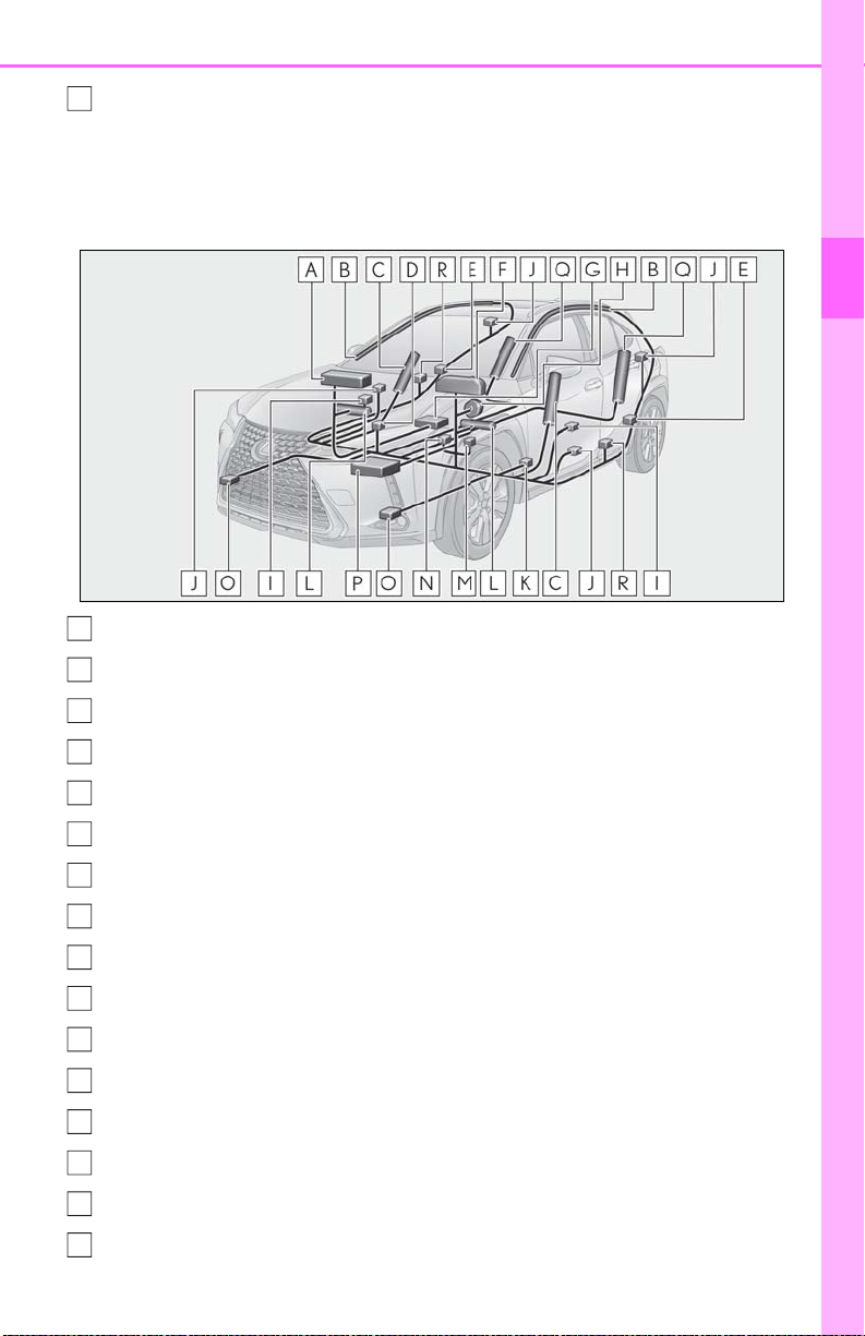
SRS airbag system
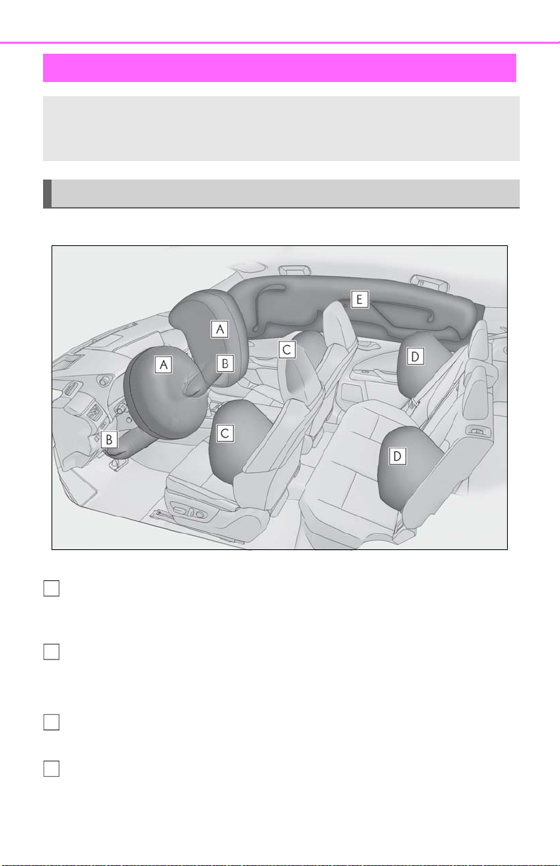
■ Location of the SRS airbags
SRS front airbags
SRS driver airbag/front passenger airbag
Can help protect the head and chest of the driver and front passenger from impact with
interior components
SRS knee airbags
Can help provide driver and front passenger protection
SRS side and curtain shield airbags
SRS front side airbags
Can help protect the torso of the front seat occupants
SRS rear side airbags
Can help protect the torso of occupants in the rear outer seats
Page 31
1-1. For safe use
E
A
B
C
D
E
F
G
H
I
J
K
L
M
N
O
P
SRS curtain shield airbags
• Can help protect primarily the head of occupants in the outer seats
• Can help prevent the occupants from being thrown from the vehicle in the event of vehicle rollover
■ SRS airbag system components
Front passenger airbag
Curtain shield airbags
31
1
For safety and security
Front side airbags
“AIR BAG ON” and “AIR BAG OFF” indicator lights
Side impact sensors (rear)
SRS warning light
Front passenger occupant classification system (ECU and sensors)
Driver airbag
Side impact sensors (front)
Seat belt pretensioners and force limiters
Driver’s seat position sensor
Knee airbags
Driver’s seat belt buckle switch
Front passenger’s seat belt buckle switch
Front impact sensors
Airbag sensor assembly
Page 32

32
Q
R
1-1. For safe use
Rear side airbags
Side impact sensors (front door)
Your vehicle is equipped with ADVANCED AIRBAGS designed based on the US
motor vehicle safety standards (FMVSS208). The airbag sensor assembly (ECU)
controls airbag deployment based on information obtained from the sensors etc.
shown in the system components diagram above. This information includes crash
severity and occupant information. As the airbags deploy, a chemical reaction in
the inflators quickly fills the airbags with non-toxic gas to help restrain the motion of
the occupants.
■ If the SRS airbags deploy (inflate)
● Slight abrasions, burns, bruising etc., may
be sustained from SRS airbags, due to the
extremely high speed deployment (inflation) by hot gases.
● A loud noise and white powder will be
emitted.
● Parts of the airbag module (steering
wheel hub, airbag cover and inflator) as
well as the front seats, parts of the front
and rear pillars, and roof side rails, may
be hot for several minutes. The airbag
itself may also be hot.
● The windshield may crack.
● All of the doors will be unlocked. (P.97)
● The brakes and stop lights will be con-
trolled automatically. (P.245)
● The interior lights will turn on automati-
cally. (P.276)
● The emergency flashers will turn on auto-
matically. (P.350)
● Fuel supply to the engine will be stopped.
(P.357)
● For Lexus Enform Safety Connect sub-
scribers, if any of the following situations
occur, the system is designed to send an
emergency call to the response center,
notifying them of the vehicle’s location
(without needing to push the “SOS” button) and an agent will attempt to speak
with the occupants to ascertain the level
of emergency and assistance required. If
the occupants are unable to communicate, the agent automatically treats the
call as an emergency and helps to dis-
patch the necessary emergency services.
(P.56)
• An SRS airbag is deployed.
• A seat belt pretensioner is activated.
• The vehicle is involved in a severe rearend collision.
■ SRS airbag deployment conditions (SRS
front airbags)
● The SRS front airbags will deploy in the
event of an impact that exceeds the set
threshold level (the level of force corresponding to an approximately 12 - 18
mph [20 - 30 km/h] frontal collision with
a fixed wall that does not move or
deform).
However, this threshold velocity will be considerably higher in the following situations:
• If the vehicle strikes an object, such as a
parked vehicle or sign pole, which can
move or deform on impact
• If the vehicle is involved in an underride
collision, such as a collision in which the
front of the vehicle underrides, or goes
under, the bed of a truck
● Depending on the type of collision, it is
possible that only the seat belt pretensioners will activate.
● The SRS front airbags for the front pas-
senger will not activate if there is no passenger sitting in the front passenger seat.
However, the SRS front airbags for the
front passenger may deploy if luggage is
put in the seat, even if the seat is unoccupied.
■ SRS airbag deployment conditions (SRS
side and curtain shield airbags)
● The SRS side and curtain shield airbags
Page 33
will deploy in the event of an impact that
exceeds the set threshold level (the level
of force corresponding to the impact
force produced by an approximately
3300 lb. [1500 kg] vehicle colliding with
the vehicle cabin from a direction perpendicular to the vehicle orientation at an
approximate speed of 12 - 18 mph [20 30 km/h]).
● Both SRS curtain shield airbags may
deploy in the event of a severe side collision.
● Both SRS curtain shield airbags will
deploy in the event of vehicle rollover.
● Both SRS curtain shield airbags may also
deploy in the event of a severe frontal collision.
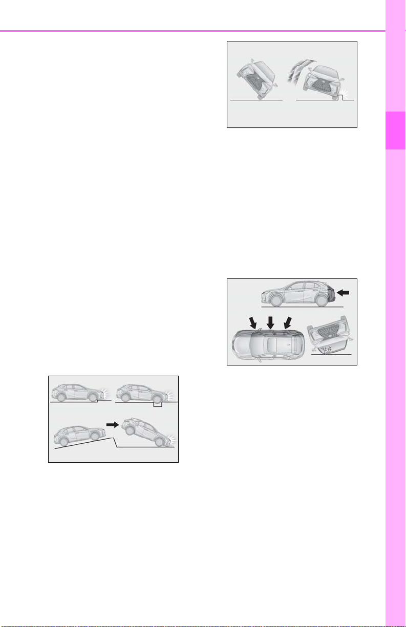
■ Conditions under which the SRS air-
bags may deploy (inflate), other than a
collision
The SRS front airbags and SRS curtain
shield airbags may also deploy if a serious
impact occurs to the underside of your
vehicle. Some examples are shown in the
illustration.
● Hitting a curb, edge of pavement or hard
surface
● Falling into or jumping over a deep hole
● Landing hard or falling
The SRS curtain shield airbags may also
deploy under the situations shown in the
illustration.
● The angle of vehicle tip-up is marginal.
● The vehicle skids and hits a curb stone.
1-1. For safe use
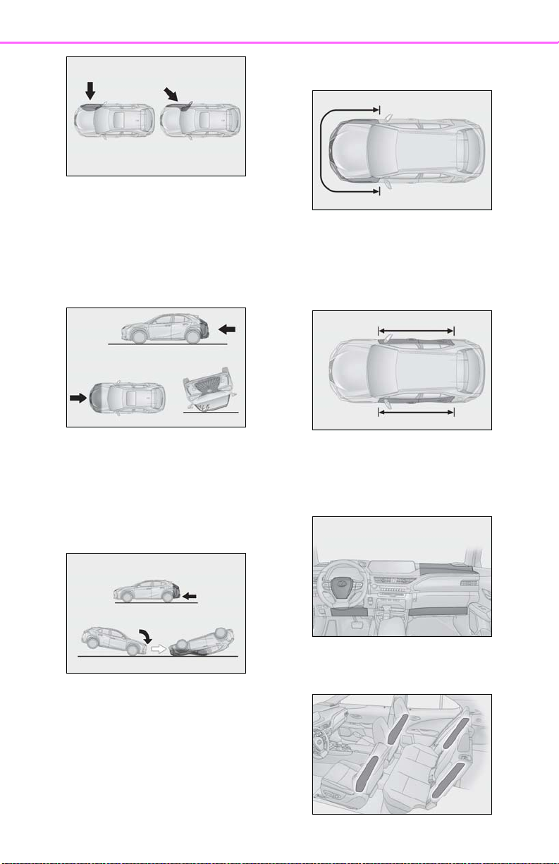
■ Types of collisions that may not deploy
33
the SRS airbags (SRS front airbags)
The SRS front airbags do not generally
inflate if the vehicle is involved in a side or
rear collision, if it rolls over, or if it is involved
in a low-speed frontal collision. But, whenever a collision of any type causes sufficient
forward deceleration of the vehicle, deployment of the SRS front airbags may occur.
● Collision from the side
● Collision from the rear
● Vehicle rollover
■ Types of collisions that may not deploy
the SRS airbags (SRS side and curtain
shield airbags)
The SRS side and curtain shield airbags
may not activate if the vehicle is subjected
to a collision from the side at certain angles,
or a collision to the side of the vehicle body
other than the passenger compartment.
● Collision from the side to the vehicle
body other than the passenger compartment
● Collision from the side at an angle
1
For safety and security
Page 34
34
1-1. For safe use
The SRS side airbags do not generally
inflate if the vehicle is involved in a frontal or
rear collision, if it rolls over, or if it is involved
in a low-speed side collision.
● Collision from the front
● Collision from the rear
● Vehicle rollover
that was not severe enough to cause the
SRS front airbags to inflate.
● A portion of a door or its surrounding
area is damaged, deformed or has had a
hole made in it, or the vehicle was
involved in an accident that was not
severe enough to cause the SRS side and
curtain shield airbags to inflate.
The SRS curtain shield airbags do not generally inflate if the vehicle is involved in a
rear collision, if it pitches end over end, or if
it is involved in a low-speed side or lowspeed frontal collision.
● Collision from the rear
● Pitching end over end
■ When to contact your Lexus dealer
In the following cases, the vehicle will
require inspection and/or repair. Contact
your Lexus dealer as soon as possible.
● Any of the SRS airbags have been
inflated.
● The front of the vehicle is damaged or
deformed, or was involved in an accident
● The pad section of the steering wheel,
dashboard near the front passenger airbag or lower portion of the instrument
panel is scratched, cracked, or otherwise
damaged.
● The surface of the seats with the SRS side
airbag is scratched, cracked, or otherwise damaged.
Page 35

1-1. For safe use
WARNING
35
● The portion of the front pillars, rear pillars
or roof side rail garnishes (padding) containing the SRS curtain shield airbags
inside is scratched, cracked, or otherwise
damaged.
■ SRS airbag precautions
Observe the following precautions
regarding the SRS airbags.
Failure to do so may cause death or serious injury.
● The driver and all passengers in the
vehicle must wear their seat belts
properly.
The SRS airbags are supplemental
devices to be used with the seat belts.
● The SRS driver airbag deploys with
considerable force, and can cause
death or serious injury especially if the
driver is very close to the airbag. The
National Highway Traffic Safety
Administration (NHTSA) advises:
Since the risk zone for the driver’s airbag is the first 2 - 3 in. (50 - 75 mm) of
inflation, placing yourself 10 in. (250
mm) from your driver airbag provides
you with a clear margin of safety. This
distance is measured from the center
of the steering wheel to your breastbone. If you sit less than 10 in. (250
mm) away now, you can change your
driving position in several ways:
• Move your seat to the rear as far as
you can while still reaching the pedals
comfortably.
• Slightly recline the back of the seat.
Although vehicle designs vary, many
drivers can achieve the 10 in. (250
mm) distance, even with the driver seat
all the way forward, simply by reclining
the back of the seat somewhat. If
reclining the back of your seat makes it
hard to see the road, raise yourself by
using a firm, non-slippery cushion, or
raise the seat if your vehicle has that
feature.
• If your steering wheel is adjustable, tilt
it downward. This points the airbag
toward your chest instead of your head
and neck.
1
For safety and security
The seat should be adjusted as recommended by NHTSA above, while still
maintaining control of the foot pedals,
steering wheel, and your view of the
instrument panel controls.
Page 36
36
WARNING
● If the seat belt extender has been con-
1-1. For safe use
nected to the front seat belt buckles
but the seat belt extender has not also
been fastened to the latch plate of the
seat belt, the SRS front airbags will
judge that the driver and front passenger are wearing the seat belt even
though the seat belt has not been connected. In this case, the SRS front airbags may not activate correctly in a
collision, resulting in death or serious
injury in the event of a collision. Be
sure to wear the seat belt with the seat
belt extender.
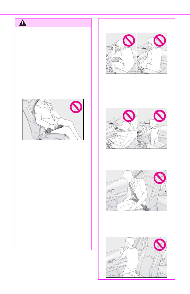
● The SRS front passenger airbag also
deploys with considerable force, and
can cause death or serious injury
especially if the front passenger is very
close to the airbag. The front passenger seat should be as far from the airbag as possible with the seatback
adjusted, so the front passenger sits
upright.
● Do not sit on the edge of the seat or
lean against the dashboard.
● Do not allow a child to stand in front of
the SRS front passenger airbag unit or
sit on the knees of a front passenger.
● Do not allow the front seat occupants
to hold items on their knees.
● Do not lean against the door, the roof
side rail or the front, side and rear pillars.
● Improperly seated and/or restrained
infants and children can be killed or
seriously injured by a deploying airbag.
An infant or child who is too small to
use a seat belt should be properly
secured using a child restraint system.
Lexus strongly recommends that all
infants and children be placed in the
rear seats of the vehicle and properly
restrained. The rear seats are safer for
infants and children than the front passenger seat. (P.44)
● Do not allow anyone to kneel on the
passenger seats toward the door or
put their head or hands outside the
vehicle.
Page 37
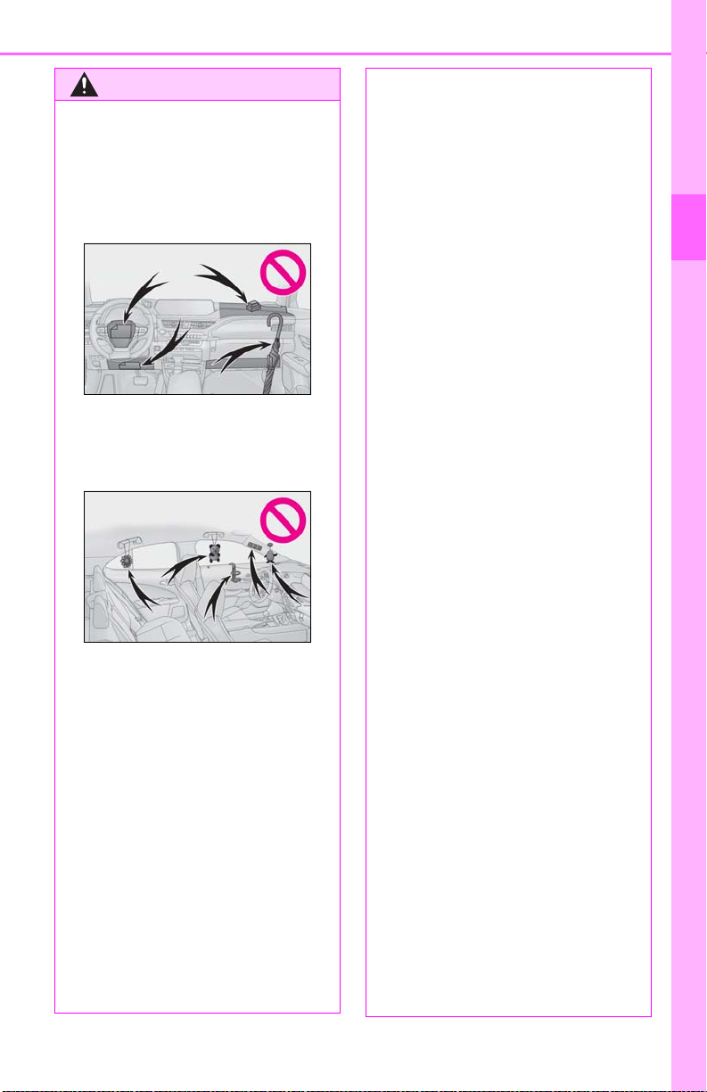
WARNING
● Do not attach anything to or lean any-
thing against areas such as the dashboard, steering wheel pad and lower
portion of the instrument panel.
These items can become projectiles
when the SRS driver, front passenger
and knee airbags deploy.
● Do not attach anything to areas such
as a door, windshield, side door glass,
front or rear pillar, roof side rail and
assist grip.
1-1. For safe use
● Do not strike or apply significant levels
of force to the area of the SRS airbag
components or the front doors.
Doing so can cause the SRS airbags to
malfunction.
● Do not touch any of the component
parts immediately after the SRS airbags have deployed (inflated) as they
may be hot.
● If breathing becomes difficult after the
SRS airbags have deployed, open a
door or window to allow fresh air in, or
leave the vehicle if it is safe to do so.
Wash off any residue as soon as possible to prevent skin irritation.
● If the areas where the SRS airbags are
stored, such as the steering wheel pad
and front and rear pillar garnishes, are
damaged or cracked, have them
replaced by your Lexus dealer.
● Do not place anything, such as a cush-
ion, on the front passenger’s seat.
Doing so will disperse the passenger’s
weight, which prevents the sensor
from detecting the passenger’s weight
properly. As a result, the SRS front airbags for the front passenger may not
deploy in the event of a collision.
37
1
For safety and security
● Do not hang coat hangers or other
hard objects on the coat hooks. All of
these items could become projectiles
and may cause death or serious injury,
should the SRS curtain shield airbags
deploy.
● If a vinyl cover is put on the area where
the SRS knee airbag will deploy, be
sure to remove it.
● Do not use seat accessories which
cover the parts where the SRS side airbags inflate as they may interfere with
inflation of the SRS airbags. Such
accessories may prevent the side airbags from activating correctly, disable
the system or cause the side airbags to
inflate accidentally, resulting in death
or serious injury.
■ Modification and disposal of SRS air-
bag system components
Do not dispose of your vehicle or perform any of the following modifications
without consulting your Lexus dealer.
The SRS airbags may malfunction or
deploy (inflate) accidentally, causing
death or serious injury.
● Installation, removal, disassembly and
repair of the SRS airbags
● Repairs, modifications, removal or
replacement of the steering wheel,
instrument panel, dashboard, seats or
seat upholstery, front, side and rear pillars, roof side rails, front door panels,
front door trims or front door speakers
● Modifications to the front door panel
(such as making a hole in it)
Page 38

38
WARNING
● Repairs or modifications of the front
1-1. For safe use
fender, front bumper, or side of the
occupant compartment
● Installation of a grille guard (bull bars,
kangaroo bar, etc.), snow plows,
winches or roof luggage carrier
● Modifications to the vehicle’s suspen-
sion system
● Installation of electronic devices such
as mobile two-way radios and CD
players
● Modifications to your vehicle for a per-
son with a physical disability
Page 39
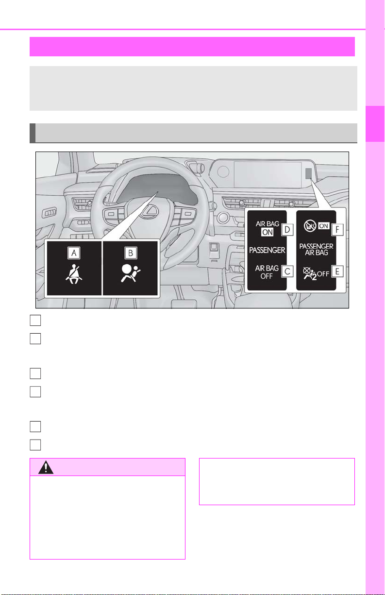
1-1. For safe use
A
B
C
D
E
F
WARNING
Front passenger occupant classification system
Your vehicle is equipped with a front passenger occupant classification system.
This system detects the conditions of the front passenger seat and activates or
deactivates the front passenger airbag and front passenger knee airbag.
39
System components
Front passenger’s seat belt reminder light
SRS warning light
For the U.S.A.
“AIR BAG OFF” indicator light
“AIR BAG ON” indicator light
1
For safety and security
For Canada
“AIR BAG OFF” indicator light
“AIR BAG ON” indicator light
■ Front passenger occupant classifica-
tion system precautions
Observe the following precautions
regarding the front passenger occupant
classification system. Failure to do so may
cause death or serious injury.
● Wear the seat belt properly.
● Make sure the front passenger’s seat
belt plate has not been left inserted
into the buckle before someone sits in
the front passenger seat.
Page 40

40
WARNING
● Make sure the “AIR BAG OFF” indica-
1-1. For safe use
tor light is not illuminated when using
the seat belt extender for the front passenger seat. If the “AIR BAG OFF”
indicator light is illuminated, disconnect the extender tongue from the seat
belt buckle, and reconnect the seat
belt. Reconnect the seat belt extender
after making sure the “AIR BAG ON”
indicator light is illuminated. If you use
the seat belt extender while the “AIR
BAG OFF” indicator light is illuminated, the SRS airbags for the front
passenger will not activate, which
could cause death or serious injury in
the event of a collision.
● Do not apply a heavy load to the front
passenger seat or equipment (e.g.
seatback pocket or armrest).
● If an adult sits in the front passenger
seat, the “AIR BAG ON” indicator light
is illuminated. If the “AIR BAG OFF”
indicator is illuminated, ask the passenger to sit up straight, well back in the
seat, feet on the floor, and with the seat
belt worn correctly. If the “AIR BAG
OFF” indicator still remains illuminated, either ask the passenger to
move to the rear seat, or if that is not
possible, move the front passenger
seat fully rearward.
● When it is unavoidable to install a for-
ward-facing child restraint system on
the front passenger seat, install the
child restraint system on the front passenger seat in the proper order.
(P.47)
● Do not modify or remove the front
seats.
● Do not put weight on the front passen-
ger seat by putting your hands or feet
on the front passenger seat seatback
from the rear passenger seat.
● Do not let a rear passenger lift the
front passenger seat with their feet or
press on the seatback with their legs.
● Do not put objects under the front pas-
senger seat.
● Do not recline the front passenger
seatback so far that it touches a rear
seat. This may cause the “AIR BAG
OFF” indicator light to be illuminated,
which indicates that the SRS airbags
for the front passenger will not activate
in the event of a severe accident. If the
seatback touches the rear seat, return
the seatback to a position where it
does not touch the rear seat. Keep the
front passenger seatback as upright as
possible when the vehicle is moving.
Reclining the seatback excessively
may lessen the effectiveness of the
seat belt system.
● Do not kick the front passenger seat or
subject it to severe impact. Otherwise,
the SRS warning light may come on to
indicate a malfunction of the front passenger occupant classification system.
In this case, contact your Lexus dealer
immediately.
● Child restraint systems installed on the
rear seat should not contact the front
seatbacks.
● Do not use a seat accessory, such as a
cushion and seat cover, that covers the
seat cushion surface.
● Do not modify or replace the uphol-
stery of the front seat.
Page 41

1-1. For safe use
Condition and operation in the front passenger occupant classification
system
41
■ Adult
*1
“AIR BAG ON” and “AIR BAG OFF” indica-
Indicator/warning
light
SRS warning light Off
Front passenger’s seat belt reminder light
Front passenger airbag
Devices
Front passenger knee airbag
■ Child
*4
“AIR BAG ON” and “AIR BAG OFF” indica-
Indicator/warning
light
SRS warning light Off
Front passenger’s seat belt reminder light
Front passenger airbag
Devices
Front passenger knee airbag
■ Child restraint system with infant
tor lights
tor lights
*5
“AIR BAG ON”
Off*2 or flashing
*3
Activated
“AIR BAG OFF” or
“AIR BAG ON”
Off*2 or flashing
*4
*3
Deactivated or acti-
*4
vated
1
For safety and security
Indicator/warning
light
Devices
■ Unoccupied
Indicator/warning
light
“AIR BAG ON” and “AIR BAG OFF” indica-
tor lights
SRS warning light Off
Front passenger’s seat belt reminder light
Front passenger airbag
Front passenger knee airbag
“AIR BAG ON” and “AIR BAG OFF” indica-
tor lights
SRS warning light
Front passenger’s seat belt reminder light
“AIR BAG OFF”
Off*2 or flashing
Deactivated
“AIR BAG OFF”
Off
*6
*3
Page 42

42
1-1. For safe use
Devices
Deactivated
Front passenger knee airbag
Front passenger airbag
■ There is a malfunction in the system
Indicator/warning
light
“AIR BAG ON” and “AIR BAG OFF” indica-
tor lights
SRS warning light
“AIR BAG OFF”
On
Front passenger’s seat belt reminder light
Front passenger airbag
Devices
Deactivated
Front passenger knee airbag
*1
: The system judges a person of adult size as an adult. When a smaller adult sits in the
front passenger seat, the system may not recognize him/her as an adult depending on
his/her physique and posture.
*2
: In the event the front passenger is wearing a seat belt.
*3
: In the event the front passenger does not wear a seat belt.
*4
: For some children, child in seat, child in booster seat or child in convertible seat, the sys-
tem may not recognize him/her as a child. Factors which may affect this can be the physique or posture.
*5
: Never install a rear-facing child restraint system on the front passenger seat. A forward-
facing child restraint system should only be installed on the front passenger seat when it
is unavoidable. (P.47)
*6
: In case the indicator light is not illuminated, consult this manual on how to install the child
restraint system properly. (P.44)
Page 43

1-1. For safe use
WARNING
43
Exhaust gas precautions
Harmful substances to the human
body are contained in exhaust
gases if inhaled.
Exhaust gases contain harmful carbon
monoxide (CO), which is colorless and
odorless. Observe the following precautions.
Failure to do so may cause exhaust gases
to enter the vehicle and may lead to an
accident caused by light-deadness, or
may lead to death or a serious health
hazard.
■ Important points while driving
● Keep the back door closed.
● If you smell exhaust gases in the vehi-
cle even when the back door is closed,
open the windows and have the vehicle inspected at your Lexus dealer as
soon as possible.
■ When parking
● If the vehicle is in a poorly ventilated
area or a closed area, such as a
garage, stop the engine.
■ Exhaust pipe
The exhaust system needs to be checked
periodically. If there is a hole or crack
caused by corrosion, damage to a joint
or abnormal exhaust noise, be sure to
have the vehicle inspected and repaired
by your Lexus dealer.
1
For safety and security
● Do not leave the vehicle with the
engine running for a long time. If such
a situation cannot be avoided, park the
vehicle in an open space and ensure
that exhaust fumes do not enter the
vehicle interior.
● Do not leave the engine running in an
area with snow build-up, or where it is
snowing. If snowbanks build up around
the vehicle while the engine is running,
exhaust gases may collect and enter
the vehicle.
Page 44

44
WARNING
1-2.Child safety
1-2. Child safety
Riding with children
Child restraint systems
Observe the following precautions
when children are in the vehicle.
Use a child restraint system appropriate for the child, until the child
becomes large enough to properly
wear the vehicle’s seat belt.
It is recommended that children
sit in the rear seats to avoid accidental contact with the shift lever,
wiper switch, etc.
Use the rear door child-protector
lock or the window lock switch to
avoid children opening the door
while driving or operating the
power window accidentally.
(P.99, 134)
Do not let small children operate
equipment which may catch or
pinch body parts, such as the
power window, hood, back door,
seats, etc.
Before installing a child restraint
system in the vehicle, there are precautions that need to be observed,
different types of child restraint systems, as well as installation methods, etc., written in this manual.
Use a child restraint system when
riding with a small child that cannot
properly use a seat belt. For the
child’s safety, install the child restraint
system to a rear seat. Be sure to follow the installation method that is in
the operation manual enclosed with
the restraint system.
Table of contents
Points to remember: P.44
Child restraint system: P.46
When using a child restraint system on
a passenger seat: P.47
■ When children are in the vehicle
Never leave children unattended in the
vehicle, and never allow children to have
or use the key.
Children may be able to start the vehicle
or shift the vehicle into neutral. There is
also a danger that children may injure
themselves by playing with the windows,
the moon roof (if equipped) or other features of the vehicle. In addition, heat
build-up or extremely cold temperatures
inside the vehicle can be fatal to children.
When using a child restraint system on
a rear seat: P.48
Child restraint system installation
method
• Fixed with a seat belt: P.48
• Fixed with a child restraint LATCH
anchor: P.52
• Using an anchor bracket (for top
tether strap): P.54
Points to remember
The laws of all 50 states of the U.S.A.
as well as Canada now require the use
of child restraint systems.
Page 45

1-2. Child safety
WARNING
45
Prioritize and observe the warn-
ings, as well as the laws and regulations for child restraint systems.
Use a child restraint system until the
child becomes large enough to
properly wear the vehicle’s seat belt.
Choose a child restraint system that
suits your vehicle and is appropriate
to the age and size of the child.
■ When a child is riding
Observe the following precautions. Failure to do so may result in death or serious injury.
● For effective protection in automobile
accidents and sudden stops, a child
must be properly restrained, using a
seat belt or child restraint system
which is correctly installed. For installation details, refer to the operation manual enclosed with the child restraint
system. General installation instruction
is provided in this manual.
● Lexus strongly urges the use of a
proper child restraint system that conforms to the weight and size of the
child, installed on the rear seat.
According to accident statistics, the
child is safer when properly restrained
in the rear seat than in the front seat.
■ Handling the child restraint system
If the child restraint system is not properly fixed in place, the child or other passengers may be seriously injured or even
killed in the event of sudden braking, sudden swerving, or an accident.
● If the vehicle were to receive a strong
impact from an accident, etc., it is possible that the child restraint system has
damage that is not readily visible. In
such cases, do not reuse the restraint
system.
● Make sure you have complied with all
installation instructions provided with
the child restraint system manufacturer and that the system is properly
secured.
● Keep the child restraint system prop-
erly secured on the seat even if it is not
in use. Do not store the child restraint
system unsecured in the passenger
compartment.
● If it is necessary to detach the child
restraint system, remove it from the
vehicle or store it securely in the luggage compartment.
1
For safety and security
● Holding a child in your or someone
else’s arms is not a substitute for a child
restraint system. In an accident, the
child can be crushed against the windshield or between the holder and the
interior of the vehicle.
Page 46
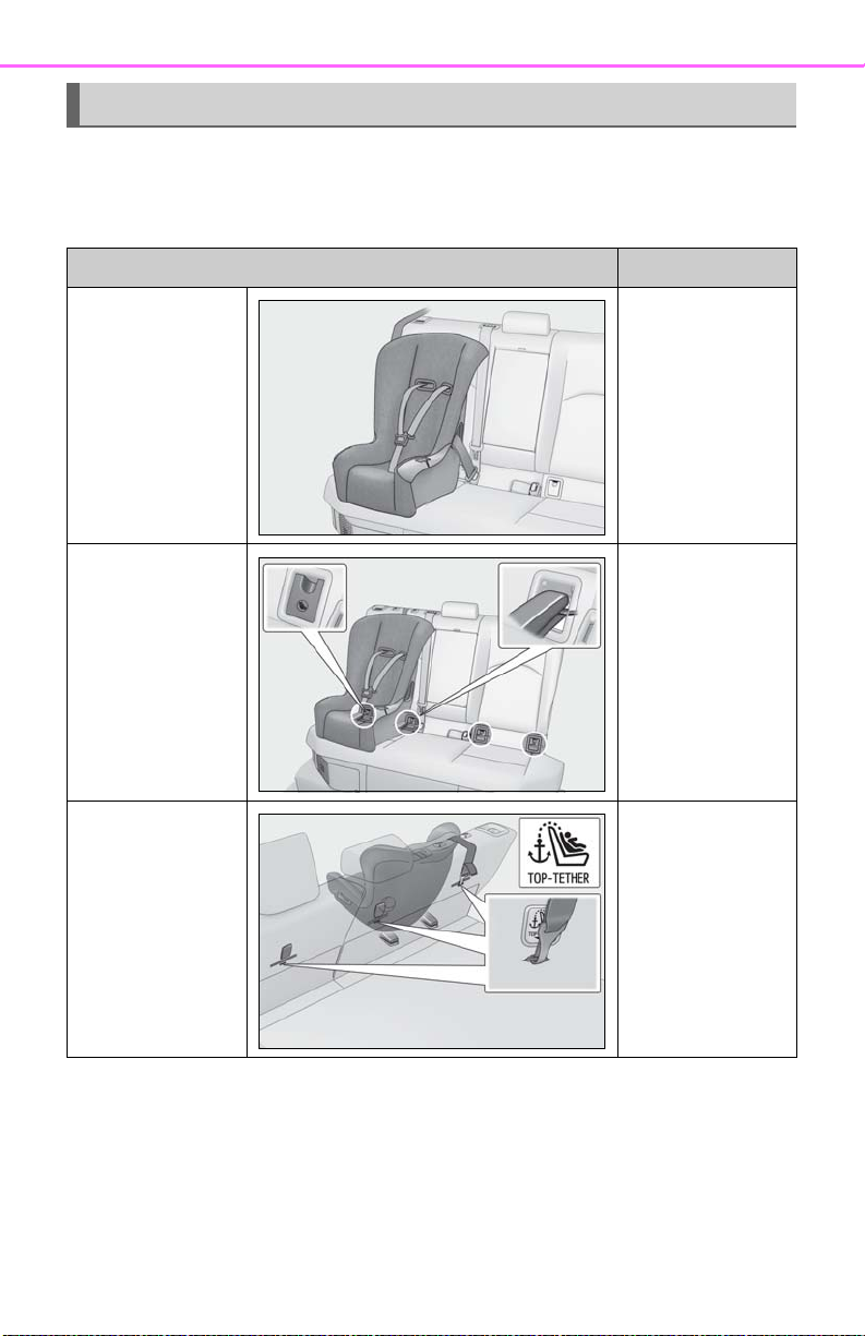
46
1-2. Child safety
Child restraint system
■ Types of child restraint system installation methods
Confirm with the operation manual enclosed with the child restraint system about
the installation of the child restraint system.
Installation method Page
Seat belt attachment P.48
Child restraint
LATCH anchors
attachment
P.52
Anchor brackets (for
top tether strap)
attachment
P.54
Page 47
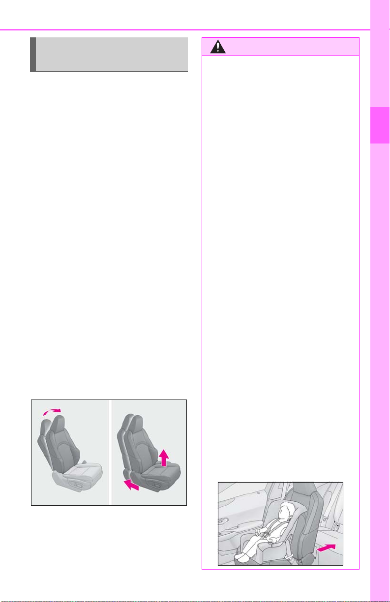
When using a child restraint sys-
WARNING
tem
■ When installing a child restraint
system to the front passenger seat
For the safety of a child, install child
restraint systems to a rear seats. When
installing child restraint system to the
front passenger seat is unavoidable,
adjust the passenger seat as follows
and install the child restraint system.
Raise the seatback as much as pos-
sible.
Move the seat to the rearmost posi-
tion.
Raise the seat to the upper most
position.
Adjust the front of the seat cushion
to the lowest position.
If the head restraint interferes with
the child restraint system installation and the head restraint can be
removed, remove the head restraint.
Otherwise, put the head restraint in
the upper most position.
1-2. Child safety
■ When installing a child restraint sys-
tem
Observe the following when installing
child restraint system to the front passenger seat if it is unavoidable. The front passenger SRS air bag inflates with
considerable speed and force that if not
observed may lead to death or serious
injury to the child.
● Never install a rear-facing child
restraint system on the front passenger
seat even if the “AIR BAG OFF” indicator light is illuminated. In the event of
an accident, the force of the rapid inflation of the front passenger airbag can
cause death or serious injury to the
child if the rear-facing child restraint
system is installed on the front passenger seat.
● A forward-facing child restraint system
may be installed on the front passenger seat only when it is unavoidable. A
child restraint system that requires a
top tether strap should not be used in
the front passenger seat since there is
no top tether strap anchor for the front
passenger seat.
● A forward-facing child restraint system
may be installed on the front passenger seat only when it is unavoidable.
When installing a forward-facing child
restraint system on the front passenger
seat, move the seat as far back as possible, and raise the seat to the upper
most position, even if the “AIR BAG
OFF” indicator light is illuminated. If
the head restraint interferes with the
child restraint system installation and
the head restraint can be removed,
remove the head restraint.
47
1
For safety and security
Page 48
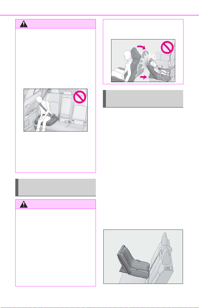
48
WARNING
WARNING
● Do not allow the child to lean his/her
● When a booster seat is installed,
1-2. Child safety
head or any part of his/her body
against the door or the area of the seat,
front pillars or roof side rails from
which the SRS side airbags or SRS
curtain shield airbags deploy even if
the child is seated in the child restraint
system. It is dangerous if the SRS side
and curtain shield airbags inflate, and
the impact could cause death or serious injury to the child.
always ensure that the shoulder belt is
positioned across the center of the
child’s shoulder. The belt should be
kept away from the child’s neck, but
not so that it could fall off the child’s
shoulder.
When using a child restraint system on a rear seat
■ When installing a child restraint sys-
tem
Observe the following precautions. Failure to do so may result in death or serious injury.
● Use child restraint system suitable to
the age and size of the child and install
it to the rear seat.
● Adjust the front passenger seat so that
it does not interfere with the child
restraint system.
Child restraint system fixed with
a seat belt
A child restraint system for a small
child or baby must itself be properly
restrained on the seat with the lap portion of the lap/shoulder belt.
■ Installing child restraint system
using a seat belt (child restraint
lock function belt)
Install the child restraint system in
accordance to the operation manual
enclosed with the child restraint system.
■ Rear-facing Infant seat/con-
vertible seat
1 Place the child restraint system on
the rear seat facing the rear of the
vehicle.
● If the driver’s seat interferes with the
child restraint system and prevents it
from being attached correctly, attach
the child restraint system to the righthand rear seat.
Page 49
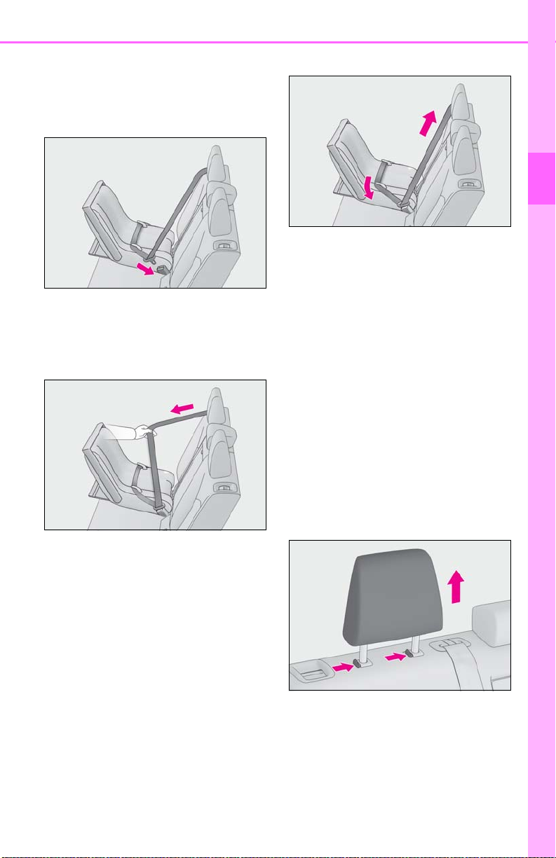
1-2. Child safety
49
2 Run the seat belt through the child
restraint system and insert the plate
into the buckle. Make sure that the
belt is not twisted.
3 Fully extend the shoulder belt and
allow it to retract to put it in lock
mode. In lock mode, the belt cannot
be extended.
extended.
1
For safety and security
5 After installing the child restraint
system, rock it back and forth to
ensure that it is installed securely.
■ Forward-facing Convertible
seat
1 Adjust the seat
When using the front passenger seat: If
installing the child restraint system to the
front passenger seat is unavoidable, refer
to P.47 for front passenger seat adjustment.
2 If the head restraint interferes with
the child restraint system installation and the head restraint can be
removed, remove the head
restraint.
4 While pushing the child restraint
system down into the rear seat,
allow the shoulder belt to retract
until the child restraint system is
securely in place.
After the shoulder belt has retracted to a
point where there is no slack in the belt,
pull the belt to check that it cannot be
Page 50
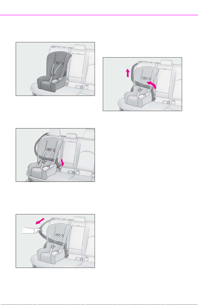
50
1-2. Child safety
3 Place the child restraint system on
the seat facing the front of the vehicle.
4 Run the seat belt through the child
restraint system and insert the plate
into the buckle. Make sure that the
belt is not twisted.
child restraint system is securely in
place.
After the shoulder belt has retracted to a
point where there is no slack in the belt,
pull the belt to check that it cannot be
extended.
7 If the child restraint has a top tether
strap, follow the child restraint manufacturer’s operation manual
regarding the installation, using the
top tether strap to latch onto the
top tether strap anchor. (P.54)
8 After installing the child restraint
system, rock it back and forth to
ensure that it is installed securely.
5 Fully extend the shoulder belt and
allow it to retract to put it in lock
mode. In lock mode, the belt cannot
be extended.
6 While pushing the child restraint
system into the rear seat, allow the
shoulder belt to retract until the
■ Booster seat
1 If installing the child restraint sys-
tem to the front passenger seat is
unavoidable, refer to P.47 for front
passenger seat adjustment.
2 High back type: If the head restraint
interferes with your child restraint
system, and the head restraint can
Page 51
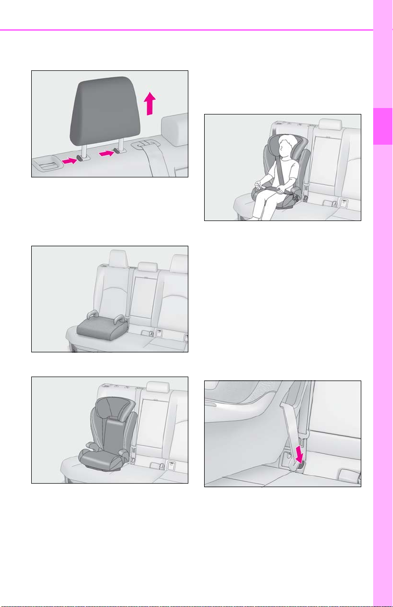
1-2. Child safety
51
be removed, remove the head
restraint.
3 Place the child restraint system on
the seat facing the front of the vehicle.
Booster type
High back type
Make sure that the belt is not
twisted.
Check that the shoulder belt is correctly
positioned over the child’s shoulder and
that the lap belt is as low as possible.
(P.27)
1
For safety and security
■ Removing a child restraint system
installed with a seat belt
Press the buckle release button and
fully retract the seat belt.
When releasing the buckle, the child
restraint system may spring up due to the
rebound of the seat cushion. Release the
buckle while holding down the child
restraint system.
Since the seat belt automatically reels itself,
slowly return it to the stowing position.
4 Sit the child in the child restraint
system. Fit the seat belt to the child
restraint system according to the
manufacturer’s instructions and
insert the plate into the buckle.
Page 52
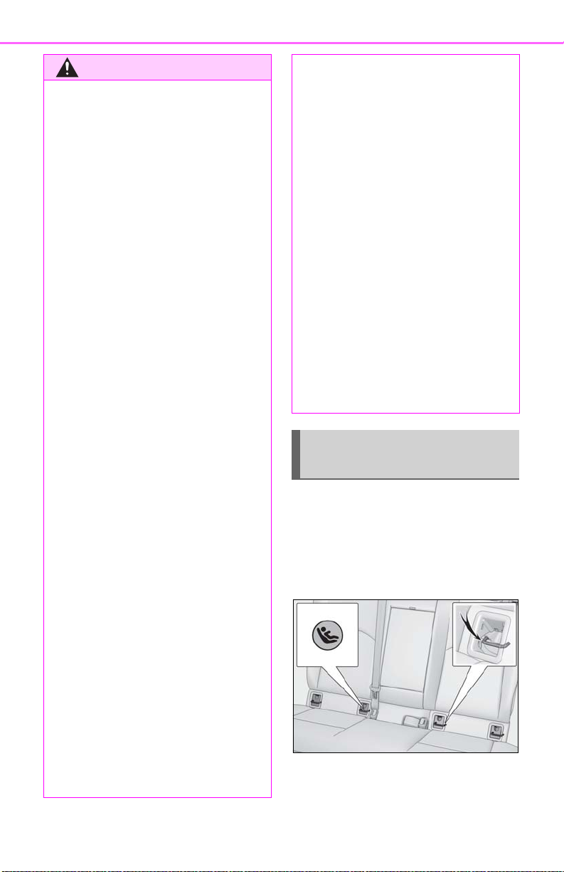
52
WARNING
■ When installing a child restraint sys-
Observe the following precautions. Failure to do so may result in death or serious injury.
● Do not allow children to play with the
● Ensure that the belt and plate are
● Shake the child restraint system left
● After securing a child restraint system,
● When a booster seat is installed,
● Follow all installation instructions pro-
1-2. Child safety
tem
seat belt. If the seat belt becomes
twisted around a child’s neck, it may
lead to choking or other serious injuries that could result in death. If this
occurs and the buckle cannot be
unfastened, scissors should be used to
cut the belt.
securely locked and the seat belt is not
twisted.
and right, and forward and backward
to ensure that it has been securely
installed.
never adjust the seat.
always ensure that the shoulder belt is
positioned across the center of the
child’s shoulder. The belt should be
kept away from the child’s neck, but
not so that it could fall off the child’s
shoulder.
vided by the child restraint system
manufacturer.
● When installing a child restraint system
in the rear center seat, adjust both
seatbacks at the same angle. Otherwise, the child restraint system cannot
be securely restrained and this may
cause death or serious injuries in the
event of sudden braking, sudden
swerving or an accident.
■ When installing a booster seat
To prevent the belt from going into ALR
lock mode, do not fully extend the shoulder belt. ALR mode causes the belt to
tighten only. This could cause injury or
discomfort to the child. (P.28)
■ Do not use a seat belt extender
If a seat belt extender is used when
installing a child restraint system, the seat
belt will not securely hold the child
restraint system, which could cause
death or serious injury to the child or
other passengers in the event of sudden
braking, sudden swerving or an accident.
Child restraint system fixed with
a child restraint LATCH anchor
■ Child restraint LATCH anchors
LATCH anchors are provided for the
outboard rear seats. (Marks displaying
the location of the anchors are
attached to the seats.)
● When securing some types of child
restraint systems in rear seats, it may
not be possible to properly use the
seat belts in positions next to the child
restraint without interfering with it or
affecting seat belt effectiveness. Be
sure your seat belt fits snugly across
your shoulder and low on your hips. If it
does not, or if it interferes with the
child restraint, move to a different position. Failure to do so may result in
death or serious injury.
■ When installing in the rear out-
board seats
Install the child restraint system in
Page 53
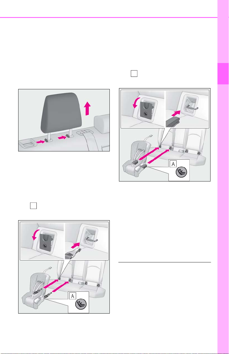
1-2. Child safety
A
A
53
accordance to the operation manual
enclosed with the child restraint system.
1 If the head restraint interferes with
the child restraint system installation and the head restraint can be
removed, remove the head
restraint.
With flexible lower attachments
2 Remove the anchorage covers, and
latch the hooks of the lower attachments onto the LATCH anchors.
For owners in Canada:
The symbol on a child restraint system indi-
cates the presence of a lower connector system.
With rigid lower attachments
2 Remove the anchorage covers, and
latch the buckles onto the LATCH
anchors.
For owners in Canada:
The symbol on a child restraint system indi-
cates the presence of a lower connector system.
3 If the child restraint has a top tether
strap, follow the child restraint manufacturer’s operation manual
regarding the installation, using the
top tether strap to latch onto the
top tether strap anchor. (P.54)
1
For safety and security
4 After installing the child restraint
system, rock it back and forth to
ensure that it is installed securely.
■ When installing in the rear center seat
There are no LATCH anchors behind the
rear center seat. However, the inboard
LATCH anchors of the outboard seats,
which are 15.5 in. (396 mm) apart, can be
used if the child restraint system manufacturer’s instructions permit use of those
anchors with the anchor spacing stated.
Child restraint systems with rigid lower
attachments cannot be installed in the center seat. This type of child restraint system
Page 54
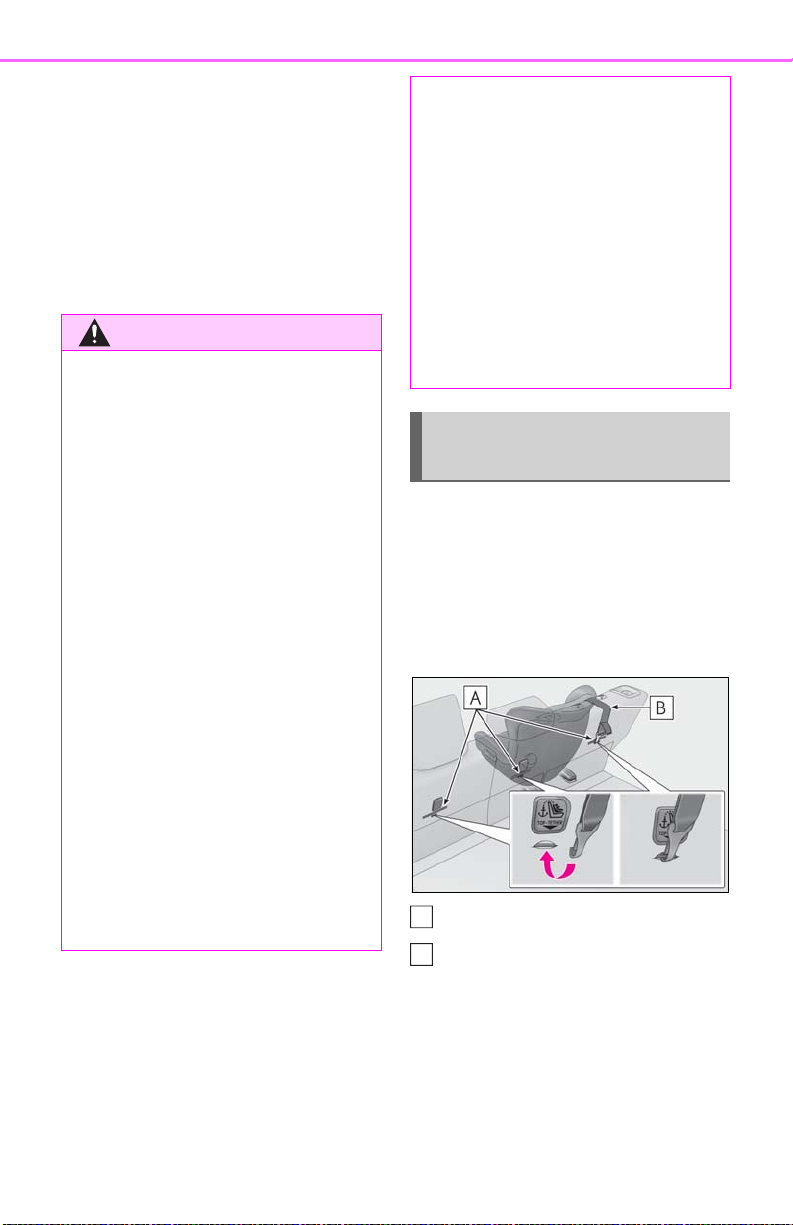
54
WARNING
A
B
1-2. Child safety
can only be installed in the outboard seat.
■ Laws and regulations pertaining to
anchors
The LATCH system conforms to
FMVSS225 or CMVSS210.2.
Child restraint systems conforming to
FMVSS213 or CMVSS213 specifications
can be used.
This vehicle is designed to conform to SAE
J1819.
■ When installing a child restraint sys-
tem
Observe the following precautions. Failure to do so may result in death or serious injury.
● Shake the child restraint system left
and right, and forward and backward
to ensure that it has been securely
installed.
● When using the LATCH anchors, be
sure that there are no foreign objects
around the anchors and that the seat
belt is not caught behind the child
restraint system.
● When securing some types of child
restraint systems in rear seats, it may
not be possible to properly use the
seat belts in positions next to the child
restraint without interfering with it or
affecting seat belt effectiveness. Be
sure your seat belt fits snugly across
your shoulder and low on your hips. If it
does not, or if it interferes with the
child restraint, move to a different position. Failure to do so may result in
death or serious injury.
● If the seat is adjusted, reconfirm the
security of the child restraint system.
Using an anchor bracket (for top
tether strap)
■ Anchor brackets (for top tether
strap)
Anchor brackets are provided for each
rear seat.
Use anchor brackets when fixing the
top tether strap.
● Follow all installation instructions pro-
vided by the child restraint system
manufacturer.
● Never attach two child restraint system
attachments to the same anchor. In a
collision, one anchor may not be
strong enough to hold two child
restraint system attachments and may
break. If the LATCH anchors are
already in use, use the seat belt to
install a child restraint system in the
center seat.
Anchor brackets
Top tether strap
■ Fixing the top tether strap to the
anchor bracket
Install the child restraint system in
accordance to the operation manual
enclosed with the child restraint system.
Page 55
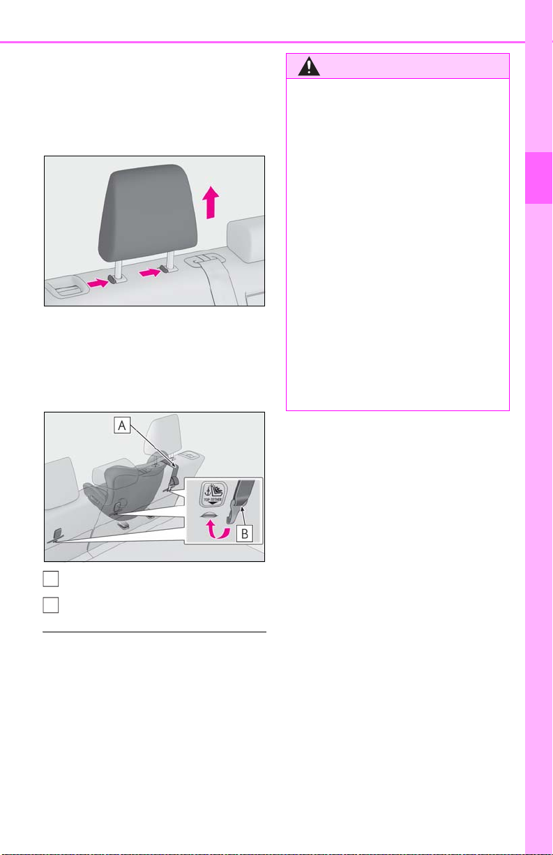
1 If the head restraint interferes with
A
B
WARNING
the child restraint system installation and the head restraint can be
removed, remove the head
restraint.
1-2. Child safety
■ When installing a child restraint sys-
tem
Observe the following precautions. Failure to do so may result in death or serious injury.
● Firmly attach the top tether strap and
make sure that the belt is not twisted.
55
1
2 Latch the hook onto the anchor
bracket and tighten the top tether
strap.
Make sure the top tether strap is securely
latched.
Top tether strap
Hook
● Do not attach the top tether strap to
anything other than the anchor
bracket.
● Shake the child restraint system left
and right, and forward and backward
to ensure that it has been securely
installed.
● After securing a child restraint system,
never adjust the seat.
● Follow all installation instructions pro-
vided by the child restraint system
manufacturer.
For safety and security
■ Laws and regulations pertaining to
anchors
The LATCH system conforms to
FMVSS225 or CMVSS210.2.
Child restraint systems conforming to
FMVSS213 or CMVSS213 specifications
can be used.
This vehicle is designed to conform to SAE
J1819.
Page 56

56
A
B
C
1-3.LEXUS Enform
1-3. LEXUS Enform
Lexus Enform Safety Con-
*
nect
*
:If equipped
Safety Connect is a subscriptionbased telematics service that uses
Global Positioning System (GPS)
data and embedded cellular technology to provide safety and security features to subscribers. Safety
Connect is supported by Lexus’
designated response center, which
operates 24 hours per day, 7 days
per week.
Safety Connect service is available
by subscription on select, telematics hardware-equipped vehicles.
By using the Safety Connect service, you are agreeing to be bound
by the Telematics Subscription Service Agreement and its Terms and
Conditions, as in effect and
amended from time to time, a current copy of which is available at
Lexus.com. All use of the Safety
Connect service is subject to such
then-applicable Terms and Conditions.
System components
Microphone
“SOS” button
LED light indicators
Page 57
■ Certification for Lexus Enform
1-3. LEXUS Enform
57
1
For safety and security
Services
Subscribers have the following Safety
Connect services available:
Automatic Collision Notification
Helps drivers receive necessary response
from emergency service providers.
P.59)
(
*
*
: U.S. Patent No. 7,508,298 B2
Stolen Vehicle Location
Helps drivers in the event of vehicle theft.
P.59)
(
Emergency Assistance Button
(“SOS”)
Connects drivers to response-center sup-
Page 58

58
1-3. LEXUS Enform
port. (P.59)
Enhanced Roadside Assistance
Provides drivers various on-road assistance. (
P.59)
Subscription
After you have signed the Telematics
Subscription Service Agreement and
are enrolled, you can begin receiving
services.
A variety of subscription terms is available for purchase. Contact your Lexus
dealer, call the following or push the
“SOS” button in your vehicle for further subscription details.
• The United States
1-800-25-LEXUS (1-800-255-3987)
• Canada
1-800-26-LEXUS (1-800-265-3987)
•Puerto Rico
1-877-539-8777
gency Assistance and Stolen Vehicle
Location will function in the United
States, including Hawaii and Alaska,
Puerto Rico and in Canada, and
Enhanced Roadside Assistance will function in the United States, Puerto Rico and
in Canada.
● Automatic Collision Notification, Emer-
gency Assistance, Stolen Vehicle and
Enhanced Road Assistance will not function in the United States Virgin Islands.
For vehicles first sold in the USVI, no
Safety Connect services will function in
and outside the United States Virgin
Islands.
● Safety Connect services are not subject
to section 255 of the Telecommunications Act and the device is not TTY compatible.
■ Languages
The Safety Connect response center will
offer support in multiple languages. The
Safety Connect system will offer voice
prompts in English, Spanish, and French.
Please indicate your language of choice
when enrolling.
■ When contacting the response center
You may be unable to contact the response
center if the network is busy.
■ Safety Connect Services Information
● Phone calls using the vehicle’s
Bluetooth
ble during Safety Connect.
● Safety Connect is available beginning Fall
2009 on select Lexus models (in the
contiguous United States only). Contact
with the Safety Connect response center
is dependent upon the telematics device
being in operative condition, cellular connection availability, and GPS satellite signal reception, which can limit the ability to
reach the response center or receive
emergency service support. Enrollment
and Telematics Subscription Service
Agreement required. A variety of subscription terms is available; charges vary
by subscription term selected and location.
● Automatic Collision Notification, Emer-
®
technology will not be possi-
Safety Connect LED light Indicators
When the engine switch is turned to
ON, the red indicator light comes on
for 2 seconds then turns off. Afterward,
the green indicator light comes on,
indicating that the service is active.
The following indicator light patterns
indicate specific system usage conditions:
Green indicator light on = Active
service
Green indicator light flashing =
Safety Connect call in process
Page 59

1-3. LEXUS Enform
59
Red indicator light (except at vehi-
cle start-up) = System malfunction
(contact your Lexus dealer)
No indicator light (off) = Safety
Connect service not active
Safety Connect services
■ Automatic Collision Notification
In case of either airbag deployment or
severe rear-end collision, the system is
designed to automatically call the
response center. The responding agent
receives the vehicle’s location and
attempts to speak with the vehicle
occupants to assess the level of emergency. If the occupants are unable to
communicate, the agent automatically
treats the call as an emergency, contacts the nearest emergency services
provider to describe the situation, and
requests that assistance be sent to the
location.
■ Stolen Vehicle Location
If your vehicle is stolen, Safety Connect
can work with local authorities to assist
them in locating and recovering the
vehicle. After filing a police report, call
the Safety Connect response center at
1-800-25-LEXUS (1-800-255-
3987) in the United States, 1-877539-8777 in Puerto Rico or 1-800265-3987 in Canada, and follow the
prompts for Safety Connect to initiate
this service.
In addition to assisting law enforcement with recovery of a stolen vehicle,
Safety-Connect-equipped vehicle
location data may, under certain cir-
cumstances, be shared with third parties to locate your vehicle. Further
information is available at Lexus.com.
■ Emergency Assistance Button
(“SOS”)
In the event of an emergency on the
road, push the “SOS” button to reach
the Safety Connect response center.
The answering agent will determine
your vehicle’s location, assess the
emergency, and dispatch the necessary assistance required.
If you accidentally press the “SOS” button,
tell the response-center agent that you are
not experiencing an emergency.
■ Enhanced Roadside Assistance
Enhanced Roadside Assistance adds
GPS data to the already included warranty-based Lexus roadside service.
Subscribers can press the “SOS” button to reach a Safety Connect
response-center agent, who can help
with a wide range of needs, such as:
towing, flat tire, fuel delivery, etc. For a
description of the Roadside Assistance
services and their limitations, please
see the Safety Connect Terms and
Conditions, which are available at
Lexus.com.
Safety information for Safety
Connect
Important! Read this information about
exposure to radio frequency signals
before using Safety Connect;
The Safety Connect system installed in
your vehicle is a low-power radio trans-
1
For safety and security
Page 60

60
mitter and receiver. It receives and also
sends out radio frequency (RF) signals.
In August 1996, the Federal Communications Commission (FCC) adopted
RF exposure guidelines with safety levels for mobile wireless phones. Those
guidelines are consistent with the
safety standards previously set by the
following U.S. and international standards bodies.
ANSI (American National Stan-
NCRP (National Council on Radia-
ICNIRP (International Commission
Those standards were based on comprehensive and periodic evaluations of
the relevant scientific literature. Over
120 scientists, engineers, and physicians from universities, and government health agencies and industries
reviewed the available body of
research to develop the ANSI Standard (C95.1).
1-3. LEXUS Enform
dards Institute) C95.1 [1992]
tion Protection and Measurement)
Report 86 [1986]
on Non-Ionizing Radiation Protection) [1996]
The design of Safety Connect complies with the FCC guidelines in addition to those standards.
Page 61
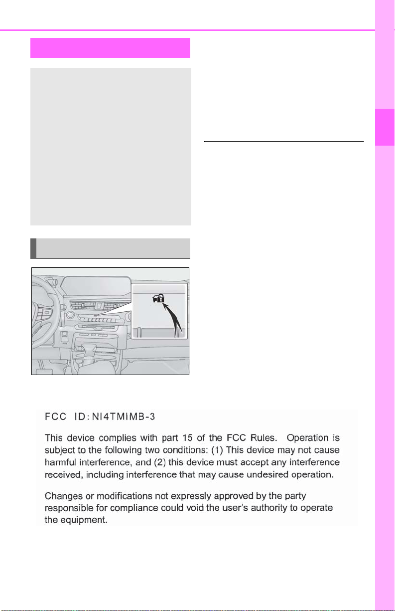
1-4.Theft deterrent system
Engine immobilizer system
The vehicle’s keys have built-in transponder chips that prevent the
engine from starting if a key has not
been previously registered in the
vehicle’s on-board computer.
Never leave the keys inside the
vehicle when you leave the vehicle.
This system is designed to help prevent vehicle theft but does not guarantee absolute security against all
vehicle thefts.
Operating the system
1-4. Theft deterrent system
The security indicator flashes after the
engine switch has been turned off to
indicate that the system is operating.
The indicator light stops flashing after
the engine switch has been turned to
ACC or ON to indicate that the system has been canceled.
■ System maintenance
The vehicle has a maintenance-free type
engine immobilizer system.
■ Conditions that may caus e the system to
malfunction
● If the grip portion of the key is in contact
with a metallic object
● If the key is in close proximity to or touch-
ing a key registered to the security system (key with a built-in transponder chip)
of another vehicle
61
1
For safety and security
■ Certification for the engine immobilizer system
For vehicles sold in the U.S.A., Hawaii, Guam and Puerto Rico
Page 62
62
NOTICE
For vehicles sold in Canada
■ To ensure the system operates cor-
1-4. Theft deterrent system
rectly
Do not modify or remove the system. If
modified or removed, the proper operation of the system cannot be guaranteed.
Page 63
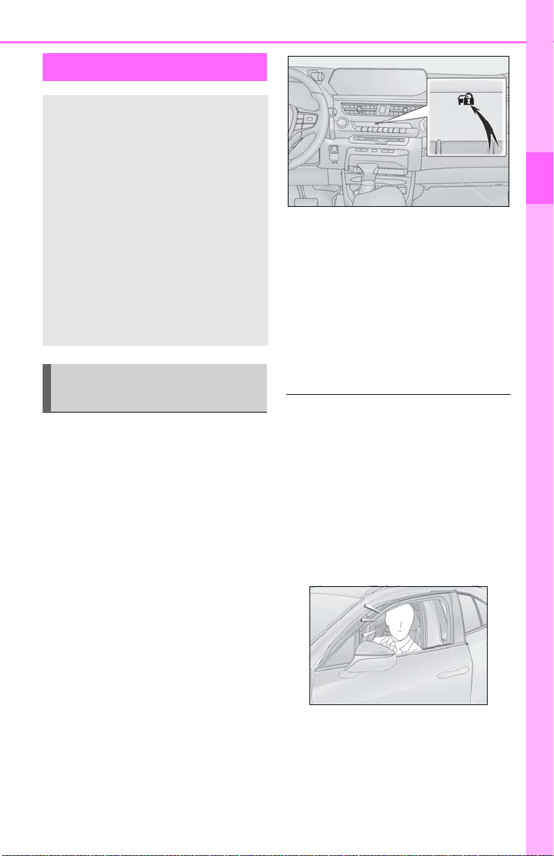
Alarm
The alarm uses light and sound to
give an alert when an intrusion is
detected.
1-4. Theft deterrent system
63
The alarm is triggered in the following situations when the alarm is set:
A locked door is unlocked or
opened in any way other than
using the entry function, wireless
remote control or mechanical
key. (The doors will lock again
automatically.)
The hood is opened.
Setting/canceling/stopping the
alarm system
■ Items to check before locking the
vehicle
To prevent unexpected triggering of
the alarm and vehicle theft, make sure
of the following:
Nobody is in the vehicle.
The windows and moon roof (if
equipped) are closed before the
alarm is set.
1
For safety and security
■ Canceling or stopping
Do one of the following to deactivate
or stop the alarms:
Unlock the doors.
Turn the engine switch to ACC or
ON, or start the engine. (The alarm
will be deactivated or stopped after
a few seconds.)
■ System maintenance
The vehicle has a maintenance-free type
alarm system.
■ Triggering of the alarm
The alarm may be triggered in the following
situations:
(Stopping the alarm deactivates the alarm
system.)
● A person inside the vehicle opens a door
or hood, or unlocks the vehicle using an
inside lock button.
No valuables or other personal
items are left in the vehicle.
■ Setting
Close the doors and hood, and lock all
the doors. The system will be set automatically after 30 seconds.
The security indicator changes from being
on to flashing when the system is set.
● The battery is recharged or replaced
when the vehicle is locked. (P.384)
Page 64
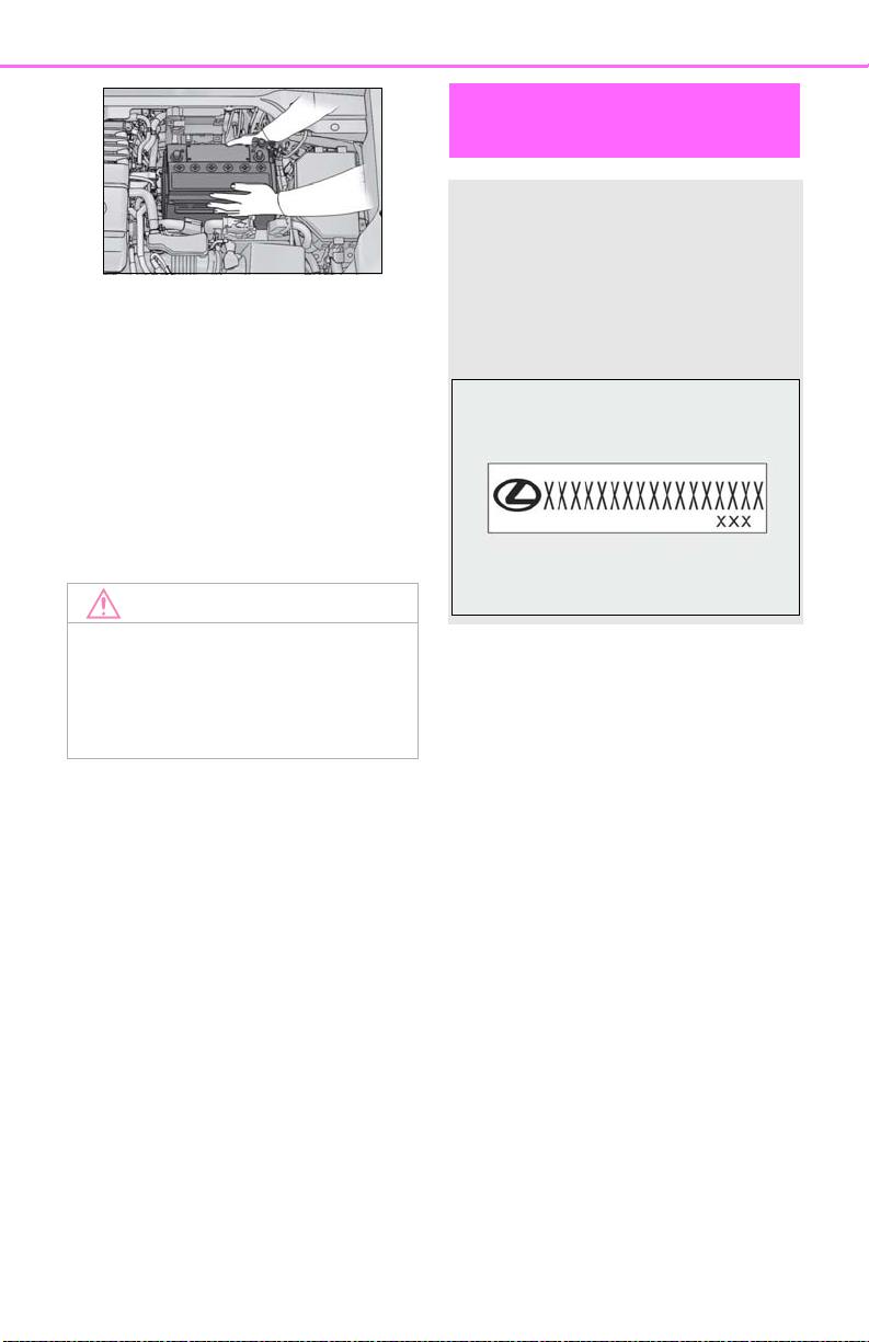
64
NOTICE
■ Alarm-operated door lock
In the following cases, depending on the situation, the door may automatically lock to
prevent improper entry into the vehicle:
● When a person remaining in the vehicle
unlocks the door and the alarm is activated.
● While the alarm is activated, a person
remaining in the vehicle unlocks the door.
● When recharging or replacing the bat-
tery.
■ To ensure the system operates cor-
Do not modify or remove the system. If
modified or removed, the proper operation of the system cannot be guaranteed.
1-4. Theft deterrent system
rectly
Theft prevention labels (for
the U.S.A.)
These labels are attached to the
vehicle to reduce vehicle theft by
facilitating the tracing and recovery of parts from stolen vehicles.
Do not remove under penalty of
law.
Page 65

65
Vehicle status information
and indicators
2-1. Instrument cluster
Warning lights and indicators. 66
Gauges and meters (except F
SPORT models) ........................ 70
Gauges and meters (F SPORT
models).......................................... 73
Multi-information display.......... 77
Head-up display ........................... 84
Fuel consumption information 88
2
2
Vehicle status information and indicators
Page 66
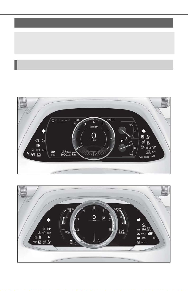
66
2-1.Instrument cluster
2-1. Instrument cluster
Warning lights and indicators
The warning lights and indicators on the instrument cluster, center panel and
outside rear view mirrors inform the driver of the status of the vehicle’s various
systems.
Warning lights and indicators displayed on the instrument cluster
For the purpose of explanation, the following illustrations display all warning lights
and indicators illuminated.
Except F SPORT models
F SPORT models
The location of warning lights and indicators may differ depending on the main
meter position.
Page 67
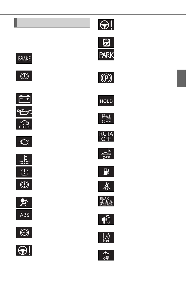
2-1. Instrument cluster
67
Warning lights
Warning lights inform the driver of malfunctions in the indicated vehicle’s systems.
Brake system warning light*1
(U.S.A.)
(Canada)
(U.S.A.)
(Canada)
(yellow)
(U.S.A.)
(Canada)
(P.358)
Brake system warning light*1
(P.358)
(red)
Charging system warning
*2
(P.358)
light
Low engine oil pressure warn-
*2
ing light
(P.358)
Malfunction indicator lamp*1
(P.359)
Malfunction indicator lamp*1
(P.359)
High coolant temperature
warning light
*2
Tire pressure warning light
(P.359)
Brake system warning light*1
(P.360)
SRS warning light
ABS warning light*1 (P.360)
ABS warning light*1 (P.360)
Electric power steering system
(red)
warning light
*1
(P.359)
*1
(P.360)
(P.360)
*1
(yellow)
(Flashes)
(U.S.A.)
(Flashes)
(Canada)
(Flashes)
(Flashes)
(Flashes)
(Flashes)
(orange)
(Flashes or
illuminates)
Electric power steering system
*1
warning light
Slip indicator
(P.360)
*1
(P.361)
Parking brake indicator
(P.361)
Parking brake indicator
(P.361)
Brake hold operated indicator*1
(P.361)
Intuitive parking assist OFF indicator (if equipped) (P.361)
RCTA OFF indicator (if
equipped) (P.362)
PKSB OFF indicator*1 (if
equipped) (P.362)
Low fuel level warning light
(P.362)
Driver’s and front passenger’s
seat belt reminder light
(P.362)
Rear passengers’ seat belt
*2
reminder lights
(P.363)
Brake Override System warning light/Drive-Start Control
warning light/PKSB warning
*2
(P.363)
light
LTA indicator*2 (P.363)
PCS warning light*1 (P.364)
2
Vehicle status information and indicators
Page 68
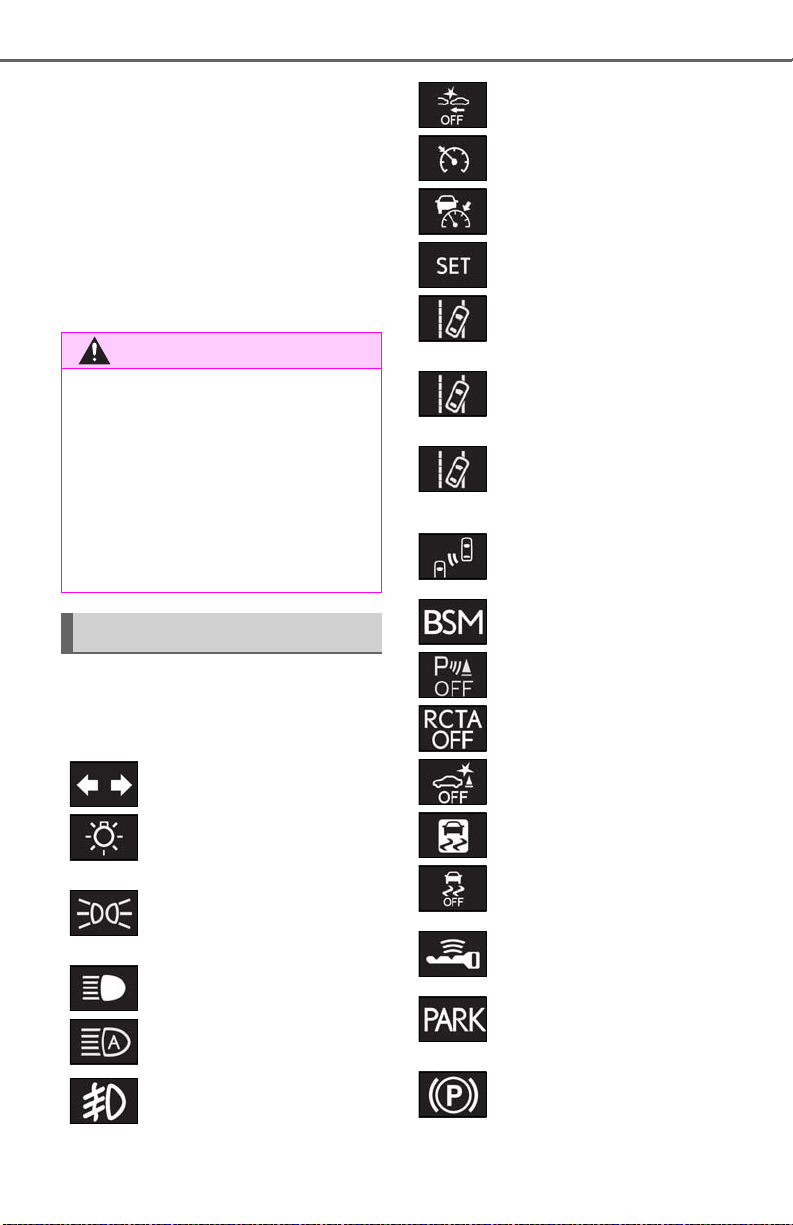
68
WARNING
*1
: These lights come on when the engine
2-1. Instrument cluster
switch is turned to ON to indicate that a
system check is being performed. They
will go off after the engine is on, or after
a few seconds. There may be a malfunction in a system if the lights do not come
on, or go off. Have the vehicle inspected
by your Lexus dealer.
*2
: This light illuminates on the multi-infor-
mation display.
■ If a safety system warning light does
not come on
Should a safety system light such as the
ABS and SRS warning light not come on
when you start the engine, this could
mean that these systems are not available
to help protect you in an accident, which
could result in death or serious injury.
Have the vehicle inspected by your
Lexus dealer immediately if this occurs.
Indicators
The indicators inform the driver of the
operating state of the vehicle’s various
systems.
Turn signal indicator (P.158)
Headlight indicator (P.164)
(U.S.A.)
Tail light indicator (P.164)
(Canada)
Headlight high beam indicator
(P.165)
Automatic High Beam indica-
*1
(P.167)
tor
Fog light indicator (if
equipped) (P.170)
(white)
(green)
(orange)
(U.S.A.)
(Canada)
PCS warning light
Cruise control indicator
*1, 2
(P.185)
*3
(P.203)
Dynamic radar cruise control
*3
indicator
(P.203)
Cruise control “SET” indica-
*3
(P.203)
tor
LTA indicator*3 (P.197)
LTA indicator*3 (P.197)
LTA indicator
*3, 4
(P.197)
BSM outside rear view mirror
indicators
*1, 5
(if equipped)
(P.213)
BSM indicator (if equipped)
(P.213)
Intuitive parking assist OFF indi-
*2
cator
(if equipped) (P.220)
*2
RCTA OFF indicator
(if
equipped) (P.226)
*1, 2
PKSB OFF indicator
(if
equipped) (P.231)
Slip indicator
VSC OFF indicator
*1, 4
(P.245)
*1, 2
(P.245)
Smart access system with push-
*3
button start indicator
(P.150)
Parking brake indicator
(P.159)
Parking brake indicator
(P.159)
Page 69

Brake hold standby indicator
(P.162)
Brake hold operated indicator
(P.162)
Eco Driving Indicator Light
(P.80)
Low outside temperature indi-
*3, 7
cator
(P.70, 73)
Security indicator
63)
“AIR BAG ON/OFF” indica-
*8
(P.39)
tor
(U.S.A.)
“AIR BAG ON/OFF” indica-
*8
(P.39)
tor
(Canada)
Drive mode indicators
*8
(P.61,
*1, 6
2-1. Instrument cluster
*2
*1
: This light comes on when the system is
69
turned off.
*3
*1
: This light illuminates on the multi-infor-
mation display.
*4
: This light flashes to indicate that the sys-
tem is operating.
*5
: This light illuminates on the outside rear
view mirrors.
*6
: Except F SPORT models: This light illu-
minates on the multi-information dis-
2
play.
*7
: When the outside temperature is
Vehicle status information and indicators
approximately 37°F (3°C) or lower, this
indicator will flash for approximately 10
seconds, then stay on.
*8
: This light illuminates on the center
panel.
Except F SPORT models
Eco drive mode indicator
(P.243)
Sport mode indicator
(P.243)
F SPORT models
Eco drive mode indicator
(P.243)
Sport mode indicator
(P.243)
*1
: These lights come on when the engine
switch is turned to ON to indicate that a
system check is being performed. They
will go off after the engine is on, or after
a few seconds. There may be a malfunction in a system if the lights do not come
on, or go off. Have the vehicle inspected
by your Lexus dealer.
Page 70
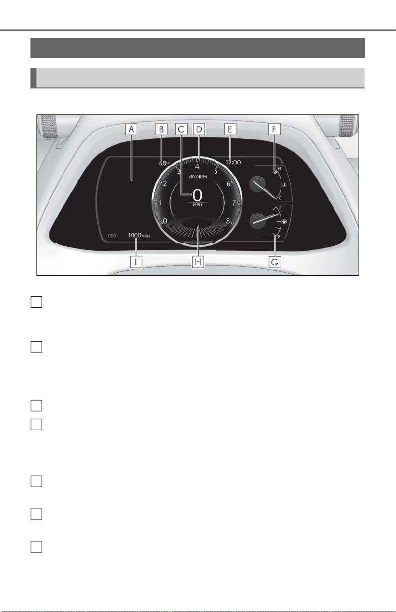
70
A
B
C
D
E
F
G
2-1. Instrument cluster
Gauges and meters (except F SPORT models)
Meter display
■ Locations of gauges and meters
The units of measure may differ depending on the intended destination of the vehicle.
Multi-information display
Presents the driver with a variety of vehicle data (P.77)
Displays warning messages if a malfunction occurs (P.367)
Outside temperature
Displays the outside temperature within the range of -40°F (-40°C) to 122°F (50°C)
Low outside temperature indicator comes on when the ambient temperature is 37°F (3°C)
or lower
Speedometer
Tachometer
Displays the engine speed in revolutions per minute
When Sport mode is selected for the driving mode, the periphery of the tachometer will
change color and the scale of the tachometer will be emphasized.
Clock
Time displayed is linked to the analog clock on the center panel. (P.286)
Engine coolant temperature gauge
Displays the engine coolant temperature
Fuel gauge
Displays the quantity of fuel remaining in the tank
Page 71
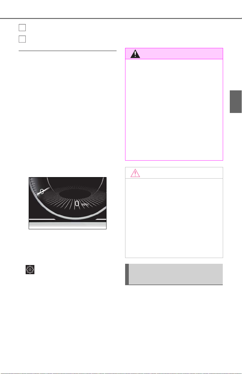
Shift position/shift range (P.154)
H
I
WARNING
NOTICE
Odometer and trip meter display (P.71)
■ Outside temperature display
● In the following situations, the correct
outside temperature may not be displayed, or the display may take longer
than normal to change:
• When stopped, or driving at low speeds
(less than 12 mph [20 km/h])
• When the outside temperature has
changed suddenly (at the entrance/exit of
a garage, tunnel, etc.)
● When “--” or “E” is displayed, the system
may be malfunctioning. Take your vehicle
to your Lexus dealer.
■ Speed unit setting for the speedometer
When the speed unit has been changed
from the default setting, the vehicle speed in
the default unit is also displayed in the
meter.
2-1. Instrument cluster
■ The information display at low tem-
peratures
Allow the interior of the vehicle to warm
up before using the liquid crystal information display. At extremely low temperatures, the information display
monitor may respond slowly, and display
changes may be delayed.
For example, there is a lag between the
driver’s shifting and the new gear number
appearing on the display. This lag could
cause the driver to downshift again,
causing rapid and excessive engine braking and possibly an accident resulting in
death or injury.
■ To prevent damage to the engine and
its components
● Do not let the indicator of the tachom-
eter enter the red zone, which indicates the maximum engine speed.
71
2
Vehicle status information and indicators
■ Liquid crystal display
P.78
■ Customization
The gauges and meters can be customized
on of the multi-information display.
(P.409)
● The engine may be overheating if the
engine coolant temperature gauge is
in the red zone (H). In this case, immediately stop the vehicle in a safe place,
and check the engine after it has
cooled completely. (P.386)
Odometer and trip meter display
■ Display items
Odometer
Displays the total distance the vehicle has
been driven.
Trip meter A/trip meter B
Displays the distance the vehicle has been
driven since the meter was last reset. Trip
Page 72
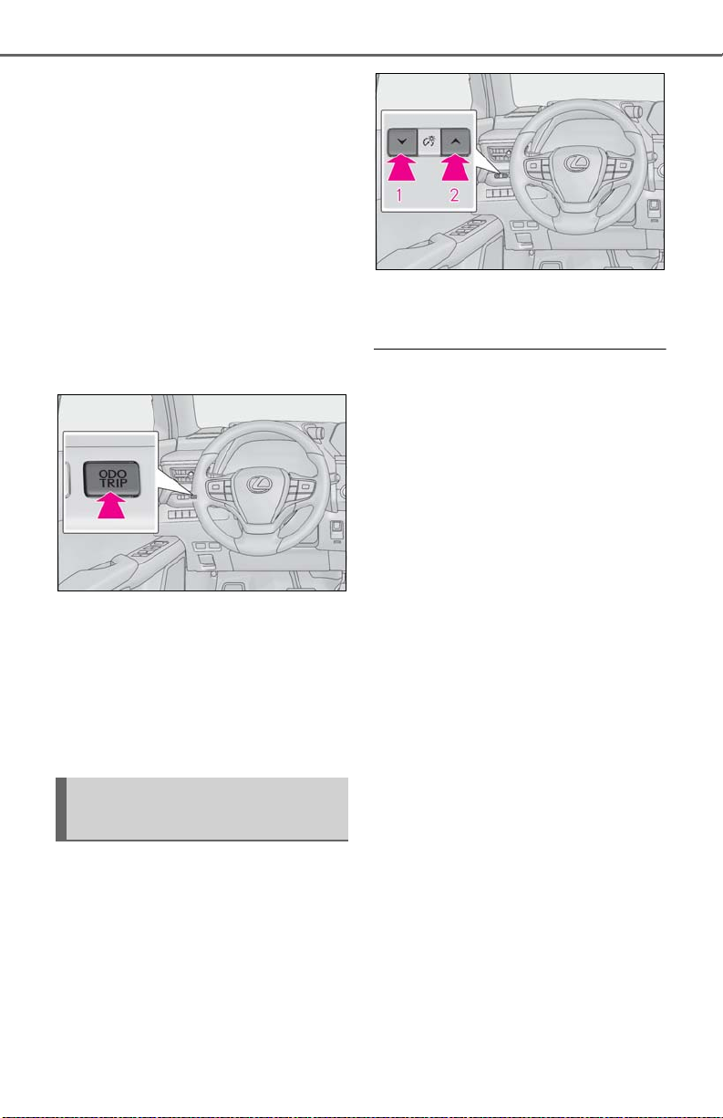
72
meters A and B can be used to record and
display different distances independently.
2-1. Instrument cluster
Distance until next engine oil
change
Displays the distance the vehicle can be
driven until an oil change is necessary.
■ Changing the display
Each time the “ODO TRIP” switch is
pressed, the displayed item will be
changed. When the trip meter is displayed, pressing and holding the switch
will reset the trip meter.
1 Darker
2 Brighter
■ Instrument panel brightness adjustment
The instrument panel brightness levels
when the surroundings are bright (daytime
etc.) and dark (nighttime etc.) can be
adjusted individually.
■ Pop-up display
Distance until the next engine oil
change will displayed when a warning
message indicating that oil maintenance should be performed soon or is
required is displayed.
Changing the instrument panel
light brightness
The brightness of the instrument panel
lights can be adjusted.
Page 73
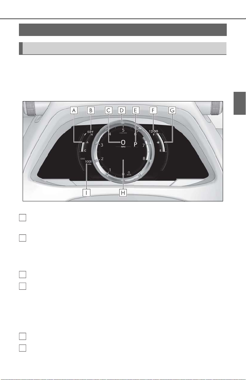
2-1. Instrument cluster
A
B
C
D
E
F
Gauges and meters (F SPORT models)
Meter display
■ Locations of gauges and meters
When the main meter is in the side position, some of the meter displays and the
gauge layout will change.
When the main meter is in the center position
73
2
Vehicle status information and indicators
The units of measure may differ depending on the intended destination of the vehicle.
Engine coolant temperature gauge
Displays the engine coolant temperature
Outside temperature
Displays the outside temperature within the range of -40°F (-40°C) to 122°F (50°C)
Low outside temperature indicator comes on when the ambient temperature is 37°F (3°C)
or lower
Speedometer
Tachometer
Displays the engine speed in revolutions per minute
When Sport mode is selected for the driving mode, the periphery of the tachometer will
change color and the scale of the tachometer will be emphasized.
• Rev indicator
•Rev peak
Shift position/shift range (P.154)
Clock
Page 74
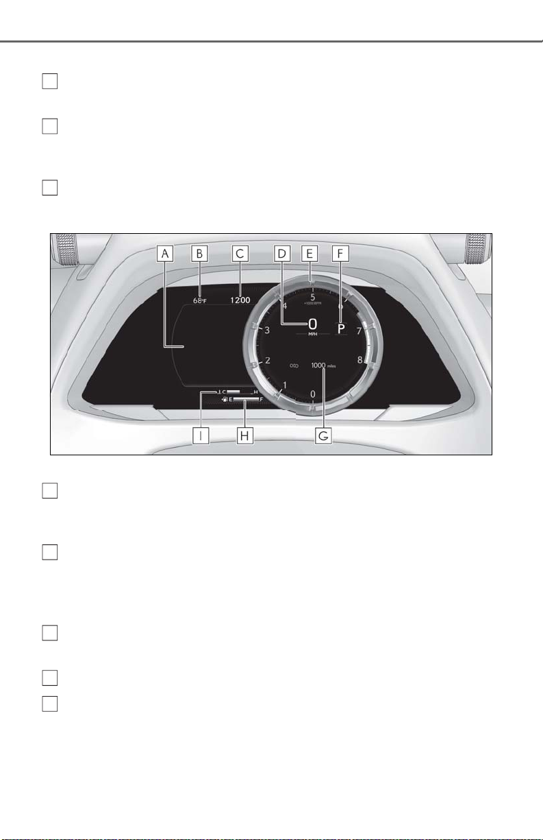
74
G
H
I
A
BCD
E
Time displayed is linked to the analog clock on the center panel. (P.286)
2-1. Instrument cluster
Fuel gauge
Displays the quantity of fuel remaining in the tank
Multi-information display
Presents the driver with a variety of vehicle data (P.77)
Displays warning messages if a malfunction occurs (P.367)
Odometer and trip meter display (P.76)
When the main meter is in the side position
The units of measure may differ depending on the intended destination of the vehicle.
Multi-information display
Presents the driver with a variety of vehicle data (P.77)
Displays warning messages if a malfunction occurs (P.367)
Outside temperature
Displays the outside temperature within the range of -40°F (-40°C) to 122°F (50°C)
Low outside temperature indicator comes on when the ambient temperature is 37°F (3°C)
or lower
Clock
Time displayed is linked to the analog clock on the center panel. (P.286)
Speedometer
Tachometer
Displays the engine speed in revolutions per minute
When Sport mode is selected for the driving mode, the periphery of the tachometer will
change color and the scale of the tachometer will be emphasized.
• Rev indicator
Page 75
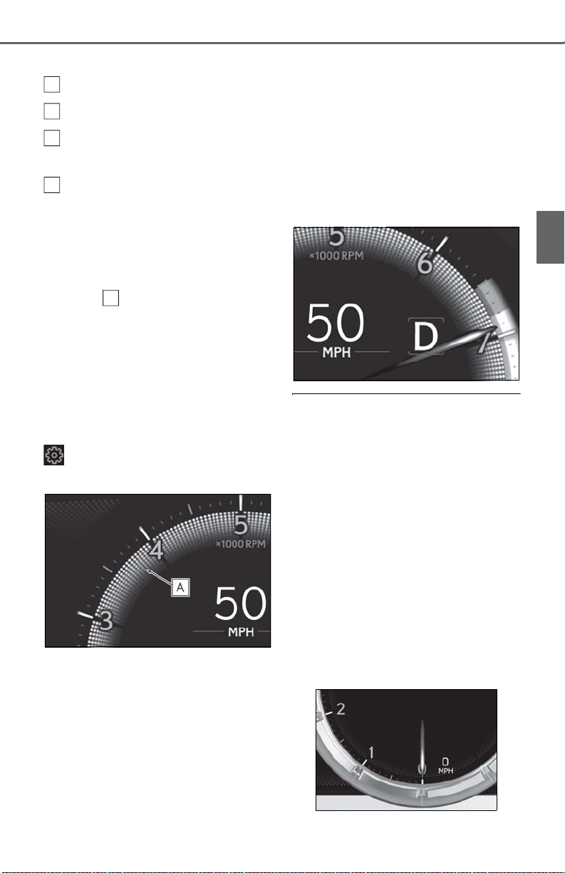
•Rev peak
F
G
H
I
A
Shift position/shift range (P.154)
Odometer and trip meter display (P.76)
Fuel gauge
Displays the quantity of fuel remaining in the tank
Engine coolant temperature gauge
Displays the engine coolant temperature
■ Rev indicator
When the engine speed reaches a set
speed or the red zone, a ring-shaped
indicator ( ) will be displayed on the
tachometer.
The indicators will be displayed in amber
when the engine speed reaches a set
speed, and in red when the engine speed
reaches the red zone.
The engine speed at which the rev indicator will begin to be displayed can be set on
of the multi-information display.
(P.78)
■ Rev peak
When the engine speed reaches or
exceeds 5000 rpm, an afterimage of
the tachometer will be displayed at the
highest engine speed for approximately 1 second.
2-1. Instrument cluster
■ Outside temperature display
● In the following situations, the correct
outside temperature may not be displayed, or the display may take longer
than normal to change:
• When stopped, or driving at low speeds
(less than 12 mph [20 km/h])
• When the outside temperature has
changed suddenly (at the entrance/exit of
a garage, tunnel, etc.)
● When “--” or “E” is displayed, the system
may be malfunctioning. Take your vehicle
to your Lexus dealer.
■ Speed unit setting for the speedometer
When the speed unit has been changed
from the default setting, the vehicle speed in
the default unit is also displayed in the
meter.
75
2
Vehicle status information and indicators
Page 76
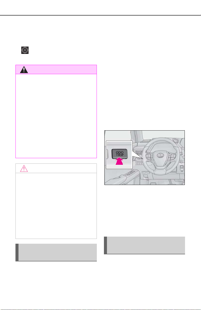
76
WARNING
NOTICE
2-1. Instrument cluster
■ Liquid crystal display
P.78
■ Customization
The gauges and meters can be customized
on of the multi-information display.
(P.409)
■ The information display at low tem-
peratures
Allow the interior of the vehicle to warm
up before using the liquid crystal information display. At extremely low temperatures, the information display
monitor may respond slowly, and display
changes may be delayed.
For example, there is a lag between the
driver’s shifting and the new gear number
appearing on the display. This lag could
cause the driver to downshift again,
causing rapid and excessive engine braking and possibly an accident resulting in
death or injury.
Trip meter A/trip meter B
Displays the distance the vehicle has been
driven since the meter was last reset. Trip
meters A and B can be used to record and
display different distances independently.
Distance until next engine oil
change
Displays the distance the vehicle can be
driven until an oil change is necessary.
■ Changing the display
Each time the “ODO TRIP” switch is
pressed, the displayed item will be
changed. When the trip meter is displayed, pressing and holding the switch
will reset the trip meter.
■ To prevent damage to the engine and
its components
● Do not let the indicator of the tachom-
eter enter the red zone, which indicates the maximum engine speed.
● The engine may be overheating if the
engine coolant temperature gauge is
in the red zone (H). In this case, immediately stop the vehicle in a safe place,
and check the engine after it has
cooled completely. (P.386)
Odometer and trip meter display
■ Display items
Odometer
Displays the total distance the vehicle has
been driven.
■ Pop-up display
Distance until the next engine oil
change will displayed when a warning
message indicating that oil maintenance should be performed soon or is
required is displayed.
Changing the instrument panel
light brightness
The brightness of the instrument panel
lights can be adjusted.
Page 77
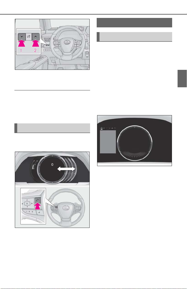
1 Darker
2 Brighter
■ Instrument panel brightness adjustment
The instrument panel brightness levels
when the surroundings are bright (daytime
etc.) and dark (nighttime etc.) can be
adjusted individually.
Changing the display
The display can be switched between
the center and side positions.
2-1. Instrument cluster
Multi-information display
Display and menu icons
■ Display (except F SPORT models)
By selecting menu icons on the multiinformation display, a variety of drivingrelated information can be displayed.
The multi-information display can also
be used to change display settings and
other vehicle settings.
Warning or suggestion/advice pop-up
displays are also displayed in certain
situations.
77
2
Vehicle status information and indicators
■ Display (F SPORT models)
When the main meter is in the cen-
ter position
The multi-information display presents
the driver with a variety of drivingrelated information.
Warning or suggestion/advice pop-up
displays are also displayed in certain
situations.
Page 78
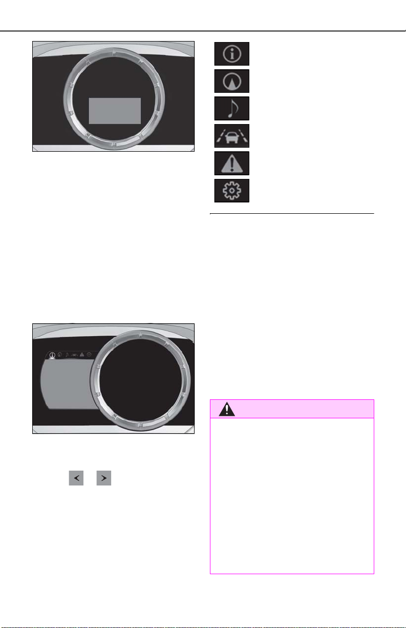
78
WARNING
When the main meter is in the side
2-1. Instrument cluster
position
By selecting menu icons on the multiinformation display, a variety of drivingrelated information can be displayed.
The multi-information display can also
be used to change display settings and
other vehicle settings.
Warning or suggestion/advice pop-up
displays are also displayed in certain
situations.
Driving information display
(P.79)
Navigation system-linked display (if equipped) (P.81)
Audio system-linked display
(P.81)
Driving support system information display (P.82)
Warning message display
(P.367)
Settings display (P.82)
■ Opening image display
When the engine switch is in ACC or ON,
the opening image is displayed on the multiinformation display.
While the opening image is being displayed, the meter display cannot be
changed even if the drive mode is changed.
When the opening image is finished, the
meter display for the currently selected
mode will be displayed.
■ Liquid crystal display
Small spots or light spots may appear on the
display. This phenomenon is characteristic
of liquid crystal displays, and there is no
problem continuing to use the display.
■ Menu icons
The menu icons will be displayed by
pressing or of the meter con-
trol switches (P.79).
F SPORT models: The menu icons can be
displayed when the main meter is in the
side position.
■ Caution for use while driving
● When operating the multi-information
display while driving, pay extra attention to the safety of the area around the
vehicle.
● Do not look continuously at the multi-
information display while driving as
you may fail to see pedestrians, objects
on the road, etc. ahead of the vehicle.
■ The information display at low tem-
peratures
P.71, 76
Page 79
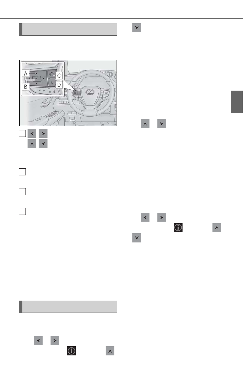
2-1. Instrument cluster
A
B
C
D
79
Changing the meter display
The multi-information display is operated using the meter control switches.
/ : Select menu icons
/ : Change displayed content, scroll up/down the screen or
move the cursor up/down
Press: Enter/Set
Press and hold: Reset
Move the main meter
the previous screen
Call sending/receiving and history
display
Linked with the hands-free system,
sending or receiving call is displayed. For details regarding the
hands-free system, refer to the
“NAVIGATION AND MULTIMEDIA SYSTEM OWNER’S MANUAL”.
*
:F SPORT models
*
or return to
or to display the following items:
Drive information 1
Drive information 2
Eco Driving Indicator
Tire pressure
Display off
■ Display items (F SPORT models)
When the main meter is in the cen-
ter position
Press or of the meter control
switches to display the following items:
Drive information 1
Drive information 2
Tire pressure
Units
Display off
When the main meter is in the side
position
Press or of the meter control
switches and select . Then press
or to display the following items:
Drive information 1
Drive information 2
Eco Driving Indicator
G-force
Tire pressure
2
Vehicle status information and indicators
Drive information
■ Display items (except F SPORT
models)
Press or of the meter control
switches and select . Then press
Display off
■ Drive information 1/Drive infor-
mation 2
2 of the following drive information can
be displayed in each screen.
Displayed items can be changed on
Page 80
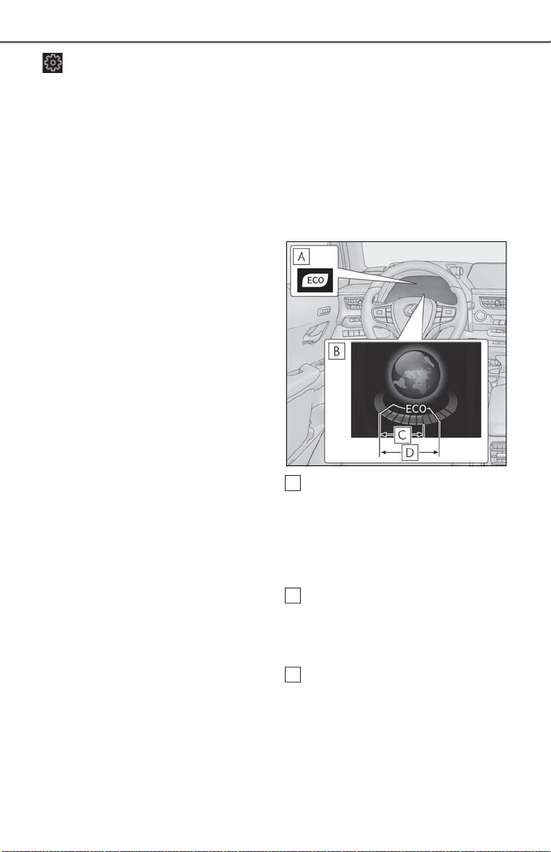
80
ABC
2-1. Instrument cluster
. (P.82)
Use the displayed values as a reference
only.
Current fuel consumption
Displays instantaneous current fuel consumption
Average fuel economy
After reset: Displays average fuel consumption since the display was reset
*1
After start: Displays average fuel consumption since the engine was started
After refuel: Displays average fuel consumption since refuel
Average vehicle speed
After reset: Displays average vehicle
speed since the display was reset
*1
After start: Displays average vehicle speed
since the engine was started
Driven distance
Displays the distance driven since the
engine was started
Elapsed time
After reset: Displays elapsed time since the
display was reset
*1
After start: Displays elapsed time since the
engine was started
Driving range
Displays driving range with remaining
*2, 3
fuel
Other
No item
*1
: To reset, display the desired item and
press and hold “OK” of the meter control switches.
*2
: This distance is computed based on
your average fuel consumption. As a
result, the actual distance that can be
driven may differ from that displayed.
*3
: When only a small amount of fuel is
added to the tank, the display may not
be updated.
When refueling, turn the engine switch
off. If the vehicle is refueled without
turning the engine switch off, the display
may not be updated.
■ Eco Driving Indicator
Eco Driving Indicator Light
During Eco-friendly acceleration (Eco
driving), the Eco Driving Indicator Light
will turn on. When the acceleration
exceeds the Zone of Eco driving, or when
the vehicle is stopped, the light turns off.
Eco Driving Indicator Zone Display
Suggests the Zone of Eco driving with current Eco driving ratio based on acceleration.
Eco driving ratio based on acceleration
If the acceleration exceeds the Zone of
Eco driving, the right side of the Eco Driving Indicator Zone Display will illuminate.
At this time, the Eco Driving Indicator Light
will turn off.
Page 81
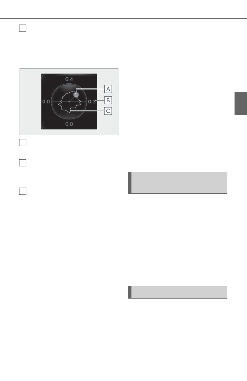
2-1. Instrument cluster
D
ABC
81
Zone of Eco driving
■ G-force (F SPORT models)
Displays lateral G-forces on the vehicle.
Acceleration G-force on the vehicle
Current G-force value (analyzed
value of front/rear and left/right Gforces)
Record of the maximum G-forces
This display is intended for use as a guideline. Depending on factors such as the road
surface condition, temperature and vehicle
speed, the display may not show the actual
condition of the vehicle.
Resetting the record of maximum
G-forces
Press and hold “OK” of the meter control
switches to reset the record.
Peak hold function
If lateral G-forces of 0.5 G or greater are
generated, the G-force value display will
turn amber and be held for 2 seconds.
■ Tire pressure
P.330
Unlike the units setting performed on the
settings display, the units setting performed on the drive information display
can be changed while driving.
■ Display OFF
Displays a blank screen.
■ Eco Driving Indicator
Eco Driving Indicator will not operate
under the following conditions:
● The shift lever is in any position other than
D.
● A paddle shift switch (if equipped) is
operated.
● The driving mode is set to other than nor-
mal and Eco drive mode.
● The vehicle speed is approximately 80
mph (130 km/h) or higher.
Navigation system-linked display (if equipped)
Select to display the following navigation system-linked information.
Route guidance to destination
Compass display
■ Route guidance to destination display
When the route guidance to destination
display is enabled on the head-up display, it
will not be displayed on the multi-information display. (P.84)
Audio system-linked display
Select to enable selection of an audio
source or track on the meter using the
meter control switches.
2
Vehicle status information and indicators
■ Units (F SPORT models)
The units of measure used can be
changed while driving.
Page 82

82
2-1. Instrument cluster
Driving support system information display
Select to display the operational status
of the following systems:
LTA (Lane Tracing Assist) (P.192)
Dynamic radar cruise control with
full-speed range (P.203)
RSA (Road Sign Assist) (if
equipped) (P.201)
Warning message display
Select to display warning messages
and measures to be taken if a malfunction is detected. (P.367)
Settings display
■ Meter display settings that can be
changed
Language
Select to change the language displayed.
Units
Select to change the units of measure displayed.
Speedometer display (except F
SPORT models)
Select to set the display of the speedometer to digital/analog.
Drive information 1/Drive informa-
tion 2
Select to select up to 2 items (P.79) that
will be displayed on each Drive information
screen (Drive information 1 screen and
Drive information 2 screen) respectively.
Clock
Select to switch between 12-hour display
and 24-hour display.
Pop-up display
Select to enable/disable some pop-up displays for each relevant system.
Accent color
Select to change the accent color on the
screen, such as the cursor color.
Rev indicator (F SPORT models)
• Select to enable/disable the rev indicator.
• Select to set the engine speed at which
the rev indicator (amber) will begin to be
displayed.
Rev peak (F SPORT models)
Select to enable/disable the rev peak.
Eco Driving Indicator Light
Select to enable/disable the Eco Driving
Indicator Light.
Default setting
Select to reset the meter display settings to
the default setting.
■ Suspension of the settings display
● Some settings cannot be changed while
driving. When changing settings, park
the vehicle in a safe place.
● If a warning message is displayed, opera-
tion of the settings display will be suspended.
Page 83
WARNING
■ Cautions during setting up the dis-
NOTICE
play
As the engine needs to be running
during setting up the display, ensure that
the vehicle is parked in a place with adequate ventilation. In a closed area such as
a garage, exhaust gases including harmful carbon monoxide (CO) may collect
and enter the vehicle. This may lead to
death or a serious health hazard.
■ During setting up the display
To prevent battery discharge, ensure that
the engine is running while setting up the
display features.
Suggestion function
Displays suggestions to the driver in
the following situations. To select a
response to a displayed suggestion,
use the meter control switches.
■ Suggestion to enable the power
back door
If the power back door system is disabled on of the multi-information
display (P.78) and the power back
door switch on the instrument panel is
operated, a suggestion message will be
displayed asking if you wish to enable
the power back door system. To enable
the power back door system, select
“Yes”.
2-1. Instrument cluster
■ Suggestion to turn on the head-
lights
If the headlight switch is in other than
or position, and the vehicle
speed is 3 mph (5 km/h) or higher for
a certain amount of time when the surroundings are dark, a suggestion message will be displayed.
■ Suggestion to turn off the head-
lights
If the headlights are left on for a certain
amount of time with the headlight
switch in or position after the
engine switch has been turned off, a
suggestion message will be displayed
asking if you wish to turn the headlights
off.
To turn the headlights off, select “Yes”.
If a front door is opened after the engine
switch is turned off, this suggestion message will not be displayed.
■ Customization
Some functions can be customized.
(P.409)
83
2
Vehicle status information and indicators
After enabling the power back door
system, press the power back door
switch again to open or close the
power back door.
Page 84
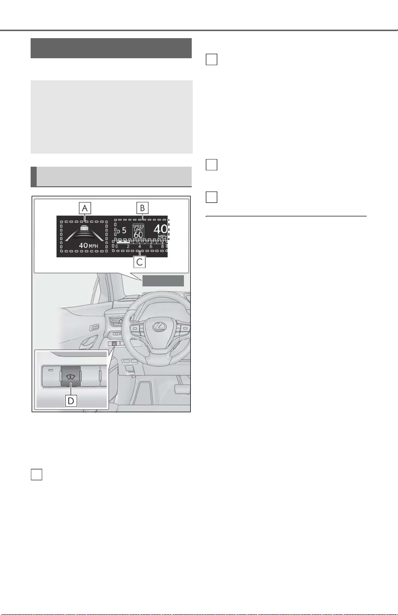
84
A
B
C
D
2-1. Instrument cluster
Head-up display
*
:If equipped
*
The head-up display projects a variety of driving-related information
and the operating state of the driving support systems on the windshield.
System components
Illustrations used in this text are intended as
examples, and may differ from the image
that is actually displayed by the head-up
display.
Driving support system display
area (P.86)
Navigation system-linked display
area (if equipped)
Displays the following items which are
linked to the navigation system:
• Route guidance to destination
•Street name
• Compass (heading-up display)
Driving information display area
Displays the following items:
• Speed limit of the current road (linked to
the navigation system) (U.S.A. only)
• RSA (Road Sign Assist) display (if
equipped) (P.201)
• Speedometer
• Shift position/shift range (P.154)
Tachometer/Eco Driving Indicator
display area (P.87)
Head-up display switch
■ Head-up display will operate when
The engine switch is in ON.
■ When using the head-up display
The head-up display may seem dark or hard
to see when viewed through sunglasses,
especially polarized sunglasses. Adjust the
brightness of the head-up display or
remove your sunglasses.
■ Street name display
Only street names which are included in the
map data will be displayed.
■ Outside temperature display
● In the following situations, the outside
temperature is displayed.
• When the ambient temperature is
approximately 37°F (3°C) or lower (In
this case, the outside temperature display
will be displayed and the low outside temperature indicator will flash for approximately 10 seconds.)
• After the opening image (P.78) is displayed (The outside temperature display
will be displayed for approximately 10
seconds.)
● In the following situations, the correct
outside temperature may not be displayed, or the display may take longer
than normal to change:
• When stopped, or driving at low speeds
(less than 12 mph [20 km/h])
• When the outside temperature has
changed suddenly (at the entrance/exit of
Page 85
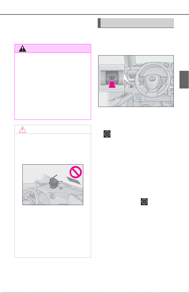
2-1. Instrument cluster
WARNING
NOTICE
85
a garage, tunnel, etc.)
● When “--” or “E” is displayed, the system
may be malfunctioning. Take your vehicle
to your Lexus dealer.
■ When using the head-up display
● Check that the position and brightness
of the head-up display image does not
interfere with safe driving. Incorrect
adjustment of the image’s position or
brightness may obstruct the driver’s
view and lead to an accident, resulting
in death or serious injury.
● Do not continuously look at the head-
up display while driving as you may fail
to see pedestrians, objects on the
road, etc. ahead of the vehicle.
■ Head-up display projector
● Do not place any drinks near the head-
up display projector. If the projector
gets wet, electrical malfunctions may
result.
● Do not place anything on or put stick-
ers onto the head-up display projector.
Doing so could interrupt head-up display indications.
● Do not touch the inside of the head-up
display projector or thrust sharp edges
or the like into the projector.
Doing so could cause mechanical malfunctions.
Using the head-up display
■ Enabling/disabling the head-up dis-
play
Press the head-up display switch.
■ Changing settings of the head-up
display
The following settings can be changed
on of the multi-information display.
(P.410)
Brightness and vertical position of
the head-up display
Select to adjust the brightness or vertical
position of the head-up display.
Tachometer/Eco Driving Indicator
Select to display the tachometer, Eco Driving Indicator or no content.
*
: To set this item, select on the multi-
information display, select “Vehicle Settings” and select “HUD”.
Display content
Select to enable/disable the following
items:
• Route guidance to destination/street
name
• Driving support system display
• Compass (heading-up display)
• Audio system operation status
*1
*2
2
Vehicle status information and indicators
*
Page 86
86
WARNING
NOTICE
*1
: To set this item, select on the multi-
*2
: Make sure to enable this display when
Display angle
Select to adjust the angle of the head-up
display.
*
: To set this item, select on the multi-
information display, select “Vehicle Settings” and select “HUD”.
2-1. Instrument cluster
information display, select “Vehicle Settings” and select “HUD”.
using the driving support systems
*
■ Caution for changing settings of the
head-up display
As the engine needs to be running while
changing the settings of the head-up display , ens ure t hat t he ve hicl e is p arke d in a
place with adequate ventilation. In a
closed area such as a garage, exhaust
gases including harmful carbon monoxide (CO) may collect and enter the vehicle. This may lead to death or a serious
health hazard.
■ Enabling/disabling of the head-up dis-
play
If the head-up display is disabled, it will
remain disabled when the engine switch is
turned off then back to ON.
■ Display brightness
The brightness of the head-up display can
be adjusted on of the multi-information
display. Also, it is automatically adjusted
according to the ambient brightness.
■ Head-up display automatic position
adjustment (vehicles with driving position memory)
If the display position is recorded into memory, the head-up display will be automatically adjusted to the desired position.
(P.121)
■ When the battery is disconnected
The customize settings of the head-up display will be reset.
■ When changing the settings of the
head-up display
To prevent battery discharge, ensure that
the engine is running while changing the
settings of the head-up display.
Driving support system display
area
Displays the operational status of the
following systems:
LTA (Lane Tracing Assist) (P.192)
Dynamic radar cruise control with
full-speed range (P.203)
Details of content displayed on the headup display may differ from that displayed
on the multi-information display. For
details, refer to the explanation of each system.
Pop-up display
Pop-up displays for the following systems will be displayed when necessary.
■ Driving support systems
Displays a warning/suggestion/advice
message or the operating state of a rel-
Page 87
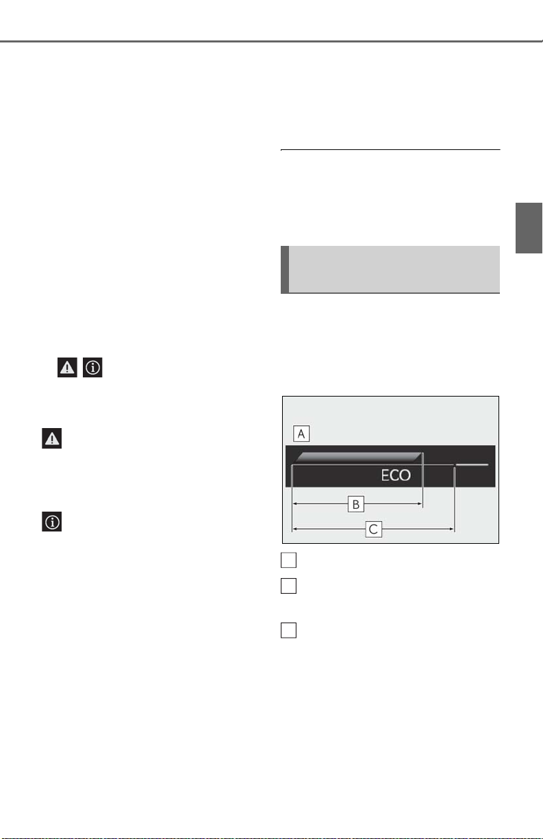
2-1. Instrument cluster
A
B
C
87
evant system.
PCS (Pre-Collision System)
(P.185)
Intuitive parking assist (if equipped)
(P.219)
Parking Support Brake function (for
static objects) (if equipped)
(P.235)
Brake Override System (P.141)
Drive-Start Control (P.141)
Details of content displayed on the headup display may differ from that displayed
on the multi-information display. For
details, refer to the explanation of each system.
■ / icons
These icons are linked to the multiinformation display
: Master warning icon
Displayed when a warning message is displayed on the multi-information display.
(P.367)
operated.
■ Hands-free system status
Displayed when the hands-free system
is operated.
■ When a pop-up display is displayed
When a pop-up display is displayed, a current display may no longer be displayed. In
this case, the display will return after the
pop-up display disappears.
Tachometer/Eco Driving Indicator display area
■ Tachometer
Displays the engine speed in revolutions per minute.
■ Eco Driving Indicator
2
Vehicle status information and indicators
: Information icon
Displayed when a suggestion pop-up display (P.83) or advice pop-up display is
displayed on the multi-information display.
■ Warning message
Some warning messages are displayed
when necessary, according to certain
conditions.
Details of content displayed on the headup display may differ from that displayed
on the multi-information display.
■ Audio system operation status
Displayed when an audio remote control switch on the steering wheel is
Eco Driving Indicator Zone Display
Eco driving ratio based on acceler-
ation
Zone of Eco driving
Displayed content is the same as that displayed on the multi-information display
(Eco Driving Indicator). For details, refer to
P.80.
Page 88
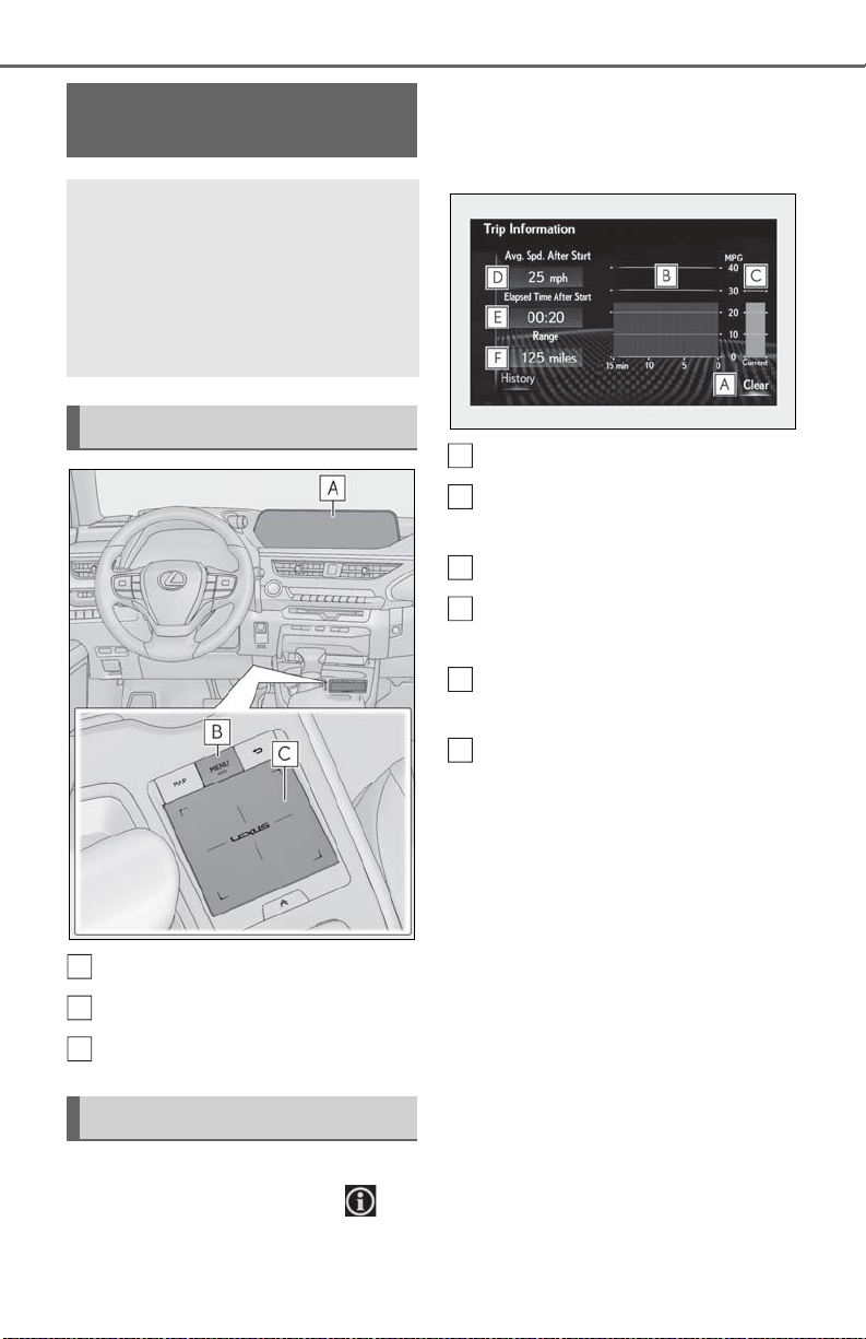
88
A
B
C
A
B
C
D
E
F
2-1. Instrument cluster
Fuel consumption information
Fuel consumption information can
be displayed on the multi-information display and Center Display.
10.3-inch display model: The consumption screen can be displayed
on the side display.
System components
■ Trip information
If a screen other than “Trip Information”
is displayed, select “Trip Information”.
Resetting the consumption data
Fuel consumption in the past 15
minutes
Current fuel consumption
Average vehicle speed since the
engine was started.
Elapsed time since the engine was
started.
Center Display
“MENU” button
Touchpad
Consumption
Press the “MENU” button on the
Remote Touch, and then select on
the screen.
Cruising range
Average fuel consumption for the past 15
minutes is divided by color into past averages and averages attained since the
engine switch was last turned to ON. Use
the displayed average fuel consumption as
a reference.
The image is an example only, and may
vary slightly from actual conditions.
■ History
If a screen other than “History” is displayed, select “History”.
Page 89
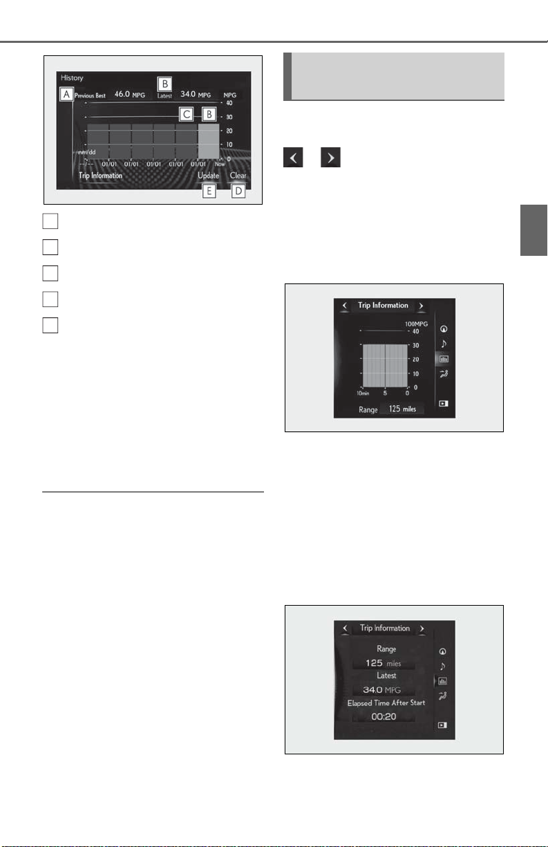
Best recorded fuel consumption
A
B
C
D
E
Latest fuel consumption
Previous fuel consumption record
Resetting the history data
Updating the latest fuel consump-
tion data
The average fuel consumption history is
divided by color into past averages and the
average fuel consumption since the last
updated. Use the displayed average fuel
consumption as a reference.
The image is an example only, and may
vary slightly from actual conditions.
■ Updating the history data
Update the latest fuel consumption by
selecting “Update” to measure the current
fuel consumption again.
■ Resetting the data
The fuel consumption data can be deleted
by selecting “Clear”.
■ Cruising range
Displays the estimated maximum distance
that can be driven with the quantity of fuel
remaining.
This distance is computed based on your
average fuel consumption.
As a result, the actual distance that can be
driven may differ from that displayed.
2-1. Instrument cluster
Using the side display (10.3-inch
display model)
Display the vehicle information on the
side display (P.259), and then select
or to display the desired
screen.
■ Trip information (type A)
Displays the average fuel consumption
for the past 10 minutes in 1 minute
intervals, as well as the cruising range.
The image is an example only, and may
vary slightly from actual conditions.
Use the displayed average fuel consumption as a reference.
■ Trip information (type B)
Displays the cruising range, latest fuel
consumption and the amount of time
elapsed since the engine was started.
89
2
Vehicle status information and indicators
The image is an example only, and may
vary slightly from actual conditions.
Page 90
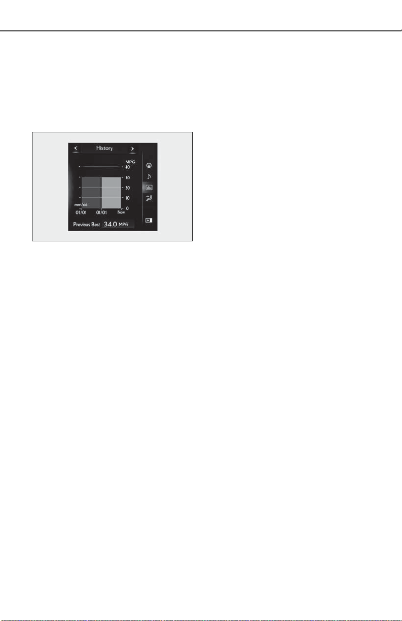
90
Use the displayed average fuel consumption as a reference.
■ History
2-1. Instrument cluster
Displays the average fuel consumption,
previous average fuel consumption
and highest fuel consumption.
The image is an example only, and may
vary slightly from actual conditions.
Use the displayed average fuel consumption as a reference.
Page 91

91
Before driving
3-1. Key information
Keys ................................................... 92
3-2. Opening, closing and locking the
doors
Side doors ....................................... 96
Back door......................................100
Smart access system with push-
button start.................................. 112
3-3. Adjusting the seats
Front seats...................................... 119
Rear seats...................................... 120
Driving position memory .........121
Head restraints............................ 124
3-4. Adjusting the steering wheel and
mirrors
Steering wheel............................. 127
Inside rear view mirror.............128
Outside rear view mirrors......130
3-5. Opening, closing the windows
and moon roof
Power windows........................... 133
Moon roof .....................................135
3
3
Before driving
Page 92
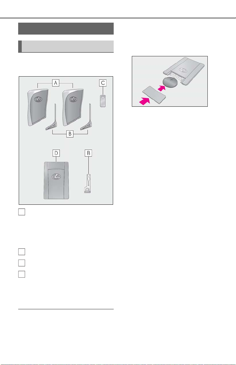
92
A
B
C
D
3-1.Key information
3-1. Key information
Keys
Key types
The following keys are provided with
the vehicle.
Electronic keys
• Operating the smart access system with
push-button start (P.112)
• Operating the wireless remote control
function
Mechanical keys
Key number plate
Card key (electronic key) (if
equipped)
Operating the smart access system with
push-button start (P.112)
■ Card key (if equipped)
● The mechanical key that is stored inside
the card key should be used only if a
problem arises, such as when the card
key does not operate properly.
● If the battery cover is not installed and the
battery falls out or if the battery was
removed because the key got wet, reinstall the battery with the positive terminal
facing the Lexus emblem.
● The card key is not waterproof.
■ When riding in an aircraft
When bringing an electronic key onto an
aircraft, make sure you do not press any
buttons on the electronic key while inside
the aircraft cabin. If you are carrying an
electronic key in your bag, etc., ensure that
the buttons are not likely to be pressed accidentally. Pressing a button may cause the
electronic key to emit radio waves that
could interfere with the operation of the aircraft.
■ Electronic key battery depletion
● The standard battery life is 1 to 2 years.
(The card key battery life is about a year
and a half.)
● If the battery becomes low, an alarm will
sound in the cabin when the engine stops.
● To reduce key battery de pletion when the
electronic key is to not be used for long
periods of time, set the electronic key to
the battery-saving mode. (P.113)
● As the electronic key always receives
radio waves, the battery will become
depleted even if the electronic key is not
used. The following symptoms indicate
that the electronic key battery may be
depleted. Replace the battery when necessary. (P.341)
• The smart access system with push-button start or the wireless remote control
does not operate.
• The detection area becomes smaller.
• The LED indicator on the key surface
does not turn on.
You can replace the battery by yourself
Page 93

3-1. Key information
NOTICE
93
(P.341). However, as there is a danger
that the electronic key may be damaged, it
is recommended that replacement be carried out by your Lexus dealer.
● To avoid serious deterioration, do not
leave the electronic key within 3 ft. (1 m)
of the following electrical appliances that
produce a magnetic field:
•TVs
• Personal computers
• Cellular phones, cordless phones and
battery chargers
• Recharging cellular phones or cordless
phones
• Table lamps
• Induction cookers
■ Replacing the battery
P.341
■ Confirmation of the registered key
number
The number of keys already registered to
the vehicle can be confirmed. Ask your
Lexus dealer for details.
■ If “A New Key has been Registered
Contact Your Dealer for Details” is
shown on the multi-information display
This message will be displayed each time
the driver’s door is opened when the doors
are unlocked from the outside for approximately 10 days after a new electronic key
has been registered. If this message is displayed but you have not had a new electronic key registered, ask your Lexus dealer
to check if an unknown electronic key
(other than those in your possession) has
been registered.
■ To prevent key damage
● Do not drop the keys, subject them to
strong shocks or bend them.
● Do not expose the keys to high tem-
peratures for long periods of time.
● Do not get the keys wet or wash them
in an ultrasonic washer, etc.
● Do not attach metallic or magnetic
materials to the keys or place the keys
close to such materials.
● Do not disassemble the keys.
● Do not attach a sticker or anything else
to the surface of the electronic key.
● Do not place the keys near objects that
produce magnetic fields, such as TVs,
audio systems and induction cookers,
or medical electrical equipment, such
as low-frequency therapy equipment.
■ Carrying the electronic key on your
person
Carry the electronic key 3.9 in. (10 cm)
or more away from electric appliances
that are turned on. Radio waves emitted
from electric appliances within 3.9 in. (10
cm) of the electronic key may interfere
with the key, causing the key to not function properly.
■ In case of a smart access system with
push-button start malfunction or
other key-related problems
P.380
■ When an electronic key is lost
P.379
■ Handling the card key
● If the battery or card key terminals get
wet, the battery may corrode and the
card key may stop working.
If the key is dropped into water, or if
drinking water, etc., is spilled on the
key, immediately remove the battery
cover and wipe the battery and terminals. (To remove the battery cover,
lightly grasp and pull it.) If the battery is
corroded, have your Lexus dealer
replace the battery.
● Do not crush the battery cover or use
a screwdriver to remove the battery
cover.
Forcibly removing the battery cover
may bend or damage the key.
3
Before driving
Page 94
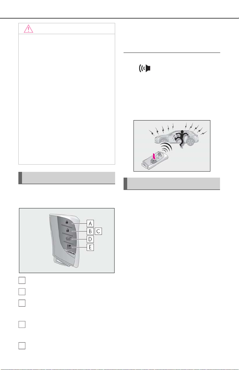
94
NOTICE
A
B
C
D
E
● If the battery cover is frequently
● When installing the battery, make sure
● The surface of the card key may be
• The card key is carried together with
• The card key is scraped with a sharp
• The surface of the card key is wiped
3-1. Key information
removed, the battery cover may
become loose.
to check the direction of the battery.
Installing the battery in the wrong
direction may cause the battery to
deplete rapidly.
damaged, or its coating may peel off in
the following situations:
hard objects, such as coins and keys.
object, such as the tip of a mechanical
pencil.
with thinner or benzene.
*1
: If equipped
*2
: This setting must be customized at your
Lexus dealer.
■ Theft deterrent panic mode
When is pressed for longer than
about 1 second, an alarm will sound intermittently and the vehicle lights will flash to
deter any person from trying to break into
or damage your vehicle.
To stop the alarm, press any button on the
electronic key.
Wireless remote control
The electronic keys are equipped with
the following wireless remote control:
Locks all the doors (P.96)
Unlocks all the doors (P.96)
Opens the windows and moon
*1, 2
roof
Opens and closes the power back
door
Sounds the alarm (P.94)
(P.96)
*1
(P.103)
Using the mechanical key
To take out the mechanical key, push
the release button and take the key out.
The mechanical key can only be inserted in
one direction, as the key only has grooves
on one side. If the key cannot be inserted in
a lock cylinder, turn it over and re-attempt
to insert it.
After using the mechanical key, store it in
the electronic key. Carry the mechanical
key together with the electronic key. If the
electronic key battery is depleted or the
entry function does not operate properly,
you will need the mechanical key.
(P.380)
Page 95
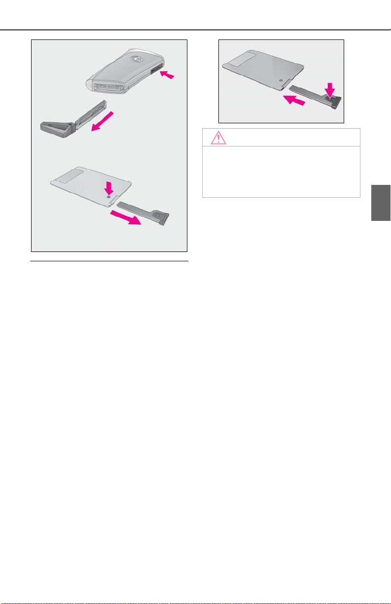
■ When required to leave the vehicle’s
NOTICE
key with a parking attendant
Lock the glove box as circumstances
demand. (P.279)
Remove the mechanical key for your own
use and provide the attendant with the electronic key only.
■ If you lose your mechanical keys
P.379
■ If a wrong key is used
The key cylinder rotates freely to isolate
inside mechanism.
■ Card key (if equipped)
● If it is difficult to take out the mechanical
key, push down the release button using a
pen tip, etc. If it is still difficult to pull it out,
use a coin, etc.
● To store the mechanical key in the card
key, insert it while pressing the release
button.
3-1. Key information
■ Handling the card key
Do not apply excess force when inserting
the mechanical key into the card key.
Doing so may damage the card key.
95
3
Before driving
Page 96
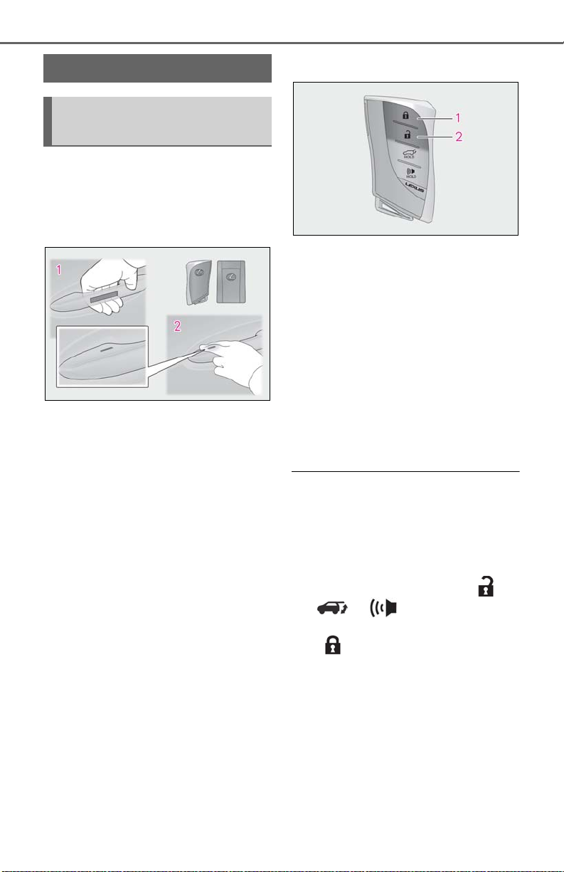
96
3-2.Opening, closing and locking the doors
3-2. Opening, closing and locking the doors
Side doors
Unlocking and locking the doors
from the outside
■ Smart access system with push-
button start
Carry the electronic key to enable this
function.
1 Grip the driver’s door handle to
unlock the door. Holding the
driver’s door handle for approximately 2 seconds unlocks all the
doors. Grip the front passenger
door handle to unlock all the
*
doors.
Make sure to touch the sensor on the back
of the handle.
The doors cannot be unlocked for 3 seconds after the doors are locked.
*
: The door unlock settings can be
changed.
2 Touch the lock sensor (the indenta-
tion on the upper part of the front
door handle) to lock all the doors.
Check that the door is securely locked.
■ Wireless remote control
1 Locks all the doors
Check that the door is securely locked.
2 Unlocks all the doors
Pressing the button unlocks the driver’s
door. Pressing the button again within 3
seconds unlocks the other doors.
Press and hold to open the windows and
moon roof
*1
: If equipped
*2
: This setting must be customized at your
■ Switching the door unlock function
It is possible to set which doors the entry
function unlocks using the wireless remote
control.
1 Turn the engine switch off.
2 When the indicator light on the key sur-
The setting changes each time an operation
is performed, as shown below. (When
changing the setting continuously, release
the buttons, wait for at least 5 seconds, and
repeat step 2.)
*1, 2
Lexus dealer.
face is not on, press and hold ,
or for approximately 5
seconds while pressing and holding
.
Page 97
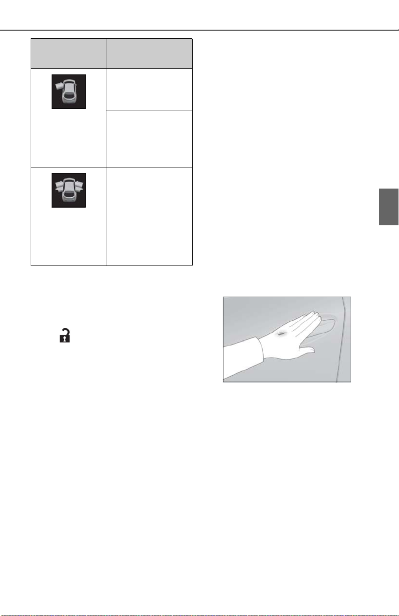
3-2. Opening, closing and locking the doors
97
Multi-information
display/Beep
Unlocking function
Holding the driver’s
door handle unlocks
only the driver’s door.
Exterior: Beeps 3
times
Interior: Pings
once
Holding the front pas-
senger door handle
unlocks all the doors.
Holding a front door
Exterior: Beeps
twice
handle unlocks all the
doors.
Interior: Pings
once
To prevent unintended triggering of the
alarm, unlock the doors using the wireless
remote control and open and close a door
once after the settings have been changed.
(If a door is not opened within 60 seconds
after is pressed, the doors will be
locked again and the alarm will automatically be set.)
In a case that the alarm is triggered, immediately stop the alarm. (P.63)
■ Locking the front doors from the outside
without a key
1 Push down the inside lock button.
(P.98)
2 Close the door.
The door cannot be locked if the engine
switch is in ACC or ON, or the electronic
key is left inside the vehicle.
The key may not be detected correctly and
the door may be locked.
■ Impact detection door lock release sys-
tem
In the event that the vehicle is subject to a
strong impact, all the doors are unlocked.
Depending on the force of the impact or the
type of accident, however, the system may
not operate.
■ Operation signals
A buzzer sounds and the emergency flashers flash to indicate that the doors have
been locked/unlocked. (Locked: Once;
Unlocked: Twice)
A buzzer sounds to indicate that all windows are opening.
■ Security feature
If a door is not opened within approximately
60 seconds after the vehicle is unlocked,
the security feature automatically locks the
vehicle again.
■ When the door cannot be locked by the
lock sensor on the upper part of the
door handle
When the door cannot be locked even if the
lock sensor on the upper part of the door
handle is touched by a finger, touch the lock
sensor with the palm.
When gloves are being worn, remove the
gloves.
■ Open door warning buzzer
If an attempt to lock the doors is made when
a door is not fully closed, a buzzer sounds
continuously for 5 seconds. Fully close the
door to stop the buzzer, and lock the vehicle once more.
■ Setting the alarm
Locking the doors will set the alarm system.
(P.63)
■ Conditions affecting the operation of
the smart access system with push-button start or wireless remote control
P.113
3
Before driving
Page 98
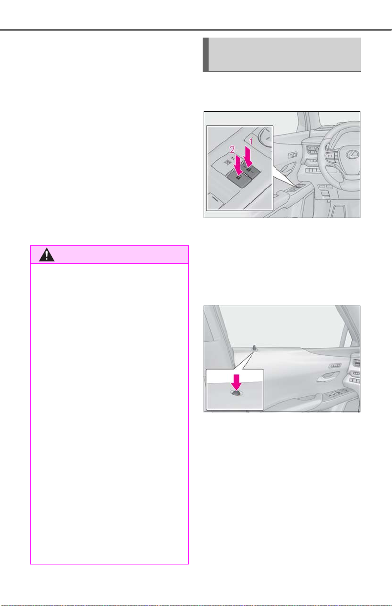
98
WARNING
3-2. Opening, closing and locking the doors
■ If the smart access system with push-
button start or the wireless remote control does not operate properly
● Use the mechanical key to lock and
unlock the doors. (P.380)
● Replace the key battery with a new one if
it is depleted. (P.341)
■ If the battery is discharged
The doors cannot be locked and unlocked
using the smart access system with pushbutton start or wireless remote control.
Lock or unlock the doors using the
mechanical key. (P.380)
■ Customization
Settings (e.g. unlocking function using a
key) can be changed. (Customizable features: P.410)
■ To prevent an accident
Observe the following precautions while
driving the vehicle.
Failure to do so may result in a door
opening and an occupant falling out,
resulting in death or serious injury.
● Ensure that all doors are properly
closed and locked.
Unlocking and locking the doors
from the inside
■ Door lock switches (to
lock/unlock)
1 Locks all the doors
2 Unlocks all the doors
■ Inside lock buttons (to lock)
Push down the inside lock button to
lock the door.
● Do not pull the inside handle of the
doors while driving.
Be especially careful for the front
doors, as the doors may be opened
even if the inside lock buttons are in
locked position.
● Set the rear door child-protector locks
when children are seated in the rear
seats.
■ When opening or closing a door
Check the surroundings of the vehicle
such as whether the vehicle is on an
incline, whether there is enough space
for a door to open and whether a strong
wind is blowing. When opening or closing the door, hold the door handle tightly
to prepare for any unpredictable movement.
■ Inside door handles (to unlock)
For the front doors
Pull the handle to unlock and open the
door.
When the door is unlocked, the inside lock
button will pop up.
For the rear doors
Pull the handle to unlock the door. Pull
the handle a second time to open the
door.
Page 99
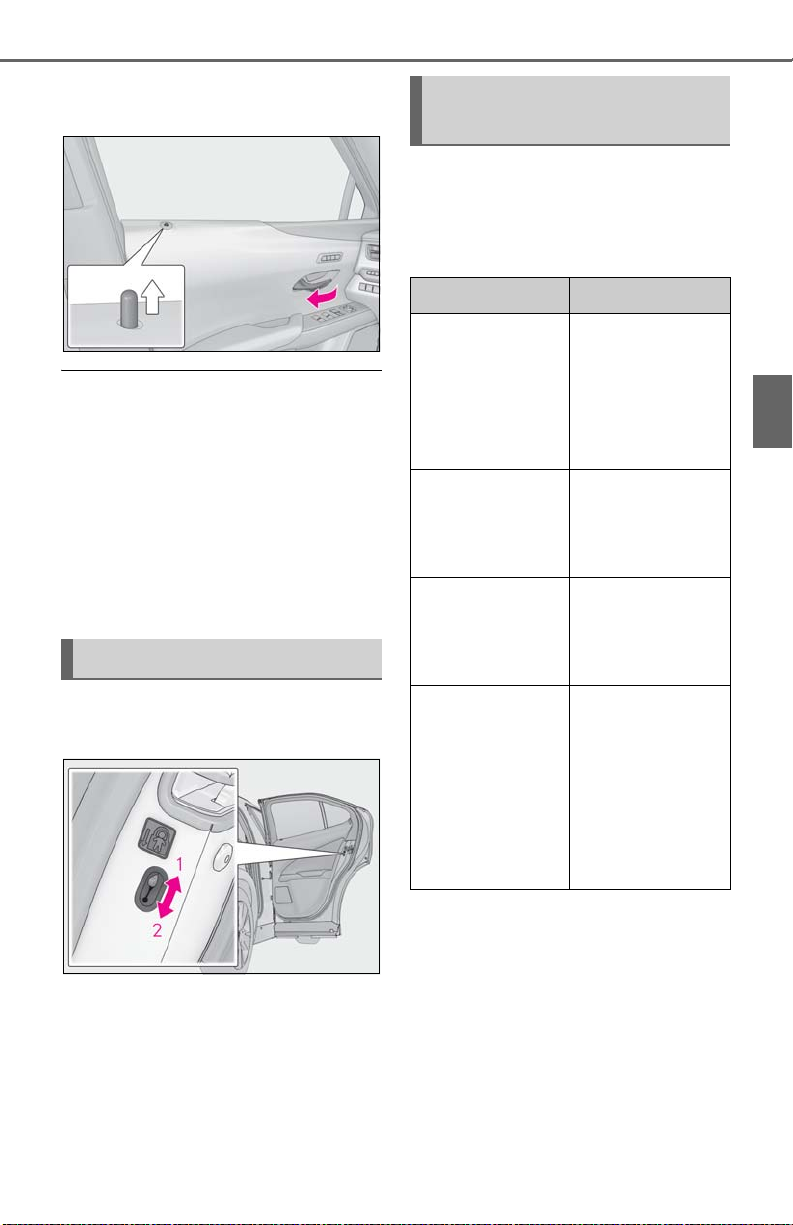
3-2. Opening, closing and locking the doors
99
When the door is unlocked, the inside lock
button will pop up.
■ If a symbol indicating one or more doors
are open is shown on the multi-information display
The hood or one or more of the doors are
not fully closed. The system also indicates
which doors are not fully closed. If the vehicle reaches a speed of 3 mph (5 km/h), a
buzzer sounds to indicate that the door(s)
are not yet fully closed.
Make sure that the hood and all the doors
are closed.
Rear door child-protector lock
Automatic door locking and
unlocking systems
The following functions can be set or
canceled:
For instructions on customizing, refer to
P.408.
Function Operation
All doors are auto-
matically locked
Speed linked door
locking function
Shift position linked
door locking function
Shift position linked
door unlocking
function
when vehicle speed
is approximately 12
mph (20 km/h) or
higher.
All doors are auto-
matically locked
when shifting the
shift lever out of P.
All doors are auto-
matically unlocked
when shifting the
shift lever to P.
3
Before driving
The door cannot be opened from
inside the vehicle when the lock is set.
1 Unlock
2 Lock
These locks can be set to prevent children
from opening the rear doors. Push down
on each rear door switch to lock both rear
doors.
Driver’s door linked
door unlocking
function
All doors are auto-
matically unlocked
when driver’s door is
opened within
approximately 45
seconds after turn-
ing the engine switch
off.
Page 100
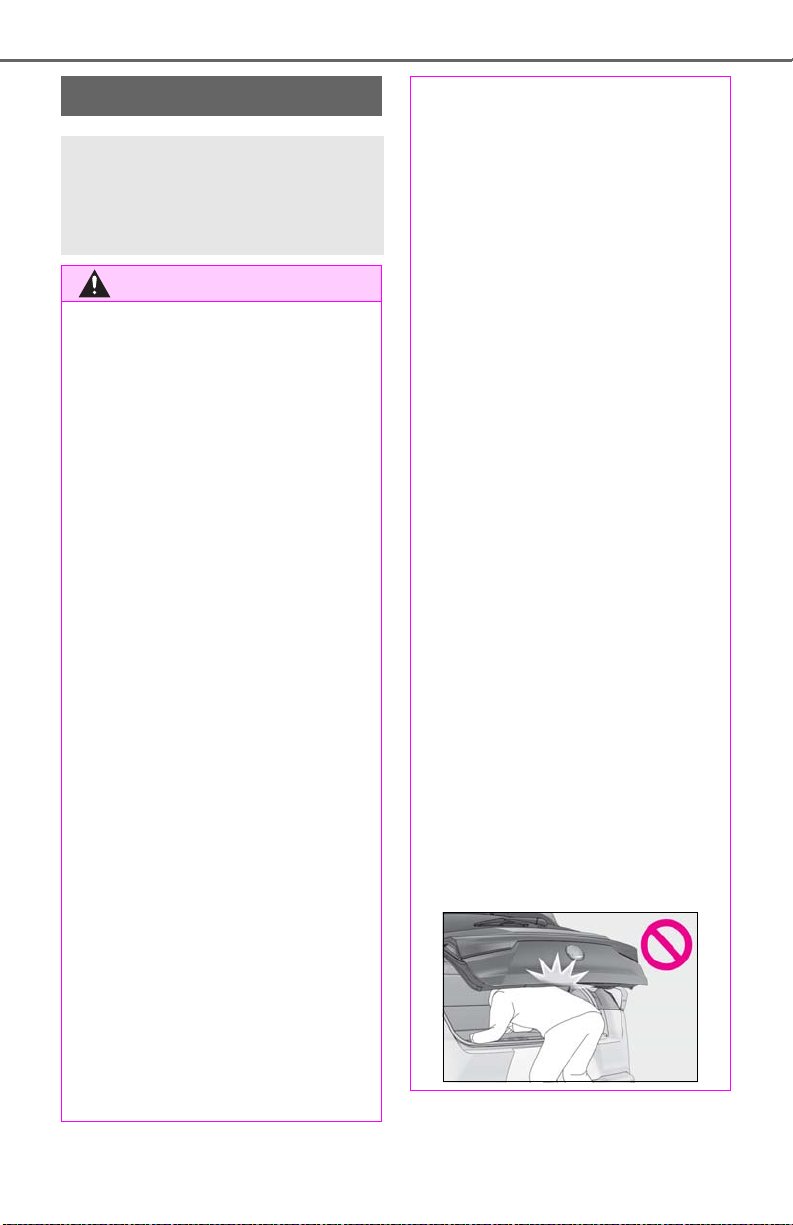
100
WARNING
3-2. Opening, closing and locking the doors
Back door
The back door can be
locked/unlocked and
opened/closed by the following
procedures.
Observe the following precautions.
Failure to do so may cause parts of the
body to be caught, resulting in death or
serious injury.
■ Before driving the vehicle
Before driving the vehicle, make sure
that the back door is fully closed. If the
back door is not fully closed, it may open
unexpectedly while driving, causing an
accident.
■ Caution while driving
● Keep the back door closed while driv-
ing.
If the back door is left open, it may hit
nearby objects while driving or luggage may be unexpectedly thrown out,
causing an accident.
In addition, exhaust gases may enter
the vehicle, causing death or a serious
health hazard. Make sure to close the
back door before driving.
● Never let anyone sit in the luggage
compartment. In the event of sudden
braking, sudden swerving or a collision, they are susceptible to death or
serious injury.
● Do not allow a child to open or close
the back door.
Doing so may cause the back door to
move unexpectedly, or cause the
child’s hands, arms, head, or neck to be
caught by the closing back door.
■ Operating the back door
Observe the following precautions.
Failure to do so may cause parts of the
body to be caught, resulting in death or
serious injury.
● Remove any heavy lo ads, such as snow
and ice, from the back door before
opening it. Failure to do so may cause
the back door to suddenly shut again
after it is opened.
● When opening or closing the back
door, thoroughly check to make sure
the surrounding area is safe.
● If anyone is in the vicinity, make sure
they are safe and let them know that
the back door is about to open or
close.
● Use caution when opening or closing
the back door in windy weather as it
may move abruptly in strong wind.
● Vehicles without power back door:
The back door may suddenly shut if it is
not opened fully. It is more difficult to
open or close the back door on an
incline than on a level surface, so
beware of the back door unexpectedly
opening or closing by itself. Make sure
that the back door is fully open and
secure before using the luggage compartment.
■ When children are in the vehicle
Observe the following precautions.
Failure to do so may result in death or
serious injury.
● Do not allow children to play in the lug-
gage compartment.
If a child is accidentally locked in the
luggage compartment, they could
have heat exhaustion or other injuries.
 Loading...