

Page 1

Edition: January 24, 2007
Lexmark™ X850e, X852e, and X854e Options
• Table of contents
• Start diagnostics
7500-XXX
• Safety and notices
• Trademarks
•Index
Lexmark and Lexmark with diamond design are
trademarks of Lexmark International, Inc., registered
in the United States and/or other countries.
Page 2

7500-XXX
Edition: January 24, 2007
The following paragraph does not apply to any country where such provisions are inconsistent with local law:
LEXMARK INTERNATIONAL, INC. PROVIDES THIS PUBLICATION “AS IS” WITHOUT WARRANTY OF ANY KIND,
EITHER EXPRESS OR IMPLIED, INCLUDING, BUT NOT LIMITED TO, THE IMPLIED WARRANTIES OF
MERCHANTABILITY OR FITNESS FOR A PARTICULAR PURPOSE. Some states do not allow disclaimer of express or
implied warranties in certain transactions; therefore, this statement may not apply to you.
This publication could include technical inaccuracies or typographical errors. Changes are periodically made to the
information herein; these changes will be incorporated in later editions. Improvements or changes in the products or the
programs described may be made at any time.
Comments may be addressed to Lexmark International, Inc., Department D22A/032-2, 740 West New Circle Road,
Lexington, Kentucky 40550, U.S.A or e-mail at ServiceInfoAndTraining@Lexmark.com. Lexmark may use or distribute any
of the information you supply in any way it believes appropriate without incurring any obligation to you. You can purchase
additional copies of publications related to this product by calling 1-800-553-9727. In other countries, contact your point of
purchase.
References in this publication to products, programs, or services do not imply that the manufacturer intends to make these
available in all countries in which it operates. Any reference to a product, program, or service is not intended to state or
imply that only that product, program, or service may be used. Any functionally equivalent product, program, or service that
does not infringe any existing intellectual property right may be used instead. Evaluation and verification of operation in
conjunction with other products, programs, or services, except those expressly designated by the manufacturer, are the
user’s responsibility.
Lexmark and Lexmark with diamond design are trademarks of Lexmark International, Inc., registered in the United States
and/or other countries.
All other trademarks are the property of their respective owners.
© 2006 Lexmark International, Inc.
All rights reserved.
UNITED STATES GOVERNMENT RIGHTS
This software and any accompanying documentation provided under this agreement are commercial computer software
and documentation developed exclusively at private expense.
P/N 12G9627
Page 3

7500-XXX
Table of contents
Safety information. . . . . . . . . . . . . . . . . . . . . . . . . . . . . . . . . . . . . . . . . . . . . . . . . . . . . . . . . . . . . . . . . . . . xiii
Preface . . . . . . . . . . . . . . . . . . . . . . . . . . . . . . . . . . . . . . . . . . . . . . . . . . . . . . . . . . . . . .xvi
Definitions . . . . . . . . . . . . . . . . . . . . . . . . . . . . . . . . . . . . . . . . . . . . . . . . . . . . . . . . . . . . . . . . . . . . . . . . . . xvi
General information . . . . . . . . . . . . . . . . . . . . . . . . . . . . . . . . . . . . . . . . . . . . . . . . . . . . . . . . . . . . . . . . . . . . 1-1
Options and features . . . . . . . . . . . . . . . . . . . . . . . . . . . . . . . . . . . . . . . . . . . . . . . . . . . . . . . . . . . . . . . . . 1-1
2X 500-Sheet drawer (2TM) . . . . . . . . . . . . . . . . . . . . . . . . . . . . . . . . . . . . . . . . . . . . . . . . . . . . . . . . . . . . 1-1
2X 500-Sheet drawer (2TM) theory . . . . . . . . . . . . . . . . . . . . . . . . . . . . . . . . . . . . . . . . . . . . . . . . . . . . . . 1-2
Driving force transmission path . . . . . . . . . . . . . . . . . . . . . . . . . . . . . . . . . . . . . . . . . . . . . . . . . . . . 1-2
Media transport . . . . . . . . . . . . . . . . . . . . . . . . . . . . . . . . . . . . . . . . . . . . . . . . . . . . . . . . . . . . . . . . . 1-3
Media transport path . . . . . . . . . . . . . . . . . . . . . . . . . . . . . . . . . . . . . . . . . . . . . . . . . . . . . . . . . . 1-3
Layout of media transport path . . . . . . . . . . . . . . . . . . . . . . . . . . . . . . . . . . . . . . . . . . . . . . . . . . 1-4
Main components associated with the media transport . . . . . . . . . . . . . . . . . . . . . . . . . . . . . . . 1-4
Functions of main components . . . . . . . . . . . . . . . . . . . . . . . . . . . . . . . . . . . . . . . . . . . . . . . . . . 1-4
Media tray assembly . . . . . . . . . . . . . . . . . . . . . . . . . . . . . . . . . . . . . . . . . . . . . . . . . . . . . . . . . . . . . 1-5
Front media tray guide and rear media tray guide . . . . . . . . . . . . . . . . . . . . . . . . . . . . . . . . . . . 1-5
Media tray end guide . . . . . . . . . . . . . . . . . . . . . . . . . . . . . . . . . . . . . . . . . . . . . . . . . . . . . . . . . . 1-5
Bottom plate . . . . . . . . . . . . . . . . . . . . . . . . . . . . . . . . . . . . . . . . . . . . . . . . . . . . . . . . . . . . . . . . 1-5
Media feed unit assembly . . . . . . . . . . . . . . . . . . . . . . . . . . . . . . . . . . . . . . . . . . . . . . . . . . . . . . 1-5
Media feed lift motor . . . . . . . . . . . . . . . . . . . . . . . . . . . . . . . . . . . . . . . . . . . . . . . . . . . . . . . . . . 1-5
Switch (media size) . . . . . . . . . . . . . . . . . . . . . . . . . . . . . . . . . . . . . . . . . . . . . . . . . . . . . . . . . . . 1-5
Sensor (media out) . . . . . . . . . . . . . . . . . . . . . . . . . . . . . . . . . . . . . . . . . . . . . . . . . . . . . . . . . . . 1-5
Sensor (media level) . . . . . . . . . . . . . . . . . . . . . . . . . . . . . . . . . . . . . . . . . . . . . . . . . . . . . . . . . . 1-5
Sensor (pre-feed) . . . . . . . . . . . . . . . . . . . . . . . . . . . . . . . . . . . . . . . . . . . . . . . . . . . . . . . . . . . . 1-6
Main components . . . . . . . . . . . . . . . . . . . . . . . . . . . . . . . . . . . . . . . . . . . . . . . . . . . . . . . . . . . . . . . 1-7
Switch (2TM/TTM left door interlock) . . . . . . . . . . . . . . . . . . . . . . . . . . . . . . . . . . . . . . . . . . . . . 1-7
Sensor (tray 3 feed-out) . . . . . . . . . . . . . . . . . . . . . . . . . . . . . . . . . . . . . . . . . . . . . . . . . . . . . . . 1-7
Sensor (tray 4 feed-out) . . . . . . . . . . . . . . . . . . . . . . . . . . . . . . . . . . . . . . . . . . . . . . . . . . . . . . . 1-7
2TM/TTM Transport roll assembly . . . . . . . . . . . . . . . . . . . . . . . . . . . . . . . . . . . . . . . . . . . . . . . 1-7
2TM/TTM controller card assembly . . . . . . . . . . . . . . . . . . . . . . . . . . . . . . . . . . . . . . . . . . . . . . . 1-7
Switch (media size) . . . . . . . . . . . . . . . . . . . . . . . . . . . . . . . . . . . . . . . . . . . . . . . . . . . . . . . . . . . 1-8
High capacity feeder . . . . . . . . . . . . . . . . . . . . . . . . . . . . . . . . . . . . . . . . . . . . . . . . . . . . . . . . . . . . . . . . . 1-9
Media feeding . . . . . . . . . . . . . . . . . . . . . . . . . . . . . . . . . . . . . . . . . . . . . . . . . . . . . . . . . . . . . . . . . . 1-10
Outline . . . . . . . . . . . . . . . . . . . . . . . . . . . . . . . . . . . . . . . . . . . . . . . . . . . . . . . . . . . . . . . . . . . . 1-10
HCF media feed unit assembly . . . . . . . . . . . . . . . . . . . . . . . . . . . . . . . . . . . . . . . . . . . . . . . . . 1-10
HCF media transport roll assembly . . . . . . . . . . . . . . . . . . . . . . . . . . . . . . . . . . . . . . . . . . . . . . 1-10
HCF media feed unit assembly operation . . . . . . . . . . . . . . . . . . . . . . . . . . . . . . . . . . . . . . . . . . . 1-12
HCF media transport roll assembly operation . . . . . . . . . . . . . . . . . . . . . . . . . . . . . . . . . . . . . . . 1-13
HCF media feed unit assembly sensor/motor functions . . . . . . . . . . . . . . . . . . . . . . . . . . . . . . . 1-14
Status monitoring . . . . . . . . . . . . . . . . . . . . . . . . . . . . . . . . . . . . . . . . . . . . . . . . . . . . . . . . . . . . . . 1-15
Static media jam detection . . . . . . . . . . . . . . . . . . . . . . . . . . . . . . . . . . . . . . . . . . . . . . . . . . . . 1-15
Interlock detection . . . . . . . . . . . . . . . . . . . . . . . . . . . . . . . . . . . . . . . . . . . . . . . . . . . . . . . . . . . 1-15
Tray insertion detection . . . . . . . . . . . . . . . . . . . . . . . . . . . . . . . . . . . . . . . . . . . . . . . . . . . . . . . 1-16
Functions of sensors used for status monitoring . . . . . . . . . . . . . . . . . . . . . . . . . . . . . . . . . . . . 1-16
Media size detection . . . . . . . . . . . . . . . . . . . . . . . . . . . . . . . . . . . . . . . . . . . . . . . . . . . . . . . . . 1-17
Sensor for media size detection . . . . . . . . . . . . . . . . . . . . . . . . . . . . . . . . . . . . . . . . . . . . . . . . 1-17
Size sensors . . . . . . . . . . . . . . . . . . . . . . . . . . . . . . . . . . . . . . . . . . . . . . . . . . . . . . . . . . . . . . . 1-17
Tray lifting . . . . . . . . . . . . . . . . . . . . . . . . . . . . . . . . . . . . . . . . . . . . . . . . . . . . . . . . . . . . . . . . . 1-18
Media out detection . . . . . . . . . . . . . . . . . . . . . . . . . . . . . . . . . . . . . . . . . . . . . . . . . . . . . . . . . . 1-18
Sensor (media out) . . . . . . . . . . . . . . . . . . . . . . . . . . . . . . . . . . . . . . . . . . . . . . . . . . . . . . . . . . 1-19
Remaining media volume detection . . . . . . . . . . . . . . . . . . . . . . . . . . . . . . . . . . . . . . . . . . . . . 1-1
Sensor (media level) . . . . . . . . . . . . . . . . . . . . . . . . . . . . . . . . . . . . . . . . . . . . . . . . . . . . . . . . . 1-20
Finisher . . . . . . . . . . . . . . . . . . . . . . . . . . . . . . . . . . . . . . . . . . . . . . . . . . . . . . . . . . . . . . . . . . . . . . . . . . . 1-21
Finisher weight . . . . . . . . . . . . . . . . . . . . . . . . . . . . . . . . . . . . . . . . . . . . . . . . . . . . . . . . . . . . . . . . 1-21
Components . . . . . . . . . . . . . . . . . . . . . . . . . . . . . . . . . . . . . . . . . . . . . . . . . . . . . . . . . . . . . . . . . . . 1-21
9
Table of contents iii
Page 4

7500-XXX
Stacker media bin block to stack media . . . . . . . . . . . . . . . . . . . . . . . . . . . . . . . . . . . . . . . . . . . . .1-22
Media size and weight . . . . . . . . . . . . . . . . . . . . . . . . . . . . . . . . . . . . . . . . . . . . . . . . . . . . . . . . . . .1-22
Media size/orientation and applicable functions . . . . . . . . . . . . . . . . . . . . . . . . . . . . . . . . . . . . .1-23
Media weight . . . . . . . . . . . . . . . . . . . . . . . . . . . . . . . . . . . . . . . . . . . . . . . . . . . . . . . . . . . . . . .1-23
Features . . . . . . . . . . . . . . . . . . . . . . . . . . . . . . . . . . . . . . . . . . . . . . . . . . . . . . . . . . . . . . . . . . . . . . .1-24
Finisher theory . . . . . . . . . . . . . . . . . . . . . . . . . . . . . . . . . . . . . . . . . . . . . . . . . . . . . . . . . . . . . . . . . . . . . .1-24
Media transport . . . . . . . . . . . . . . . . . . . . . . . . . . . . . . . . . . . . . . . . . . . . . . . . . . . . . . . . . . . . . . . . .1-24
Bridge unit assembly paper path . . . . . . . . . . . . . . . . . . . . . . . . . . . . . . . . . . . . . . . . . . . . . . . .1-24
Finisher media path . . . . . . . . . . . . . . . . . . . . . . . . . . . . . . . . . . . . . . . . . . . . . . . . . . . . . . . . . .1-24
Finisher roll assemblies . . . . . . . . . . . . . . . . . . . . . . . . . . . . . . . . . . . . . . . . . . . . . . . . . . . . . . .1-25
Finisher media path sensors . . . . . . . . . . . . . . . . . . . . . . . . . . . . . . . . . . . . . . . . . . . . . . . . . . .1-25
Finisher motors . . . . . . . . . . . . . . . . . . . . . . . . . . . . . . . . . . . . . . . . . . . . . . . . . . . . . . . . . . . . . .1-26
Bridge unit assembly . . . . . . . . . . . . . . . . . . . . . . . . . . . . . . . . . . . . . . . . . . . . . . . . . . . . . . . . .1-26
From bridge unit assembly to punch . . . . . . . . . . . . . . . . . . . . . . . . . . . . . . . . . . . . . . . . . . . . .1-27
From punch to compiler unit assembly . . . . . . . . . . . . . . . . . . . . . . . . . . . . . . . . . . . . . . . . . . . .1-28
From compiler unit assembly to stacker media bin . . . . . . . . . . . . . . . . . . . . . . . . . . . . . . . . . .1-30
From punch to upper media bin . . . . . . . . . . . . . . . . . . . . . . . . . . . . . . . . . . . . . . . . . . . . . . . . .1-30
Functions of sensors along the media path . . . . . . . . . . . . . . . . . . . . . . . . . . . . . . . . . . . . . . . . . .1-30
Bridge unit assembly . . . . . . . . . . . . . . . . . . . . . . . . . . . . . . . . . . . . . . . . . . . . . . . . . . . . . . . . .1-30
Finisher . . . . . . . . . . . . . . . . . . . . . . . . . . . . . . . . . . . . . . . . . . . . . . . . . . . . . . . . . . . . . . . . . . . .1-31
Punch unit . . . . . . . . . . . . . . . . . . . . . . . . . . . . . . . . . . . . . . . . . . . . . . . . . . . . . . . . . . . . . . . . . . . . .1-32
Adjusting punching positions . . . . . . . . . . . . . . . . . . . . . . . . . . . . . . . . . . . . . . . . . . . . . . . . . . .1-32
Punching . . . . . . . . . . . . . . . . . . . . . . . . . . . . . . . . . . . . . . . . . . . . . . . . . . . . . . . . . . . . . . . . . .1-33
Detecting punch waste full . . . . . . . . . . . . . . . . . . . . . . . . . . . . . . . . . . . . . . . . . . . . . . . . . . . . .1-34
Detecting punch waste box . . . . . . . . . . . . . . . . . . . . . . . . . . . . . . . . . . . . . . . . . . . . . . . . . . . .1-34
Functions of punch sensors/motors . . . . . . . . . . . . . . . . . . . . . . . . . . . . . . . . . . . . . . . . . . . . . .1-34
Compiler unit assembly . . . . . . . . . . . . . . . . . . . . . . . . . . . . . . . . . . . . . . . . . . . . . . . . . . . . . . . . . .1-35
Outline of operation . . . . . . . . . . . . . . . . . . . . . . . . . . . . . . . . . . . . . . . . . . . . . . . . . . . . . . . . . .1-35
Capacity of compiler unit assembly . . . . . . . . . . . . . . . . . . . . . . . . . . . . . . . . . . . . . . . . . . . . . .1-36
Compiler unit assembly operation with multiple media sizes . . . . . . . . . . . . . . . . . . . . . . . . . . .1-36
Tamping . . . . . . . . . . . . . . . . . . . . . . . . . . . . . . . . . . . . . . . . . . . . . . . . . . . . . . . . . . . . . . . . . . .1-36
Front tamping . . . . . . . . . . . . . . . . . . . . . . . . . . . . . . . . . . . . . . . . . . . . . . . . . . . . . . . . . . . . . . .1-37
Rear tamping . . . . . . . . . . . . . . . . . . . . . . . . . . . . . . . . . . . . . . . . . . . . . . . . . . . . . . . . . . . . . . .1-38
Center tamping . . . . . . . . . . . . . . . . . . . . . . . . . . . . . . . . . . . . . . . . . . . . . . . . . . . . . . . . . . . . . .1-39
Determining tamper home position . . . . . . . . . . . . . . . . . . . . . . . . . . . . . . . . . . . . . . . . . . . . . .1-39
Tamping . . . . . . . . . . . . . . . . . . . . . . . . . . . . . . . . . . . . . . . . . . . . . . . . . . . . . . . . . . . . . . . . . . .1-39
Offsetting . . . . . . . . . . . . . . . . . . . . . . . . . . . . . . . . . . . . . . . . . . . . . . . . . . . . . . . . . . . . . . . . . .1-40
Functions of compiler unit assembly sensors/motors . . . . . . . . . . . . . . . . . . . . . . . . . . . . . . . . .1-40
Stapler . . . . . . . . . . . . . . . . . . . . . . . . . . . . . . . . . . . . . . . . . . . . . . . . . . . . . . . . . . . . . . . . . . . . . . . .1-41
Stapling operation . . . . . . . . . . . . . . . . . . . . . . . . . . . . . . . . . . . . . . . . . . . . . . . . . . . . . . . . . . .1-41
Staple positions . . . . . . . . . . . . . . . . . . . . . . . . . . . . . . . . . . . . . . . . . . . . . . . . . . . . . . . . . . . . .1-41
Media sizes that allow stapling . . . . . . . . . . . . . . . . . . . . . . . . . . . . . . . . . . . . . . . . . . . . . . . . . .1-42
Stapling one sheet . . . . . . . . . . . . . . . . . . . . . . . . . . . . . . . . . . . . . . . . . . . . . . . . . . . . . . . . . . .1-42
Stapling multiple size media . . . . . . . . . . . . . . . . . . . . . . . . . . . . . . . . . . . . . . . . . . . . . . . . . . . .1-43
Media limits for stapling . . . . . . . . . . . . . . . . . . . . . . . . . . . . . . . . . . . . . . . . . . . . . . . . . .
Stapler operation . . . . . . . . . . . . . . . . . . . . . . . . . . . . . . . . . . . . . . . . . . . . . . . . . . . . . . . . . . . .1-43
Stapler unit assembly . . . . . . . . . . . . . . . . . . . . . . . . . . . . . . . . . . . . . . . . . . . . . . . . . . . . . . . . .1-44
Functions of stapler sensors/motors . . . . . . . . . . . . . . . . . . . . . . . . . . . . . . . . . . . . . . . . . . . . .1-44
Upper media bin . . . . . . . . . . . . . . . . . . . . . . . . . . . . . . . . . . . . . . . . . . . . . . . . . . . . . . . . . . . . . . . .1-45
Operation . . . . . . . . . . . . . . . . . . . . . . . . . . . . . . . . . . . . . . . . . . . . . . . . . . . . . . . . . . . . . . . . . .1-45
Functions of upper media bin sensors . . . . . . . . . . . . . . . . . . . . . . . . . . . . . . . . . . . . . . . . . . . .1-45
Stacker media bin . . . . . . . . . . . . . . . . . . . . . . . . . . . . . . . . . . . . . . . . . . . . . . . . . . . . . . . . . . . . . . .1-46
Operation . . . . . . . . . . . . . . . . . . . . . . . . . . . . . . . . . . . . . . . . . . . . . . . . . . . . . . . . . . . . . . . . . .1-46
Full stack detection . . . . . . . . . . . . . . . . . . . . . . . . . . . . . . . . . . . . . . . . . . . . . . . . . . . . . . . . . . .1-48
Functions of stacker media bin sensors/motors . . . . . . . . . . . . . . . . . . . . . . . . . . . . . . . . . . . . .1-48
Power supply and interlock . . . . . . . . . . . . . . . . . . . . . . . . . . . . . . . . . . . . . . . . . . . . . . . . . . . . . . .1-50
Tools required for service . . . . . . . . . . . . . . . . . . . . . . . . . . . . . . . . . . . . . . . . . . . . . . . . . . . . . . . . . . . .1-51
Acronyms . . . . . . . . . . . . . . . . . . . . . . . . . . . . . . . . . . . . . . . . . . . . . . . . . . . . . . . . . . . . . . . . . . . . . . . . . .1-51
. . . . .1-43
Diagnostic information. . . . . . . . . . . . . . . . . . . . . . . . . . . . . . . . . . . . . . . . . . . . . . . . . . . . . . . . . . . . . . . . . 2-1
iv Options Service Manual
Page 5

7500-XXX
Start . . . . . . . . . . . . . . . . . . . . . . . . . . . . . . . . . . . . . . . . . . . . . . . . . . . . . . . . . . . . . . . . . . . . . . . . . . . . . . . 2-1
Using service checks . . . . . . . . . . . . . . . . . . . . . . . . . . . . . . . . . . . . . . . . . . . . . . . . . . . . . . . . . . . . 2-1
Confirm the installation status . . . . . . . . . . . . . . . . . . . . . . . . . . . . . . . . . . . . . . . . . . . . . . . . . . . . . . . . . 2-2
Power-on Reset sequence . . . . . . . . . . . . . . . . . . . . . . . . . . . . . . . . . . . . . . . . . . . . . . . . . . . . . . . . . . . . . 2-2
Error code messages - 2X 500-sheet drawer (2TM) . . . . . . . . . . . . . . . . . . . . . . . . . . . . . . . . . . . . . . . . 2-3
Service checks - 2X 500-sheet drawer (2TM) . . . . . . . . . . . . . . . . . . . . . . . . . . . . . . . . . . . . . . . . . . . . . . 2-5
243.00 Sensor (pre-feed) on jam (tray 3 media feed) . . . . . . . . . . . . . . . . . . . . . . . . . . . . . . . . . . . 2-5
243.01 Sensor (tray 3 feed-out) on jam (tray 3 media feed) . . . . . . . . . . . . . . . . . . . . . . . . . . . . . . 2-6
243.02 Sensor (tray 2 feed-out) on jam (tray 3 media feed) . . . . . . . . . . . . . . . . . . . . . . . . . . . . . . 2-8
243.03 Sensor (registration) on jam (tray 3 media feed) . . . . . . . . . . . . . . . . . . . . . . . . . . . . . . . 2-10
243.04 Sensor (tray 3 feed-out) static jam . . . . . . . . . . . . . . . . . . . . . . . . . . . . . . . . . . . . . . . . . . 2-12
244.00 Sensor (tray 4 feed-out) on jam (tray 4 media feed) . . . . . . . . . . . . . . . . . . . . . . . . . . . . . 2-13
244.01 Sensor (tray 3 feed-out) on jam (tray 4 media feed) . . . . . . . . . . . . . . . . . . . . . . . . . . . . . 2-14
244.02 Sensor (tray 2 feed-out) on jam (tray 4 media feed) . . . . . . . . . . . . . . . . . . . . . . . . . . . . . 2-16
244.03 Sensor (registration) on jam (tray 4 media feed) . . . . . . . . . . . . . . . . . . . . . . . . . . . . . . . 2-18
244.04 Sensor (pre-feed) on jam (tray 4 media feed) . . . . . . . . . . . . . . . . . . . . . . . . . . . . . . . . . . 2-20
244.05 Sensor (tray 4 feed-out) static jam . . . . . . . . . . . . . . . . . . . . . . . . . . . . . . . . . . . . . . . . . . 2-22
943.00 Tray 3 lift up / no tray failure . . . . . . . . . . . . . . . . . . . . . . . . . . . . . . . . . . . . . . . . . . . . . . . . 2-23
944.00 Tray 4 lift up / no tray failure . . . . . . . . . . . . . . . . . . . . . . . . . . . . . . . . . . . . . . . . . . . . . . . . 2-24
980.00 2TM/TTM controller card assembly communication failure . . . . . . . . . . . . . . . . . . . . . . 2-26
Tray 3 media size failure . . . . . . . . . . . . . . . . . . . . . . . . . . . . . . . . . . . . . . . . . . . . . . . . . . . . . . . . . 2-26
Tray 4 media size failure . . . . . . . . . . . . . . . . . . . . . . . . . . . . . . . . . . . . . . . . . . . . . . . . . . . . . . . . . 2-27
2TM/TTM left door assembly open . . . . . . . . . . . . . . . . . . . . . . . . . . . . . . . . . . . . . . . . . . . . . . . . . 2-28
No media in the select media tray . . . . . . . . . . . . . . . . . . . . . . . . . . . . . . . . . . . . . . . . . . . . . . . . . 2-29
Media size mismatch in width . . . . . . . . . . . . . . . . . . . . . . . . . . . . . . . . . . . . . . . . . . . . . . . . . . . . 2-30
Tray 3 media size mismatch in length . . . . . . . . . . . . . . . . . . . . . . . . . . . . . . . . . . . . . . . . . . . . . . 2-31
Tray 4 media size mismatch in length . . . . . . . . . . . . . . . . . . . . . . . . . . . . . . . . . . . . . . . . . . . . . . 2-33
Error code messages - HCF . . . . . . . . . . . . . . . . . . . . . . . . . . . . . . . . . . . . . . . . . . . . . . . . . . . . . . . . . . 2-36
Service checks - HCF . . . . . . . . . . . . . . . . . . . . . . . . . . . . . . . . . . . . . . . . . . . . . . . . . . . . . . . . . . . . . . . . 2-37
245.00 Sensor (tray 5 feed-out) on jam . . . . . . . . . . . . . . . . . . . . . . . . . . . . . . . . . . . . . . . . . . . . . 2-37
245.01 Sensor (tray 2 feed-out) on jam . . . . . . . . . . . . . . . . . . . . . . . . . . . . . . . . . . . . . . . . . . . . . 2-39
245.02 Sensor (registration) on jam . . . . . . . . . . . . . . . . . . . . . . . . . . . . . . . . . . . . . . . . . . . . . . . . 2-40
245.03 Sensor (tray 5 feed-out) static jam . . . . . . . . . . . . . . . . . . . . . . . . . . . . . . . . . . . . . . . . . . . 2-42
945.00 HCF unit media tray lift failure . . . . . . . . . . . . . . . . . . . . . . . . . . . . . . . . . . . . . . . . . . . . . . 2-44
945.01 HCF unit NVM R/W failure . . . . . . . . . . . . . . . . . . . . . . . . . . . . . . . . . . . . . . . . . . . . . . . . . . 2-45
980.01 Tray 5 HCF communication failure . . . . . . . . . . . . . . . . . . . . . . . . . . . . . . . . . . . . . . . . . . 2-45
HCF top door assembly open . . . . . . . . . . . . . . . . . . . . . . . . . . . . . . . . . . . . . . . . . . . . . . . . . . . . . 2-46
HCF unit docking failure or tray 5 set failure . . . . . . . . . . . . . . . . . . . . . . . . . . . . . . . . . . . . . . . . 2-47
No media in the selected media tray . . . . . . . . . . . . . . . . . . . . . . . . . . . . . . . . . . . . . . . . . . . . . . . 2-48
Error code messages - finisher . . . . . . . . . . . . . . . . . . . . . . . . . . . . . . . . . . . . . . . . . . . . . . . . . . . . . . . . 2-50
Service checks - finisher . . . . . . . . . . . . . . . . . . . . . . . . . . . . . . . . . . . . . . . . . . . . . . . . . . . . . . . . . . . . . 2-58
280.00 Sensor (bridge unit media entrance) on Jam . . . . . . . . . . . . . . . . . . . . . . . . . . . . . . . . . . 2-58
280.01 Sensor (bridge unit media entrance) static jam A . . . . . . . . . . . . . . . . . . . . . . . . . . . . . . 2-59
280.02 Sensor (bridge unit media entrance) static jam B . . . . . . . . . . . . . . . . . . . . . . . . . . . . . . 2-60
281.00 Sensor (bridge unit media exit) On Jam A . . . . . . . . . . . . . . . . . . . . . . . . . . . . . . . . . . . . 2-62
281.01 Sensor (bridge unit media exit) On Jam B . . . . . . . . . . . . . . . . . . . . . . . . . . . . . . . . . . . . 2-63
281.02 Sensor (bridge unit media exit) On Jam C . . . . . . . . . . . . . . . . . . . . . . . . . . . . . . . . . . . . 2-65
281.03 Sensor (bridge unit media exit) static jam A . . . . . . . . . . . . . . . . . . . . . . . . . . . . . . . . . . . 2-66
282.00 Sensor (finisher media entrance) on jam . . . . . . . . . . . . . . . . . . . . . . . . . . . . . . . . . . . . . 2-67
282.01 Sensor (finisher media entrance) static jam A . . . . . . . . . . . . . . . . . . . . . . . . . . . . . . . . . 2-69
283.00 Sensor (buffer path) on jam A . . . . . . . . . . . . . . . . . . . . . . . . . . . . . . . . . . . . . . . . . . . . . . 2-70
283.01 Sensor (buffer path) on jam B . . . . . . . . . . . . . . . . . . . . . . . . . . . . . . . . . . . . . . . . . . . . . . 2-74
283.02 Sensor (buffer path) static jam A . . . . . . . . . . . . . . . . . . . . . . . . . . . . . . . . . . . . . . . . . . . . 2-77
283.03 Sensor (buffer path) static jam B . . . . . . . . . . . . . . . . . . . . . . . . . . . . . . . . . . . . . . . . . . . . 2-78
283.04 Sensor (buffer path) static jam C . . . . . . . . . . . . . . . . . . . . . . . . . . . . . . . . . . . . . . . . . . . . 2-79
284.00 Sensor (lower media exit) off jam A. . . . . . . . . . . . . . . . . . . . . . . . . . . . . . . . . . . . . . . . . . 2-80
284.01 Sensor (lower media exit) on jam A . . . . . . . . . . . . . . . . . . . . . . . . . . . . . . . . . . . . . . . . . . 2
284.02 Sensor (lower media exit) on jam B . . . . . . . . . . . . . . . . . . . . . . . . . . . . . . . . . . . . . . . . . . 2-83
284.03 Sensor (lower media exit) on jam C . . . . . . . . . . . . . . . . . . . . . . . . . . . . . . . . . . . . . . . . . . 2-86
-81
Table of contents v
Page 6

7500-XXX
284.04 Sensor (lower media exit) off jam B. . . . . . . . . . . . . . . . . . . . . . . . . . . . . . . . . . . . . . . . . . .2-88
284.05 Sensor (lower media exit) static jam . . . . . . . . . . . . . . . . . . . . . . . . . . . . . . . . . . . . . . . . . .2-90
285.00 Finisher eject set jam . . . . . . . . . . . . . . . . . . . . . . . . . . . . . . . . . . . . . . . . . . . . . . . . . . . . . .2-92
286.00 Sensor (compiler media in) static jam . . . . . . . . . . . . . . . . . . . . . . . . . . . . . . . . . . . . . . . .2-93
287.00 Sensor (upper media exit) on jam A . . . . . . . . . . . . . . . . . . . . . . . . . . . . . . . . . . . . . . . . . .2-94
287.01 Sensor (upper media exit) off jam A. . . . . . . . . . . . . . . . . . . . . . . . . . . . . . . . . . . . . . . . . .2-96
287.02 Sensor (upper media exit) on jam B . . . . . . . . . . . . . . . . . . . . . . . . . . . . . . . . . . . . . . . . . .2-98
287.03 Sensor (upper media exit) on jam C . . . . . . . . . . . . . . . . . . . . . . . . . . . . . . . . . . . . . . . . .2-100
287.04 Sensor (upper media exit) off jam B. . . . . . . . . . . . . . . . . . . . . . . . . . . . . . . . . . . . . . . . .2-101
287.05 Sensor (upper media exit) static jam A . . . . . . . . . . . . . . . . . . . . . . . . . . . . . . . . . . . . . . .2-103
287.06 Sensor (upper media exit) static jam B . . . . . . . . . . . . . . . . . . . . . . . . . . . . . . . . . . . . . . .2-105
287.07 Sensor (upper media exit) static jam C . . . . . . . . . . . . . . . . . . . . . . . . . . . . . . . . . . . . . . .2-106
288.00 Sensor (diverter gate) on jam . . . . . . . . . . . . . . . . . . . . . . . . . . . . . . . . . . . . . . . . . . . . . .2-107
288.01 Sensor (diverter gate) static jam (to top bin) A . . . . . . . . . . . . . . . . . . . . . . . . . . . . . . . .2-110
288.02 Sensor (diverter gate) static jam (to top bin) B . . . . . . . . . . . . . . . . . . . . . . . . . . . . . . . .2-111
288.03 Sensor (diverter gate) static jam (to top bin) C . . . . . . . . . . . . . . . . . . . . . . . . . . . . . . . .2-112
288.04 Sensor (diverter gate) static jam (to stacker bin) A . . . . . . . . . . . . . . . . . . . . . . . . . . . . .2-113
288.05 Sensor (diverter gate) static jam (to stacker bin) B . . . . . . . . . . . . . . . . . . . . . . . . . . . . .2-115
288.06 Sensor (diverter gate) static jam (to stacker bin) C . . . . . . . . . . . . . . . . . . . . . . . . . . . . .2-116
980.02 Finisher communication failure . . . . . . . . . . . . . . . . . . . . . . . . . . . . . . . . . . . . . . . . . . . . .2-117
981.00 Stacker bin failure . . . . . . . . . . . . . . . . . . . . . . . . . . . . . . . . . . . . . . . . . . . . . . . . . . . . . . . .2-118
981.01 Stacker bin upper limit failure . . . . . . . . . . . . . . . . . . . . . . . . . . . . . . . . . . . . . . . . . . . . . .2-119
981.02 Stacker bin lower limit failure . . . . . . . . . . . . . . . . . . . . . . . . . . . . . . . . . . . . . . . . . . . . . .2-121
982.00 Sensor (front tamper HP) on failure . . . . . . . . . . . . . . . . . . . . . . . . . . . . . . . . . . . . . . . . .2-124
982.01 Sensor (front tamper HP) off failure . . . . . . . . . . . . . . . . . . . . . . . . . . . . . . . . . . . . . . . . .2-125
983.00 Sensor (rear tamper HP) on failure . . . . . . . . . . . . . . . . . . . . . . . . . . . . . . . . . . . . . . . . . .2-126
983.01 Sensor (rear tamper HP) off failure . . . . . . . . . . . . . . . . . . . . . . . . . . . . . . . . . . . . . . . . . .2-128
984.00 Sensor (punch unit HP) on failure . . . . . . . . . . . . . . . . . . . . . . . . . . . . . . . . . . . . . . . . . . .2-129
984.01 Sensor (punch unit HP) off failure . . . . . . . . . . . . . . . . . . . . . . . . . . . . . . . . . . . . . . . . . . .2-130
985.00 Sensor (punch carriage shift HP) on failure . . . . . . . . . . . . . . . . . . . . . . . . . . . . . . . . . . .2-131
985.01 Sensor (punch carriage shift HP) off failure . . . . . . . . . . . . . . . . . . . . . . . . . . . . . . . . . . .2-133
986.00 Sensor (media eject clamp HP) on failure . . . . . . . . . . . . . . . . . . . . . . . . . . . . . . . . . . . .2-134
986.01 Sensor (media eject clamp HP) off failure . . . . . . . . . . . . . . . . . . . . . . . . . . . . . . . . . . . .2-135
987.00 Sensor (media eject shaft HP) on failure . . . . . . . . . . . . . . . . . . . . . . . . . . . . . . . . . . . . .2-136
987.01 Sensor (media eject shaft HP) off failure . . . . . . . . . . . . . . . . . . . . . . . . . . . . . . . . . . . . .2-138
988.00 Sensor (punch unit side reg) on failure . . . . . . . . . . . . . . . . . . . . . . . . . . . . . . . . . . . . . .2-139
988.01 Sensor (punch unit side reg) off failure . . . . . . . . . . . . . . . . . . . . . . . . . . . . . . . . . . . . . .2-141
989.00 Stapler unit failure . . . . . . . . . . . . . . . . . . . . . . . . . . . . . . . . . . . . . . . . . . . . . . . . . . . . . . .2-143
990.00 Sensor (stapler carriage HP) on failure . . . . . . . . . . . . . . . . . . . . . . . . . . . . . . . . . . . . . .2-144
990.01 Sensor (stapler carriage HP) off failure . . . . . . . . . . . . . . . . . . . . . . . . . . . . . . . . . . . . . .2-145
995.00 Finisher NVRAM R/W failure . . . . . . . . . . . . . . . . . . . . . . . . . . . . . . . . . . . . . . . . . . . . . . .2-146
996.00 Finisher type failure . . . . . . . . . . . . . . . . . . . . . . . . . . . . . . . . . . . . . . . . . . . . . . . . . . . . . .2-146
999.00 Finisher engine/RIP functional failure . . . . . . . . . . . . . . . . . . . . . . . . . . . . . . . . . . . . . . .2-146
Bridge unit top cover open . . . . . . . . . . . . . . . . . . . . . . . . . . . . . . . . . . . . . . . . . . . . . . . . . . . . . .2-147
Finisher front door open . . . . . . . . . . . . . . . . . . . . . . . . . . . . . . . . . . . . . . . . . . . . . . . . . . . . . . . .2-149
Finisher eject cover open . . . . . . . . . . . . . . . . . . . . . . . . . . . . . . . . . . . . . . . . . . . . . . . . . . . . . . . .2-150
Finisher upper media bin full . . . . . . . . . . . . . . . . . . . . . . . . . . . . . . . . . . . . . . . . . . . . . . . . . . . . .2-150
No punch waste box. . . . . . . . . . . . . . . . . . . . . . . . . . . . . . . . . . . . . . . . . . . . . . . . . . . . . . . . . . . .2-151
Punch waste box full . . . . . . . . . . . . . . . . . . . . . . . . . . . . . . . . . . . . . . . . . . . . . . . . . . . . . . . . . . .2-152
Stacker media bin full (mix size) . . . . . . . . . . . . . . . . . . . . . . . . . . . . . . . . . . . . . . . . . . . . . . .
Stacker media bin full (no mix) . . . . . . . . . . . . . . . . . . . . . . . . . . . . . . . . . . . . . . . . . . . . . . . . . . .2-155
Stacker lower safety failure . . . . . . . . . . . . . . . . . . . . . . . . . . . . . . . . . . . . . . . . . . . . . . . . . . . . . .2-157
Stacker set over count failure . . . . . . . . . . . . . . . . . . . . . . . . . . . . . . . . . . . . . . . . . . . . . . . . . . . .2-158
Staple cartridge empty . . . . . . . . . . . . . . . . . . . . . . . . . . . . . . . . . . . . . . . . . . . . . . . . . . . . . . . . . .2-159
. . .2-153
Diagnostic aids . . . . . . . . . . . . . . . . . . . . . . . . . . . . . . . . . . . . . . . . . . . . . . . . . . . . . . . . . . . . . . . . . . . . . . . . . 3-1
Accessing service menus . . . . . . . . . . . . . . . . . . . . . . . . . . . . . . . . . . . . . . . . . . . . . . . . . . . . . . . . . . . . . .3-1
Diagnostics Menus . . . . . . . . . . . . . . . . . . . . . . . . . . . . . . . . . . . . . . . . . . . . . . . . . . . . . . . . . . . . . . . . . . .3-2
Entering Diagnostics Menus . . . . . . . . . . . . . . . . . . . . . . . . . . . . . . . . . . . . . . . . . . . . . . . . . . . . . . . 3-2
vi Options Service Manual
Page 7

7500-XXX
Available tests . . . . . . . . . . . . . . . . . . . . . . . . . . . . . . . . . . . . . . . . . . . . . . . . . . . . . . . . . . . . . . . . . . 3-2
MOTOR TESTS . . . . . . . . . . . . . . . . . . . . . . . . . . . . . . . . . . . . . . . . . . . . . . . . . . . . . . . . . . . . . . . . . . 3-5
PRINT TESTS . . . . . . . . . . . . . . . . . . . . . . . . . . . . . . . . . . . . . . . . . . . . . . . . . . . . . . . . . . . . . . . . . . . 3-6
Input Source Print Test . . . . . . . . . . . . . . . . . . . . . . . . . . . . . . . . . . . . . . . . . . . . . . . . . . . . . . . . 3-6
Print Quality Test Pages . . . . . . . . . . . . . . . . . . . . . . . . . . . . . . . . . . . . . . . . . . . . . . . . . . . . . . . 3-6
Print Quality Pages Content by Report Page Number . . . . . . . . . . . . . . . . . . . . . . . . . . . . . . . . 3-7
HARDWARE TESTS . . . . . . . . . . . . . . . . . . . . . . . . . . . . . . . . . . . . . . . . . . . . . . . . . . . . . . . . . . . . . . 3-7
Panel Test . . . . . . . . . . . . . . . . . . . . . . . . . . . . . . . . . . . . . . . . . . . . . . . . . . . . . . . . . . . . . . . . . . 3-7
Button Test . . . . . . . . . . . . . . . . . . . . . . . . . . . . . . . . . . . . . . . . . . . . . . . . . . . . . . . . . . . . . . . . . 3-7
DRAM Test . . . . . . . . . . . . . . . . . . . . . . . . . . . . . . . . . . . . . . . . . . . . . . . . . . . . . . . . . . . . . . . . . 3-8
CACHE Test . . . . . . . . . . . . . . . . . . . . . . . . . . . . . . . . . . . . . . . . . . . . . . . . . . . . . . . . . . . . . . . . 3-9
Parallel Wrap . . . . . . . . . . . . . . . . . . . . . . . . . . . . . . . . . . . . . . . . . . . . . . . . . . . . . . . . . . . . . . . . 3-9
DUPLEX TESTS . . . . . . . . . . . . . . . . . . . . . . . . . . . . . . . . . . . . . . . . . . . . . . . . . . . . . . . . . . . . . . . . 3-10
Quick Test . . . . . . . . . . . . . . . . . . . . . . . . . . . . . . . . . . . . . . . . . . . . . . . . . . . . . . . . . . . . . . . . . 3-10
Sensor Test (duplex) . . . . . . . . . . . . . . . . . . . . . . . . . . . . . . . . . . . . . . . . . . . . . . . . . . . . . . . . . 3-10
INPUT TRAY TESTS . . . . . . . . . . . . . . . . . . . . . . . . . . . . . . . . . . . . . . . . . . . . . . . . . . . . . . . . . . . . . 3-10
Feed Tests . . . . . . . . . . . . . . . . . . . . . . . . . . . . . . . . . . . . . . . . . . . . . . . . . . . . . . . . . . . . . . . . 3-10
Sensor Test (input tray) . . . . . . . . . . . . . . . . . . . . . . . . . . . . . . . . . . . . . . . . . . . . . . . . . . . . . . . 3-11
OUTPUT BIN TESTS . . . . . . . . . . . . . . . . . . . . . . . . . . . . . . . . . . . . . . . . . . . . . . . . . . . . . . . . . . . . 3-12
Feed Tests (output bins) . . . . . . . . . . . . . . . . . . . . . . . . . . . . . . . . . . . . . . . . . . . . . . . . . . . . . . 3-12
Feed To All Bins . . . . . . . . . . . . . . . . . . . . . . . . . . . . . . . . . . . . . . . . . . . . . . . . . . . . . . . . . . . . 3-12
Sensor Test (output bin) . . . . . . . . . . . . . . . . . . . . . . . . . . . . . . . . . . . . . . . . . . . . . . . . . . . . . . 3-13
FINISHER TESTS . . . . . . . . . . . . . . . . . . . . . . . . . . . . . . . . . . . . . . . . . . . . . . . . . . . . . . . . . . . . . . . 3-13
Staple Test . . . . . . . . . . . . . . . . . . . . . . . . . . . . . . . . . . . . . . . . . . . . . . . . . . . . . . . . . . . . . . . . 3-13
Hole Punch Test . . . . . . . . . . . . . . . . . . . . . . . . . . . . . . . . . . . . . . . . . . . . . . . . . . . . . . . . . . . . 3-14
Feed Tests (Finisher) . . . . . . . . . . . . . . . . . . . . . . . . . . . . . . . . . . . . . . . . . . . . . . . . . . . . . . . . 3-14
Sensor Test (Finisher) . . . . . . . . . . . . . . . . . . . . . . . . . . . . . . . . . . . . . . . . . . . . . . . . . . . . . . . . 3-14
BASE SENSOR TEST . . . . . . . . . . . . . . . . . . . . . . . . . . . . . . . . . . . . . . . . . . . . . . . . . . . . . . . . . . . 3-16
DEVICE TESTS . . . . . . . . . . . . . . . . . . . . . . . . . . . . . . . . . . . . . . . . . . . . . . . . . . . . . . . . . . . . . . . . . 3-17
Quick Disk Test . . . . . . . . . . . . . . . . . . . . . . . . . . . . . . . . . . . . . . . . . . . . . . . . . . . . . . . . . . . . . 3-17
Disk Test/Clean . . . . . . . . . . . . . . . . . . . . . . . . . . . . . . . . . . . . . . . . . . . . . . . . . . . . . . . . . . . . . 3-17
PRINTER SETUP . . . . . . . . . . . . . . . . . . . . . . . . . . . . . . . . . . . . . . . . . . . . . . . . . . . . . . . . . . . . . . . 3-19
Defaults . . . . . . . . . . . . . . . . . . . . . . . . . . . . . . . . . . . . . . . . . . . . . . . . . . . . . . . . . . . . . . . . . . . 3-19
Printed Page Count . . . . . . . . . . . . . . . . . . . . . . . . . . . . . . . . . . . . . . . . . . . . . . . . . . . . . . . . . . 3-20
Permanent Page Count . . . . . . . . . . . . . . . . . . . . . . . . . . . . . . . . . . . . . . . . . . . . . . . . . . . . . . . 3-20
Serial Number . . . . . . . . . . . . . . . . . . . . . . . . . . . . . . . . . . . . . . . . . . . . . . . . . . . . . . . . . . . . . . 3-20
Engine Setting 1 to 4 . . . . . . . . . . . . . . . . . . . . . . . . . . . . . . . . . . . . . . . . . . . . . . . . . . . . . . . . . 3-20
Model Name . . . . . . . . . . . . . . . . . . . . . . . . . . . . . . . . . . . . . . . . . . . . . . . . . . . . . . . . . . . . . . . 3-20
Configuration ID . . . . . . . . . . . . . . . . . . . . . . . . . . . . . . . . . . . . . . . . . . . . . . . . . . . . . . . . . . . . 3-20
Edge to Edge . . . . . . . . . . . . . . . . . . . . . . . . . . . . . . . . . . . . . . . . . . . . . . . . . . . . . . . . . . . . . . 3-21
Parallel Strobe Adjustment (Par S Strobe Adj) . . . . . . . . . . . . . . . . . . . . . . . . . . . . . . . . . . . . . 3-22
EVENT LOG . . . . . . . . . . . . . . . . . . . . . . . . . . . . . . . . . . . . . . . . . . . . . . . . . . . . . . . . . . . . . . . . . . . 3-22
Display the Event Log . . . . . . . . . . . . . . . . . . . . . . . . . . . . . . . . . . . . . . . . . . . . . . . . . . . . . . . . 3-22
Print the Event Log . . . . . . . . . . . . . . . . . . . . . . . . . . . . . . . . . . . . . . . . . . . . . . . . . . . . . . . . . . 3-24
Clear the Event Log . . . . . . . . . . . . . . . . . . . . . . . . . . . . . . . . . . . . . . . . . . . . . . . . . . . . . . . . . 3-24
SCANNER TESTS . . . . . . . . . . . . . . . . . . . . . . . . . . . . . . . . . . . . . . . . . . . . . . . . . . . . . . . . . . . . . . . . . . . 3-25
ASIC Test . . . . . . . . . . . . . . . . . . . . . . . . . . . . . . . . . . . . . . . . . . . . . . . . . . . . . . . . . . . . . . . . . 3-25
Feed Test . . . . . . . . . . . . . . . . . . . . . . . . . . . . . . . . . . . . . . . . . . . . . . . . . . . . . . . . . .
Scanner Manual Registration . . . . . . . . . . . . . . . . . . . . . . . . . . . . . . . . . . . . . . . . . . . . . . . . . . . . . 3-26
Printing the registration test original page . . . . . . . . . . . . . . . . . . . . . . . . . . . . . . . . . . . . . . . . . . 3-26
Testing the manual scanner registration . . . . . . . . . . . . . . . . . . . . . . . . . . . . . . . . . . . . . . . . . . . 3-27
Analyzing the manual scanner registration copies . . . . . . . . . . . . . . . . . . . . . . . . . . . . . . . . . . . 3-28
Manually adjusting the scanner's registration . . . . . . . . . . . . . . . . . . . . . . . . . . . . . . . . . . . . . . . 3-28
Scanner manual registration factory defaults . . . . . . . . . . . . . . . . . . . . . . . . . . . . . . . . . . . . . . . 3-30
Sensor Test (Scanner Tests) . . . . . . . . . . . . . . . . . . . . . . . . . . . . . . . . . . . . . . . . . . . . . . . . . . 3-31
Exiting Diagnostics Menu . . . . . . . . . . . . . . . . . . . . . . . . . . . . . . . . . . . . . . . . . . . . . . . . . . . . . . . . 3-32
Configuration Menu . . . . . . . . . . . . . . . . . . . . . . . . . . . . . . . . . . . . . . . . . . . . . . . . . . . . . . . . . . . . . . . . . 3-33
Entering Configuration Menu . . . . . . . . . . . . . . . . . . . . . . . . . . . . . . . . . . . . . . . . . . . . . . . . . . . . . 3-33
Available menus . . . . . . . . . . . . . . . . . . . . . . . . . . . . . . . . . . . . . . . . . . . . . . . . . . . . . . . . . . . . . . . 3-33
. . . . . . . 3-25
Table of contents vii
Page 8

7500-XXX
Maintenance Counter Value . . . . . . . . . . . . . . . . . . . . . . . . . . . . . . . . . . . . . . . . . . . . . . . . . . . . . . .3-35
Reset Maintenance Counter . . . . . . . . . . . . . . . . . . . . . . . . . . . . . . . . . . . . . . . . . . . . . . . . . . . . . . .3-35
REGISTRATION . . . . . . . . . . . . . . . . . . . . . . . . . . . . . . . . . . . . . . . . . . . . . . . . . . . . . . . . . . . . . . . . . . . . .3-36
Quick Test . . . . . . . . . . . . . . . . . . . . . . . . . . . . . . . . . . . . . . . . . . . . . . . . . . . . . . . . . . . . . . . . .3-37
Print Quality Pages (Configuration Menu) . . . . . . . . . . . . . . . . . . . . . . . . . . . . . . . . . . . . . . . . . . .3-38
SIZE SENSING . . . . . . . . . . . . . . . . . . . . . . . . . . . . . . . . . . . . . . . . . . . . . . . . . . . . . . . . . . . . . . . . . .3-39
A5/Statement . . . . . . . . . . . . . . . . . . . . . . . . . . . . . . . . . . . . . . . . . . . . . . . . . . . . . . . . . . . . . . .3-40
B5/Executive . . . . . . . . . . . . . . . . . . . . . . . . . . . . . . . . . . . . . . . . . . . . . . . . . . . . . . . . . . . . . . .3-40
Panel Menus . . . . . . . . . . . . . . . . . . . . . . . . . . . . . . . . . . . . . . . . . . . . . . . . . . . . . . . . . . . . . . . . . . .3-40
PPDS Emulation . . . . . . . . . . . . . . . . . . . . . . . . . . . . . . . . . . . . . . . . . . . . . . . . . . . . . . . . . . . . . . . .3-40
Factory Defaults . . . . . . . . . . . . . . . . . . . . . . . . . . . . . . . . . . . . . . . . . . . . . . . . . . . . . . . . . . . . . . . .3-41
Energy Conserve . . . . . . . . . . . . . . . . . . . . . . . . . . . . . . . . . . . . . . . . . . . . . . . . . . . . . . . . . . . . . . .3-41
Min Copy Memory . . . . . . . . . . . . . . . . . . . . . . . . . . . . . . . . . . . . . . . . . . . . . . . . . . . . . . . . . . . . . . .3-41
Format Fax Storage . . . . . . . . . . . . . . . . . . . . . . . . . . . . . . . . . . . . . . . . . . . . . . . . . . . . . . . . . . . . .3-42
EVENT LOG (Configuration Menu) . . . . . . . . . . . . . . . . . . . . . . . . . . . . . . . . . . . . . . . . . . . . . . . . .3-42
ADF Edge Erase . . . . . . . . . . . . . . . . . . . . . . . . . . . . . . . . . . . . . . . . . . . . . . . . . . . . . . . . . . . . . . . .3-42
FB Edge Erase . . . . . . . . . . . . . . . . . . . . . . . . . . . . . . . . . . . . . . . . . . . . . . . . . . . . . . . . . . . . . . . . . .3-42
Paper Prompts . . . . . . . . . . . . . . . . . . . . . . . . . . . . . . . . . . . . . . . . . . . . . . . . . . . . . . . . . . . . . . . . .3-43
Envelope Prompts . . . . . . . . . . . . . . . . . . . . . . . . . . . . . . . . . . . . . . . . . . . . . . . . . . . . . . . . . . . . . .3-43
Jobs On Disk . . . . . . . . . . . . . . . . . . . . . . . . . . . . . . . . . . . . . . . . . . . . . . . . . . . . . . . . . . . . . . . . . . .3-43
Disk Encryption . . . . . . . . . . . . . . . . . . . . . . . . . . . . . . . . . . . . . . . . . . . . . . . . . . . . . . . . . . . . . . . . .3-43
Wipe Disk . . . . . . . . . . . . . . . . . . . . . . . . . . . . . . . . . . . . . . . . . . . . . . . . . . . . . . . . . . . . . . . . . . . . . .3-46
Font Sharpening . . . . . . . . . . . . . . . . . . . . . . . . . . . . . . . . . . . . . . . . . . . . . . . . . . . . . . . . . . . . . . . .3-48
Require Standby . . . . . . . . . . . . . . . . . . . . . . . . . . . . . . . . . . . . . . . . . . . . . . . . . . . . . . . . . . . . . . . .3-49
Short Edge Printing . . . . . . . . . . . . . . . . . . . . . . . . . . . . . . . . . . . . . . . . . . . . . . . . . . . . . . . . . . . . .3-49
Tray Low Message . . . . . . . . . . . . . . . . . . . . . . . . . . . . . . . . . . . . . . . . . . . . . . . . . . . . . . . . . . . . . .3-49
LES Applications . . . . . . . . . . . . . . . . . . . . . . . . . . . . . . . . . . . . . . . . . . . . . . . . . . . . . . . . . . . . . . .3-49
Key Repeat Initial Delay . . . . . . . . . . . . . . . . . . . . . . . . . . . . . . . . . . . . . . . . . . . . . . . . . . . . . . . . . .3-50
Key Repeat Rate . . . . . . . . . . . . . . . . . . . . . . . . . . . . . . . . . . . . . . . . . . . . . . . . . . . . . . . . . . . . . . . .3-50
Exiting Configuration Menu . . . . . . . . . . . . . . . . . . . . . . . . . . . . . . . . . . . . . . . . . . . . . . . . . . . . . . . 3-50
Repair information . . . . . . . . . . . . . . . . . . . . . . . . . . . . . . . . . . . . . . . . . . . . . . . . . . . . . . . . . . . . . . . . . . . . . 4-1
Handling ESD-sensitive parts . . . . . . . . . . . . . . . . . . . . . . . . . . . . . . . . . . . . . . . . . . . . . . . . . . . . . . . . . .4-1
Removal procedures . . . . . . . . . . . . . . . . . . . . . . . . . . . . . . . . . . . . . . . . . . . . . . . . . . . . . . . . . . . . . . . . . .4-2
Before starting service work . . . . . . . . . . . . . . . . . . . . . . . . . . . . . . . . . . . . . . . . . . . . . . . . . . . . . . .4-2
2X 500-sheet drawer (2TM) removals . . . . . . . . . . . . . . . . . . . . . . . . . . . . . . . . . . . . . . . . . . . . . . . . . . . .4-3
2X 500-sheet drawer (2TM)–top cover removal . . . . . . . . . . . . . . . . . . . . . . . . . . . . . . . . . . . . . . .4-3
2X 500-sheet drawer (2TM)–foot cover removal . . . . . . . . . . . . . . . . . . . . . . . . . . . . . . . . . . . . . . .4-4
2X 500-sheet drawer (2TM)–right cover removal . . . . . . . . . . . . . . . . . . . . . . . . . . . . . . . . . . . . . .4-4
2X 500-sheet drawer (2TM)–left cover removal . . . . . . . . . . . . . . . . . . . . . . . . . . . . . . . . . . . . . . .4-5
2X 500-sheet drawer (2TM)–rear cover removal . . . . . . . . . . . . . . . . . . . . . . . . . . . . . . . . . . . . . . .4-5
2X 500-sheet drawer (2TM)–2TM/TTM left door assembly removal . . . . . . . . . . . . . . . . . . . . . . .4-6
2X 500-sheet drawer (2TM)–caster removal . . . . . . . . . . . . . . . . . . . . . . . . . . . . . . . . . . . . . . . . . .4-7
2X 500-sheet drawer (2TM)–switch (media size) assembly removal . . . . . . . . . . . . . . . . . . . . . .4-8
2X 500-sheet drawer (2TM)–media feed unit assembly removal (tray 3) . . . . . . . . . . . . . . . . . . .4-9
2X 500-sheet drawer (2TM)–media feed unit assembly removal (tray 4) . . . . . . . . . . . . . . . . . .4-11
2X 500-sheet drawer (2TM)–media tray guides removal . . . . . . . . . . . . . . . . . . . . . . . . . . . . . . .4-12
2X 500-sheet drawer (2TM)–media tray end guide removal . . . . . . . . . . . . . . . . . . . . . . . . . . . .4-14
2X 500-sheet drawer (2TM)–tray lift gear group removal . . . . . . . . . . . . . . . . . . . . . . . . . . . . . .4-16
2X 500-sheet drawer (2TM)–media feed lift motor removal . . . . . . . . . . . . . . . . . . . . . . . . . . . . .4-17
2X 500-sheet drawer (2TM)–lift coupling assembly removal . . . . . . . . . . . . . . . . . . . . . . . . . . .4-18
2X 500-sheet drawer (2TM)–tray lift one-way gear clutch assembly removal . . . . . . . . . . . . . .4-19
2X 500-sheet drawer (2TM)–media feed unit drive gear - 13 tooth removal . . . . . . . . . . . . . . .4-21
2X 500-sheet drawer (2TM)–media out actuator removal . . . . . . . . . . . . . . . . . . . . . . . . . . . . . .4-22
2X 500-sheet drawer (2TM)–sensor (media level) removal . . . . . . . . . . . . . . . . . . . . . . . . . . . . .4-23
2X 500-sheet drawer (2TM)–sensor (media out) removal . . . . . . . . . . . . . . . . . . . . . . . . . . . . . .4-24
2X 500-sheet drawer (2TM)–sensor (pre-feed) removal . . . . . . . . . . . . . . . . . . . . . . . . . . . . . . . .4-25
2X 500-sheet drawer (2TM)–media feed unit drive gear - 28 / 21 tooth removal . . . . . . . . . . . .4-26
2X 500-sheet drawer (2TM)–media feed unit drive gear - 29 tooth removal . . . . . . . . . . . . . . .4-27
viii Options Service Manual
Page 9

7500-XXX
2X 500-sheet drawer (2TM)–feed roll removal . . . . . . . . . . . . . . . . . . . . . . . . . . . . . . . . . . . . . . . 4-28
2X 500-sheet drawer (2TM)–feed roll one-way clutch removal . . . . . . . . . . . . . . . . . . . . . . . . . 4-29
2X 500-sheet drawer (2TM)–feed roll one-way gear 22 tooth removal . . . . . . . . . . . . . . . . . . . 4-30
2X 500-sheet drawer (2TM)–separation roll one-way friction clutch removal . . . . . . . . . . . . . 4-31
2X 500-sheet drawer (2TM)–separation roll removal . . . . . . . . . . . . . . . . . . . . . . . . . . . . . . . . . 4-32
2X 500-sheet drawer (2TM)–pick roll idler gear - 33 tooth removal . . . . . . . . . . . . . . . . . . . . . . 4-33
2X 500-sheet drawer (2TM)–pick roll removal . . . . . . . . . . . . . . . . . . . . . . . . . . . . . . . . . . . . . . . 4-34
2X 500-sheet drawer (2TM)–pick roll drive gear 25 tooth removal . . . . . . . . . . . . . . . . . . . . . . 4-35
2X 500-sheet drawer (2TM)–feed unit drive gear - 27 tooth removal . . . . . . . . . . . . . . . . . . . . . 4-36
2X 500-sheet drawer (2TM)–sensor (tray 3 feed-out) removal . . . . . . . . . . . . . . . . . . . . . . . . . . 4-37
2X 500-sheet drawer (2TM)–sensor (tray 4 feed-out) removal . . . . . . . . . . . . . . . . . . . . . . . . . . 4-38
2X 500-sheet drawer (2TM)–upper media transport roll removal . . . . . . . . . . . . . . . . . . . . . . . 4-39
2X 500-sheet drawer (2TM)–lower media transport roll assembly removal . . . . . . . . . . . . . . . 4-40
2X 500-sheet drawer (2TM)–left door pinch roll assembly removal . . . . . . . . . . . . . . . . . . . . . 4-41
2X 500-sheet drawer (2TM)–switch (2TM/TTM left door interlock) removal . . . . . . . . . . . . . . . 4-42
2X 500-sheet drawer (2TM)–2TM/TTM controller card assembly removal . . . . . . . . . . . . . . . . 4-43
2X 500-sheet drawer (2TM)–transport clutch removal . . . . . . . . . . . . . . . . . . . . . . . . . . . . . . . . 4-44
2X 500-sheet drawer (2TM)–drive motor assembly removal . . . . . . . . . . . . . . . . . . . . . . . . . . . 4-45
High capacity feeder (HCF) removals . . . . . . . . . . . . . . . . . . . . . . . . . . . . . . . . . . . . . . . . . . . . . . . . . . 4-46
HCF top cover removal . . . . . . . . . . . . . . . . . . . . . . . . . . . . . . . . . . . . . . . . . . . . . . . . . . . . . . . . . . 4-46
HCF right cover removal . . . . . . . . . . . . . . . . . . . . . . . . . . . . . . . . . . . . . . . . . . . . . . . . . . . . . . . . . 4-47
HCF sensor (HCF media tray set) removal . . . . . . . . . . . . . . . . . . . . . . . . . . . . . . . . . . . . . . . . . . 4-48
HCF sensor (HCF media size) removal . . . . . . . . . . . . . . . . . . . . . . . . . . . . . . . . . . . . . . . . . . . . . 4-49
HCF caster removal . . . . . . . . . . . . . . . . . . . . . . . . . . . . . . . . . . . . . . . . . . . . . . . . . . . . . . . . . . . . . 4-50
HCF left cover removal . . . . . . . . . . . . . . . . . . . . . . . . . . . . . . . . . . . . . . . . . . . . . . . . . . . . . . . . . . 4-51
HCF rear cover removal . . . . . . . . . . . . . . . . . . . . . . . . . . . . . . . . . . . . . . . . . . . . . . . . . . . . . . . . . 4-51
HCF media tray front cover removal . . . . . . . . . . . . . . . . . . . . . . . . . . . . . . . . . . . . . . . . . . . . . . . 4-52
HCF media long edge guide assembly removal . . . . . . . . . . . . . . . . . . . . . . . . . . . . . . . . . . . . . . 4-53
HCF media tray assembly removal . . . . . . . . . . . . . . . . . . . . . . . . . . . . . . . . . . . . . . . . . . . . . . . . 4-54
HCF lift cables removal . . . . . . . . . . . . . . . . . . . . . . . . . . . . . . . . . . . . . . . . . . . . . . . . . . . . . . . . . . 4-55
HCF tray lift gear bracket removal . . . . . . . . . . . . . . . . . . . . . . . . . . . . . . . . . . . . . . . . . . . . . . . . . 4-57
HCF media feed unit assembly removal . . . . . . . . . . . . . . . . . . . . . . . . . . . . . . . . . . . . . . . . . . . . 4-58
HCF feed lift motor removal . . . . . . . . . . . . . . . . . . . . . . . . . . . . . . . . . . . . . . . . . . . . . . . . . . . . . . 4-58
HCF feed lift gear bracket removal . . . . . . . . . . . . . . . . . . . . . . . . . . . . . . . . . . . . . . . . . . . . . . . . 4-59
HCF separation gear group removal . . . . . . . . . . . . . . . . . . . . . . . . . . . . . . . . . . . . . . . . . . . . . . . 4-60
HCF media tray lift coupling assembly removal . . . . . . . . . . . . . . . . . . . . . . . . . . . . . . . . . . . . . . 4-61
HCF pick solenoid assembly removal . . . . . . . . . . . . . . . . . . . . . . . . . . . . . . . . . . . . . . . . . . . . . . 4-62
HCF sensor (pre-feed) removal . . . . . . . . . . . . . . . . . . . . . . . . . . . . . . . . . . . . . . . . . . . . . . . . . . . 4-63
HCF media out actuator removal . . . . . . . . . . . . . . . . . . . . . . . . . . . . . . . . . . . . . . . . . . . . . . . . . . 4-64
HCF sensor (media level) removal . . . . . . . . . . . . . . . . . . . . . . . . . . . . . . . . . . . . . . . . . . . . . . . . . 4-65
HCF sensor (media out) removal . . . . . . . . . . . . . . . . . . . . . . . . . . . . . . . . . . . . . . . . . . . . . . . . . . 4-66
HCF pick roll shaft assembly removal . . . . . . . . . . . . . . . . . . . . . . . . . . . . . . . . . . . . . . . . . . . . . . 4-67
HCF pick roll assembly removal . . . . . . . . . . . . . . . . . . . . . . . . . . . . . . . . . . . . . . . . . . . . . . . . . . 4-68
HCF feed roll assembly removal . . . . . . . . . . . . . . . . . . . . . . . . . . . . . . . . . . . . . . . . . . . . . . . . . . 4-69
HCF separation roll shaft assembly removal . . . . . . . . . . . . . . . . . . . . . . . . . . . . . . . . . . . . . . . . 4-70
HCF separation roll assembly removal . . . . . . . . . . . . . . . . . . . . . . . . . . . . . . . . . . . . . . . . . . . . . 4-71
HCF top door assembly removal . . . . . . . . . . . . . . . . . . . . . . . . . . . . . . . . . . . . . . . . . . . . . . . . . . 4-72
HCF switch (top door interlock) removal . . . . . . . . . . . . . . . . . . . . . . . . . . . . . . . . . . . . . . . . . . . 4-73
HCF sensor (tray 5 feed-out) removal . . . . . . . . . . . . . . . . . . . . . . . . . . . . . . . . . . . . . . . . . . . . . . 4-74
HCF media transport roll assembly removal . . . . . . . . . . . . . . . . . . . . . . . . . . . . . . . . . . . . . . . . 4-75
HCF media transport motor assembly removal . . . . . . . . . . . . . . . . . . . . . . . . . . . . . . . . . . . . . . 4-76
HCF switch (unit docking interlock) removal . . . . . . . . . . . . . . . . . . . . . . . . . . . . . . . . . . . . . . . . 4-77
HCF controller card assembly removal . . . . . . . . . . . . . . . . . . . . . . . . . . . . . . . . . . . . . . . . . . . . . 4-78
Finisher removals
Finisher removal . . . . . . . . . . . . . . . . . . . . . . . . . . . . . . . . . . . . . . . . . . . . . . . . . . . . . . . . . . . . . . . 4-79
Bridge unit assembly removal . . . . . . . . . . . . . . . . . . . . . . . . . . . . . . . . . . . . . . . . . . . . . . . . . . . . 4-81
Bridge unit rear cover removal . . . . . . . . . . . . . . . . . . . . . . . . . . . . . . . . . . . . . . . . . . . . . . . . . . . . 4-83
Bridge unit top cover assembly removal . . . . . . . . . . . . . . . . . . . . . . . . . . . . . . . . . . . . . . . . . . . 4-84
Bridge unit drive belt and bridge unit drive pulley removal . . . . . . . . . . . . . . . . . . . . . . . . . . . . 4-85
. . . . . . . . . . . . . . . . . . . . . . . . . . . . . . . . . . . . . . . . . . . . . . . . . . . . . . . . . . . . . . . . . . . 4-79
Table of contents ix
Page 10

7500-XXX
Bridge unit right shaft assembly removal . . . . . . . . . . . . . . . . . . . . . . . . . . . . . . . . . . . . . . . . . . .4-86
Bridge unit left shaft assembly removal . . . . . . . . . . . . . . . . . . . . . . . . . . . . . . . . . . . . . . . . . . . . .4-87
Bridge unit idler rolls removal . . . . . . . . . . . . . . . . . . . . . . . . . . . . . . . . . . . . . . . . . . . . . . . . . . . . .4-88
Bridge unit transport belt removals . . . . . . . . . . . . . . . . . . . . . . . . . . . . . . . . . . . . . . . . . . . . . . . .4-89
Bridge unit drive motor assembly removal . . . . . . . . . . . . . . . . . . . . . . . . . . . . . . . . . . . . . . . . . .4-90
Bridge unit entrance guide removal . . . . . . . . . . . . . . . . . . . . . . . . . . . . . . . . . . . . . . . . . . . . . . . .4-91
Sensor (bridge unit top cover interlock) removal . . . . . . . . . . . . . . . . . . . . . . . . . . . . . . . . . . . . .4-92
Sensor (bridge unit media entrance) removal . . . . . . . . . . . . . . . . . . . . . . . . . . . . . . . . . . . . . . . .4-93
Sensor (bridge unit media exit) removal . . . . . . . . . . . . . . . . . . . . . . . . . . . . . . . . . . . . . . . . . . . .4-94
Bridge unit pinch roller removal . . . . . . . . . . . . . . . . . . . . . . . . . . . . . . . . . . . . . . . . . . . . . . . . . . .4-95
Top cover removal . . . . . . . . . . . . . . . . . . . . . . . . . . . . . . . . . . . . . . . . . . . . . . . . . . . . . . . . . . . . . .4-96
Upper media bin assembly removal . . . . . . . . . . . . . . . . . . . . . . . . . . . . . . . . . . . . . . . . . . . . . . . .4-97
Right eject cover removal . . . . . . . . . . . . . . . . . . . . . . . . . . . . . . . . . . . . . . . . . . . . . . . . . . . . . . . .4-98
Stacker media bin assembly removal . . . . . . . . . . . . . . . . . . . . . . . . . . . . . . . . . . . . . . . . . . . . . . .4-99
Right lower low voltage power supply (LVPS) cover removal . . . . . . . . . . . . . . . . . . . . . . . . . . .4-99
Rear lower cover removal . . . . . . . . . . . . . . . . . . . . . . . . . . . . . . . . . . . . . . . . . . . . . . . . . . . . . . .4-100
Rear upper cover removal . . . . . . . . . . . . . . . . . . . . . . . . . . . . . . . . . . . . . . . . . . . . . . . . . . . . . . .4-101
Upper media bin front cover removal . . . . . . . . . . . . . . . . . . . . . . . . . . . . . . . . . . . . . . . . . . . . . .4-102
Switch (finisher front door interlock) removal . . . . . . . . . . . . . . . . . . . . . . . . . . . . . . . . . . . . . . .4-103
Finisher front door assembly removal . . . . . . . . . . . . . . . . . . . . . . . . . . . . . . . . . . . . . . . . . . . . .4-104
Left lower cover removal . . . . . . . . . . . . . . . . . . . . . . . . . . . . . . . . . . . . . . . . . . . . . . . . . . . . . . . .4-105
Left upper cover removal . . . . . . . . . . . . . . . . . . . . . . . . . . . . . . . . . . . . . . . . . . . . . . . . . . . . . . . .4-106
Carriage lift belt left removal . . . . . . . . . . . . . . . . . . . . . . . . . . . . . . . . . . . . . . . . . . . . . . . . . . . . .4-107
Carriage lift belt right removal . . . . . . . . . . . . . . . . . . . . . . . . . . . . . . . . . . . . . . . . . . . . . . . . . . . .4-109
Sensor (stacker bin level 1) removal . . . . . . . . . . . . . . . . . . . . . . . . . . . . . . . . . . . . . . . . . . . . . . .4-111
Sensor (stacker bin level 2) removal . . . . . . . . . . . . . . . . . . . . . . . . . . . . . . . . . . . . . . . . . . . . . . .4-111
Sensor (stacker bin level encoder) removal . . . . . . . . . . . . . . . . . . . . . . . . . . . . . . . . . . . . . . . . .4-112
Sensor (stacker bin upper limit) or sensor (stacker bin no media) removal . . . . . . . . . . . . . . .4-113
Stacker bin lift motor assembly removal . . . . . . . . . . . . . . . . . . . . . . . . . . . . . . . . . . . . . . . . . . .4-115
Punch carriage assembly removal . . . . . . . . . . . . . . . . . . . . . . . . . . . . . . . . . . . . . . . . . . . . . . . .4-118
Punch carriage shift motor assembly removal . . . . . . . . . . . . . . . . . . . . . . . . . . . . . . . . . . . . . .4-120
Sensor (punch unit side registration pair) with bracket removal . . . . . . . . . . . . . . . . . . . . . . . .4-121
Punch unit assembly removal . . . . . . . . . . . . . . . . . . . . . . . . . . . . . . . . . . . . . . . . . . . . . . . . . . . .4-122
Punch media stop assembly removal . . . . . . . . . . . . . . . . . . . . . . . . . . . . . . . . . . . . . . . . . . . . . .4-123
Punch unit motor assembly removal . . . . . . . . . . . . . . . . . . . . . . . . . . . . . . . . . . . . . . . . . . . . . .4-124
Sensor (punch unit motor encoder) removal . . . . . . . . . . . . . . . . . . . . . . . . . . . . . . . . . . . . . . . .4-125
Sensor (punch hole select), sensor (punch cam front), and sensor (punch unit HP) removal 4-126
Sensor (punch carriage shift HP) removal . . . . . . . . . . . . . . . . . . . . . . . . . . . . . . . . . . . . . . . . . .4-128
Sensor (punch waste box set) removal . . . . . . . . . . . . . . . . . . . . . . . . . . . . . . . . . . . . . . . . . . . .4-129
Sensor (punch waste box full) removal . . . . . . . . . . . . . . . . . . . . . . . . . . . . . . . . . . . . . . . . . . . .4-130
Stapler unit frame removal . . . . . . . . . . . . . . . . . . . . . . . . . . . . . . . . . . . . . . . . . . . . . . . . . . . . . . .4-131
Stapler unit assembly removal . . . . . . . . . . . . . . . . . . . . . . . . . . . . . . . . . . . . . . . . . . . . . . . . . . .4-133
Sensor (stapler carriage HP) removal . . . . . . . . . . . . . . . . . . . . . . . . . . . . . . . . . . . . . . . . . . . . . .4-135
Media eject unit assembly removal . . . . . . . . . . . . . . . . . . . . . . . . . . . . . . . . . . . . . . . . . . . . . . . .4-136
Sub paddle removal . . . . . . . . . . . . . . . . . . . . . . . . . . . . . . . . . . . . . . . . . . . . . . . . . . . . . . . . . . . .4-140
Sub paddle drive shaft assembly removal . . . . . . . . . . . . . . . . . . . . . . . . . . . . . . . . . . . . . . . . . .4-141
Media eject clamp motor assembly removal . . . . . . . . . . . . . . . . . . . . . . . . . . . . . . . . . . . . . . . .4-143
Sensor (media eject clamp HP) removal . . . . . . . . . . . . . . . . . . . . . . . . . . . . . . . . . . . . . . . . . . . .4-144
Switch (eject cover interlock) removal . . . . . . . . . . . . . . . . . . . . . . . . . . . . . . . . . . . . . . . . . . . .
Media compiler unit assembly removal . . . . . . . . . . . . . . . . . . . . . . . . . . . . . . . . . . . . . . . . . . . .4-146
Sensor (front tamper HP) and sensor (rear tamper HP) removals . . . . . . . . . . . . . . . . . . . . . . .4-149
Sensor (compiler media in) removal . . . . . . . . . . . . . . . . . . . . . . . . . . . . . . . . . . . . . . . . . . . . . . .4-150
Media eject shaft assembly removal . . . . . . . . . . . . . . . . . . . . . . . . . . . . . . . . . . . . . . . . . . . . . . .4-151
Clamp paddle removal . . . . . . . . . . . . . . . . . . . . . . . . . . . . . . . . . . . . . . . . . . . . . . . . . . . . . . . . . .4-153
Media eject clutch assembly removal . . . . . . . . . . . . . . . . . . . . . . . . . . . . . . . . . . . . . . . . . . . . . .4-154
Media eject motor assembly removal . . . . . . . . . . . . . . . . . . . . . . . . . . . . . . . . . . . . . . . . . . . . . .4-155
Sensor (media eject shaft HP) removal . . . . . . . . . . . . . . . . . . . . . . . . . . . . . . . . . . . . . . . . . . . .4-156
Sensor (lower media exit) removal . . . . . . . . . . . . . . . . . . . . . . . . . . . . . . . . . . . . . . . . . . . . . . . . 4-157
Lower media exit roll assembly removal . . . . . . . . . . . . . . . . . . . . . . . . . . . . . . . . . . . . . . . . . . .4-159
.4-145
x Options Service Manual
Page 11

7500-XXX
Paddle and roll exit assembly removal . . . . . . . . . . . . . . . . . . . . . . . . . . . . . . . . . . . . . . . . . . . . 4-163
Lower pinch guide assembly removal . . . . . . . . . . . . . . . . . . . . . . . . . . . . . . . . . . . . . . . . . . . . . 4-167
Finisher diverter gate removal . . . . . . . . . . . . . . . . . . . . . . . . . . . . . . . . . . . . . . . . . . . . . . . . . . . 4-168
Buffer diverter gate removal . . . . . . . . . . . . . . . . . . . . . . . . . . . . . . . . . . . . . . . . . . . . . . . . . . . . . 4-169
Sensor (buffer path) removal . . . . . . . . . . . . . . . . . . . . . . . . . . . . . . . . . . . . . . . . . . . . . . . . . . . . 4-170
Buffer roll assembly removal . . . . . . . . . . . . . . . . . . . . . . . . . . . . . . . . . . . . . . . . . . . . . . . . . . . . 4-171
Buffer pinch guide assembly removal . . . . . . . . . . . . . . . . . . . . . . . . . . . . . . . . . . . . . . . . . . . . . 4-173
Media entrance pinch guide assembly removal . . . . . . . . . . . . . . . . . . . . . . . . . . . . . . . . . . . . . 4-174
Sensor (finisher media entrance) removal . . . . . . . . . . . . . . . . . . . . . . . . . . . . . . . . . . . . . . . . . 4-175
Media entrance roll assembly removal . . . . . . . . . . . . . . . . . . . . . . . . . . . . . . . . . . . . . . . . . . . . 4-176
Drive motor (entrance/paddle) and belt (entrance/paddle) removal . . . . . . . . . . . . . . . . . . . . . 4-177
Finisher diverter gate solenoid removal . . . . . . . . . . . . . . . . . . . . . . . . . . . . . . . . . . . . . . . . . . . 4-179
Buffer diverter gate solenoid removal . . . . . . . . . . . . . . . . . . . . . . . . . . . . . . . . . . . . . . . . . . . . . 4-180
Sensor (upper media exit) removal . . . . . . . . . . . . . . . . . . . . . . . . . . . . . . . . . . . . . . . . . . . . . . . 4-181
Upper media exit pinch roll assembly removal . . . . . . . . . . . . . . . . . . . . . . . . . . . . . . . . . . . . . 4-181
Upper media exit roll assembly removal . . . . . . . . . . . . . . . . . . . . . . . . . . . . . . . . . . . . . . . . . . . 4-182
Sensor (upper media bin full) removal . . . . . . . . . . . . . . . . . . . . . . . . . . . . . . . . . . . . . . . . . . . . 4-185
Upper pinch guide assembly removal . . . . . . . . . . . . . . . . . . . . . . . . . . . . . . . . . . . . . . . . . . . . . 4-186
Sensor (diverter gate) removal . . . . . . . . . . . . . . . . . . . . . . . . . . . . . . . . . . . . . . . . . . . . . . . . . . . 4-187
Upper media transport roll assembly removal . . . . . . . . . . . . . . . . . . . . . . . . . . . . . . . . . . . . . . 4-188
Drive motor (exit) assembly and belt (exit) removal . . . . . . . . . . . . . . . . . . . . . . . . . . . . . . . . . 4-190
Drive motor (buffer/transport) and belt (buffer/transport) removal . . . . . . . . . . . . . . . . . . . . . 4-192
Bridge unit interface card assembly removal . . . . . . . . . . . . . . . . . . . . . . . . . . . . . . . . . . . . . . . 4-194
Finisher controller card assembly removal . . . . . . . . . . . . . . . . . . . . . . . . . . . . . . . . . . . . . . . . 4-195
Finisher low voltage power supply (LVPS) removal . . . . . . . . . . . . . . . . . . . . . . . . . . . . . . . . . 4-196
Component locations. . . . . . . . . . . . . . . . . . . . . . . . . . . . . . . . . . . . . . . . . . . . . . . . . . . . . . . . . . . . . . . . . . . 5-1
2TM components . . . . . . . . . . . . . . . . . . . . . . . . . . . . . . . . . . . . . . . . . . . . . . . . . . . . . . . . . . . . . . . . . . . . 5-1
HCF components . . . . . . . . . . . . . . . . . . . . . . . . . . . . . . . . . . . . . . . . . . . . . . . . . . . . . . . . . . . . . . . . . . . 5-3
Finisher components . . . . . . . . . . . . . . . . . . . . . . . . . . . . . . . . . . . . . . . . . . . . . . . . . . . . . . . . . . . . . . . . . 5-5
Bridge unit assembly . . . . . . . . . . . . . . . . . . . . . . . . . . . . . . . . . . . . . . . . . . . . . . . . . . . . . . . . . . . . 5-5
Stacker lift and stapler . . . . . . . . . . . . . . . . . . . . . . . . . . . . . . . . . . . . . . . . . . . . . . . . . . . . . . . . . . . 5-6
Punch unit . . . . . . . . . . . . . . . . . . . . . . . . . . . . . . . . . . . . . . . . . . . . . . . . . . . . . . . . . . . . . . . . . . . . . 5-7
Diverter and media eject . . . . . . . . . . . . . . . . . . . . . . . . . . . . . . . . . . . . . . . . . . . . . . . . . . . . . . . . . . 5-8
Media eject and media compiler . . . . . . . . . . . . . . . . . . . . . . . . . . . . . . . . . . . . . . . . . . . . . . . . . . . . 5-8
Buffer, upper exit, lower exit, and drive motors . . . . . . . . . . . . . . . . . . . . . . . . . . . . . . . . . . . . . . . 5-9
Cabling . . . . . . . . . . . . . . . . . . . . . . . . . . . . . . . . . . . . . . . . . . . . . . . . . . . . . . . . . . . . . . . . . . . . . . . . . . . 5-10
Electronic component diagrams . . . . . . . . . . . . . . . . . . . . . . . . . . . . . . . . . . . . . . . . . . . . . . . . . . . . . . . 5-13
Preventive maintenance. . . . . . . . . . . . . . . . . . . . . . . . . . . . . . . . . . . . . . . . . . . . . . . . . . . . . . . . . . . . . . . . 6-1
Safety inspection guide . . . . . . . . . . . . . . . . . . . . . . . . . . . . . . . . . . . . . . . . . . . . . . . . . . . . . . . . . . . . . . . 6-1
Lubrication specifications . . . . . . . . . . . . . . . . . . . . . . . . . . . . . . . . . . . . . . . . . . . . . . . . . . . . . . . . . . . . . 6-1
Maintenance recommendations . . . . . . . . . . . . . . . . . . . . . . . . . . . . . . . . . . . . . . . . . . . . . . . . . 6-1
Parts catalog . . . . . . . . . . . . . . . . . . . . . . . . . . . . . . . . . . . . . . . . . . . . . . . . . . . . . . . . . . . . . . . . . . . . . . . . . . . . 7-1
How to use this parts catalog . . . . . . . . . . . . . . . . . . . . . . . . . . . . . . . . . . . . . . . . . . . . . . . . . . . . . . . . . . 7-1
Assembly 1: 2X 500-sheet drawer (2TM)–covers . . . . . . . . . . . . . . . . . . . . . . . . . . . . . . . . . . . . . . . . 7-2
Assembly 2: 2X 500-sheet drawer (2TM)–media tray and media feed units . . . . . . . . . . . . . . . . . . 7-4
Assembly 3: 2X 500-sheet drawer (2TM)–media tray . . . . . . . . . . . . . . . . . . . . . . . . . . . . . . . . . . . . . 7-6
Assembly 4: 2X 500-sheet drawer (2TM)–media feed unit . . . . . . . . . . . . . . . . . . . . . . . . . . . . . . . . . 7-8
Assembly 5: 2X 500-sheet drawer (2TM)–left door . . . . . . . . . . . . . . . . . . . . . . . . . . . . . . . . . . . . . . 7-10
Assembly 6: 2X 500-sheet drawer (2TM)–drive and electrical . . . . . . . . . . . . . . . . . . . . . . . . . . . . . 7-12
Assembly 7: High capacity feed (HCF)–covers and media tray . . . . . . . . . . . . . . . . . . . . . . . . . . . . 7-14
Assembly 8: High capacity feed (HCF)–media tray . . . . . . . . . . . . . . . . . . . . . . . . . . . . . . . . . . . . . 7-16
Assembly 9: High capacity feed (HCF)–media tray lift . . . . . . . . . . . . . . . . . . . . . . . . . . . . . . . . . . . 7-18
Assembly 10: High capacity feed (HCF)–media feed unit . . . . . . . . . . . . . . . . . . . . . . . . . . . . . . . . 7-20
Assembly 11: High capacity feed (HCF)–media feed unit . . . . . . . . . . . . . . . . . . . . . . . . . . . . . . . . . 7-22
Assembly 12: High capacity feed (HCF)–top door and transport . . . . . . . . . . . . . . . . . . . . . . . . . . 7-24
Table of contents xi
Page 12

7500-XXX
Assembly 13: High capacity feed (HCF)–electrical . . . . . . . . . . . . . . . . . . . . . . . . . . . . . . . . . . . . . 7-26
Assembly 14: Finisher–bridge unit. . . . . . . . . . . . . . . . . . . . . . . . . . . . . . . . . . . . . . . . . . . . . . . . . . . 7-28
Assembly 15: Finisher–bridge unit top cover assembly . . . . . . . . . . . . . . . . . . . . . . . . . . . . . . . . . 7-29
Assembly 16: Finisher–bridge unit lower assembly. . . . . . . . . . . . . . . . . . . . . . . . . . . . . . . . . . . . . 7-30
Assembly 17: Finisher–covers . . . . . . . . . . . . . . . . . . . . . . . . . . . . . . . . . . . . . . . . . . . . . . . . . . . . . . 7-32
Assembly 18: Finisher–covers and front door . . . . . . . . . . . . . . . . . . . . . . . . . . . . . . . . . . . . . . . . . 7-34
Assembly 19: Finisher–stacker bin lift. . . . . . . . . . . . . . . . . . . . . . . . . . . . . . . . . . . . . . . . . . . . . . . . 7-36
Assembly 20: Finisher–punch . . . . . . . . . . . . . . . . . . . . . . . . . . . . . . . . . . . . . . . . . . . . . . . . . . . . . . 7-38
Assembly 21: Finisher–stapler . . . . . . . . . . . . . . . . . . . . . . . . . . . . . . . . . . . . . . . . . . . . . . . . . . . . . . 7-40
Assembly 22: Finisher–media eject . . . . . . . . . . . . . . . . . . . . . . . . . . . . . . . . . . . . . . . . . . . . . . . . . . 7-42
Assembly 23: Finisher–eject and compiler unit . . . . . . . . . . . . . . . . . . . . . . . . . . . . . . . . . . . . . . . . 7-44
Assembly 24: Finisher–lower exit drive . . . . . . . . . . . . . . . . . . . . . . . . . . . . . . . . . . . . . . . . . . . . . . . 7-46
Assembly 25: Finisher–buffer and entrance drive . . . . . . . . . . . . . . . . . . . . . . . . . . . . . . . . . . . . . . 7-48
Assembly 26: Finisher–buffer, transport, and upper drive . . . . . . . . . . . . . . . . . . . . . . . . . . . . . . . 7-50
Assembly 27: Finisher–electronics . . . . . . . . . . . . . . . . . . . . . . . . . . . . . . . . . . . . . . . . . . . . . . . . . . 7-52
Assembly 28: Finisher–cables 1 . . . . . . . . . . . . . . . . . . . . . . . . . . . . . . . . . . . . . . . . . . . . . . . . . . . . . 7-54
Assembly 29: Finisher–cables 2 . . . . . . . . . . . . . . . . . . . . . . . . . . . . . . . . . . . . . . . . . . . . . . . . . . . . . 7-56
Assembly 30: Finisher–cables 3 . . . . . . . . . . . . . . . . . . . . . . . . . . . . . . . . . . . . . . . . . . . . . . . . . . . . . 7-57
Index. . . . . . . . . . . . . . . . . . . . . . . . . . . . . . . . . . . . . . . . . . . . . . . . . . . . . . . . . . . . . . . . .I-1
Part number index. . . . . . . . . . . . . . . . . . . . . . . . . . . . . . . . . . . . . . . . . . . . . . . . . . . . . .I-7
xii Options Service Manual
Page 13

7500-XXX
Safety information
• The safety of this product is based on testing and approvals of the original design and specific
components. The manufacturer is not responsible for safety in the event of use of unauthorized
replacement parts.
• The maintenance information for this product has been prepared for use by a professional service person
and is not intended to be used by others.
• There may be an increased risk of electric shock and personal injury during disassembly and servicing of
this product. Professional service personnel should understand this and take necessary precautions.
• CAUTION: When you see this symbol, there is a danger from hazardous voltage in the area of the
product where you are working. Unplug the product before you begin, or use caution if the product
must receive power in order to perform the task.
Consignes de sécurité
• La sécurité de ce produit repose sur des tests et des
agréations portant sur sa conception d'origine et sur des composants particuliers. Le fabricant n'assume
aucune responsabilité concernant la sécurité en cas d'utilisation de pièces de rechange non agréées.
• Les consignes d'entretien et de réparation de ce produit s'adressent uniquement à un personnel de
maintenance qualifié.
• Le démontage et l'entretien de ce produit pouvant présenter certains risques électriques, le personnel
d'entretien qualifié devra prendre toutes les précautions nécessaires.
• ATTENTION : Ce symbole indique la présence d'une tension dangereuse dans la partie du
produit sur laquelle vous travaillez. Débranchez le produit avant de commencer ou faites preuve
de vigilance si l'exécution de la tâche exige que le produit reste sous tension.
Norme di sicurezza
• La sicurezza del prodotto si basa sui test e sull'approvazione del progetto originale e dei componenti
specifici. Il produttore non è responsabile per la sicurezza in caso di sostituzione non autorizzata delle
parti.
• Le informazioni riguardanti la manutenzione di questo prodotto sono indirizzate soltanto al personale di
assistenza autorizzato.
• Durante lo smontaggio e la manutenzione di questo prodotto,
il rischio di subire scosse elettriche e danni alla persona è più elevato. Il personale di assistenza
autorizzato deve, quindi, adottare le precauzioni necessarie.
• ATTENZIONE: Questo simbolo indica la presenza di tensione pericolosa nell'area del prodotto.
Scollegare il prodotto prima di iniziare o usare cautela se il prodotto deve essere alimentato per
eseguire l'intervento.
Safety information xiii
Page 14

7500-XXX
Sicherheitshinweise
• Die Sicherheit dieses Produkts basiert auf Tests und Zulassungen des ursprünglichen Modells und
bestimmter Bauteile. Bei Verwendung nicht genehmigter Ersatzteile wird vom Hersteller keine
Verantwortung oder Haftung für die Sicherheit übernommen.
• Die Wartungsinformationen für dieses Produkt sind ausschließlich für die Verwendung durch einen
Wartungsfachmann bestimmt.
• Während des Auseinandernehmens und der Wartung des Geräts besteht ein zusätzliches Risiko eines
elektrischen Schlags und körperlicher Verletzung. Das zuständige Fachpersonal sollte entsprechende
Vorsichtsmaßnahmen treffen.
• ACHTUNG: Dieses Symbol weist auf eine gefährliche elektrische Spannung hin, die in diesem
Bereich des Produkts auftreten kann. Ziehen Sie vor den Arbeiten am Gerät den Netzstecker des
Geräts, bzw. arbeiten Sie mit großer Vorsicht, wenn das Produkt für die Ausführung der Arbeiten
an den Strom angeschlossen sein muß.
Pautas de Seguridad
• La seguridad de este producto se basa en pruebas y aprobaciones del diseño original y componentes
específicos. El fabricante no es responsable de la seguridad en caso de uso de piezas de repuesto no
autorizadas.
• La información sobre el mantenimiento de este producto está dirigida exclusivamente al personal
cualificado de mantenimiento.
• Existe mayor riesgo de descarga eléctrica y de daños personales durante el desmontaje y la reparación de
la máquina. El personal cualificado debe ser consciente de este peligro y tomar las precauciones
necesarias.
• PRECAUCIÓN: este símbolo indica que el voltaje de la parte del equipo con la que está
trabajando es peligroso. Antes de empezar, desenchufe el equipo o tenga cuidado si, para
trabajar con él, debe conectarlo.
Informações de Segurança
• A segurança deste produto baseia-se em testes e aprovações do modelo original e de componentes
específicos. O fabricante não é responsável pela segunrança, no caso de uso de peças de substituição
não autorizadas.
• As informações de segurança relativas a este produto destinam-se a profissionais destes serviços e não
devem ser utilizadas por outras pessoas.
• Risco de choques eléctricos e ferimentos graves durante a desmontagem e manutenção deste produto.
Os profissionais destes serviços devem estar avisados deste facto e tomar os cuidados necessários.
• CUIDADO: Quando vir este símbolo, existe a possível presença de uma potencial tensão
perigosa na zona do produto em que está a trabalhar. Antes de começar, desligue o produto da
tomada eléctrica ou seja cuidadoso caso o produto tenha de estar ligado à corrente eléctrica para
realizar a tarefa necessária.
xiv Options Service Manual
Page 15
7500-XXX
Informació de Seguretat
• La seguretat d'aquest producte es basa en l'avaluació i aprovació del disseny original i els components
específics.
El fabricant no es fa responsable de les qüestions de
seguretat si s'utilitzen peces de recanvi no autoritzades.
• La informació pel manteniment d’aquest producte està orientada exclusivament a professionals i no està
destinada
a ningú que no ho sigui.
• El risc de xoc elèctric i de danys personals pot augmentar durant el procés de desmuntatge i de servei
d’aquest producte. El personal professional ha d’estar-ne assabentat i prendre
les mesures convenients.
• PRECAUCIÓ: aquest símbol indica que el voltatge de la part de l'equip amb la qual esteu
treballant és perillós. Abans de començar, desendolleu l'equip o extremeu les precaucions si, per
treballar amb l'equip, l'heu de connectar.
Safety information xv
Page 16

7500-XXX
Preface
Service information for the Lexmark X850e, X852Ee, and X854e is contained within two service manuals:
• MFP Service Manual–Contains specific service information for the MFP and includes the options error
codes.
• Options Service Manual–Contains specific service information for the 2X 500-Sheet Drawer (2TM), High
Capacity Feeder, and Finisher.
This manual contains maintenance procedures for service personnel. It is divided into the following chapters:
1. General information contains a general description of the printer and the maintenance approach used to
repair it. Special tools and test equipment are listed, as well as general environmental and safety
instructions.
2. Diagnostic information contains an error indicator table, symptom tables, and service checks used to
isolate failing field replaceable units (FRUs).
3. Diagnostic aids contains tests and checks used to locate or repeat symptoms of printer problems.
4. Repair information provides instructions for making printer adjustments and removing and installing
FRUs.
5. Component locations uses illustrations to identify the component locations and test points on the printer.
6. Preventive maintenance contains the lubrication specifications and recommendations to prevent
problems.
7. Parts catalog contains illustrations and part numbers for individual FRUs.
Definitions
Note: A note provides additional information.
Warning: A warning identifies something that might damage the product hardware or software.
CAUTION: A caution identifies something that might cause a servicer harm.
CAUTION: When you see this symbol, there is a danger from hazardous voltage in the area of the
product where you are working. Unplug the product before you begin, or use caution if the product
must receive power in order to perform the task.
xvi Options Service Manual
Page 17
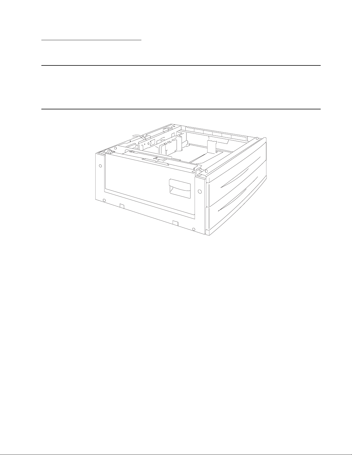
7500-XXX
1. General information
Options and features
This chapter describes features for the 2X 500-Sheet drawer, high capacity feeder, and finisher for the
Lexmark™ X850e, X852e, and X854e MFP.
2X 500-Sheet drawer (2TM)
General information 1-1
Page 18

7500-XXX
2X 500-Sheet drawer (2TM) theory
Driving force transmission path
The rotating force of the 2 tray/tandem tray drive motor is transmitted through the gears to components that
need mechanical driving force as shown below.
MPF/Transport drive motor assembly
Vertical drive gear ASM
Gear18T
Transport
roll ASM
The driving force transmitted to the drive gear 22/40T drives the transport roll assembly through the clutch and
gears.
MPF pick
roll ASM
1-2 Options Service Manual
Page 19
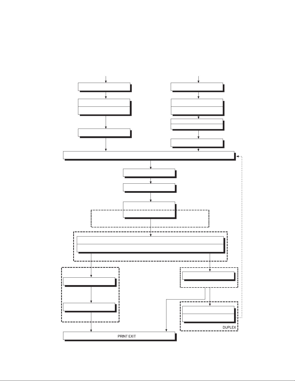
7500-XXX
Media transport
Media transport path
Media is supplied from tray 3 or tray 4, and is transported to the printer along the media transport path shown
below.
Tray 3
Pick roll Pick roll
Separation roll Separation roll
Feed roll
Upper pinch roll
Tray 4
Feed roll
Upper pinch roll
Lower pinch roll
Exit 2 media transport roll ASM
2TM/TTM media Transport roll ASM
Media transport roll ASM
Registration roll ASM
Transfer roll ASM
Drum
Heat roll
Pressure roll
2TM/TTM media Transport
roll ASM
PC cartridge
Fuser unit ASM
Exit 1 media exit roll ASM
Exit 1
Exit 2 media exit roll ASM
Exit 2
Duplex mediatransport roll ASM
Duplex media Center transpor t
roll ASM
General information 1-3
Page 20
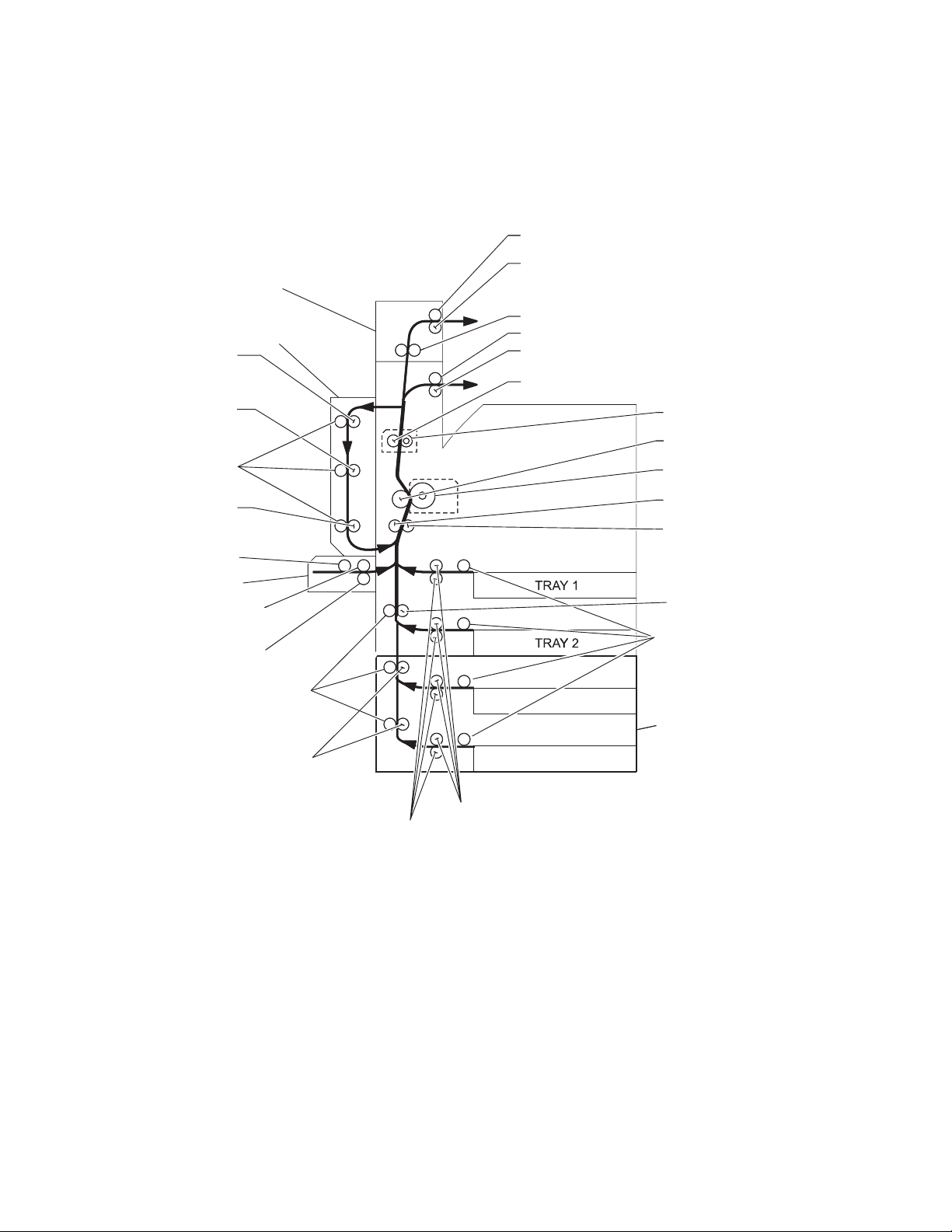
7500-XXX
Layout of media transport path
The following is a cross section of the laser printer and the optional 2 tray module, showing main components
directly associated with the media path and transport.
Main components associated with the media transport
Exit 2 media exit roll assembly
Exit 2 media exit pinch rolls
Option exit 2
Duplex media
transport roll
assembly
Duplex media
center transport
roll assembly
Duplex media
transport pinch roll
Duplex media
transport roll
assembly
MPF pick roll
MPF
MPF Transport
pinch roll
MPF Transport
roll assembly
Media transport
pinch roll
2TM/TTM Media
transport roll
assembly
Option duplex
Exit 2 media transport roll assembly
Exit 1 media exit roll assembly
Exit 1 media exit pinch rolls
Pressure roll
Heat roll
Transfer roll assembly
Drum
Registration pinch
roll
Registration roll
assembly
Transport roll assembly
Pick roll
TRAY 3
Option 2 tray
module (2TM)
TRAY 4
Feed roll
Separation roll
Functions of main components
When the option 2 tray module is installed under the printer, additional trays are available.
The following chapters outline the functions of the main components of the 2 tray module.
1-4 Options Service Manual
Page 21

7500-XXX
Media tray assembly
It is necessary to adjust the front side guide, rear side guide, and end guide on the media tray assembly to
match the media size.
Front media tray guide and rear media tray guide
To adjust the front media tray guide to different media sizes, move it to the front or rear. The front and rear media
tray guides come into contact with the front and rear edges of the media and hold it in position.
The rear side guide moves together with the front side guide.
Media tray end guide
To adjust the media tray end guide assembly to the media length, move the end guide to the left or right.
Bottom plate
The force pushing up the bottom plate is transmitted by the driving force of the media feed lift motor on the
media feed unit assembly to the lift up shaft through the drive gear 13/60T and sector gear 12T. The bottom
plate is pushed up when the lift up shaft is turned, which causes the supplied media to get in contact with the
pick roll assembly.
Media feed unit assembly
Since tray 3 and tray 4 are functionally equivalent in terms of the switch (media size), sensor (media out), sensor
(media level) and sensor (pre-feed), only the components of one tray are described here.
The media feed unit assembly is a mechanical unit for supplying media from the media tray assembly to the
printer. The driving force from the media feed lift motor on the media feed unit assembly is transmitted to the
three roll assemblies to feed media.
When the pick roll picks up media and the remaining media decreases, the actuator of the sensor (media level)
lowers accordingly. When the sensor (media level) detects the lowering, the media feed lift motor is activated to
turn the lift up shaft and the bottom plate is lifted accordingly. The remaining media is ready to be fed out.
Media feed lift motor
This motor is activated to feed media and to lift the bottom plate. When feeding media, it rotates forward to drive
the pick roll. When lifting the bottom plate, it rotates in reverse to drive the tray module gears to turn the lift up
shaft.
Switch (media size)
This switch (media size) changes the setting of the size of media supplied from each media tray assembly. A
signal indicating the set size is transmitted as voltage to the printer engine card assembly.
Sensor (media out)
If media runs out in the media tray assembly, the media out actuator lowers and the flag of the media out
actuator that has stayed in the sensor (media out) sensing area leaves there. Thus, the sensor light is
transmitted. When the sensing area is blocked (media is present), the signal is off.
Sensor (media level)
This sensor detects, by the actuator position, whether media in the media tray assembly is lifted. When the flag
of the actuator leaves the sensor (media level) sensing area, the sensor detects that the media has been lifted.
General information 1-5
Page 22
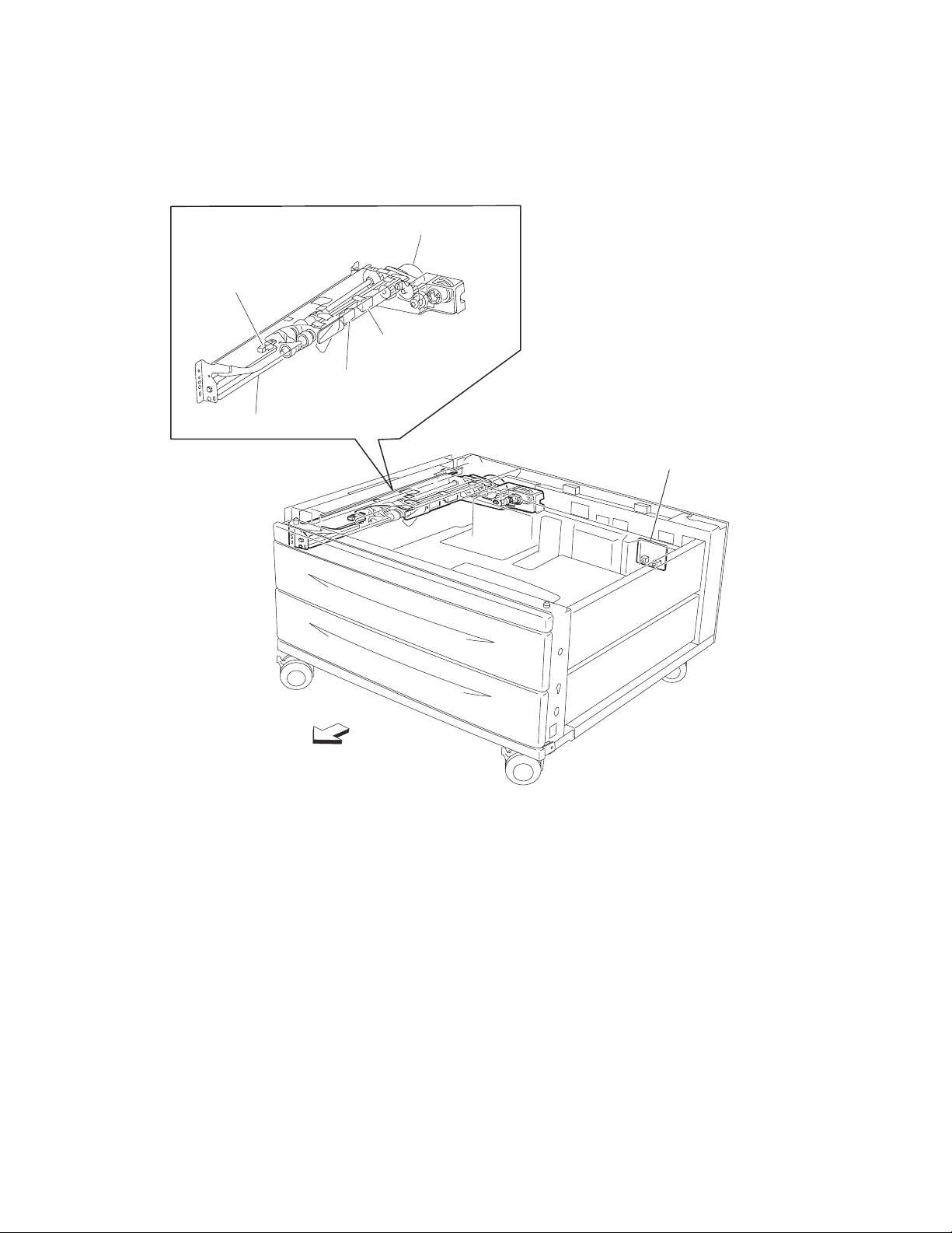
7500-XXX
Sensor (pre-feed)
This sensor detects a media jam in the media tray assembly by the media position and sensor on/off time.
The sensor on/off state is monitored by media passing through the sensor (pre-feed) sensing area.
Media feed lift motor
Sensor (pre-feed)
Sensor (media level)
Sensor (media out)
Media feed unit assembly
Switch (2TM media size)
Front
1-6 Options Service Manual
Page 23
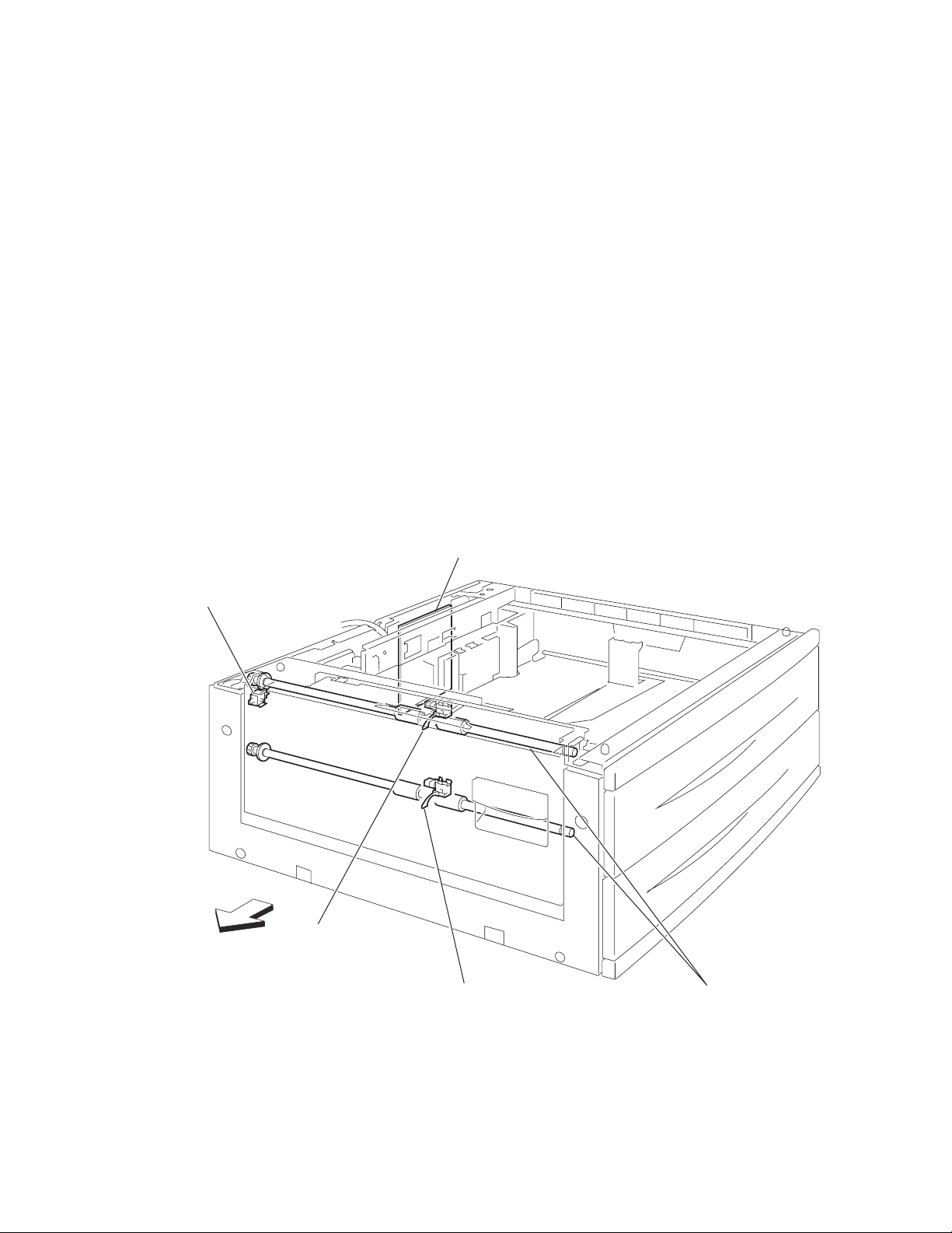
7500-XXX
Main components
Switch (2TM/TTM left door interlock)
The left door interlock switch detects open/close of the left door assembly.
Sensor (tray 3 feed-out)
The sensor (tray 3 feed-out) detects media fed from tray 3 or tray 4.
Sensor (tray 4 feed-out)
The sensor (tray 4 feed-out) detects media fed from tray 4.
2TM/TTM Transport roll assembly
The 2TM/TTM transport roll assembly feeds media from tray 3 or tray 4 to the printer.
2TM/TTM controller card assembly
The 2TM/TTM controller card assembly contains a CPU that controls media feed in the 2 tray module upon
receiving a command from the printer engine card assembly and sensor/switch information.
Switch (2TM/TTM
left door interlock)
LEFT
2TM/TTM
controller card ASM
Sensor
(tray 3 feed-out)
Sensor
(tray 4 feed-out)
2TM/TTM media
transport roll ASM
General information 1-7
Page 24

7500-XXX
Switch (media size)
The following table gives on/off states for the switch (media size), corresponding to the media sizes on the
media tray assembly.
Note: The switches (media size) are denoted by “S/W2”, “S/W4”, “S/W3”, “S/W5”, and “S/W1”, respectively,
from the left side.
Analog switch Digital
Media Size
S/W1 S/W2 S/W3 S/W4 S/W5
No Tray Off Off Off Off Off
5.5” x 8.5” SEF/A5 SEF Off Off On Off Off
B5 SEF Off Off On On On
8.5” x 13” SEF Off On Off On Off
8.5” x 14” SEF Off On Off On On
A4 SEF Off On On Off Off
8.5” x 11” SEF Off On On Off On
A4 LEF On Off On Off Off
A3 SEF On Off On On Off
B5 LEF/Executive LEF On On Off Off On
8K SEF (TFX/GCO) On On Off On Off
B4 SEF On On Off On On
8.5” x 11” LEF On On On Off Off
16K LEF (TFX/GCO) On On On Off On
11” x 17” LEF On OnOnOnOn
switch
1-8 Options Service Manual
Page 25
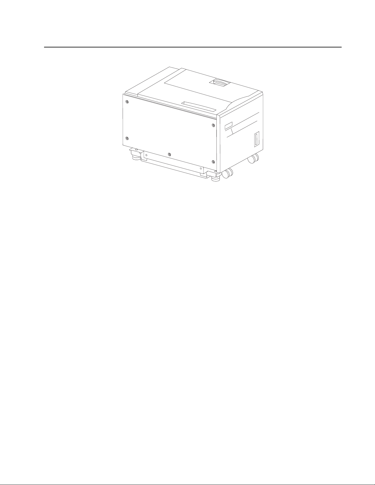
7500-XXX
High capacity feeder
General information 1-9
Page 26

7500-XXX
Media feeding
Outline
The HCF feeds media from the tray to the printer through the HCF media feed unit assembly and the HCF media
transport roll assembly.
HCF media feed unit assembly
The pick roll feeds media from the tray. The feed roll and the separation roll feed media from the pick roll to the
HCF media transport roll assembly.
Rollers are driven by the media feed lift motor on the media feed unit assembly at prescribed timings.
The media fed by the feed roll and separation roll passes through the sensor (pre-feed).
The sensor (pre-feed) detects the presence of media fed from the tray.
The sensor (pre-feed) controls the HCF media feed lift motor speed and on/off operation of the HCF pick
solenoid assembly.
HCF media transport roll assembly
This HCF media transport assembly roll transfers media fed from the HCF media feed unit assembly to the
printer.
The HCF media transport roll assembly is driven by the transport motor installed on the rear side.
The media fed with the HCF media transport roll assembly passes through the sensor (tray 5 feed-out).
1-10 Options Service Manual
Page 27
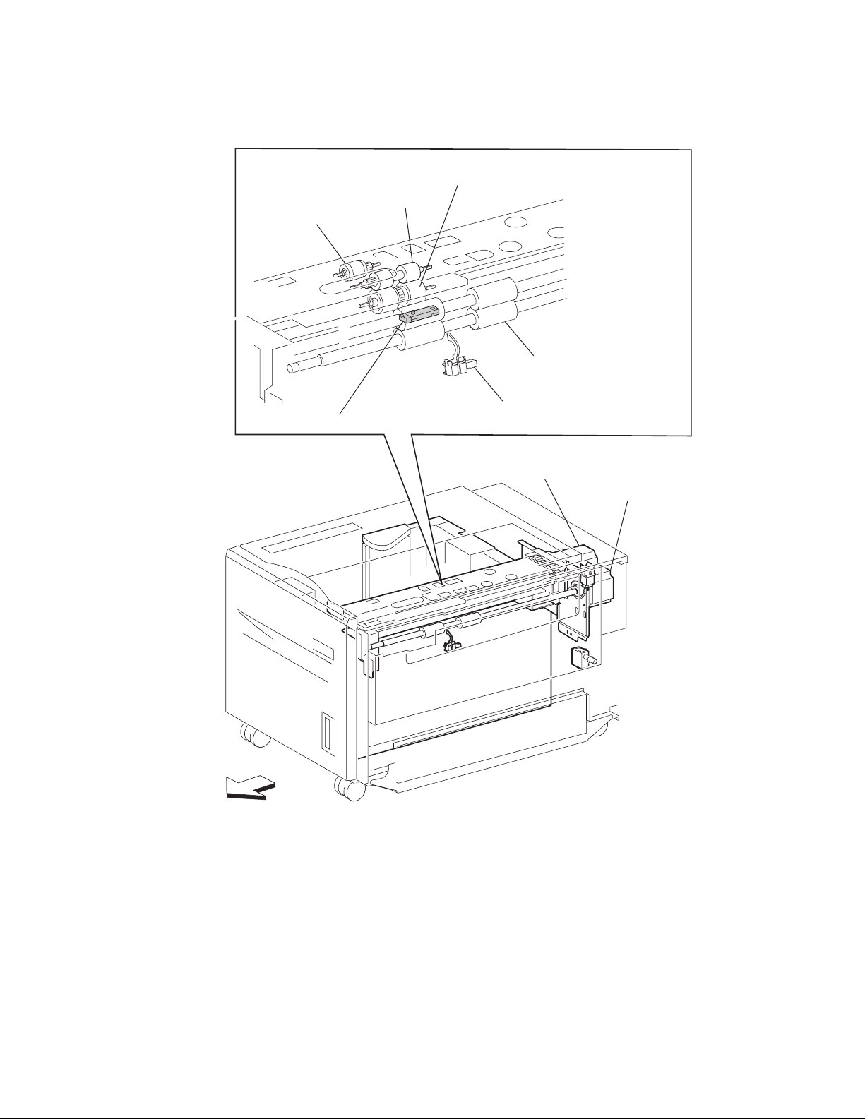
7500-XXX
The sensor (tray 5 feed-out) detects the presence of media fed from the tray and controls the media feed lift
motor stop and the transport motor speed. It also detects media jams to identify the media jam zone.
Separation roll
Pick roll
Sensor (pre-feed)
Feed roll
HCF media
transport roll assembly
Sensor (tray 5 feed-out)
HCF feed lift motor
HCF transport motor
Front
General information 1-11
Page 28
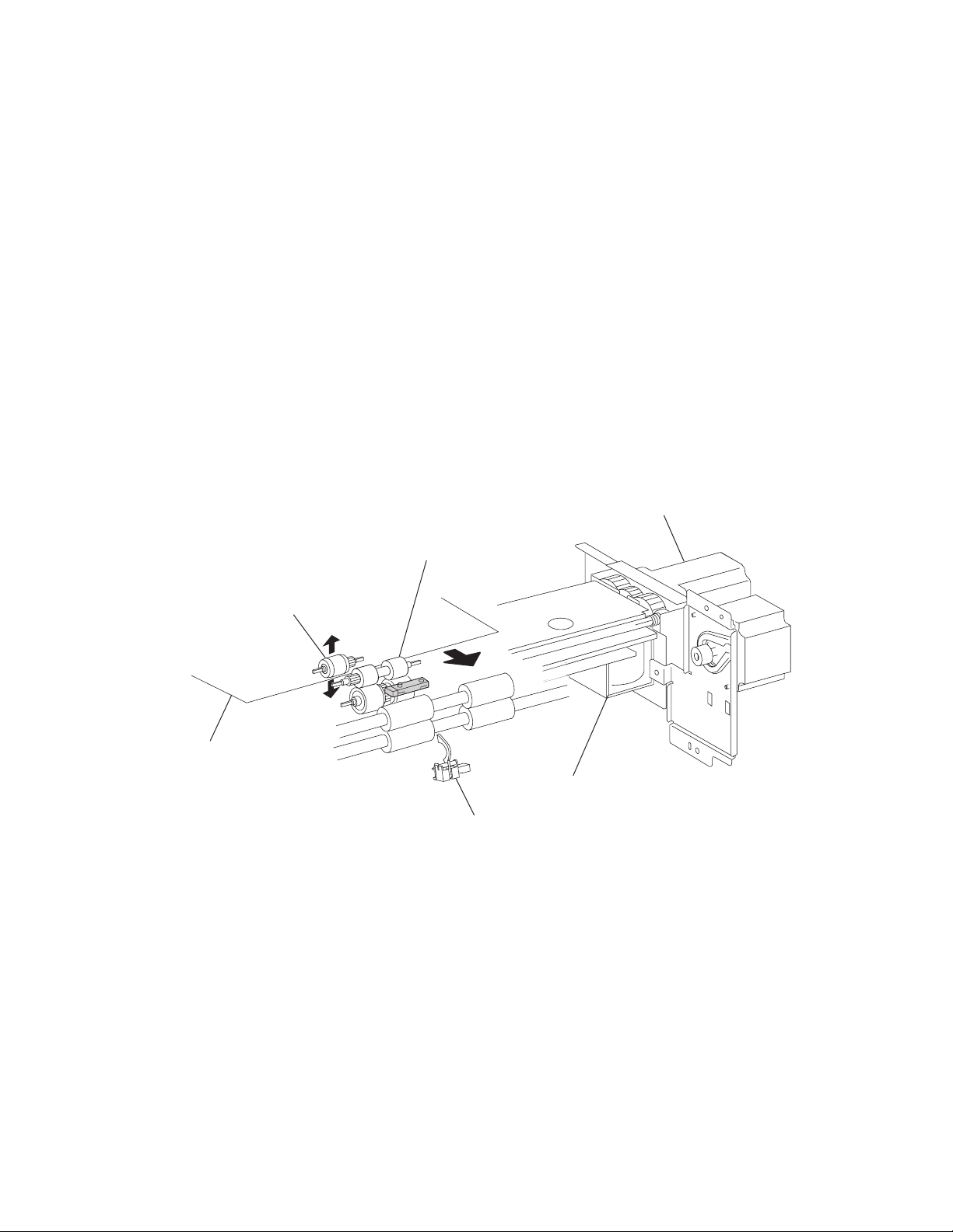
7500-XXX
HCF media feed unit assembly operation
Upon receiving the feed start signal from the controller, the HCF activates the pick solenoid after a preset time
has passed to press the pick roll against the media in the tray.
After a preset time has passed, after receiving the feed start signal, the HCF feed lift motor rotates forward to
feed media from the tray to the feed roll side with the pick roll.
When the end of the media reaches the sensor (pre-feed) and the sensor turns on, the pick solenoid is
deactivated so that the pick roll separates from the media in the tray.
The pick solenoid remains activated at a high voltage for a specified time from its actuation. After that, it is
activated at a low voltage until it is deactivated. If the HCF receives the feed start signal for the next media while
the solenoid is activated at low-voltage, it maintains the actuation state at the low voltage, while pressing the
pick roll against the media in the tray.
When the media is transferred to the printer and the sensor (tray 5 feed-out) turns on, the pick solenoid is
reactivated for a preset time.
Media feed lift motor start/stop timing and revolutions are controlled based on the timing of the HCF feed lift
motor start signal and the sensor (pre-feed).
Thus, media is fed from the tray to the HCF media transport roll assembly.
HCF feed lift motor
Media
Feed roll
Pick roll
HCF pick solenoid
Sensor (tray 5 feed-out)
1-12 Options Service Manual
Page 29
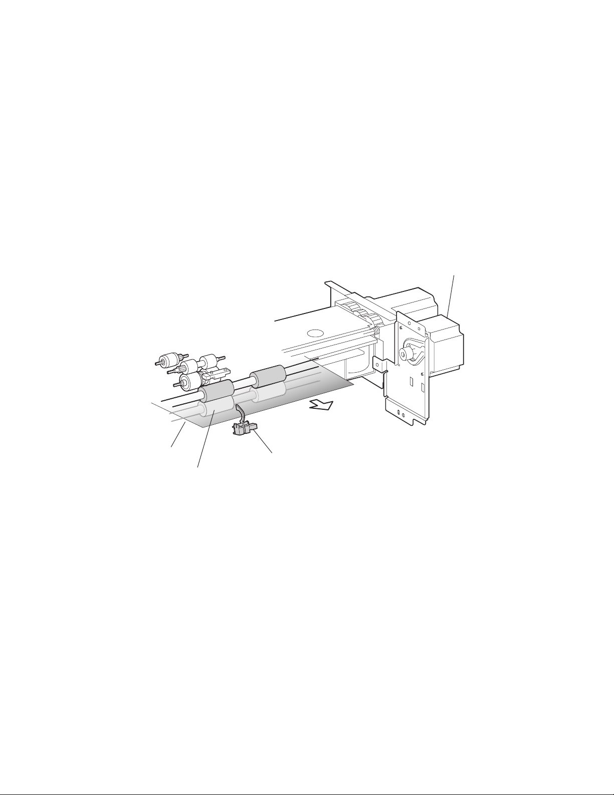
7500-XXX
HCF media transport roll assembly operation
Upon receiving the feed start signal from the controller the HCF activates the HCF transport motor at a high
speed after a preset time has passed. This rotating power of the HCF transport motor is transmitted to the HCF
media transport roll assembly, and the media from the HCF media feed unit assembly is transferred to the
printer.
When the sensor (tray 5 feed-out) is turned on by the media fed with the HCF media transport roll assembly, the
HCF transport motor speed decreases after a preset time has passed.
When the sensor (registration) in the printer is turned on by the media fed from the HCF, the HCF transport
motor turns off.
When the next feed start signal is received, before the HCF transport motor is turned off, the transport motor
continues to rotate.
Thus, media is transferred from the HCF media transport roll assembly to the laser printer.
HCF transport motor
Media
HCF media transport
roll assembly
Sensor (tray 5 feed-out)
General information 1-13
Page 30
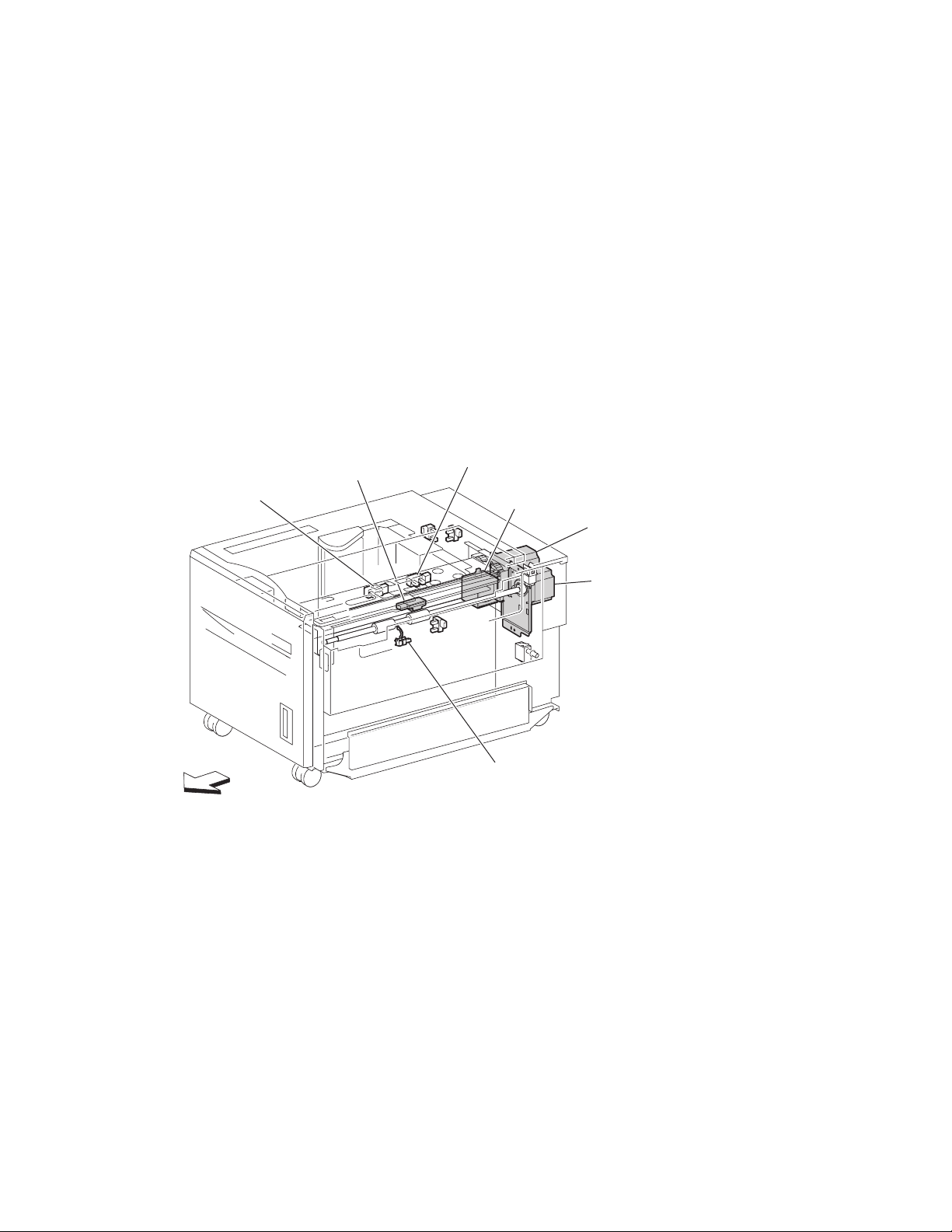
7500-XXX
HCF media feed unit assembly sensor/motor functions
Functions of the sensors and motors of the media feed unit assembly are outlined below.
• HCF media feed lift motor–is a stepping motor that rotates (forward) the pick roll and feed roll to send
media from the tray to the HCF media transport roll assembly. The motor also lifts the tray by reverse
rotation.
• HCF pick solenoid–Raises or lowers the pick roll. The HCF pick solenoid stays activated from the
beginning of media feed until the sensor (pre-feed) turns on. The HCF pick solenoid is activated when the
tray is inserted and when the power is turned on to check the presence of media in the tray.
• Sensor (pre-feed–Detects whether media has been fed from the tray, and controls the HCF feed lift
motor speed. The sensor also becomes a trigger to deactivate the HCF pick solenoid. The sensor turns on
upon detecting media, and determines that media is present.
• HCF transport motor–is a stepping motor that rotates the HCF media transport roll assembly to feed
media to the printer.
• Sensor (tray 5 feed-out)–Detects whether media has been fed from the tray, becomes a trigger to stop
the HCF feed lift motor, and controls the HCF transport motor speed.
The sensor turns on (light receiving) upon detecting media, and determines that media is present.
Sensor
(media out)
Front
Sensor (pre-feed)
Sensor (media level)
HCF pick solenoid
HCF feed lift motor
HCF transport motor
Sensor (tray 5 feed-out)
1-14 Options Service Manual
Page 31

7500-XXX
Status monitoring
This function includes detection of static media jams, interlocking, and insertion of the HCF media tray
assembly.
Static media jam detection
This function checks the status of all relevant sensors on the media path to detect media jams. When media is
present on the sensor, it is treated as a static jam. This detection of media jam is carried out during the start-up
procedure and at every jam/fail detection. The status of all relevant sensors are checked during the start-up
procedure. In addition, the sensor states are checked constantly for the jam/fail detection in order to monitor the
variation in sensor levels.
Interlock detection
This function checks the open state of the switch (top door interlock) and the switch (HCF unit docking interlock).
This detection is constant while the power is on.
When open, the switch (top door interlock) is detected, printing operation is inhibited, and the 24 V supply to the
media feed lift motor and the transport motor is shut off. When open, the switch (HCF unit docking interlock) is
detected, and transfer of media from the HCF is inhibited.
Switch (HCF top door interlock)
Switch (HCF unit docking interlock)
General information 1-15
Page 32

7500-XXX
Tray insertion detection
The sensor (HCF media tray set) checks whether the tray is properly set. This check is constant while the power
is on. Printing operation is inhibited if the sensor (HCF media tray set) off (tray is not present) is detected before
printing starts.
Sensor (HCF media tray set)
HCF media tray
Functions of sensors used for status monitoring
Switch (HCF top door interlock)–Detects open/close of the HCF top door. The on state of this switch
•
indicates the top door is closed.
• Switch (HCF unit docking interlock)–Detects the docking of the HCF with the printer. The off state of
this switch indicates that the HCF is separated from the printer. In this case, transfer of media is inhibited.
• Sensor (HCF media tray set)–Detects insertion of the HCF media tray into the HCF. The sensor turns on
when the HCF media tray is properly inserted. While it is off, media fed from the HCF medial tray is
inhibited.
1-16 Options Service Manual
Page 33

7500-XXX
Media size detection
When media is loaded in the tray, the media size is automatically detected by the rear media edge guide that is
attached to the media tray assembly and aligned with the side of the media. The position of the rear media edge
guide is detected by the sensor (HCF media size L) and the sensor (HCF media size R).
Media size Sensor (HCF media size R) Sensor (HCF media size L)
B5L off off
7.25” x 10.5” L
8.5” x 11” L on off
A4L off on
Note: B5L and 7.25” x 10.5” L can be switched by the NVM.
Sensor (HCF media size R)
Sensor (HCF media size L)
HCF rear media guide
The media size is detected during the start-up procedure and –with the tray inserted–once a specified amount
of time has passed since the sensor (HCF tray set) level was change from off to on. The media size loaded in
the tray is determined when the same media size has been detected a certain number of consecutive times.
If a sensor level pattern does not match the above table, media size cannot be determined. In this case, though
the tray is lifted, starting a print job by feeding media from the tray is inhibited.
Sensor for media size detection
Size sensors
There are two size sensors: sensor (HCF media size R) and sensor (HCF media size L).
Media size can be determined by moving the HCF rear media edge guide to turn on/off these sensors and by
using the sensor level patterns.
General information 1-17
Page 34

7500-XXX
Tray lifting
Tray lift operation starts automatically when the HCF media tray is inserted with media loaded.
Media is lifted and stops at the feeding position. At the same time, detection of no media and remaining media
volume becomes available.
HCF feed lift motor
Feed lift gear bracket asm
Bottom plate
Media out detection
This function checks whether media is loaded in the HCF media tray.
When media is present, the media out actuator in the middle of the HCF is raised as media is lifted, and leaves
the sensing area of the sensor (media out), which makes the sensor light-receivable. The presence of media is
detected.
On the other hand, if media out occurs when the HCF media tray is at the feeding position, the media out
actuator comes inside the sensing area of the sensor (media out), which blocks the light transmission of the
sensor (media out). Media out is detected.
1-18 Options Service Manual
Page 35

7500-XXX
If the HCF media tray is not lifted, the media out actuator remains in the sensing area of the sensor (media out),
while blocking the light transmission of the sensor (media out). Media out is detected regardless of the presence
of media in the tray.
Media out actuator
Sensor (media out)
Detection of media out is carried out constantly after the lifting operation is completed.
When media out is detected, media transfer from the HCF is inhibited.
If media out is detected during printing, print operation of the next media is stopped. However, when the printer
is operating in the Auto Tray Select mode and there is media of the same size in another tray, media is
automatically fed out of the tray.
Sensor (media out)
Detects whether media is present in the HCF media tray.
When this sensor (media out) is off while the tray is at the feeding position, the presence of media is detected.
Remaining media volume detection
This function determines the media volume remaining in the HCF media tray by using the HCF feed lift motor
rotation time and the sensor (media level) during the tray lifting time. The printer notifies operators of remaining
media volume as 25%, 50%, 75%, full, or 0 (zero).
If the remaining media volume becomes zero before no media is detected, the indication remains at (25%).
When the sensor (media level) detects no media, the indication becomes (0) (zero).
When a fault occurs, determination of remaining media volume is carried out as shown below.
• When the interlock is opening during the lifting operation, the remaining media volume is determined
based on the total of the time it takes for the interlock to open, plus the amount of time that transpires from
the media feed lift motor forward/reverse rotation until the sensor comes on.
• When the power is turned off and on during the lifting operation, the remaining media volume is determined
by the lifting time after the power comes on. (The actual volume of media in the tray may differ from the
indication.)
• When the power is turned off and on while the tray is at the feeding position, the sensor (media level) is on
when the power is turned on, and the remaining media volume before the previous power off is regarded
as the remaining media volume.
General information 1-19
Page 36

7500-XXX
• If the sensor (media level) is off when the power is turned on, the HCF regards the HCF media tray as
having been removed, and determines the remaining media volume based on the time from the media feed
lift motor forward/reverse rotation until the sensor (media level) comes on.
Sensor (media level)
Detects the media feeding position in the tray in order to control the media position.
While this sensor (media level) is off, lifting the tray is continued until the sensor (media level) turns on.
Front
Sensor (media level)
HCF pick solenoid
HCF feed lift motor
1-20 Options Service Manual
Page 37

7500-XXX
Finisher
The optional finisher performs staples and punches, and stacks media transferred from the Lexmark X850e,
X852e, or X854e MFP. Output is stacked in the upper media bin or separately collated in the stacker media bin.
Bridge unit assembly
Finisher weight
Packaged: 42 kg
Unpacked: 30 kg
Components
The finisher is composed of the following components.
• Bridge unit assembly block to feed media from the printer to the finisher
• Punch block to punch media
• Compiler tray block to align media
• Stapler block to staple a set of media at specified positions
Finisher
General information 1-21
Page 38

7500-XXX
Stacker media bin block to stack media
Bridge unit assembly
Media size and weight
The following shows media sizes and weights that the finisher can handle, as well as applicable functions for
each media size.
The printer and the finisher handle different media sizes and weights. For this reason, if the printer has printed
media that the finisher cannot handle, the exit 1 diverter gate in the printer is switched to eject the media from
Exit 2 onto the bridge unit assembly. Refer to the Printer Service Manual for additional information on the printer.
Punch unit
Stacker media bin
Compiler tray
Stapler
1-22 Options Service Manual
Page 39

7500-XXX
Media size/orientation and applicable functions
Top
tray
Stacker
Stack Stack
Offset
stack
Punch Staple
Media
description
Size
B5
182 x 257 mm
Executive 7.25 x 10.5 in.
184.2 x 27 0 mm
Letter 8.5 x 11 in.
215.9 x 279.4 mm
A4
210 x 297
Short edge
first (SEF)/
Long edge
first (LEF)
SEF Yes No No No No
LEF Yes Yes Yes Yes
SEF Yes No No No No
LEF Yes Yes Yes Yes
SE F Ye s Ye s Yes Yes
LEF Yes Yes Yes Yes
SE F Ye s Ye s Yes Yes
LEF Yes Yes Yes Yes2
Folio (foolscap) 8,5 x 13 in. SEF Yes Yes Yes Yes
Legal 8.5 x 14 in. SEF Yes Yes Yes Yes
B4
SE F Ye s Ye s Yes Yes
257 x 364 mm
A3
SE F Ye s Ye s Yes Yes
297 x 420 mm
Ledger 11 x 17 in. SEF Yes Yes Yes Yes
a(2)
a(2,3,4)
a(2)
a(2,3,4)
a(2)
,a(3,4)
a(2)
a(2)
a(2)
a(2,3,4)
a(2,3,4)
Yes
No
Yes
Yes
Yes
Yes
Yes
Yes
Yes
Yes
Yes
Custom size Same width with
Yes Ye s Yes Ye s Yes
standard size
b
Custom size Besides above Yes Yes
a
Numbers (2,3,4) mean 2 holes, 3 holes, and 4 holes, respectively.
b
Applicable within the following range:
Yesb No No
Media width: 203.2—297 mm
Media length: 182—431.8 mm
Media weight
Description Maximum weight
For punching 52–176 gsm
For stapling 52–226 gsm*
For ejecting in the stacker media bin 52–226 gsm
For ejecting in the upper media bin 52–226 gsm
* The amount of media capable of being stapled will be less than 50 if the media
weight is greater than 90 g/m
2
.
General information 1-23
Page 40

7500-XXX
Features
Media processing requested Destination of media
No post-processing Upper media bin or stacker media bin
Punching Upper media bin or stacker media bin
Stapling Stacker media bin
Punching and stapling Stacker media bin
Finisher theory
Media transport
This section describes the transfer of media from the printer to a specified bin.
The following figures illustrate layouts (front view) of sensors, rollers, and main blocks, as well as a layout (rear
view) of the main components.
Bridge unit assembly paper path
From printer
Sensor (bridge unit media entrance)
Finisher media path
Punch unit
From
bridge unit
Stapler unit
Transport
belt
To finisher
Sensor (bridge unit
media exit)
Upper media bin
Stacker media bin
Compiler media
unit assembly
1-24 Options Service Manual
Page 41

7500-XXX
Finisher roll assemblies
Upper media exit roll assembly—
Upper media transport
roll assembly—driven
by drive motor (buffer/transport)
driven by drive motor (exit)
Finisher diverter gate
Sub paddle—
driven by drive motor (entrance/paddle)
Finisher media entrance
roll assembly—driven by
drive motor
(entrance/paddle)
Buffer roll assembly—
driven by drive
motor buffer/transport
Buffer diverter gate
Finisher media path sensors
Sensor (diverter gate)
Sensor (finisher
media entrance)
Main paddle—
driven by drive motor
(entrance/paddle)
Sensor (upper media exit)
Eject clamp—
driven by media eject clamp motor
Media eject shaft assembly—
driven by media eject motor assembly
Lower media exit roll assembly—
driven by drive motor (exit)
Sensor (upper media bin full)
Sensor (lower
media exit)
From
bridge unit
Sensor (buffer path)
Sensor (compiler media in)
General information 1-25
Page 42

7500-XXX
Finisher motors
Drive motor (exit)
Media eject clamp motor
Media eject motor assembly
Stacker bin lift
motor assembly
Bridge unit assembly
When the printer designates the finisher, the media diverter gate in the printer activates and media is fed from the
printer into the bridge unit assembly.
Drive motor
(buffer/transport)
Finisher diverter gate solenoid
Buffer diverter solenoid
Drive motor
(entrance paddle)
The bridge unit drive motor is activated by the trigger of the printer’s registration clutch, which drives the transport
belts in the bridge unit assembly. The motor power is transmitted to the two belts between the bridge unit right shaft
assembly and the bridge unit left shaft assembly.
The media fed to the bridge unit assembly is securely held between the transport belts and the pinch rolls, and fed to
the finisher.
Bridge unit drive motor
Bridge unit right
shaft assembly
Bridge unit
pinch roll
Bridge unit left
Transport belt
shaft assembly
1-26 Options Service Manual
Page 43

7500-XXX
From bridge unit assembly to punch
The media fed from the bridge unit assembly is fed into the finisher by the media entrance roll assembly located
on the entrance section of the finisher which is driven by the drive motor (entrance/paddle).
The media route inside the finisher is determined by the finisher diverter gate.
The finisher diverter gate is activated by the finisher diverter gate solenoid controlled by the printer.
The media is further fed in the finisher by the two upper media transport roll assemblies, or the buffer roll
assemblies that are driven by the motor (buffer/transport), and passes through the punch unit.
The sensor (finisher media entrance) becomes low upon detecting media. After a certain amount of time has
passed and the level has transitioned to high, the motor (buffer/transport) that drives the upper media transport
roll assembly or the buffer roll assembly starts reverse rotation.
The media is returned to the punch unit by the upper media transport roll assembly or the buffer roll assembly,
and is stopped with its end gently pressed against the three punch media stopper assemblies.
The three punch media stopper assemblies in the punch unit drop to let media pass through when media is fed
to the exit (while the motor (buffer/transport) is rotating forward), but rise when media is returned (while the
motor (buffer/transport) is rotating reversely) to stop the media.
Thus, punch hole positions in the media feed direction are determined.
Drive motor (buffer/transport)
Punch unit
Finisher diverter
gate solenoid
Drive motor
(entrance paddle)
Sensor (finisher
media entrance)
Upper media transport roll assembly—driven by
drive motor (buffer/transport)
Punch unit
Sensor (finisher
media entrance)
Media
From bridge unit assembly
Finisher media entrance
roll assembly—driven by
drive motor (entrance/paddle)
Upper media transport
roll assembly
Punch unit
Finisher diverter gate
Buffer roll assembly
Finisher media
entrance roll
assembly
Finisher diverter gate
Buffer roll assembly—
driven by drive motor (buffer/transport)
General information 1-27
Page 44

7500-XXX
From punch to compiler unit assembly
The media is transferred to the compiler unit assembly by the buffer roll assembly (driven by the motor (buffer/
transport)) and by the lower media exit roll assembly (driven by the drive motor (exit)).
When the first media reaches the compiler unit assembly, the media eject clamp motor is activated to lower the
media eject clamp so that the media eject clamp and the media eject shaft assembly can clamp the media.
Thus, the media transferred from the punch unit is held by the media eject shaft assembly and the media eject
clamp (driven by the media eject motor assembly) and is fed to the exit.
When the media trailing edge passes through the sensor (lower media exit), the media eject motor assembly
starts reverse rotation to return the media to the compiler unit assembly.
When the following media reaches the compiler unit assembly, the media eject clamp is raised, and the media
that has passed through the lower media exit roll assembly falls on the compiler unit assembly.
At this time, the three main paddles are rotated by the main paddle shaft assembly to feed the media so that the
media trailing edge butts against the rear wall of the compiler unit assembly.
The sub paddle solenoid of the media eject unit assembly is activated to lower the sub paddle so that the media
can be fed to the compiler unit assembly.
Media eject clamp motor
Drive motor (exit)
Drive motor
(buffer/transport)
Buffer diverter solenoid
Drive motor (entrance/paddle)
Media eject motor assembly
Sensor (lower media exit)
Eject clamp
Buffer roll assembly
Buffer diverter gate
Media eject
shaft assembly
Lower media exit
roll assembly
Compiler unit assembly
1-28 Options Service Manual
Page 45

7500-XXX
Sensor (lower media exit)
Sub paddle—driven by
drive motor (entrance/paddle)
Buffer roll assembly—
driven by drive motor
(buffer/transport)
Media eject shaft assembly—
Eject clamp—driven
by eject clamp motor
driven by media eject motor asm
Buffer diverter
Main paddle
motor—driven by
motor (entrance/paddle)
When printing multiple sets, while stapling the first set on the compiler unit assembly or ejecting it to the stacker
media bin, the first media of the second set will not be fed to the compiler unit assembly.
When the first media of the second set reaches the finisher, the buffer diverter solenoid is activated by the printer
command and by the sensor (finisher media entrance) to switch the buffer diverter gate.
Thus, the media route is switched into the buffer roll assembly’s circumferential direction. (This operation is
called the buffer path.)
The first media of the second set is aligned with the second media, and then they are fed together to the
compiler unit assembly.
Even for one sheet of media, the buffer path operation is executed in the same way. The media is stacked
temporarily on the compiler unit assembly, and then ejected in the stacker media bin.
After the buffer path is executed for the first media, if a second media of a different size comes, the first media is
fed to the compiler unit assembly, but the second one is fed to the compiler unit assembly without the buffer
path. At this time, a certain delay time is provided to prevent the second media from colliding with the first one.
Compiler unit assembly
Lower media exit
roll assembly—driven by
motor (exit)
Media
Sensor
(buffer path)
Buffer roll assembly
driven by drive motor
(buffer/transport)
Buffer
diverter gate
Compiler unit
assembly
General information 1-29
Page 46

7500-XXX
From compiler unit assembly to stacker media bin
Stapled media on the compiler unit assembly (stapling mode) or aligned media (non-stapling mode) are held
between the media eject clamp and the media eject shaft assembly.
The media eject shaft assembly is driven by the media eject motor assembly to transfer media to the stacker
media bin.
After media is transferred to the stacker media bin, it is held by the clamp paddle attached to the media eject
shaft assembly.
From punch to upper media bin
The media to be ejected to the upper media bin is switched in the media path by the finisher diverter gate
located behind the punch and fed in the upper media transport roll assembly direction.
The finisher diverter gate is switched by the finisher diverter gate solenoid. While the solenoid is activated,
media is fed in the upper media transport roll assembly direction.
The two upper media transport roll assemblies driven by the motor (buffer/transport) feed media to the upper
media exit roll assembly top at the top of the finisher.
The upper media exit roll assembly top driven by the drive motor (exit) ejects the media to the upper media bin.
The upper media exit roll assembly decelerates after a specified period of time from the following trigger events.
Functions of sensors along the media path
Bridge unit assembly
•
Sensor (bridge unit media entrance)
— A photo-interrupter sensor that detects whether media is fed from the printer to the bridge unit
assembly
— It turns high (+5 V dc) (light receiving) when media enters the bridge unit assembly.
• Sensor (bridge unit media exit)
— A photo-interrupter sensor that detects whether media passes through the bridge unit assembly
— It turns high (+5 V dc) (light receiving) when media reaches this sensor, and turns low (0 V dc) when
media exits from the bridge unit assembly.
• Sensor (bridge unit top cover interlock)
— A photo-interrupter sensor that detects open/close of the bridge top cover assembly of the bridge unit
assembly
— It turns high (+5 V dc) (light receiving) when the bridge top cover assembly opens.
Sensor (bridge unit media exit)
Sensor (bridge unit media entrance)
1-30 Options Service Manual
Sensor (bridge unit top
cover interlock)
Page 47

7500-XXX
Finisher
Sensor (finisher media entrance)
•
— A photo-reflective sensor detects whether media is fed from the bridge unit assembly to the finisher
— It turns high (+5 V dc) while media is present within the sensing area.
— When the level turns high due to the first media of the second set during multi-set printing, this sensor
activates the buffer diverter solenoid to switch the buffer diverter gate so that the media goes in the
buffer roll assembly’s circumferential direction.
• Sensor (diverter gate)
— A photo-reflective sensor that detects the leading edge of the media
— It turns low (0 V) when the front end reaches the sensing area.
• Sensor (lower media exit)
— A photo-interrupter sensor that detects whether media passes through the sensor (lower media exit)
— It turns high (+5 V) (light receiving) when the actuator is driven out of the sensing area by the media.
— When the level turns high, this sensor activates the front tamper motor and the rear tamper motor on
the compiler unit assembly.
— This sensor is also used to control on/off of the media eject motor assembly
• Sensor (compiler media present)
— A photo-interrupter sensor that detects whether media is present or not on the compiler unit
assembly.
— While media is present, the actuator is outside the sensing area, and the sensor turns high (+5 V dc)
(light receiving).
• Sensor (buffer path)
— A photo-interrupter sensor that detects whether media is fed toward the buffer roll assembly
— While media is present, the actuator is outside the sensing area, and the sensor turns at high
(+5 V dc) (light receiving).
• Sensor (upper media exit)
— A photo-interrupter sensor that detects whether media is fed to the upper media exit roll assembly top
at the exit side of the upper media bin
— When the media is fed, the actuator leaves from the sensing area, and the sensor turns high
(+5 V dc).
• Sensor (upper media bin full)
A photo-reflective sensor that detects the stack volume of media in the upper media bin
Sensor (diverter gate)
Sensor (finisher
media entrance)
From bridge unit
Sensor (buffer path)
Sensor (upper media exit)
Sensor (upper media bin full)
Sensor (lower media exit)
Sensor (compiler media in)
General information 1-31
Page 48

7500-XXX
Punch unit
This section describes the media punching operation of the punch.
Two types of punch are provided: the 2/3-hole type and the 2/4-hole type.
The following explains the 2/3-hole type (2-hole/3-hole auto-switching).
Every type has the same construction, except for the sensor (punch hole select) that is provided for the 2-hole
type and 3-hole type only.
Adjusting punching positions
The punching positions from the media edge in the direction of feed are determined by gently pressing the
media against the three punch media stopper assemblies.
The three punching positions from the media edge in the direction of media width are determined by the
following method.
• Activate the punch carriage shift motor assembly and move the punch to the front side until the sensor
(punch carriage shift HP) turns low.
• Reversely rotate the motor and move the punch to the rear side until the sensor turns high to determine the
home position.
• The punch carriage shift motor assembly is activated to move the punch to the front until the sensor (punch
unit side registration 1) and the sensor (punch unit side registration 2) detects the media edge, and then
the punch is further moved to the front according to the pulse-number determined by the media size. (The
punch carriage shift motor assembly stops at this position.)
Sensor (punch carriage shift HP)
Sensor (punch cam front)
Sensor (punch
hole select)
Sensor (punch unit HP)
Sensor (punch unit motor encoder)
Punch carriage shift motor assembly
Sensor (punch unit side
registration 2)
Sensor (punch unit side
registration 1)
Punch unit motor
1-32 Options Service Manual
Page 49

7500-XXX
Punching
After punching positions are determined, the punch unit motor is activated to move the cam plate. With the
movement of the cam plate, the pins descend along the guide holes to punch the media.
This operation is performed for each sheet of media.
The cam plate can lower the pins even while it is moving to the front or rear side.
The punch unit motor is rotated forward or reversely for each sheet of media, which is triggered by the sensor
(punch cam front) being turned on/off.
Pin position
Sensor (punch hole select)
Home
position
Sensor (punch cam front)
Sensor (punch unit HP)
Punch unit motor
Pin
Cam plate
3 hole
position
Home
position
2 hole
position
Home
position
General information 1-33
Page 50

7500-XXX
Detecting punch waste full
Punch waste is stored in the punch waste box.
A sensor is provided to detect punch waste full.
When punch waste full is detected, it is notified to the operator only once.
Even if punch waste is not removed, the finisher can still punch media. However it can spread punch waste
inside the machine.
Detecting punch waste box
The sensor (punch waste box set) detects whether the punch waste box is properly set.
When the sensor (punch waste box set) does not detect that the punch waste box is properly set for four
seconds, the punch waste box count is reset.
Functions of punch sensors/motors
Sensor (punch unit side registration 1)
•
— A photo-reflective sensor that detects the side edge of large media
— Media side edge is detected by On/Off of this sensor while shifting the punch (containing this sensor)
in the direction of media width.
— The sensor remains at high (+5 V dc) while media is present, and turns low when media side edge is
detected.
• Sensor (punch unit side registration 2)
— A photo-reflective sensor that detects the side edge of small media
— This sensor has the same function as the sensor (punch unit side registration 1).
• Sensor (punch carriage shift HP)
— A photo-interrupter sensor that detects the home position of the moving punch
— It turns high (+5 V dc) (light blocking) when the home position is detected.
• Sensor (punch unit HP)
— A photo-interrupter sensor that detects the home position of the cam plate that lowers the punching
pins
— It turns high (+5 V dc) when the home position is detected.
• Sensor (punch hole select)
— A photo-interrupter sensor that detects the rear position of the cam plate
— It turns high (+5 V dc) when the rear position is detected.
— This sensor also detects the cam position to switch punch holes (2-hole/3-hole).
• Sensor (punch cam front)
— A photo-interrupter sensor that detects the front position of the cam plate
— It turns high (+5 V dc) when the front position is detected.
— This sensor is used to determine to which side (front or rear) the cam plate should be moved.
• Sensor (punch unit motor encoder)
— A photo-interrupter sensor that detects pulse generated by the encoder attached to the punch unit
motor
— It counts punch unit motor revolutions, and becomes a trigger to stop the motor (by shutting off the
current).
• Punch carriage shift motor assembly
A stepping motor to move the punch in the media width direction
• Punch unit motor
— A DC motor to move the cam plate that lowers the punching pins
— Forward rotation of the motor moves the cam plate to the front side, and reverse rotation moves it to
the rear side.
1-34 Options Service Manual
Page 51

7500-XXX
• Sensor (punch waste box set)
— A photo-interrupter sensor that detects whether the waste box is properly set
— When the punch waste box is properly set, the actuator of the box blocks the light transmission of the
sensor, which turns the sensor to high (+5 V dc).
• Sensor (punch waste box full)
A photo-interrupter sensor that detects whether the punch waste box is filled with punch waste.
Sensor (punch carriage shift HP)
Sensor (punch cam front)
Sensor (punch
hole select)
Sensor (punch unit HP)
Sensor (punch unit
motor encoder)
Compiler unit assembly
This section describes the operation of the compiler unit assembly which aligns the media edge transferred from
the punch unit.
Outline of operation
When media is fed onto the compiler unit assembly, tamping is performed to align the media edge in the media
width direction.
Punch carriage shift motor
Sensor (punch unit side registration 2)
Sensor (punch unit side
registration 1)
Punch unit motor
When ejecting stapled sets of media to the stacker media bin, if they are stacked in the stacker media bin with
the same staple position, the height of the stapled portion will increase. This will cause improper compiling of
media due to butting of the following media. To prevent such improper compiling, offsetting is required by shifting
the staple position between sets of media.
Rear tamper
Front tamper
Sensor (rear
tamper HP)
Rear tamper motor
Sensor (compiler
media in)
Front tamper motor
Sensor (front tamper HP)
General information 1-35
Page 52

7500-XXX
Capacity of compiler unit assembly
Media volume that can be stacked on the compiler unit assembly is limited as shown in the table below.
The number of sheets depends on whether media is stapled or not, as well as on media size.
If the number of sheets of one set to be stapled exceeds the limit, the exceeding sheets are not stacked on the
compiler unit assembly, and are forcibly ejected to the stacker media bin without being stapled.
This forcible ejection is performed to prevent damage to the staple assembly.
When feeding large media in the non-staple mode, there may be a misalignment depending on media
characteristics. For this reason, the default media capacity is set to a smaller value.
Compiler unit assembly media capacity
Condition Min. Default Max.
Staple mode 2 50 75
For small media (less than 216 mm in the feed direction) in
non-staple mode
For large media (216 mm or more in the feed direction) in
non-staple mode
10 50 100
10 25 100
Compiler unit assembly operation with multiple media sizes
When two or more media sizes are used and their widths are the same (example: A4L and A3S), all the sheets
are compiled and stapled as a set on the compiler unit assembly, and then ejected to the stacker media bin.
When two or more media sizes with different media width are used, stapling media on the compiler unit
assembly is stopped when a different size is detected. Such different-size sheets of media are forcibly ejected to
the stacker media bin.
Tamping
When media is fed from the punch to the compiler unit assembly, tamping is performed to align the media in the
media width direction on the compiler unit assembly.
Tamping is an operation to align media to the specified position on the compiler unit assembly. The front tamper
or rear tamper is moved to the end of the media by its motor.
Tamping is executed each time when a sheet of media reaches the compiler unit assembly. Additional tamping is
executed after the last sheet is tamped.
There are three types of tamping.
• Front tamping–Tamping by the rear tamper with the front tamper fixed at the home position
• Rear tamping–Tamping by the front tamper with the rear tamper fixed at the home position
• Center tamping–Tamping by the front and rear tampers to align media to the center
1-36 Options Service Manual
Page 53

7500-XXX
Front tamping
Front tamping is used in the following cases.
• In the non-staple mode
• When executing front stapling (corner)
The tamper positions during front tamping are shown below.
Sensor (front tamper HP)
Front
Sensor (rear tamper HP)
Rear
Front tamper motor
Position Description
1 Front tamper home position–sensor (front tamper HP)
2 Front tamper size position
3 Front tamper offset position
4 Rear tamper home position–sensor (rear tamper HP)
5 Rear tamper standby position
6 Rear tamper tamping position
7 Rear tamper offset position
Front tamper
Rear tamper
Rear tamper motor
General information 1-37
Page 54

7500-XXX
Rear tamping
Rear tamping is used in the following cases.
• When executing rear stapling (corner)
• When executing dual stapling
The tamper positions during rear tamping are shown below.
Sensor (front tamper HP)
Front
Sensor (rear tamper HP)
Rear
Front tamper motor Front tamper
Position Description
1 Front tamper home position–sensor (front tamper HP)
2 Front tamper tamping position
3 Front tamper offset position
4 Rear tamper home position–sensor (rear tamper HP)
5 Rear tamper size position
6 Rear tamper offset position
Rear tamper
Rear tamper motor
1-38 Options Service Manual
Page 55

7500-XXX
Center tamping
Center tamping is used when executing rear stapling (straight).
The tamper positions during center tamping are shown below.
Sensor (front tamper HP)
Front
Sensor (rear tamper HP)
Rear
Front tamper motor Front tamper
Position Description
1 Front tamper home position–sensor (front tamper HP)
2 Front tamper standby position
3 Front tamper tamping position
4 Front tamper offset position
5 Rear tamper home position–sensor (rear tamper HP)
6 Rear tamper standby position
7 Rear tamper size position
8 Rear tamper offset position
Rear tamper
Rear tamper motor
Determining tamper home position
When the sensor (lower media exit) turns high (+5 V dc) (light receiving), the front and rear tamper motors on
the compiler unit assembly are activated, and the front and rear tampers start moving.
The front tamper home position is determined when the front tamper enters the sensor (front tamper HP)
sensing area.
In the same way, the rear tamper home position is determined when the rear tamper enters the sensor (rear
tamper HP) sensing area.
Tamping
Tamping is executed after a preset time has passed after the sensor (compiler media present) turns high
(+5 V dc) when media is detected on the compiler unit assembly.
General information 1-39
Page 56

7500-XXX
Offsetting
Offsetting is an operation to shift the position of media to be ejected to the stacker media bin so that boundaries
between media units (sets of media, job units, etc.) can be easily recognized.
Offsetting is executed for staple positions:
• During front stapling (corner)–Shifts stapled sheets using the front tamper by 20 mm to the rear side
before ejecting them to the stacker media bin
• During rear stapling (corner/straight)
— For media with a width of 216 mm or more [rear staple (corner)]–Shifts stapled sheets using the rear
tamper by 20 mm to the front side before ejecting them to the stacker media bin
— For media with a width of less than 216 mm [rear staple (straight)]–Shifts stapled sheets using the
front tamper by 9 mm to the rear side before ejecting them to the stacker media bin.
During dual stapling:
• Shifts stapled sheets using the front tamper by 9 mm to the rear side before ejecting them to the stacker
media bin.
• Offsetting is not executed (0 mm) for small media.
Functions of compiler unit assembly sensors/motors
Sensor (compiler media in)
•
— A photo-interrupter sensor that detects whether media is present or not on the compiler unit assembly
— When media is detected, the actuator leaves the sensing area, which turns the sensor to high
(+5 V dc) (light receiving).
• Sensor (front tamper HP)
— A photo-interrupter sensor that detects the front tamper home position
— When the front tamper comes to the home position, it enters the sensor’s sensing area, which turns
the sensor to high (+5 V dc) (light blocking).
• Sensor (rear tamper HP)
— A photo-interrupter sensor that detects the rear tamper home position
— When the rear tamper comes to the home position, it enters the sensor’s sensing area, which turns
the sensor to high (+5 V dc) (light blocking).
• Front tamper motor
— A stepping motor that moves the front tamper for tamping
— Clockwise rotation of this motor moves the front tamper to the rear side. Counterclockwise rotation of
this motor moves the tamper to the front side.
1-40 Options Service Manual
Page 57

7500-XXX
• Rear tamper motor
— A stepping motor that moves the rear tamper for tamping
— Clockwise rotation of this motor moves the rear tamper to the front side. Counterclockwise rotation of
this motor moves the tamper to the rear side.
Rear tamper
Front tamper
Sensor (rear
tamper HP)
Rear tamper motor
Sensor (compiler
media in)
Front tamper motor
Sensor (front tamper HP)
Stapler
This section describes the operation of the stapler.
Stapling operation
Sheets of media fed from the punch are tamped on the compiler unit assembly, and then stapled at specified
positions by the command of the printer.
Staple positions
There are four stapling modes:
• Front staple (corner) [front corner]
The stapler staples a set of media obliquely (45 degrees) after the rear tamper
aligns the media to the front side.
Rear
Process direction
Front
• Rear staple (corner) [rear corner]
This type of stapling is applied for media with a width of 216 mm or more.
The stapler moves to the rear corner and staples a set of media obliquely (45
degrees) after the front tamper aligns the media to the rear side.
Rear
Process direction
Front
General information 1-41
Page 58

7500-XXX
• Rear Staple (Straight) [rear straight]
This type of stapling is applied for media with a width of less than 216 mm.
The Stapler staples a set of media in parallel with the media edge after the front
tamper aligns the media to the rear side.
Rear
Process direction
Front
• Dual Staple [dual]
The Stapler staples a set of media at fixed positions (front/rear sides) in parallel
with the media edge after the front tamper aligns the media to the specified position
for each media size.
Rear
Process direction
Front
Media sizes that allow stapling
Media size that allows stapling depends on stapling positions.
The following table shows media sizes and the applicability of stapling for each staple position.
Front
corner
A3 SEF Yes Yes No Yes
A4 LEF Yes Yes No Yes
11 x 17 in. SEF Yes Yes No Yes
8.5 x 11 in. LEF Yes Yes No Yes
8K SEF(GCO), 16K LEF(GCO) Yes Yes No Yes
B4 SEF, B5 LEF Yes Yes No Yes
8 x 10 in. LEF Yes Yes No Yes
8.5 x 14 in. SEF / 8.5 x 13 in. SEF /
8.5 x 11 in. SEF
A4 SEF Yes No Yes Yes
8 x 10 in. SEF Yes No Yes Yes
Yes: Applicable, No: Not applicable
Yes No Ye s Ye s
Rear
corner
Rear
straight
Dual
Stapling one sheet
Upon receiving the stapling command from the printer with one sheet remaining on the compiler unit assembly,
the finisher ejects the media to the stacker media bin without stapling it.
1-42 Options Service Manual
Page 59

7500-XXX
Stapling multiple size media
When sheets with different sizes and the same width (example: A4L and A3S) are present on the compiler unit
assembly, all the sheets are stapled and then ejected to the stacker media bin.
When sheets with different widths are present on the compiler unit assembly, stapling is stopped when a
different width is detected. Such different-width sheets are forcibly ejected to the stacker media bin.
Media limits for stapling
The number of sheets to be stapled is limited to prevent damage to the stapler.
• If the number of sheets of one set to be stapled exceeds the limit of the compiler unit assembly, the
exceeding sheets are not stacked on the compiler unit assembly, and are forcibly ejected to the stacker
media bin without being stapled.
• After the forcible ejection of media, if the number of following sheets of one set to be stapled exceeds the
limit of the compiler unit assembly, the exceeding sheets are also ejected forcibly to the stacker media bin
without being stapled.
• After that, even if the number of following sheets of one set to be stapled falls within the limit, the sheets
are also ejected forcibly to the stacker media bin without being stapled.
The upper limit (and default) of the compiler unit assembly media capacity when stapling is 50 (variable (10 to
100) by the non-volatile memory)).
Stapler operation
The stapler stays at the front home position, that is, at the front staple (corner) position when the power is
turned on.
The stapler starts stapling when a set of sheets to be stapled is stacked on the compiler unit assembly.
The stapler does not move during stapling in the front staple mode.
In any mode other than the front staple mode, the stapler moves to the specified position, and then performs
stapling.
Stapler carriage motor asm
Media handling
direction
Sensor (stapler carriage HP)
General information 1-43
Page 60

7500-XXX
Stapler unit assembly
The stapling operation is executed by closing the stapler unit assembly.
The stapler unit assembly, containing the staple motor, the sensor (staple home), the sensor (self priming), and
the sensor (low staple), is activated by the staple motor.
Forward (clockwise) rotation of the motor drives the stapler to staple a set of sheets, and returns the stapling unit
to the home position.
If stapling fails, the motor rotates reversely (counterclockwise) to return the stapler unit assembly to the home
position.
When staples become low, the low staple sensor detects it, and stapling stops automatically, displaying an alarm
message. The message is also displayed when the staple cartridge is not installed.
Sensor (staple home)
Sensor (self priming)
Sensor (low staple)
Stapler unit motor
Stapler unit assembly
Functions of stapler sensors/motors
•
Sensor (stapler carriage HP)
— A photo-interrupter sensor that detects the stapler home position, rear staple (corner) position, and
rear staple (straight) position
— It turns high (+5 V dc) (light blocking) when the stapler comes to the specified position.
• Stapler carriage motor assembly
— A stepping motor that moves the stapler unit assembly
— Clockwise rotation of this motor moves the stapler unit assembly to the rear side, while
counterclockwise rotation moves the stapler unit assembly to the front side.
• Sensor (low staple) in the stapler unit assembly
— A photo-interrupter sensor that detects when the stapler unit assembly is nearly out of staples
— It turns high (+5 V dc) when 20 staples are left.
• Sensor (self priming) in the stapler unit assembly
— A photo-interrupter sensor that detects that staples are at the stapler unit assembly end; it also
detects failure in stapling
— It turns low (0 V dc) (light blocking) when stapling is ready
• Sensor (staple home) in the stapler unit assembly
— A photo-interrupter sensor that detects the stapler unit assembly home position; it also detects failure
in stapling
— This sensor also functions as a trigger to stop the staple motor.
— It turns low (0 V dc) (light blocking) while the stapler unit assembly stays at the home position.
1-44 Options Service Manual
Page 61

7500-XXX
• Stapler unit motor (in the stapler unit assembly)
— A DC motor to activate the stapler unit assembly for stapling
— Clockwise rotation of this motor enables stapling, while counterclockwise rotation returns the stapler
unit assembly.
Stapler carriage motor asm
Stapler
rack gear
Sensor (stapler carriage HP)
Upper media bin
Operation
The upper media bin contains the sensor (upper media bin full) to detect the media stack volume in the upper
media bin.
Once the sensor detects a full stack (500 sheets) in the upper media bin, ejection of media to the upper media
bin is inhibited until a full stack is reset.
Functions of upper media bin sensors
•
Sensor (upper media exit)
— A photo-interrupter sensor that detects that media has come to the upper media exit roll assembly top
at the exit of the upper media bin
— When media reaches the upper media exit roll assembly top, the actuator leaves the sensing area,
which turns the sensor to high (+5 V dc).
• Sensor (upper media bin full)
— A photo-reflective sensor that detects the media stack volume in the upper media bin
— It turns high (+5 V dc) when it detects a full stack.
General information 1-45
Page 62

7500-XXX
do
d
Stacker media bin
The stacker media bin goes up and down to an appropriate position according to the volume of media fed from
the compiler unit assembly so as to properly stack media to a full stack.
Operation
The stacker media bin moves to an appropriate position according to the volume of media fed from the compiler
unit assembly. The sensor (stacker bin level 1) and the sensor (stacker bin level 2) detect the height of media in
the stacker media bin, and the sensor (stacker bin level encoder) determines the volume of media in the tray.
When media or the stacker media bin comes between the light emitter and the photo-receiver of the sensor
(stacker bin level 1) and sensor (stacker bin level 2), the emitted light is blocked, and the sensors turn high. The
height of media or the stacker media bin is detected based on the levels of these sensors.
This sensor information is used to control the elevator motor. The motor is activated to move the stacker media
bin while the sensor (stacker bin level) turns from the light blocking state to the light receiving state.
Sensor (stacker bin level)
Bin: height
moves
Bin: proper
Bin: low
moves upward
wnwar
The sensor (stacker bin no media) is turned On or Off by the actuator attached to the carriage assembly right on
the rear side of the finisher. In case the stacker media bin abnormally goes up above the sensor (stacker bin no
media), the sensor (stacker bin upper limit) is installed above the sensor (stacker bin no media) for protection
against abnormal operation.
If an operator removes media from the stacker media bin during printing, it is detected by the sensor (stacker bin
level 2), and the ejection of media to the stacker media bin is inhibited. Then the elevator motor is activated to
move the stacker media bin to the sensor (stacker bin level 1) sensing area. Thus, the ejection of media to the
stacker media bin is restored.
If an operator removes media from the stacker media bin while printing is stopped, it is detected by the sensor
(stacker bin level 2). After three seconds have passed, the elevator motor is activated to move the stacker media
bin to the sensor (stacker bin level 1) sensing area. Thus, the ejection of media to the stacker media bin is
restored.
1-46 Options Service Manual
Page 63

7500-XXX
The stacker media bin lowers according to the volume of media it contains. If any obstacle under the tray
hinders the tray from lowering, stacker lower safety warning is detected, and the stacker media bin is stopped.
Eject clamp motor
Sensor (stacker bin level 1)
Sensor (media
eject clamp HP)
Media eject
motor assembly
Sensor (media
eject shaft HP)
Stacker media bin
Sensor (stacker bin level 2)
Sensor (stacker bin
upper limit)
Sensor (stacker bin no media)
Stacker bin
lift motor assembly
Actuator
Sensor (stacker bin
level encoder)
General information 1-47
Page 64

7500-XXX
Full stack detection
A full stack is detected when media in the stacker media bin becomes full to prevent media jam or falling of
media to the floor. The stacker media bin can stack up to approximately 3000 sheets.
The media volume in the stacker media bin is detected at every 10% (approximately 300 sheets) and notified to
the Controller.
Furthermore, the stacker media bin can stack up to 200 sets (default) of stapled media.
The stacker media bin can continue to stack media until media volume reaches either of the limits above.
In the mix stacking mode, all the sizes are allowed until a media volume of approximately 300 sheets in the
stacker media bin is detected.
The mix stacking mode indicates one of the following cases:
• A larger (any size of media) sheet of media is stacked on a smaller sheet.
For example: A4LEF (297x210) media is stacked on A4SEF (210x297) media.
Note: When B5LEF (257x182) media is stacked on A4LEF (297x210) media, this is not mix stacking.
• A sheet of media of less than 11 inches is stacked in the stacker
media bin with the Staple Mode changed.
Top view of finisher tray
• An operator put a sheet (or sheets) when no media is remaining in the stacker media bin.
(The size and condition of media stacked in the tray are not identified.)
• Media was present in the stacker media bin when power was turned on.
(The size and condition of media stacked in the tray are not identified.)
• The finisher entered the Sleep Mode with mix stacking and then has exited the Sleep Mode.
• The post-processing mode has changed.
Functions of stacker media bin sensors/motors
• Sensor (stacker bin level 1)
— A light emitter and photo-receiver paired together to detect the height of media in the stacker media
bin
— This sensor is used to control the elevator motor.
— When blocked by media or the tray, this sensor turns high, deciding that the stacker media bin is
above the reference level.
— To the contrary, when receiving light, this sensor turns low, deciding that the stacker media bin is
below the reference level.
— The high to low turning point of the sensor is defined as the reference level.
• Sensor (stacker bin level 2)
— A light emitter and photo-receiver paired together to detect the height of media in the stacker media
bin (same function as sensor (stacker bin level 1))
— This sensor is also used to control the elevator motor.
— When blocked by media or the tray, this sensor turns high, deciding that the stacker media bin is
above the reference level.
— To the contrary, when receiving light, this sensor turns low, deciding that the stacker media bin is
below the reference level.
Rear
staple
Front
staple
1-48 Options Service Manual
Page 65

7500-XXX
• Sensor (stacker bin no media)
— A photo-interrupter sensor that detects that the stacker media bin is at the highest position; it also
detects no media.
— When the actuator attached to the carriage assembly right enters the sensing area, the emitted light
is blocked, which turns the sensor to high (+5 V).
• Sensor (stacker bin upper limit)
— A photo-interrupter sensor that detects the stacker media bin’s abnormal elevation above the top
position (sensor (stacker bin no media) position)
— When the actuator attached to the carriage assembly right enters the sensing area, the emitted light
is blocked, which turns the sensor to high (+5 V).
• Sensor (stacker bin level encoder)
— A photo-interrupter sensor that counts the pulse of the Encoder attached to the Shaft-Elevator.
— The media volume in the stacker media bin is detected based on this count.
• Stacker bin lift motor
— A DC motor that elevates or lowers the stacker media bin
— Clockwise rotation elevates the tray, and counterclockwise rotation lowers the tray.
• Media eject motor assembly
— A stepper motor that ejects stapled or non-stapled media to the stacker media bin
— Clockwise rotation ejects media to the stacker media bin, and counterclockwise rotation reverses the
eject roll to feed the media from the punch to the compiler unit assembly.
• Media eject clamp motor
A DC motor that elevates or lowers the media eject clamp when feeding media from the punch to the
compiler unit assembly or from the compiler unit assembly to the stacker media bin
• Sensor (media eject clamp HP)
— A photo-interrupter sensor that detects the set clamp home position
— This sensor functions as a trigger to control On/Off of the set clamp clutch.
• Media eject clutch
When this clutch is activated, it transmits the media eject motor assembly rotating power to the media eject
shaft assembly.
Sensor (stacker bin level 1)
Eject clamp motor
Sensor (stacker bin level 2)
Media eject clutch
Sensor (stacker bin upper limit)
Sensor (stacker bin no media)
Stacker bin
lift motor assembly
Sensor (media
eject clamp HP)
Media eject
motor assembly
Sensor (media
eject shaft HP)
Sensor (stacker bin
level encoder)
General information 1-49
Page 66

7500-XXX
Power supply and interlock
The finisher is equipped with the following interlock switches.
• Switch (finisher front door interlock)–Turns off when the cover assembly front opens, shutting off the
Interlock +24 V dc line in the finisher.
• Switch (eject cover interlock)–Turns off when the cover eject on the right side opens, shutting off the
Interlock +24 V dc line in the finisher.
Switch (eject cover interlock)
AC
Finisher LVPS
card asm
+24Vdc
ON/OFF
Finisher
controller
card asm
+5Vdc
+24Vdc
Interlock
+24Vdc
Switch (finisher front door interlock)
Sensor
Switch
(eject cover
interlock)
Switch
(finisher
front door
interlock
Printer
1-50 Options Service Manual
Page 67

7500-XXX
Tools required for service
Flat-blade screwdriver
#1 Phillips screwdriver, magnetic
#2 Phillips screwdriver, magnetic
#2 Phillips screwdriver, magnetic short-blade
Needle nose pliers
Diagonal side cutters
Spring hook
5.5 mm hex driver, magnetic
Analog or digital multi-meter
Parallel wrap plug 1319128
Twinax/serial debug cable 1381963
Coax/serial debug cable 1381964
Acronyms
2TM 2 Tray Module
AC Alternating Current
ADF Automatic Document Feeder
APS Automatic Paper Size
ASIC Application Specific Integrated Circuit
CRU Customer Replaceable Unit
CSU Customer Setup
CCW Counterclockwise
CW Clockwise
DC Direct Current
DIMM Dual Inline Memory Module
DRAM Dynamic Random Access Memory
EDO Enhanced Data Out
EP Electrophotographic Process
EPROM Erasable Programmable Read-only Memory
ESD Electrostatic Discharge
FRU Field Replaceable Unit
GB Gigabyte
GFI Ground Fault Interrupter
HCF High-Capacity Feeder
HVPS High Voltage Power Supply
LASER Light Amplification by Stimulated Emission of Radiation
LCD Liquid Crystal Display
LD Laser Diode
LED Light-Emitting Diode
LEF Long Edge Feed
LVPS Low Voltage Power Supply
MPF Multi-Purpose Feeder
MS Microswitch
NVM Nonvolatile Memory
NVRAM Nonvolatile Random Access Memory
OEM Original Equipment Manufacturer
OPT Optical Sensor
PC Photoconductor
PEL Picture element
General information 1-51
Page 68

7500-XXX
POR Power-on Reset
POST Power-on Self Test
PPM Pages Per Minute
PSC Parallel Synchronous Communications
PSD Position Sensing Device
PWM Pulse Width Modulation
RFID Radio Frequency Identification
RIP Raster Imaging Processor
ROM Read only Memory
RPM Revolutions Per Minute
SDRAM Synchronous Dual Random Access Memory
SEF Short Edge Feed
SIMM Single Inline Memory Module
SOS Start of scan
SRAM Static Random Access Memory
TTM Tandem Tray Module
TVOC Total Volatile Organic Compound
UPR Used Parts Return
VVolts
V ac Volts alternating current
V dc Volts direct current
1-52 Options Service Manual
Page 69

7500-XXX
2. Diagnostic information
Start
CAUTION: Unplug the power cord from the electrical outlet before you connect or disconnect any cable
or electronic board or assembly for personal safety and to prevent damage to the printer. Disconnect
any connections between the printer and PCs/peripherals.
CAUTION: The MFP weighs approximately 70 kg (154 lb) and requires at least four people to lift it safely. Make
sure your fingers are not under the MFP when you lift or set it down.
CAUTION: If the printer is kept on, never touch the conductive parts if not specifically required. The power
switch and inlet of the low voltage power supply card (LVPS card) assembly is live even while the power supply
is cut off. Never touch the live parts.
Warning: When operating the driving units using the diagnostics or other tools, be sure to keep them covered
unless otherwise specified.
Warning: When operating the driving units using the diagnostics or other tools, never touch the driving units.
When operating the driving units using diagnostics or other tools, be sure to follow the procedures
in this manual.
CAUTION: Be careful to avoid burns by safely handling hot parts.
Warning: Servicers should wear a wrist band or the like to remove static electricity from their body, grounding
their body while working. Go to “Handling ESD-sensitive parts” on page 4-1.
Using service checks
• Verify the installation status. Go to “Confirm the installation status” on page 2-2.
• Does POR (Power-on Reset) stop? Check the POR sequence. Go to “Power-on Reset sequence” on
page 2-2.
If the error code or message
appears in the
2X 500-Sheet Drawer (2TM) “Error code messages - 2X 500-
High Capacity Feeder (HCF) “Error code messages - HCF”
Finisher “Error code messages -
User attendance messages are in the User’s Guide.
Note: There may be printer error code messages that are not contained in this service manual. A more
complete list appears in the MFP Service Manual.
Go to For additional information, see
sheet drawer (2TM)” on
page 2-3.
on page 2-36.
finisher” on page 2-50.
“Service checks - 2X 500-sheet
drawer (2TM)” on page 2-5.
“Service checks - HCF” on
page 2-37.
“Service checks - finisher” on
page 2-58.
Diagnostic information 2-1
Page 70

7500-XXX
Confirm the installation status
Be sure to check the following items before starting the troubleshooting procedures.
• The power cord is free from breakage, a short-circuit, a disconnected wire, or an incorrect connection in
the power cord.
• The printer is properly grounded. Check the power cord ground terminal.
• The printer is not installed at a place subjected to extreme temperature, extreme humidity, or rapid
changes in temperature.
• The printer is not installed close to water service, a humidifier, a heat generating unit, or fire, in a very dusty
place, or a place exposed to air flow from the air conditioning system.
• The printer is not installed in a place where volatile gas or inflammable gas is generated.
• The printer is not installed in direct sun.
• The printer is installed on a stout and stable surface.
• Media meets specifications and is installed properly.
• Customer maintenance parts have been replaced at the specified intervals.
• Check all attached options for proper attachment and electrical connection.
• Refer to the User’s Guide for proper installation.
Power-on Reset sequence
The following is an example of the events that occur during the POR sequence:
1. Turn the machine on.
2. The Lexmark splash screen appears with a progress bar in the center until the code is loaded.
3. The scanner exposure lamp flashes several times.
4. The fuser cooling fan turns on.
5. The fuser unit assembly lamps turn on.
6. The RIP card assembly cooling fan turns on.
7. Operator panel LED becomes solid.
8. The transport motor turns on.
The following is an example of the screen that appears after the code is loaded.
Copy
Fax
FTP
E-Mail
2-2 Options Service Manual
Status/
Supplies
Ready. Toner low.
Touch any button to begin.
Menus
Page 71

7500-XXX
Error code messages - 2X 500-sheet drawer (2TM)
Error code or
message
243.00
Paper jam
Check tray 3
243.01
Paper jam
Check areas C,
tray 3
243.02
Paper jam
Check areas A,
B
243.03
Paper jam
Check area B
243.04
Paper jam
Check area C
Error contents Description/Action
Sensor (pre-feed) on jam (tray
3 media feed)
Sensor (tray 3 feed-out) on jam
(tray 3 media feed)
Sensor (tray 2 feed-out) on jam
(tray 3 media feed)
Sensor (registration) on jam
(tray 3 media feed)
Sensor (tray 3 feed-out) static
jam
The pre-feed sensor 3 is not turned on within the
specified time after the tray 3 feed lift motor is turned on.
Go to “243.00 Sensor (pre-feed) on jam (tray 3 media
feed)” on page 2-5.
The sensor (tray 3 feed-out) is not turned on within the
specified time after the sensor (pre-feed) is turned on.
Go to “243.01 Sensor (tray 3 feed-out) on jam (tray 3
media feed)” on page 2-6.
The sensor (tray 2 feed-out) is not turned on within the
specified time after the sensor (tray 3 feed-out) is turned
on.
Go to “243.02 Sensor (tray 2 feed-out) on jam (tray 3
media feed)” on page 2-8.
The sensor (registration) is not turned on within the
specified time after the sensor (tray 3 feed-out) is turned
on.
Go to “243.03 Sensor (registration) on jam (tray 3
media feed)” on page 2-10.
Media remains on the sensor (tray 3 feed-out).
Go to “243.04 Sensor (tray 3 feed-out) static jam” on
page 2-12.
244.00
Paper jam
Check areas C,
tray 4
244.01
Paper jam
Check areas C,
tray 4
244.02
Paper jam
Check areas B,
C
244.03
Paper jam
Check area B
244.04
Paper jam
Check tray 4
Sensor (tray 4 feed-out) on jam
(tray 4 media feed)
Sensor (tray 3 feed-out) on jam
(tray 4 media feed)
Sensor (tray 2 feed-out) on jam
(tray 4 media feed)
Sensor (registration) on jam
(tray 4 media feed)
Sensor (pre-feed) on jam (tray
4 media feed)
The sensor (tray 4 feed-out) is not turned on within the
specified time after the sensor (pre-feed) is turned on.
Go to “243.04 Sensor (tray 3 feed-out) static jam” on
page 2-12.
The sensor (tray 3 feed-out) is not turned on within the
specified time after the sensor (tray 4 feed-out) is turned
on.
Go to “244.01 Sensor (tray 3 feed-out) on jam (tray 4
media feed)” on page 2-14.
The sensor (tray 2 feed-out) is not turned on within the
specified time after the sensor (tray 4 feed-out) is turned
on.
Go to “244.02 Sensor (tray 2 feed-out) on jam (tray 4
media feed)” on page 2-16.
The sensor (registration) is not turned on within the
specified time after the sensor (tray 4 feed-out) is turned
on.
Go to “244.03 Sensor (registration) on jam (tray 4
media feed)” on page 2-18.
The sensor (pre-feed) is not turned on within the
specified time after the tray 4 feed lift motor is turned on.
Go to “244.04 Sensor (pre-feed) on jam (tray 4 media
feed)” on page 2-20.
Diagnostic information 2-3
Page 72

7500-XXX
Error code or
message
244.05
Paper jam
Check areas C,
tray 4
34
Incorrect media
Check tray 3
guides
34
Incorrect media
Check tray 4
guides
943.00
Service tray 3
failure
944.00
Service tray 4
failure
Error contents Description/Action
Sensor (tray 4 feed-out) static
jam
Tray 3 media size mismatch in
length
Tray 4 media size mismatch in
length
Tray 3 lift up / no tray failure The tray 3 sensor (media level) is not turned on within
Tray 4 lift up / no tray failure The tray 4 sensor (media level) is not turned on within
Media remains on the sensor (tray 4 feed-out).
Go to “244.05 Sensor (tray 4 feed-out) static jam” on
page 2-22.
The media length detected by the sensor (registration)
after the media is fed from tray 3 does not match the
length detected by the tray 3 switch (media size).
Go to “Tray 3 media size mismatch in length” on
page 2-31.
The media length detected by the sensor (registration)
after the media is fed from tray 4 does not match the
length detected by the tray 4 switch (media size).
Go to “Tray 4 media size mismatch in length” on
page 2-33.
the specified time after the feed lift motor is turned on.
The 2TM-tray 3 switch (media size) detected no tray.
Go to “943.00 Tray 3 lift up / no tray failure” on
page 2-23.
the specified time after the feed lift motor is turned on.
The 2TM-tray 4 switch (media size) detected no tray.
Go to “944.00 Tray 4 lift up / no tray failure” on
page 2-24.
980.00
Service tray 3
comm.
Check tray 3
guides
Check tray 3
or
Check tray 4
guides
Check tray 4
guides
Close door C 2TM/TTM left door assembly
Load tray 3
or
Load tray 4 with
<media>
2TM/TTM controller card
assembly communication
failure
Tray 3 media size failure Although the tray 3 is set in the 2TM, the media size is
Media size mismatch in width The media width is incorrect.
Tray 4 media size failure Although the tray 4 is set in the 2TM, the media size is
open.
No media in the select media
tray
A communication error occurred between the printer
engine card assembly and the 2TM/TTM controller card
assembly.
Go to “980.00 2TM/TTM controller card assembly
communication failure” on page 2-26.
not detected properly.
Go to “Tray 3 media size failure” on page 2-26.
Go to “Media size mismatch in width” on page 2-30.
not detected properly.
Go to “Tray 4 media size failure” on page 2-27.
The 2TM/TTM left door is open.
Go to “2TM/TTM left door assembly open” on
page 2-28.
Media is not loaded in the tray.
Go to “No media in the select media tray” on
page 2-29.
2-4 Options Service Manual
Page 73

7500-XXX
Service checks - 2X 500-sheet drawer (2TM)
243.00 Sensor (pre-feed) on jam (tray 3 media feed)
Step Check Yes No
1 Check the media condition.
Is the media in the tray crumpled or damaged?
2 Check the media size setup.
Does the media size in use match the size set for
tray 3?
3 Check the tray 3 rolls.
Pull out tray 3, and check it.
Are the feed roll, separation roll, and pick roll for
transport free of excess wear and contamination?
4 Check the media position.
Open the 2TM/TTM left door assembly, and visually
check it.
Does the media touch the sensor (pre-feed) of the tray 3
media feed unit assembly?
5 Check the sensor (pre-feed) for tray 3 for proper
operation.
1. Enter the Diagnostics Menu.
2. Touch INPUT TRAY TESTS.
3. Touch Sensor Test.
4. Tou c h Tray 3.
5. Touch Pre-feed.
Replace the media. Go to step 2.
Go to step 3. Replace the media,
Go to step 4. Clean or replace the
Remove the media. Go to step 5.
Ensure the feed unit
front guide is
properly installed.
Go to step 7.
or change the media
size setup.
feed roll, separation
roll, and pick roll.
Go to “2X 500-
sheet drawer
(2TM)–feed roll
removal” on
page 4-28,
“2X 500-sheet
drawer (2TM)–
separation roll
removal” on
page 4-32, and
“2X 500-sheet
drawer (2TM)–pick
roll removal” on
page 4-34.
Go to step 6.
Remove the media tray assembly.
Does the operator panel display change every time a
white piece of paper is placed over the sensing area of
the above sensor?
6 Check the sensor (pre-feed) connection on tray 3.
Is the above sensor connected properly?
7 Check the 2TM/TTM controller card assembly and the
printer engine card assembly for proper connection.
Are connectors P541 and P413 on the above cards
connected properly?
Replace the sensor
(pre-feed).
Go to “2X 500-
sheet drawer
(2TM)–sensor
(pre-feed) removal”
on page 4-25.
Go to step 8. Replace the
Replace the
connection.
connection.
Diagnostic information 2-5
Page 74

7500-XXX
Step Check Yes No
8 Check the tray 3 media feed lift motor for proper
operation.
1. Enter the Diagnostics Menu.
2. Touch MOTOR TESTS.
3. Touch Printer Motor Tests.
4. Touch Tray 3 feed mtr.
Does the above media feed lift motor operate properly?
9 Check the tray 3 media feed lift motor for proper
connection.
Is the above media feed lift motor connected properly?
10 Check the tray 3 media feed lift motor for proper
operation.
Replace the media feed lift motor for tray 3 with that for
tray 4.
1. Enter the Diagnostics Menu.
2. Touch MOTOR TESTS.
3. Touch Printer Motor Tests.
4. Touch Tray 3 feed mtr.
Does the above media feed lift motor operate properly?
11 Check the 2TM/TTM controller card assembly and the
printer engine card assembly for proper connection.
Are connectors P541 and P413 on the above cards
connected properly?
12 Perform a print test.
Does the error still occur?
13 Perform a print test.
Does the error still occur?
Go to step 11. Go to step 9.
Replace the media
feed lift motor.
Go to “2X 500-
sheet drawer
(2TM)–media feed
lift motor removal”
on page 4-17.
Reinstall the media
feed lift motor for
tray 4 as it
previously was, and
replace the media
feed lift motor for
tray 3 with a new
one.
Go to “2X 500-
sheet drawer
(2TM)–media feed
lift motor removal”
on page 4-17.
Go to step 12. Replace the
Replace the 2TM/
TTM controller card
assembly.
Go to “2X 500-
sheet drawer
(2TM)–2TM/TTM
controller card
assembly removal”
on page 4-43.
Go to step 13.
Replace the printer
engine card
assembly.
Refer to the Printer
Service Manual.
Replace the
connection.
Go to step 11.
connection.
Problem solved.
Problem solved.
243.01 Sensor (tray 3 feed-out) on jam (tray 3 media feed)
Step Check Yes No
1 Check the media condition.
Is the media in the tray crumpled or damaged?
2-6 Options Service Manual
Replace the media. Go to step 2.
Page 75

7500-XXX
Step Check Yes No
2 Check the media size setup.
Does the size of media in use match the size set for
tray 3?
3 Check the tray 3 rolls.
Pull out tray 3, and check it.
Are the feed roll, separation roll, and pick roll for
transport free of excess wear and contamination?
4 Check the media position.
Open the 2TM/TTM left door assembly, and visually
check it.
Does the media touch the sensor (pre-feed) or the
sensor (tray 3 feed-out) of the tray 3 media feed unit
assembly?
5 Check the sensor (tray 3 feed-out) for proper operation.
1. Enter the Diagnostics Menu.
2. Touch INPUT TRAY TESTS.
3. Touch Sensor Test.
4. Touch Tray 3.
5. Touch Feed-out.
Go to step 3. Replace the media
or change the media
size setup.
Go to step 4. Clean or replace the
feed roll, separation
roll, and pick roll.
Go to “2X 500-
sheet drawer
(2TM)–feed roll
removal” on
page 4-28,
“2X 500-sheet
drawer (2TM)–
separation roll
removal” on
page 4-32, and
“2X 500-sheet
drawer (2TM)–pick
roll removal” on
page 4-34.
Remove the media. Go to step 5.
Go to step 7. Go to step 6.
Open the 2TM/TTM left door assembly, and check it.
Does the operator panel display change every time the
actuator on the above sensor operates?
6 Check the sensor (tray 3 feed-out) for proper
connection.
Is the above sensor connected properly?
7 Check the 2TM/TTM controller card assembly and the
printer engine card assembly for proper connection.
Are connectors P541 and P413 on the above cards
connected properly?
Replace the sensor
(tray 3 feed-out).
Go to “2X 500-
sheet drawer
(2TM)–sensor
(tray 3 feed-out)
removal” on
page 4-37.
Go to step 8. Replace the
Replace the
connection.
connection.
Diagnostic information 2-7
Page 76

7500-XXX
Step Check Yes No
8 Check the tray 3 sensor (pre-feed) for proper operation.
1. Enter the Diagnostics Menu.
2. Touch INPUT TRAY TESTS.
3. Touch Sensor Test.
4. Touch Tray 3.
5. Touch Pre-feed.
Remove the media tray assembly.
Does the operator panel display change every time a
white piece of paper is placed over the sensing area of
the above sensor?
9 Check the tray 3 sensor (pre-feed) for proper
connection.
Is the above sensor connected properly?
10 Perform a print test.
Does the error still occur?
11 Perform a print test.
Does the error still occur?
Go to step 10. Go to step 9.
Replace the sensor
(pre-feed).
Go to “2X 500-
sheet drawer
(2TM)–sensor
(pre-feed) removal”
on page 4-25.
Replace the 2TM/
TTM controller card
assembly.
Go to “2X 500-
sheet drawer
(2TM)–2TM/TTM
controller card
assembly removal”
on page 4-43.
Go to step 11.
Replace the printer
engine card
assembly.
Refer to the Printer
Service Manual.
Replace the
connection.
Problem solved.
Problem solved.
243.02 Sensor (tray 2 feed-out) on jam (tray 3 media feed)
Step Check Yes No
1 Check the media condition.
Is the media in the tray crumpled or damaged?
2 Check the media size setup.
Does the media size in use match the size set for
tray 3?
2-8 Options Service Manual
Replace the media. Go to step 2.
Go to step 3. Replace the media
or change the media
size setup.
Page 77

7500-XXX
Step Check Yes No
3 Check the tray 3 rolls.
Pull out tray 3, and check it.
Are the feed roll, separation roll, and pick roll for
transport free of excess wear and contamination?
4 Check the media position.
Open the printer left lower door assembly, and visually
check it.
Does the media touch the sensor (tray 2 feed-out)?
5 Check the media position.
Open the 2TM/TTM left door assembly, and visually
check it.
Does the media touch the sensor (tray 3 feed-out)?
6 Check the sensor (tray 2 feed-out) for proper operation.
1. Enter the Diagnostics Menu.
2. Touch INPUT TRAY TESTS.
3. Touch Sensor Test.
4. Touch Tray 2.
5. Tou c h Feed-out.
Go to step 4. Clean or replace the
feed roll, separation
roll, and pick roll.
Go to “2X 500-
sheet drawer
(2TM)–feed roll
removal” on
page 4-28,
“2X 500-sheet
drawer (2TM)–
separation roll
removal” on
page 4-32, and
“2X 500-sheet
drawer (2TM)–pick
roll removal” on
page 4-34.
Remove the media. Go to step 5.
Remove the media. Go to step 6.
Go to step 8. Go to step 7.
Open the printer left lower door assembly, and visually
check it.
Does the operator panel display change every time a
piece of white paper is placed over the sensing area of
the above sensor?
7 Check the sensor (tray 2 feed-out) for proper
connection.
Is the above sensor connected properly?
8 Check the sensor (tray 3 feed-out) for proper operation.
1. Enter the Diagnostics Menu.
2. Touch INPUT TRAY TESTS.
3. Touch Sensor Test.
4. Touch Tray 3.
5. Tou c h Feed-out.
Open the 2TM/TTM left door assembly, and visually
check it.
Does the operator panel display change every time the
actuator on the above sensor operates?
Replace the sensor
(tray 2 feed-out).
Refer to the Printer
Service Manual.
Go to step 10. Go to step 9.
Replace the
connection.
Diagnostic information 2-9
Page 78

7500-XXX
Step Check Yes No
9 Check the sensor (tray 3 feed-out) for proper
connection.
Is the above sensor connected properly?
10 Check the 2TM/TTM controller card assembly and the
printer engine card assembly for proper connection.
Are connectors P541 and P413 on the above cards
connected properly?
11 Perform a print test.
Does the error still occur?
12 Perform a print test.
Does the error still occur?
Replace the sensor
(tray 3 feed-out).
Go to “2X 500-
sheet drawer
(2TM)–sensor
(tray 3 feed-out)
removal” on
page 4-37.
Go to step 11. Replace the
Replace the 2TM/
TTM controller card
assembly.
Go to “2X 500-
sheet drawer
(2TM)–2TM/TTM
controller card
assembly removal”
on page 4-43.
Go to step 12.
Replace the printer
engine card
assembly.
Refer to the Printer
Service Manual.
Replace the
connection.
connection.
Problem solved.
Problem solved.
243.03 Sensor (registration) on jam (tray 3 media feed)
Step Check Yes No
1 Check the media condition.
Is the media in the tray crumpled or damaged?
2 Check the media size setup.
Does the media size in use match the size set for tray
3?
3 Check the tray 3 rolls.
Pull out tray 3, and check it.
Are the feed roll, separation roll, and pick roll for
transport free of excess wear and contamination?
Replace the media. Go to step 2.
Go to step 3. Replace the media
or change the media
size setup.
Go to step 4. Clean or replace the
feed roll, separation
roll, and pick roll.
Go to “2X 500-
sheet drawer
(2TM)–feed roll
removal” on
page 4-28,
“2X 500-sheet
drawer (2TM)–
separation roll
removal” on
page 4-32, and
“2X 500-sheet
drawer (2TM)–pick
roll removal” on
page 4-34.
2-10 Options Service Manual
Page 79

7500-XXX
Step Check Yes No
4 Check the media position.
Open the printer left door assembly, and visually check
it.
Does the media touch the sensor (registration)?
5 Check the media position.
Open the 2TM/TTM left door assembly, and visually
check it.
Does the media touch the sensor (tray 3 feed-out)?
6 Check the sensor (registration) for proper operation.
1. Enter the Diagnostics Menu.
2. Touch BASE Sensor Test.
3. Touch Media Path.
4. Touch Registration.
Open the printer left door assembly, and visually check
it.
Does the operator panel display change every time the
actuator for the above sensor operates?
7 Check the sensor (registration) for proper connection.
Is the above sensor connected properly?
8 Check the sensor (tray 3 feed-out) for proper operation.
1. Enter the Diagnostics Menu.
2. Touch INPUT TRAY TESTS.
3. Touch Sensor Test.
4. Touch Tray 3.
5. Tou c h Feed-out.
Remove the media. Go to step 5.
Remove the media. Go to step 6.
Go to step 8. Go to step 7.
Replace the sensor
(registration).
Refer to the Printer
Service Manual.
Go to step 10. Go to step 9.
Replace the
connection.
Open the 2TM/TTM left door assembly, and visually
check it.
Does the operator panel display change every time the
actuator for the above sensor operates?
9 Check the sensor (tray 3 feed-out) for proper
connection.
Is the above sensor connected properly?
10 Check the 2TM/TTM controller card assembly and the
printer engine card assembly for proper connection.
Are connectors P541 and P413 on the above cards
connected properly?
Replace the sensor
(tray 3 feed-out).
Go to “2X 500-
sheet drawer
(2TM)–sensor
(tray 3 feed-out)
removal” on
page 4-37.
Go to step 11. Replace the
Diagnostic information 2-11
Replace the
connection.
connection.
Page 80

7500-XXX
Step Check Yes No
11 Perform a print test.
Does the error still occur?
12 Perform a print test.
Does the error still occur?
243.04 Sensor (tray 3 feed-out) static jam
Step Check Yes No
1 Check the media position.
Open the 2TM/TTM left door assembly, and visually
check it.
Does the media touch the tray 3 feed-out sensor?
2 Check the sensor (tray 3 feed-out) for proper operation.
1. Enter the Diagnostics Menu.
2. Touch INPUT TRAY TESTS.
3. Touch Sensor Test.
4. Touch Tray 3.
5. Tou c h Feed-out.
Replace the 2TM/
TTM controller card
assembly.
Go to “2X 500-
sheet drawer
(2TM)–2TM/TTM
controller card
assembly removal”
on page 4-43.
Go to step 12.
Replace the printer
engine card
assembly.
Refer to the Printer
Service Manual.
Remove the media. Go to step 2.
Go to step 4. Go to step 3.
Problem solved.
Problem solved.
Open the 2TM/TTM left door assembly, and visually
check it.
Does the operator panel display change every time the
actuator for the above sensor operates?
3 Check the sensor (tray 3 feed-out) for proper
connection.
Is the above sensor connected properly?
4 Perform a print test.
Does the error still occur?
2-12 Options Service Manual
Replace the sensor
(tray 3 feed-out).
Go to “2X 500-
sheet drawer
(2TM)–sensor
(tray 3 feed-out)
removal” on
page 4-37.
Replace the 2TM/
TTM controller card
assembly.
Go to “2X 500-
sheet drawer
(2TM)–2TM/TTM
controller card
assembly removal”
on page 4-43.
Go to step 5.
Replace the
connection.
Problem solved.
Page 81

7500-XXX
Step Check Yes No
5 Perform a print test.
Does the error still occur?
Replace the printer
engine card
assembly.
Refer to the Printer
Service Manual.
244.00 Sensor (tray 4 feed-out) on jam (tray 4 media feed)
Step Check Yes No
1 Check the media condition.
Is the media in the tray crumpled or damaged?
2 Check the media size setup.
Pull out tray 4, and check it.
Does the media size in use match the size set for
tray 4?
3 Check the tray 4 rolls.
Are the feed roll, separation roll, and pick roll for
transport free of excess wear and contamination?
4 Check the media position.
Open the 2TM/TTM left door assembly, and visually
check it.
Does the media touch the sensor (pre-feed) of the tray 4
media feed unit assembly or the sensor (tray 4 feedout)?
5 Check the sensor (tray 4 pre-feed) for proper operation.
1. Enter the Diagnostics Menu.
2. Touch INPUT TRAY TESTS.
3. Touch Sensor Test.
4. Touch Tray 4.
5. Tou c h Pre-feed.
Replace the media. Go to step 2.
Go to step 3. Replace the media
Go to step 4. Clean or replace the
Remove the media. Go to step 5.
Go to step 7. Go to step 6.
Problem solved.
or change the media
size setup.
feed roll, separation
roll, and pick roll.
Go to “2X 500-
sheet drawer
(2TM)–feed roll
removal” on
page 4-28,
“2X 500-sheet
drawer (2TM)–
separation roll
removal” on
page 4-32, and
“2X 500-sheet
drawer (2TM)–pick
roll removal” on
page 4-34.
Remove the media tray assembly.
Does the operator panel display change every time a
white piece of paper is placed over the sensing area of
the above sensor?
Diagnostic information 2-13
Page 82

7500-XXX
Step Check Yes No
6 Check the tray 4 pre-feed sensor for proper connection.
Is the above sensor connected properly?
7 Check the 2TM/TTM controller card assembly and the
printer engine card assembly for proper connection.
Are connectors P541 and P413 on the above cards
connected properly?
8 Check the sensor (tray 4 feed-out) for proper operation.
1. Enter the Diagnostics Menu.
2. Touch INPUT TRAY TESTS.
3. Touch Sensor Test.
4. Touch Tray 4.
5. Tou c h Feed-out.
Open the 2TM/TTM left door assembly, and visually
check it.
Does the operator panel display change every time the
actuator on the above sensor operates?
9 Check the sensor (tray 4 feed-out) for proper
connection.
Is the above sensor connected properly?
10 Perform a print test.
Does the error still occur?
11 Perform a print test.
Does the error still occur?
Replace the sensor
(pre-feed).
Go to “2X 500-
sheet drawer
(2TM)–sensor
(pre-feed) removal”
on page 4-25.
Go to step 8. Replace the
Go to step 10. Go to step 9.
Replace the sensor
(tray 4 feed-out).
Go to “2X 500-
sheet drawer
(2TM)–sensor
(tray 4 feed-out)
removal” on
page 4-38.
Replace the 2TM/
TTM controller card
assembly.
Go to “2X 500-
sheet drawer
(2TM)–2TM/TTM
controller card
assembly removal”
on page 4-43.
Go to step 11.
Replace the printer
engine card
assembly.
Refer to the Printer
Service Manual.
Replace the
connection.
connection.
Replace the
connection.
Problem solved.
Problem solved.
244.01 Sensor (tray 3 feed-out) on jam (tray 4 media feed)
Step Check Yes No
1 Check the media condition.
Is the media in the tray crumpled or damaged?
2-14 Options Service Manual
Replace the media. Go to step 2.
Page 83

7500-XXX
Step Check Yes No
2 Check the media size setup.
Does the media size in use match the size set for
tray 4?
3 Check the tray 4 rolls.
Pull out tray 4, and check it.
Are the feed roll, separation roll, and pick roll for
transport free of excess wear and contamination?
4 Check the media position.
Open the 2TM/TTM left door assembly, and visually
check it.
Does the media touch the sensor (tray 3 feed-out) or the
sensor (tray 4 feed-out)?
5 Check the sensor (tray 4 feed-out) for proper operation.
1. Enter the Diagnostics Menu.
2. Touch INPUT TRAY TESTS.
3. Touch Sensor Test.
4. Touch Tray 4.
5. Tou c h Feed-out.
Go to step 3. Replace the media
or change the media
size setup.
Go to step 4. Clean or replace the
feed roll, separation
roll, and pick roll.
Go to “2X 500-
sheet drawer
(2TM)–feed roll
removal” on
page 4-28,
“2X 500-sheet
drawer (2TM)–
separation roll
removal” on
page 4-32, and
“2X 500-sheet
drawer (2TM)–pick
roll removal” on
page 4-34.
Remove the media. Go to step 5.
Go to step 7. Go to step 6.
Open the 2TM/TTM left door assembly, and visually
check it.
Does the operator panel display change every time the
actuator for the above sensor operates?
6 Check the sensor (tray 4 feed-out) for proper
connection.
Is the above sensor connected properly?
7 Check the 2TM/TTM controller card assembly and the
printer engine card assembly for proper connection.
Are connectors P541 and P413 on the above cards
connected properly?
Replace the sensor
(tray 4 feed-out).
Go to “2X 500-
sheet drawer
(2TM)–sensor
(tray 4 feed-out)
removal” on
page 4-38.
Go to step 10. Replace the
Diagnostic information 2-15
Replace the
connection.
connection.
Page 84

7500-XXX
Step Check Yes No
8 Check the sensor (tray 3 feed-out) for proper operation.
1. Enter the Diagnostics Menu.
2. Touch INPUT TRAY TESTS.
3. Touch Sensor Test.
4. Touch Tray 3.
5. Tou c h Feed-out.
Open the 2TM/TTM left door assembly, and visually
check it.
Does the operator panel display change every time the
actuator for the above sensor operates?
9 Check the sensor (tray 3 feed-out) for proper
connection.
Is the above sensor connected properly?
10 Perform a print test.
Does the error still occur?
11 Perform a print test.
Does the error still occur?
Replace the sensor
(tray 3 feed-out).
Go to “2X 500-
sheet drawer
(2TM)–sensor
(tray 3 feed-out)
removal” on
page 4-37.
Go to step 10. Replace the
Replace the 2TM/
TTM controller card
assembly.
Go to “2X 500-
sheet drawer
(2TM)–2TM/TTM
controller card
assembly removal”
on page 4-43.
Go to step 11.
Replace the printer
engine card
assembly.
Refer to the Printer
Service Manual.
Go to step 9.
connection.
Problem solved.
Problem solved.
244.02 Sensor (tray 2 feed-out) on jam (tray 4 media feed)
Step Check Yes No
1 Check the media condition.
Is the media in the tray crumpled or damaged?
2 Check the media size setup.
Does the media size in use match the size set for
tray 4?
Replace the media. Go to step 2.
Go to step 3. Replace the media
or change the media
size setup.
2-16 Options Service Manual
Page 85

7500-XXX
Step Check Yes No
3 Check the tray 4 rolls.
Pull out tray 4, and check it.
Are the feed roll, separation roll, and pick roll for
transport free of excess wear and contamination?
4 Check the media position.
Open the printer left lower door assembly, and visually
check it.
Does the media touch the sensor (tray 2 feed-out)?
5 Check the media position.
Open the 2TM/TTM left door assembly, and visually
check it.
Does the media touch the sensor (tray 4 feed-out)?
6 Check the sensor (tray 2 feed-out) for proper operation.
1. Enter the Diagnostics Menu.
2. Touch INPUT TRAY TESTS.
3. Touch Sensor Test.
4. Touch Tray 2.
5. Tou c h Feed-out.
Go to step 4. Clean or replace the
feed roll, separation
roll, and pick roll.
Go to “2X 500-
sheet drawer
(2TM)–feed roll
removal” on
page 4-28,
“2X 500-sheet
drawer (2TM)–
separation roll
removal” on
page 4-32, and
“2X 500-sheet
drawer (2TM)–pick
roll removal” on
page 4-34.
Remove the media. Go to step 5.
Remove the media. Go to step 6.
Go to step 8. Go to step 7.
Open the printer left lower door assembly, and visually
check it.
Does the operator panel display change every time a
piece of white paper is placed over the sensing area of
the above sensor?
7 Check the sensor (tray 2 feed-out) for proper
connection.
Is the above sensor connected properly?
8 Check the sensor (tray 4 feed-out) for proper operation.
1. Enter the Diagnostics Menu.
2. Touch INPUT TRAY TESTS.
3. Touch Sensor Test.
4. Touch Tray 4.
5. Tou c h Feed-out.
Open the 2TM/TTM left door assembly, and visually
check it.
Does the operator panel display change every time the
actuator for the above sensor operates?
Go to step 8. Replace the
connection.
Go to step 10. Go to step 9.
Diagnostic information 2-17
Page 86

7500-XXX
Step Check Yes No
9 Check the sensor (tray 4 feed-out) for proper
connection.
Is the above sensor connected properly?
10 Check the 2TM/TTM controller card assembly and the
printer engine card assembly for proper connection.
Are connectors P541 and P413 on the above cards
connected properly?
11 Perform a print test.
Does the error still occur?
12 Perform a print test.
Does the error still occur?
Replace the sensor
(tray 3 feed-out).
Go to “2X 500-
sheet drawer
(2TM)–sensor
(tray 3 feed-out)
removal” on
page 4-37.
Go to step 11. Replace the
Replace the 2TM/
TTM controller card
assembly.
Go to “2X 500-
sheet drawer
(2TM)–2TM/TTM
controller card
assembly removal”
on page 4-43.
Go to step 12.
Replace the printer
engine card
assembly.
Refer to the Printer
Service Manual.
Replace the
connection.
connection.
Problem solved.
Problem solved.
244.03 Sensor (registration) on jam (tray 4 media feed)
Step Check Yes No
1 Check the media condition.
Is the media in the tray crumpled or damaged?
2 Check the media size setup.
Does the media size in use match the size set for
tray 4?
3 Check the tray 4 rolls.
Pull out tray 4, and check it.
Are the feed roll, separation roll, and pick roll for
transport free of excess wear and contamination?
Replace the media. Go to step 2.
Go to step 3. Replace the media
or change the media
size setup.
Go to step 4. Clean or replace the
feed roll, separation
roll, and pick roll.
Go to “2X 500-
sheet drawer
(2TM)–feed roll
removal” on
page 4-28,
“2X 500-sheet
drawer (2TM)–
separation roll
removal” on
page 4-32, and
“2X 500-sheet
drawer (2TM)–pick
roll removal” on
page 4-34.
2-18 Options Service Manual
Page 87

7500-XXX
Step Check Yes No
4 Check the media position.
Open the printer left door assembly, and visually check
it.
Does the media touch the sensor (registration)?
5 Check the media position.
Open the 2TM/TTM left door assembly, and visually
check it.
Does the media touch the tray 4 feed-out sensor?
6 Check the sensor (registration) for proper operation.
1. Enter the Diagnostics Menu.
2. Touch BASE Sensor Test.
3. Touch Media Path.
4. Touch Registration.
Open the printer left door assembly, and visually check
it.
Does the operator panel display change every time the
actuator for the above sensor operates?
7 Check the sensor (registration) for proper connection.
Is the above sensor connected properly?
8 Check the sensor (tray 3 feed-out) for proper operation.
1. Enter the Diagnostics Menu.
2. Touch INPUT TRAY TESTS.
3. Touch Sensor Test.
4. Touch Tray 3.
5. Tou c h Feed-out.
Remove the media. Go to step 5.
Remove the media. Go to step 6.
Go to step 8. Go to step 7.
Replace the sensor
(registration).
Refer to the Printer
Service Manual.
Go to step 10. Go to step 9.
Replace the
connection.
Open the 2TM/TTM left door assembly, and visually
check it.
Does the operator panel display change every time the
actuator for the above sensor operates?
9 Check the sensor (tray 4 feed-out) for proper
connection.
Is the above sensor connected properly?
10 Check the 2TM/TTM controller card assembly and the
printer engine card assembly for proper connection.
Are connectors P541 and P413 on the above cards
connected properly?
Replace the sensor
(tray 4 feed-out).
Go to “2X 500-
sheet drawer
(2TM)–sensor
(tray 4 feed-out)
removal” on
page 4-38.
Go to step 11. Replace the
Diagnostic information 2-19
Replace the
connection.
connection.
Page 88

7500-XXX
Step Check Yes No
11 Perform a print test.
Does the error still occur?
12 Perform a print test.
Does the error still occur?
244.04 Sensor (pre-feed) on jam (tray 4 media feed)
Step Check Yes No
1 Check the media condition.
Is the media in the tray crumpled or damaged?
2 Check the media size setup.
Does the media size in use match the size set for tray
4?
3 Check the tray 4 rolls.
Pull out tray 4, and check it.
Are the feed roll, separation roll, and pick roll for
transport free of excess wear and contamination?
4 Check the media position.
Does the media touch the tray 4 pre-feed media feed
unit sensor?
Replace the 2TM/
TTM controller card
assembly.
Go to “2X 500-
sheet drawer
(2TM)–2TM/TTM
controller card
assembly removal”
on page 4-43.
Go to step 12.
Replace the printer
engine card
assembly.
Refer to the Printer
Service Manual.
Replace the media. Go to step 2.
Go to step 3. Replace the media
Go to step 4. Clean or replace the
Remove the media. Go to step 5.
Problem solved.
Problem solved.
or change the media
size setup.
feed roll, separation
roll, and pick roll.
Go to “2X 500-
sheet drawer
(2TM)–feed roll
removal” on
page 4-28,
“2X 500-sheet
drawer (2TM)–
separation roll
removal” on
page 4-32, and
“2X 500-sheet
drawer (2TM)–pick
roll removal” on
page 4-34.
2-20 Options Service Manual
Page 89

7500-XXX
Step Check Yes No
5 Check the sensor (tray 4 pre-feed) for proper operation.
1. Enter the Diagnostics Menu.
2. Touch INPUT TRAY TESTS.
3. Touch Sensor Test.
4. Touch Tray 4.
5. Tou c h Pre-feed.
Remove the media tray assembly.
Does the operator panel display change every time a
white piece of paper is placed over the sensing area of
the above sensor?
6 Check the tray 4 pre-feed sensor for proper connection.
Is the above sensor connected properly?
7 Check the 2TM/TTM controller card assembly and the
printer engine card assembly for proper connection.
Are connectors P541 and P413 on the above cards
connected properly?
8 Check the tray 4 media feed lift motor for proper
operation.
1. Enter the Diagnostics Menu.
2. Touch MOTOR TESTS.
3. Touch Printer Motor Tests.
4. Touch Tray 4 feed mtr.
Ensure the Feed unit
front guide is
properly installed.
Go to step 7.
Replace the sensor
(pre-feed).
Go to “2X 500-
sheet drawer
(2TM)–sensor
(pre-feed) removal”
on page 4-25.
Go to step 10. Replace the
Go to step 11. Go to step 9.
Go to step 6.
Replace the
connection.
connection.
Does the above media feed lift motor operate properly?
9 Check the tray 4 media feed lift motor for proper
connection.
Is the above media feed lift motor connected properly?
10 Check the tray 4 media feed lift motor for proper
operation.
Replace the media feed lift motor for tray 4 with that for
tray 3.
Does the replaced media feed lift motor operate
properly?
1. Enter the Diagnostics Menu.
2. Touch MOTOR TESTS.
3. Touch Printer Motor Tests.
4. Touch Tray 4 feed mtr.
Does the above media feed lift motor operate properly?
11 Check the 2TM/TTM controller card assembly and the
printer engine card assembly for proper connection.
Are connectors P541 and P413 on the above cards
connected properly?
Go to step 10. Replace the
Reinstall the media
feed lift motor for
tray 3 as it
previously was, and
then replace the
media feed lift motor
for tray 4 with a new
one.
Go to “2X 500-
sheet drawer
(2TM)–media feed
lift motor removal”
on page 4-17.
Go to step 12. Replace the
connection.
Go to step 11.
connection.
Diagnostic information 2-21
Page 90

7500-XXX
Step Check Yes No
12 Perform a print test.
Does the error still occur?
13 Perform a print test.
Does the error still occur?
244.05 Sensor (tray 4 feed-out) static jam
Step Check Yes No
1 Check the media position.
Open the 2TM/TTM left door assembly, and visually
check it.
Does the media touch the tray 4 feed-out sensor?
2 Check the sensor (tray 4 feed-out) for proper operation.
1. Enter the Diagnostics Menu.
2. Touch INPUT TRAY TESTS.
3. Touch Sensor Test.
4. Touch Tray 4.
5. Tou c h Feed-out.
Replace the 2TM/
TTM controller card
assembly.
Go to “2X 500-
sheet drawer
(2TM)–2TM/TTM
controller card
assembly removal”
on page 4-43.
Go to step 13.
Replace the printer
engine card
assembly.
Refer to the Printer
Service Manual.
Remove the media. Go to step 2.
Go to step 4. Go to step 3.
Problem solved.
Problem solved.
Open the 2TM/TTM left door assembly, and visually
check it.
Does the operator panel display change every time the
actuator for the above sensor operates?
3 Check the sensor (tray 4 feed-out) for proper
connection.
Is the above sensor connected properly?
4 Perform a print test.
Does the error still occur?
2-22 Options Service Manual
Replace the sensor
(tray 4 feed-out).
Go to “2X 500-
sheet drawer
(2TM)–sensor
(tray 4 feed-out)
removal” on
page 4-38.
Replace the 2TM/
TTM controller card
assembly.
Go to “2X 500-
sheet drawer
(2TM)–2TM/TTM
controller card
assembly removal”
on page 4-43.
Go to step 5.
Replace the
connection.
Problem solved.
Page 91

7500-XXX
Step Check Yes No
5 Perform a print test.
Does the error still occur?
943.00 Tray 3 lift up / no tray failure
Step Check Yes No
1 Check the media.
Pull out tray 3, and visually check it.
Is any media loaded in tray 3?
2 Check the tray.
Is the tray 3 lift sector gear 12T damaged or any of the
tray 3 surrounding parts.
3 Check the tray 3 media feed lift motor for proper
operation.
Warning: Only perform this test with the paper tray
assembly removed from the machine or abnormal
grinding noises will occur.
1. Enter the Diagnostics Menu.
2. Touch MOTOR TESTS.
3. Touch Printer Tests.
4. Touch Tray 3 lift mtr.
Replace the printer
engine card
assembly.
Refer to the Printer
Service Manual.
Go to step 2. Load media.
Go to step 3. Replace the tray lift
Go to step 6. Go to step 4.
Problem solved.
sector gear 12T or
any other damaged
components.
Go to “2X 500-
sheet drawer
(2TM)–tray lift
gear group
removal” on
page 4-16.
Does the tray 3 media feed lift motor operate properly?
4 Check the tray 3 media feed lift motor for proper
connection.
Is the above motor connected properly?
5 Check the 2TM/TTM controller card assembly and the
printer engine card assembly for proper connection.
Are connectors P541 and P413 on the above cards
connected properly?
Replace the media
feed lift motor.
Go to “2X 500-
sheet drawer
(2TM)–media feed
lift motor removal”
on page 4-17.
Go to step 6. Replace the
Diagnostic information 2-23
Replace the
connection.
connection.
Page 92

7500-XXX
Step Check Yes No
6 Check the tray 3 sensor (media level) for proper
operation.
1. Enter the Diagnostics Menu.
2. Touch INPUT TRAY TESTS.
3. Touch Sensor Test.
4. Touch Tray 3.
5. Tou c h Media level.
Remove the media tray assembly, and move the pick
roll with your finger in an up and down motion. Avoid
touching the rubber roll surface.
Does the operator panel change every time the sensing
area is blocked on the above sensor?
7 Check the tray 3 sensor (media level) for proper
connection.
Is the above sensor connected properly?
8 Check the tray 3 switch (media size) for proper
connection.
Is the above switch connected properly?
9 Perform a print test.
Does the error still occur?
10 Perform a print test.
Does the error still occur?
Go to step 8. Go to step 7.
Replace the sensor
(media level).
Go to “2X 500-
sheet drawer
(2TM)–sensor
(media level)
removal” on
page 4-23.
Replace the switch
(media size).
Go to “2X 500-
sheet drawer
(2TM)–switch
(media size)
assembly removal”
on page 4-8.
Replace the 2TM/
TTM controller card
assembly.
Go to “2X 500-
sheet drawer
(2TM)–2TM/TTM
controller card
assembly removal”
on page 4-43.
Go to step 10.
Replace the printer
engine card
assembly.
Refer to the Printer
Service Manual.
Replace the
connection.
Replace the
connection.
Problem solved.
Problem solved.
944.00 Tray 4 lift up / no tray failure
Step Check Yes No
1 Check the media.
Pull out tray 4, and visually check it.
Is any media loaded in tray 4?
2-24 Options Service Manual
Go to step 2. Load media.
Page 93

7500-XXX
Step Check Yes No
2 Check the tray.
Are the tray lift sector gear 12T of tray 4 or the
surrounding parts of it damaged?
3 Check the tray 4 media feed lift motor for proper
operation.
Warning: Only perform this test with the paper tray
assembly removed from the machine or abnormal
grinding noises will occur.
1. Enter the Diagnostics Menu.
2. Touch MOTOR TESTS.
3. Touch Printer Tests.
4. Touch Tray 4 lift mtr.
Does the tray 4 media feed lift motor operate properly?
4 Check the tray 4 media feed lift motor for proper
connection.
Is the above motor connected properly?
5 Check the 2TM/TTM controller card assembly and the
printer engine card assembly for proper connection.
Are connectors P541 and P413 on the above cards
connected properly?
6 Check the tray 4 sensor (media level) for proper
operation.
1. Enter the Diagnostics Menu.
2. Touch INPUT TRAY TESTS.
3. Touch Sensor Test.
4. Touch Tray 4.
5. Tou c h Media level.
Go to step 3. Replace the tray lift
Go to step 6. Go to step 4.
Replace the media
feed lift motor.
Go to “2X 500-
sheet drawer
(2TM)–media feed
lift motor removal”
on page 4-17
Go to step 6. Replace the
Go to step 8. Go to step 7.
sector gear 12T or
any other damaged
components.
Replace the
connection.
connection.
Remove the media tray assembly, and move the pick
roll with your finger in an up and down motion. Avoid
touching the rubber roll surface.
Does the operator panel change every time the sensing
area is blocked on the above sensor?
7 Check the tray 4 sensor (media level) for proper
connection.
Is the above sensor connected properly?
8 Check the tray 4 switch (media size) for proper
connection.
Is the above switch connected properly?
Replace the sensor
(media level).
Go to “2X 500-
sheet drawer
(2TM)–sensor
(media level)
removal” on
page 4-23.
Replace the switch
(media size).
Go to “2X 500-
sheet drawer
(2TM)–switch
(media size)
assembly removal”
on page 4-8.
Diagnostic information 2-25
Replace the
connection.
Replace the
connection.
Page 94

7500-XXX
Step Check Yes No
9 Perform a print test.
Does the error still occur?
10 Perform a print test.
Does the error still occur?
Replace the 2TM/
TTM controller card
assembly.
Go to “2X 500-
sheet drawer
(2TM)–2TM/TTM
controller card
assembly removal”
on page 4-43.
Go to step 10.
Replace the printer
engine card
assembly.
Refer to the Printer
Service Manual.
980.00 2TM/TTM controller card assembly communication failure
Step Check Yes No
1 Check the 2TM/TTM controller card assembly and the
printer engine card assembly for proper connection.
Are connectors P541 and P413 on the above cards
connected properly?
2 Perform a print test.
Does the error still occur?
3 Perform a print test.
Does the error still occur?
Problem solved. Replace the
Replace the 2TM/
TTM controller card
assembly.
Go to “2X 500-
sheet drawer
(2TM)–2TM/TTM
controller card
assembly removal”
on page 4-43.
Go to step 3.
Replace the printer
engine card
assembly.
Refer to the Printer
Service Manual.
Problem solved.
Problem solved.
connection.
Problem solved.
Problem solved.
Tray 3 media size failure
Step Check Yes No
1 Check the media.
Pull out tray 3, and visually check it.
Is the media loaded in tray 3 properly?
2 Check the media.
Pull out tray 3, and visually check it.
Are the front media tray guide assembly and rear media
tray guide on tray 3 set properly?
2-26 Options Service Manual
Go to step 2. Load media
properly.
Go to step 3. Set the parts
properly.
Page 95

7500-XXX
Step Check Yes No
3 Check the tray 3 switch (media size) for proper
operation.
Pull out tray 3, and visually check it.
Is the switch (media size) for tray 3 installed properly?
4 Check the switch (media size) for proper connection.
Is the above switch connected properly?
5 Check the 2TM/TTM controller card assembly and the
printer engine card assembly for proper connection.
Are connectors P541 and P413 on the above cards
connected properly?
6 Perform a print test.
Does the error still occur?
7 Perform a print test.
Does the error still occur?
Go to step 4. Install the switch
Replace the switch
(media size).
Go to “2X 500-
sheet drawer
(2TM)–switch
(media size)
assembly removal”
on page 4-8.
Go to step 6. Replace the
Replace the 2TM/
TTM controller card
assembly.
Go to “2X 500-
sheet drawer
(2TM)–2TM/TTM
controller card
assembly removal”
on page 4-43.
Go to step 7.
Replace the printer
engine card
assembly.
Refer to the Printer
Service Manual.
(media size) for tray
3 properly.
Go to “2X 500-
sheet drawer
(2TM)–switch
(media size)
assembly removal”
on page 4-8.
Replace the
connection.
connection.
Problem solved.
Problem solved.
Tray 4 media size failure
Step Check Yes No
1 Check the media.
Pull out tray 4, and visually check it.
Is the media loaded in tray 3 properly?
2 Check the media.
Pull out tray 4, and visually check it.
Are the front media tray guide assembly and rear media
tray guide on tray 4 set properly?
Go to step 2. Load media
properly.
Go to step 3. Set the parts
properly.
Diagnostic information 2-27
Page 96

7500-XXX
Step Check Yes No
3 Check the tray 4 switch (media size) for proper
operation.
Pull out tray 4, and visually check it.
Is the tray 4 switch (media size) installed properly?
4 Check the switch (media size) for proper connection.
Is the above switch connected properly?
5 Check the 2TM/TTM controller card assembly and the
printer engine card assembly for proper connection.
Are connectors P541 and P413 on the above cards
connected properly?
6 Perform a print test.
Does the error still occur?
7 Perform a print test.
Does the error still occur?
Go to step 4. Install the switch
Replace the switch
(media size).
Go to “2X 500-
sheet drawer
(2TM)–switch
(media size)
assembly removal”
on page 4-8.
Go to step 6. Replace the
Replace the 2TM/
TTM controller card
assembly.
Go to “2X 500-
sheet drawer
(2TM)–2TM/TTM
controller card
assembly removal”
on page 4-43.
Go to step 7.
Replace the printer
engine card
assembly.
Refer to the Printer
Service Manual.
(media size) for tray
4 properly.
Go to “2X 500-
sheet drawer
(2TM)–switch
(media size)
assembly removal”
on page 4-8.
Replace the
connection.
connection.
Problem solved.
Problem solved.
2TM/TTM left door assembly open
Step Check Yes No
1 Check the 2TM/TTM left door assembly for opening and
closing.
Does the 2TM/TTM left door assembly open or close
properly?
2-28 Options Service Manual
Go to step 2. Check the 2TM/TTM
left door assembly
for deformation, and
reinstall it.
Go to “2X 500-
sheet drawer
(2TM)–2TM/TTM
left door assembly
removal” on
page 4-6.
Page 97

7500-XXX
Step Check Yes No
2 Check the switch (2TM/TTM left door interlock) for
proper operation.
1. Enter the Diagnostics Menu.
2. Touch BASE Sensor Test.
3. Touch Cover and Door.
4. Touch Door C 2TM/TTM.
Open the 2TM/TTM left door assembly, and visually
check it.
Does the operator panel display change every time the
actuator on the above switch operates?
3 Check switch (2TM/TTM left door interlock) for proper
connection.
Is the above switch connected properly?
4 Perform a print test.
Does the error still occur?
5 Perform a print test.
Does the error still occur?
Go to step 4. Go to step 3.
Replace the switch
(2TM/TTM left door
interlock).
Go to “2X 500-
sheet drawer
(2TM)–switch
(2TM/TTM left door
interlock) removal”
on page 4-42.
Replace the 2TM/
TTM controller card
assembly.
Go to “2X 500-
sheet drawer
(2TM)–2TM/TTM
controller card
assembly removal”
on page 4-43.
Go to step 3.
Replace the printer
engine card
assembly.
Refer to the Printer
Service Manual.
Replace the
connection.
Problem solved.
Problem solved.
No media in the select media tray
Step Check Yes No
1 Check the media.
Is the media loaded in the selected tray?
Go to step 2. Load media.
Diagnostic information 2-29
Page 98

7500-XXX
Step Check Yes No
2 Check the sensor (media out) for proper operation.
1. Enter the Diagnostics Menu.
2. Touch INPUT TRAY TESTS.
3. Touch Sensor Test.
4. Touch Tray 3.
5. Tou c h Media out.
1. Enter the Diagnostics Menu.
2. Touch INPUT TRAY TESTS.
3. Touch Sensor Test.
4. Touch Tray 4.
5. Tou c h Media out.
Remove the appropriate media tray assembly.
Does the operator panel display change every time the
sensing area on the above sensor is blocked by the
media out actuator?
3 Check the sensor (media out) for proper connection.
Check tray 3 or tray 4.
Is the above sensor connected properly?
4 Check the 2TM/TTM controller card assembly and the
printer engine card assembly for proper connection.
Are connectors P541 and P413 on the above cards
connected properly?
5 Perform a print test.
Does the error still occur?
6 Perform a print test.
Does the error still occur?
Go to step 4. Go to step 3.
Replace the
appropriate sensor
(media out).
Go to “2X 500-
sheet drawer
(2TM)–sensor
(media out)
removal” on
page 4-24.
Go to step 5. Replace the
Replace the 2TM/
TTM controller card
assembly.
Go to “2X 500-
sheet drawer
(2TM)–2TM/TTM
controller card
assembly removal”
on page 4-43.
Go to step 6.
Replace the printer
engine card
assembly.
Refer to the Printer
Service Manual.
Replace the
connection.
connection.
Problem solved.
Problem solved.
Media size mismatch in width
Step Check Yes No
1 Check the media.
Is the media loaded in the tray properly?
Pull out the tray, and visually check it.
2-30 Options Service Manual
Go to step 2. Load media
properly.
Page 99

7500-XXX
Step Check Yes No
2 Check the media.
Pull out each tray, and visually check it.
Are the front media tray guide assembly and rear media
tray guide on tray 3 and tray 4 set properly?
3 Check the switches (media size) for proper installation.
Pull out each tray, and visually check it.
Are the switches (media size) for tray 3 and tray 4
installed properly?
4 Check the switches (media size) for proper connection.
Is the above switches for tray 3 and 4 connected
properly?
5 Check the 2TM/TTM controller card assembly and the
printer engine card assembly for proper connection.
Are connectors P541 and P413 on the above cards
connected properly?
6 Perform a print test.
Does the error still occur?
7 Perform a print test.
Does the error still occur?
Go to step 3. Set the parts
Go to step 4. Install the switch
Go to step 6. Connect the
Go to step 9. Replace the
Replace the 2TM/
TTM controller card
assembly.
Go to “2X 500-
sheet drawer
(2TM)–2TM/TTM
controller card
assembly removal”
on page 4-43.
Go to step 7.
Replace the printer
engine card
assembly.
Refer to the Printer
Service Manual.
properly.
(media size) for
each tray properly.
Go to “2X 500-
sheet drawer
(2TM)–switch
(media size)
assembly removal”
on page 4-8.
connectors properly.
connection.
Problem solved.
Problem solved.
Tray 3 media size mismatch in length
Step Check Yes No
1 Check the media.
Pull out tray 3, and visually check it.
Is the media loaded in tray 3 properly?
2 Check the media.
Pull out tray 3, and visually check it.
Are the front media tray guide assembly and rear media
tray guide on tray 3 set properly?
Go to step 2. Load media
properly.
Go to step 3. Set the parts
properly.
Diagnostic information 2-31
Page 100

7500-XXX
Step Check Yes No
3 Check the tray 3 switch (media size) for proper
installation.
Pull out tray 3, and visually check it.
Is the switch (media size) for tray 3 installed properly?
4 Check the switch (media size) for proper connection.
Is the above switch connected properly?
5 Check the 2TM/TTM controller card assembly and the
printer engine card assembly for proper connection.
Are connectors P541 and P413 on the above cards
connected properly?
6 Check the tray 3 rolls.
Pull out tray 3, and check it.
Are the feed roll, separation roll, and pick roll for
transport free of excess wear and contamination?
7 Check the media position.
Open the printer left door assembly, and visually check
it.
Does the media touch the sensor (registration)?
8 Check the roll.
Open the printer left door assembly, and visually check
it.
Is the media transport roll assembly for transport free of
excess wear and contamination?
9 Check the roll.
Open the printer left door assembly, and visually check
it.
Is the registration roll assembly for transport free of
excess wear and contamination?
Go to step 5. Install the switch
Replace the switch
(media size).
Go to “2X 500-
sheet drawer
(2TM)–switch
(media size)
assembly removal”
on page 4-8.
Go to step 6. Replace the
Go to step 7. Clean or replace the
Remove the media. Go to step 8.
Go to step 9. Clean or replace the
Go to step 10. Clean or replace the
(media size) for tray
3 properly.
Go to “2X 500-
sheet drawer
(2TM)–switch
(media size)
assembly removal”
on page 4-8.
Replace the
connection.
connection.
feed roll, separation
roll, and pick roll.
Go to “2X 500-
sheet drawer
(2TM)–feed roll
removal” on
page 4-28,
“2X 500-sheet
drawer (2TM)–
separation roll
removal” on
page 4-32, and
“2X 500-sheet
drawer (2TM)–pick
roll removal” on
page 4-34.
media transport roll
assembly.
registration roll
assembly.
2-32 Options Service Manual
 Loading...