

Page 1

LexmarkTM W820, X820e, X830e, X832e
• Table of Contents
• Start Diagnostics
• Safety and Notices
Printers
4025-XXX
•Trademarks
• Index
• Manuals Menu
Lexmark and Lexmark with diamond design are
trademarks of Lexmark International, Inc., registered
in the United States and/ or other countries.
Page 2

Edition: March 24, 2006
©
The following paragraph does not apply to any country where such provisions are inconsistent with local law:
LEXMARK INTERNATIONAL, INC. PROVIDES THIS PUBLICATION “AS IS” WITHOUT WARRANTY OF ANY KIND,
EITHER EXPRESS OR IMPLIED, INCLUDING, BUT NOT LIMITED TO , THE IMPLIED WARRANTIES OF
MERCHANTABILITY OR FITNESS FOR A PARTICULAR PURPOSE. Some states do not allow disclaimer of express or
implied warr anties in certain transacti ons; therefore, this statement may not apply to you.
This publication could include technical inaccuracies or typographical errors. Changes are periodically made to the
information herein; these changes will be incorporated in later editions. Improvements or changes in the products or the
programs described may be made at any time.
Comments may be addressed to Lexmark Internation al, Inc., Department D22A/032-2, 740 WestNew Circle Road,
Lexington, Kentuc ky 40550, U.S.A or e-m ail at ServiceInfoAndTraining@Lexmark.com. Lexm ark may use or distribute an y
of the inf ormati on you supply in any way it believ es appropriate without incur ring any obligation to you.
Lexmark and Lexmark with diamond design are trademarks of Lexmark International, Inc., registered in the United States
and/or other cou ntri es.
Pos tScri pt is a registered trademark of Adobe Systems Incorporated.
Other trademarks are the property of their respective owners.
Copyright Lexmark International, Inc. 2001, 2005.
All rights reserved.
UNITED STATES GOVERNMENT RESTRICTED RIGHTS
This software and documentation are provided with RESTRICTED RIGHTS. Use, duplication or disclosure by the
Government is subject to restrictions as set forth in subparagraph (c)(1) (i i) of the Rights in Technical Data and Computer
Software cl ause at DFARS 252.227-7013 and in applicable FAR provisions: Lexmark International, Inc., Lexington, KY
U.S .A. P/N 12G9449
Page 3

4025-XXX
Table of Contents
Notices and Safety Information . . . . . . . . . . . . . . . . . . . . . . . . . . . . . . . . . . . . . . . . . . . . . . ix
Laser Advisory and Caution Labels . . . . . . . . . . . . . . . . . . . . . . . . . . . . . . . . . . ix
Class 1 Laser Statement Label . . . . . . . . . . . . . . . . . . . . . . . . . . . . . . . . . . . . . . .x
Laser Not ices . . . . . . . . . . . . . . . . . . . . . . . . . . . . . . . . . . . . . . . . . . . . . . . . . . . . . . xi
Safe ty In fo rma tion . . . . . . . . . . . . . . . . . . . . . . . . . . . . . . . . . . . . . . . . . . . . . . . . . .xiv
Preface . . . . . . . . . . . . . . . . . . . . . . . . . . . . . . . . . . . . . . . . . . . . . . . . . . . . . . . . . . . . . . . . . . . . . . . . . xvii
General Information. . . . . . . . . . . . . . . . . . . . . . . . . . . . . . . . . . . . . . . . . . . . . . . . . . . . . . . . . . . 1-1
Options . . . . . . . . . . . . . . . . . . . . . . . . . . . . . . . . . . . . . . . . . . . . . . . . . . . . . . . . . . 1-1
Maintena nce Approa ch . . . . . . . . . . . . . . . . . . . . . . . . . . . . . . . . . . . . . . . . . . . . . 1-1
Tools Required For Service . . . . . . . . . . . . . . . . . . . . . . . . . . . . . . . . . . . . . . . . . . 1-1
Serial Number Locations . . . . . . . . . . . . . . . . . . . . . . . . . . . . . . . . . . . . . . . . . . . . 1-2
Symbols Used in this Manual . . . . . . . . . . . . . . . . . . . . . . . . . . . . . . . . . . . . . . . . 1-3
Safety Details . . . . . . . . . . . . . . . . . . . . . . . . . . . . . . . . . . . . . . . . . . . . . . . . . . . . . 1-3
Power Supply and Electrical Components . . . . . . . . . . . . . . . . . . . . . . . . . . . . 1-3
Mechanical Components . . . . . . . . . . . . . . . . . . . . . . . . . . . . . . . . . . . . . . . . . . 1-4
Laser Components . . . . . . . . . . . . . . . . . . . . . . . . . . . . . . . . . . . . . . . . . . . . . . 1-4
Fuser Components . . . . . . . . . . . . . . . . . . . . . . . . . . . . . . . . . . . . . . . . . . . . . . 1-4
Safety Components . . . . . . . . . . . . . . . . . . . . . . . . . . . . . . . . . . . . . . . . . . . . . . 1-4
Caution Labels . . . . . . . . . . . . . . . . . . . . . . . . . . . . . . . . . . . . . . . . . . . . . . . . . 1-5
Service Flowchart . . . . . . . . . . . . . . . . . . . . . . . . . . . . . . . . . . . . . . . . . . . . . . . . . . 1-5
Printer Overview . . . . . . . . . . . . . . . . . . . . . . . . . . . . . . . . . . . . . . . . . . . . . . . . . . . 1-6
Schematic Diagram of Printer Operation . . . . . . . . . . . . . . . . . . . . . . . . . . . . . 1-7
Printer Power . . . . . . . . . . . . . . . . . . . . . . . . . . . . . . . . . . . . . . . . . . . . . . . . . . . . . . 1-9
Power Supply Components . . . . . . . . . . . . . . . . . . . . . . . . . . . . . . . . . . . . . . . 1-11
Electrical Safety Circuits . . . . . . . . . . . . . . . . . . . . . . . . . . . . . . . . . . . . . . . . . 1-13
Printer Con trol . . . . . . . . . . . . . . . . . . . . . . . . . . . . . . . . . . . . . . . . . . . . . . . . . . . . 1-15
Control Functions of the Machine Control Unit (MCU) . . . . . . . . . . . . . . . . . . 1-24
Mechanical Drive . . . . . . . . . . . . . . . . . . . . . . . . . . . . . . . . . . . . . . . . . . . . . . . . . . 1-28
Mechanical Drive Components . . . . . . . . . . . . . . . . . . . . . . . . . . . . . . . . . . . . 1-29
Printer Motor Control . . . . . . . . . . . . . . . . . . . . . . . . . . . . . . . . . . . . . . . . . . . . 1-32
Paper Path . . . . . . . . . . . . . . . . . . . . . . . . . . . . . . . . . . . . . . . . . . . . . . . . . . . . . . . 1-33
Paper Path Components . . . . . . . . . . . . . . . . . . . . . . . . . . . . . . . . . . . . . . . . . 1-35
Paper Path Mechanical Drive . . . . . . . . . . . . . . . . . . . . . . . . . . . . . . . . . . . . . 1-36
Paper Path Component Control . . . . . . . . . . . . . . . . . . . . . . . . . . . . . . . . . . . 1-45
iii
Page 4

4025-XXX
Printhead . . . . . . . . . . . . . . . . . . . . . . . . . . . . . . . . . . . . . . . . . . . . . . . . . . . . . . . . 1-46
Printhead Components . . . . . . . . . . . . . . . . . . . . . . . . . . . . . . . . . . . . . . . . . .1-47
Printhead Operation . . . . . . . . . . . . . . . . . . . . . . . . . . . . . . . . . . . . . . . . . . . . 1-48
Image Resolution . . . . . . . . . . . . . . . . . . . . . . . . . . . . . . . . . . . . . . . . . . . . . . .1-49
Printhead Control . . . . . . . . . . . . . . . . . . . . . . . . . . . . . . . . . . . . . . . . . . . . . . . 1-50
Printhead Safeguards . . . . . . . . . . . . . . . . . . . . . . . . . . . . . . . . . . . . . . . . . . .1-51
Xerographics . . . . . . . . . . . . . . . . . . . . . . . . . . . . . . . . . . . . . . . . . . . . . . . . . . . . .1-52
Xerographics Overview . . . . . . . . . . . . . . . . . . . . . . . . . . . . . . . . . . . . . . . . . . 1-53
Xerographic Components . . . . . . . . . . . . . . . . . . . . . . . . . . . . . . . . . . . . . . . . 1-54
Xerographic Process During a Print Cycle . . . . . . . . . . . . . . . . . . . . . . . . . . .1-56
Mechanical Drive for Xerographics . . . . . . . . . . . . . . . . . . . . . . . . . . . . . . . . .1-61
Xerographic Control . . . . . . . . . . . . . . . . . . . . . . . . . . . . . . . . . . . . . . . . . . . . . 1-61
Image Quality Control - The Toner Sensor . . . . . . . . . . . . . . . . . . . . . . . . . . .1-62
Fuser Components . . . . . . . . . . . . . . . . . . . . . . . . . . . . . . . . . . . . . . . . . . . . .1-64
Mechanical Drive for the Fuser Assembly . . . . . . . . . . . . . . . . . . . . . . . . . . . .1-65
Fuser Control . . . . . . . . . . . . . . . . . . . . . . . . . . . . . . . . . . . . . . . . . . . . . . . . . . 1-67
General Specifications . . . . . . . . . . . . . . . . . . . . . . . . . . . . . . . . . . . . . . . . . . . . .1-69
Image Regi st rat i on an d R eproduction Tolerances . . . . . . . . . . . . . . . . . . . . . . .1-71
Paper Handling Devices . . . . . . . . . . . . . . . . . . . . . . . . . . . . . . . . . . . . . . . . . . . . 1-72
Face Down Tray (standard) . . . . . . . . . . . . . . . . . . . . . . . . . . . . . . . . . . . . . . .1-72
Finisher - option . . . . . . . . . . . . . . . . . . . . . . . . . . . . . . . . . . . . . . . . . . . . . . . .1-72
Mailbox - option . . . . . . . . . . . . . . . . . . . . . . . . . . . . . . . . . . . . . . . . . . . . . . . . 1-72
Duplex - option . . . . . . . . . . . . . . . . . . . . . . . . . . . . . . . . . . . . . . . . . . . . . . . . .1-72
Envelope Feeder - option . . . . . . . . . . . . . . . . . . . . . . . . . . . . . . . . . . . . . . . .1-72
MP Feeder (standard) . . . . . . . . . . . . . . . . . . . . . . . . . . . . . . . . . . . . . . . . . . .1-72
Glossary of Terms, Acronyms, and Abbreviations . . . . . . . . . . . . . . . . . . . . . . 1-7 3
Diagnostic Information . . . . . . . . . . . . . . . . . . . . . . . . . . . . . . . . . . . . . . . . . . . . . . . . . . . . . . 2-1
Start . . . . . . . . . . . . . . . . . . . . . . . . . . . . . . . . . . . . . . . . . . . . . . . . . . . . . . . . . . . . .2-1
Operator Panel Messages . . . . . . . . . . . . . . . . . . . . . . . . . . . . . . . . . . . . . . . . . . . . 2-1
Status Screens . . . . . . . . . . . . . . . . . . . . . . . . . . . . . . . . . . . . . . . . . . . . . . . . . 2-2
Status Messages . . . . . . . . . . . . . . . . . . . . . . . . . . . . . . . . . . . . . . . . . . . . . . . . 2-2
Service Messages . . . . . . . . . . . . . . . . . . . . . . . . . . . . . . . . . . . . . . . . . . . . . . . 2-2
Attendance Messages . . . . . . . . . . . . . . . . . . . . . . . . . . . . . . . . . . . . . . . . . . . .2-2
Accessing Additional Debug Information for Service Errors . . . . . . . . . . . . . . . 2-3
Service Er ror Code Table . . . . . . . . . . . . . . . . . . . . . . . . . . . . . . . . . . . . . . . . . . . . 2-3
iv
Symptom Service Check T a ble . . . . . . . . . . . . . . . . . . . . . . . . . . . . . . . . . . . . . . .2-7
Attendance Message T able . . . . . . . . . . . . . . . . . . . . . . . . . . . . . . . . . . . . . . . . . . .2-8
Page 5

4025-XXX
Service Checks Flowchart . . . . . . . . . . . . . . . . . . . . . . . . . . . . . . . . . . . . . . . . . . . 2-9
How to Use the Service Checks Flowchart . . . . . . . . . . . . . . . . . . . . . . . . . . . . 2-9
How to Follow a Service Check . . . . . . . . . . . . . . . . . . . . . . . . . . . . . . . . . . . . . 2-9
General Notes on Using Service Checks . . . . . . . . . . . . . . . . . . . . . . . . . . . . 2-10
Service Checks . . . . . . . . . . . . . . . . . . . . . . . . . . . . . . . . . . . . . . . . . . . . . . . . . . . 2-11
Error Code Service Checks . . . . . . . . . . . . . . . . . . . . . . . . . . . . . . . . . . . . . . . 2-11
Attendance Messages . . . . . . . . . . . . . . . . . . . . . . . . . . . . . . . . . . . . . . . . . . . 2-33
Symptom Service Checks . . . . . . . . . . . . . . . . . . . . . . . . . . . . . . . . . . . . . . . . 2-54
Print Quality Serv ice Checks . . . . . . . . . . . . . . . . . . . . . . . . . . . . . . . . . . . . . 2-59
Electrical Interference . . . . . . . . . . . . . . . . . . . . . . . . . . . . . . . . . . . . . . . . . . . . . 2-78
Diagnostic Aids. . . . . . . . . . . . . . . . . . . . . . . . . . . . . . . . . . . . . . . . . . . . . . . . . . . . . . . . . . . . . . . . 3-1
Analyzing the Test Print . . . . . . . . . . . . . . . . . . . . . . . . . . . . . . . . . . . . . . . . . . . 3-1
Using Test Print to Locate a Feed or Paper Transpor t Problem . . . . . . . . . . . . 3-1
Using Test Print to Analyze a Print Quality Problem . . . . . . . . . . . . . . . . . . . . . 3-1
Using the Operat or Panel Diagnost ics Menu . . . . . . . . . . . . . . . . . . . . . . . . . . . . 3-2
Entering Diagnostic Mode . . . . . . . . . . . . . . . . . . . . . . . . . . . . . . . . . . . . . . . . . 3-2
Exiting Diagnostic Mode . . . . . . . . . . . . . . . . . . . . . . . . . . . . . . . . . . . . . . . . . . 3-2
Print Tests . . . . . . . . . . . . . . . . . . . . . . . . . . . . . . . . . . . . . . . . . . . . . . . . . . . . . . . . 3-7
Print Quality Pages . . . . . . . . . . . . . . . . . . . . . . . . . . . . . . . . . . . . . . . . . . . . . . 3-8
Hardware Tests . . . . . . . . . . . . . . . . . . . . . . . . . . . . . . . . . . . . . . . . . . . . . . . . . . . . 3-9
LCD Hardware Test . . . . . . . . . . . . . . . . . . . . . . . . . . . . . . . . . . . . . . . . . . . . . . 3-9
Button Test . . . . . . . . . . . . . . . . . . . . . . . . . . . . . . . . . . . . . . . . . . . . . . . . . . . . 3-9
DRAM M emory Test . . . . . . . . . . . . . . . . . . . . . . . . . . . . . . . . . . . . . . . . . . . . . 3-9
DRAM Er ror . . . . . . . . . . . . . . . . . . . . . . . . . . . . . . . . . . . . . . . . . . . . . . . . . . . 3-10
ROM Memory Test . . . . . . . . . . . . . . . . . . . . . . . . . . . . . . . . . . . . . . . . . . . . . 3-10
Parallel Wrap Test . . . . . . . . . . . . . . . . . . . . . . . . . . . . . . . . . . . . . . . . . . . . . . 3-10
Serial Wrap Test . . . . . . . . . . . . . . . . . . . . . . . . . . . . . . . . . . . . . . . . . . . . . . . 3-12
Duplex Tests . . . . . . . . . . . . . . . . . . . . . . . . . . . . . . . . . . . . . . . . . . . . . . . . . . . . . 3-14
Duplex Qui ck Test . . . . . . . . . . . . . . . . . . . . . . . . . . . . . . . . . . . . . . . . . . . . . . 3-14
Duplex Sensor Test . . . . . . . . . . . . . . . . . . . . . . . . . . . . . . . . . . . . . . . . . . . . . 3-14
Input T ray Tests . . . . . . . . . . . . . . . . . . . . . . . . . . . . . . . . . . . . . . . . . . . . . . . . . . . 3-15
Input Tray Feed Test . . . . . . . . . . . . . . . . . . . . . . . . . . . . . . . . . . . . . . . . . . . . 3-15
Input Tray Sensor Test . . . . . . . . . . . . . . . . . . . . . . . . . . . . . . . . . . . . . . . . . . . 3-16
Output Bin Tests . . . . . . . . . . . . . . . . . . . . . . . . . . . . . . . . . . . . . . . . . . . . . . . . . . 3-16
Output Bin Feed Test . . . . . . . . . . . . . . . . . . . . . . . . . . . . . . . . . . . . . . . . . . . 3-16
Feed All Bins Test . . . . . . . . . . . . . . . . . . . . . . . . . . . . . . . . . . . . . . . . . . . . . . 3-17
Output Bin Sensor Test . . . . . . . . . . . . . . . . . . . . . . . . . . . . . . . . . . . . . . . . . . 3-18
v
Page 6

4025-XXX
Finisher Tests . . . . . . . . . . . . . . . . . . . . . . . . . . . . . . . . . . . . . . . . . . . . . . . . . . . . 3-19
Staple Test . . . . . . . . . . . . . . . . . . . . . . . . . . . . . . . . . . . . . . . . . . . . . . . . . . . .3-19
Finisher Sens or Test . . . . . . . . . . . . . . . . . . . . . . . . . . . . . . . . . . . . . . . . . . . . 3-19
Base Sensor Test . . . . . . . . . . . . . . . . . . . . . . . . . . . . . . . . . . . . . . . . . . . . . . . . . 3-21
Storage Device Tests . . . . . . . . . . . . . . . . . . . . . . . . . . . . . . . . . . . . . . . . . . . . . .3-22
Quick Disk Test . . . . . . . . . . . . . . . . . . . . . . . . . . . . . . . . . . . . . . . . . . . . . . . .3-22
Disk Test/Clean . . . . . . . . . . . . . . . . . . . . . . . . . . . . . . . . . . . . . . . . . . . . . . . .3-22
Flash Test . . . . . . . . . . . . . . . . . . . . . . . . . . . . . . . . . . . . . . . . . . . . . . . . . . . . 3-23
Printer Setup . . . . . . . . . . . . . . . . . . . . . . . . . . . . . . . . . . . . . . . . . . . . . . . . . . . . .3-24
Configuration ID . . . . . . . . . . . . . . . . . . . . . . . . . . . . . . . . . . . . . . . . . . . . . . . . 3-24
Setting the Page Count . . . . . . . . . . . . . . . . . . . . . . . . . . . . . . . . . . . . . . . . . . 3-26
Viewing the Per man ent Page Count . . . . . . . . . . . . . . . . . . . . . . . . . . . . . . . .3-27
Setting Configuration ID . . . . . . . . . . . . . . . . . . . . . . . . . . . . . . . . . . . . . . . . . 3-27
EP Setup . . . . . . . . . . . . . . . . . . . . . . . . . . . . . . . . . . . . . . . . . . . . . . . . . . . . . . . . .3-27
Restoring EP Factory Defaults . . . . . . . . . . . . . . . . . . . . . . . . . . . . . . . . . . . . 3-27
Error Lo g . . . . . . . . . . . . . . . . . . . . . . . . . . . . . . . . . . . . . . . . . . . . . . . . . . . . . . . . 3-28
Viewing the Error Log . . . . . . . . . . . . . . . . . . . . . . . . . . . . . . . . . . . . . . . . . . .3-28
Clearing the Error Log . . . . . . . . . . . . . . . . . . . . . . . . . . . . . . . . . . . . . . . . . . . 3-29
Configurati on Mode . . . . . . . . . . . . . . . . . . . . . . . . . . . . . . . . . . . . . . . . . . . . . . .3-29
Viewing and Resetting the Maintenance Page Count . . . . . . . . . . . . . . . . . . . 3-31
Setting Printer Registration . . . . . . . . . . . . . . . . . . . . . . . . . . . . . . . . . . . . . . . . .3-32
Repair Info rmation . . . . . . . . . . . . . . . . . . . . . . . . . . . . . . . . . . . . . . . . . . . . . . . . . . . . . . . . . . . 4-1
Removal and Replacement Procedures . . . . . . . . . . . . . . . . . . . . . . . . . . . . . . . . 4-2
Fuser Full C over . . . . . . . . . . . . . . . . . . . . . . . . . . . . . . . . . . . . . . . . . . . . . . . . 4-2
Top Cover Assembly . . . . . . . . . . . . . . . . . . . . . . . . . . . . . . . . . . . . . . . . . . . . .4-4
Front Cover Assembly . . . . . . . . . . . . . . . . . . . . . . . . . . . . . . . . . . . . . . . . . . . .4-6
Front Inner Cove r . . . . . . . . . . . . . . . . . . . . . . . . . . . . . . . . . . . . . . . . . . . . . . . .4-8
Rear Cover Assembly . . . . . . . . . . . . . . . . . . . . . . . . . . . . . . . . . . . . . . . . . . . . 4-9
Right Cover . . . . . . . . . . . . . . . . . . . . . . . . . . . . . . . . . . . . . . . . . . . . . . . . . . . 4-10
Operator Panel . . . . . . . . . . . . . . . . . . . . . . . . . . . . . . . . . . . . . . . . . . . . . . . .4-11
Rear Cover 1TM . . . . . . . . . . . . . . . . . . . . . . . . . . . . . . . . . . . . . . . . . . . . . . .4-12
Tray 1 Lift Motor . . . . . . . . . . . . . . . . . . . . . . . . . . . . . . . . . . . . . . . . . . . . . . . .4-13
Tray 1 Feed Clutch . . . . . . . . . . . . . . . . . . . . . . . . . . . . . . . . . . . . . . . . . . . . . .4-14
Tray 1 Feed Rolls . . . . . . . . . . . . . . . . . . . . . . . . . . . . . . . . . . . . . . . . . . . . . . . 4-16
Feeder, Nudger, and Retard Rolls . . . . . . . . . . . . . . . . . . . . . . . . . . . . . . . . . . 4-17
Tray 1 Take A way Rol l Assembly . . . . . . . . . . . . . . . . . . . . . . . . . . . . . . . . . . . 4-19
Tray 1 Feeder Assembly . . . . . . . . . . . . . . . . . . . . . . . . . . . . . . . . . . . . . . . . . 4-22
Support Assembly Spr ing . . . . . . . . . . . . . . . . . . . . . . . . . . . . . . . . . . . . . . . . 4-24
Tray 1 Retard Assembly . . . . . . . . . . . . . . . . . . . . . . . . . . . . . . . . . . . . . . . . . .4-25
Tray 1 & Tray 2 Front Chute Assemblies . . . . . . . . . . . . . . . . . . . . . . . . . . . . .4-26
vi
Page 7

4025-XXX
Tray 1 & 2 Level Sensors . . . . . . . . . . . . . . . . . . . . . . . . . . . . . . . . . . . . . . . . . 4-27
Tray 1 & Tray 2 Paper Size Sensors . . . . . . . . . . . . . . . . . . . . . . . . . . . . . . . . 4-29
Tray 1 & 2 No Paper Sensors . . . . . . . . . . . . . . . . . . . . . . . . . . . . . . . . . . . . . 4-31
Actuator Assembly . . . . . . . . . . . . . . . . . . . . . . . . . . . . . . . . . . . . . . . . . . . . . 4-33
Tray 2 Lift Motor . . . . . . . . . . . . . . . . . . . . . . . . . . . . . . . . . . . . . . . . . . . . . . . . 4-34
Tray 2 Feed Clutch . . . . . . . . . . . . . . . . . . . . . . . . . . . . . . . . . . . . . . . . . . . . . 4-35
Tray 2 Feeder Assembly . . . . . . . . . . . . . . . . . . . . . . . . . . . . . . . . . . . . . . . . . 4-36
Tray 2 Take A way Rol l Assembly . . . . . . . . . . . . . . . . . . . . . . . . . . . . . . . . . . . 4-38
Tray 2 Retard Assembly . . . . . . . . . . . . . . . . . . . . . . . . . . . . . . . . . . . . . . . . . 4-39
MP Feeder Assembly . . . . . . . . . . . . . . . . . . . . . . . . . . . . . . . . . . . . . . . . . . . 4-40
MP Feeder Tray Assembly . . . . . . . . . . . . . . . . . . . . . . . . . . . . . . . . . . . . . . . 4-41
MP Feeder Support Assembly . . . . . . . . . . . . . . . . . . . . . . . . . . . . . . . . . . . . 4-43
L/H Low Cover Assembly . . . . . . . . . . . . . . . . . . . . . . . . . . . . . . . . . . . . . . . . 4-44
Left Lower Cover Assembly . . . . . . . . . . . . . . . . . . . . . . . . . . . . . . . . . . . . . . 4-46
Left Lower Cover Pinch Roll Assembly . . . . . . . . . . . . . . . . . . . . . . . . . . . . . . 4-47
Left Lower Cover Interlock Switch . . . . . . . . . . . . . . . . . . . . . . . . . . . . . . . . . . 4-49
Tray 2 Take Away Sensor . . . . . . . . . . . . . . . . . . . . . . . . . . . . . . . . . . . . . . . . 4-50
Registration Clutch . . . . . . . . . . . . . . . . . . . . . . . . . . . . . . . . . . . . . . . . . . . . . 4-51
Left Upper Cover Assembly . . . . . . . . . . . . . . . . . . . . . . . . . . . . . . . . . . . . . . 4-52
Registration Chute . . . . . . . . . . . . . . . . . . . . . . . . . . . . . . . . . . . . . . . . . . . . . 4-54
Registration Roll Assembly . . . . . . . . . . . . . . . . . . . . . . . . . . . . . . . . . . . . . . . 4-55
Registration Sensor . . . . . . . . . . . . . . . . . . . . . . . . . . . . . . . . . . . . . . . . . . . . . 4-56
Printhead Assembly . . . . . . . . . . . . . . . . . . . . . . . . . . . . . . . . . . . . . . . . . . . . 4-57
EP Cartridge . . . . . . . . . . . . . . . . . . . . . . . . . . . . . . . . . . . . . . . . . . . . . . . . . . 4-59
BTR Assembly . . . . . . . . . . . . . . . . . . . . . . . . . . . . . . . . . . . . . . . . . . . . . . . . 4-61
Toner Sensor . . . . . . . . . . . . . . . . . . . . . . . . . . . . . . . . . . . . . . . . . . . . . . . . . . 4-63
CRU Interlock Switch . . . . . . . . . . . . . . . . . . . . . . . . . . . . . . . . . . . . . . . . . . . 4-64
Fuser Assembly . . . . . . . . . . . . . . . . . . . . . . . . . . . . . . . . . . . . . . . . . . . . . . . 4-65
Fuser Drive Assembly . . . . . . . . . . . . . . . . . . . . . . . . . . . . . . . . . . . . . . . . . . . 4-66
Fuser Fan . . . . . . . . . . . . . . . . . . . . . . . . . . . . . . . . . . . . . . . . . . . . . . . . . . . . 4-68
Offset/Exi t Asse mbly . . . . . . . . . . . . . . . . . . . . . . . . . . . . . . . . . . . . . . . . . . . . 4-69
Exit Drive Assembly . . . . . . . . . . . . . . . . . . . . . . . . . . . . . . . . . . . . . . . . . . . . 4-71
Exit Gate Solenoid . . . . . . . . . . . . . . . . . . . . . . . . . . . . . . . . . . . . . . . . . . . . . 4-72
Offset Motor . . . . . . . . . . . . . . . . . . . . . . . . . . . . . . . . . . . . . . . . . . . . . . . . . . 4-73
Inverter Clutches . . . . . . . . . . . . . . . . . . . . . . . . . . . . . . . . . . . . . . . . . . . . . . . 4-74
Full Stack Sensor . . . . . . . . . . . . . . . . . . . . . . . . . . . . . . . . . . . . . . . . . . . . . . 4-76
Face Up Exit Sensor . . . . . . . . . . . . . . . . . . . . . . . . . . . . . . . . . . . . . . . . . . . . 4-77
Flywheel Assembly . . . . . . . . . . . . . . . . . . . . . . . . . . . . . . . . . . . . . . . . . . . . . 4-78
Main Drive A ssembly . . . . . . . . . . . . . . . . . . . . . . . . . . . . . . . . . . . . . . . . . . . 4-79
Low Voltage Power Supply (LVPS) Assembly . . . . . . . . . . . . . . . . . . . . . . . . . 4-82
Fan Assembly . . . . . . . . . . . . . . . . . . . . . . . . . . . . . . . . . . . . . . . . . . . . . . . . . 4-84
AC Driver PWB 120/230 VAC . . . . . . . . . . . . . . . . . . . . . . . . . . . . . . . . . . . . . 4-86
High Voltage Power Supply (HVPS) Assembly . . . . . . . . . . . . . . . . . . . . . . . . 4-88
vii
Page 8

4025-XXX
I/O PWB . . . . . . . . . . . . . . . . . . . . . . . . . . . . . . . . . . . . . . . . . . . . . . . . . . . . . . 4-89
Left C over Interlock Switch Assembly . . . . . . . . . . . . . . . . . . . . . . . . . . . . . . . 4-90
Engine Board (MCU PWB) . . . . . . . . . . . . . . . . . . . . . . . . . . . . . . . . . . . . . . .4-92
Controller Board (ESS PWB) . . . . . . . . . . . . . . . . . . . . . . . . . . . . . . . . . . . . . . 4-94
ESS Cover . . . . . . . . . . . . . . . . . . . . . . . . . . . . . . . . . . . . . . . . . . . . . . . . . . . .4-96
220VAC Transformer . . . . . . . . . . . . . . . . . . . . . . . . . . . . . . . . . . . . . . . . . . . . 4-97
ESS Assembly . . . . . . . . . . . . . . . . . . . . . . . . . . . . . . . . . . . . . . . . . . . . . . . . . 4-98
Connector Locations. . . . . . . . . . . . . . . . . . . . . . . . . . . . . . . . . . . . . . . . . . . . . . . . . . . . . . . . . 5-1
P/J Locati on Table . . . . . . . . . . . . . . . . . . . . . . . . . . . . . . . . . . . . . . . . . . . . . . . . . . 5-1
P/J Locati on Maps . . . . . . . . . . . . . . . . . . . . . . . . . . . . . . . . . . . . . . . . . . . . . . . . . . 5-6
Printer Wiring Diagrams . . . . . . . . . . . . . . . . . . . . . . . . . . . . . . . . . . . . . . . . . . . .5-14
Prevent ati ve Ma in ten an ce. . . . . . . . . . . . . . . . . . . . . . . . . . . . . . . . . . . . . . . . . . . . . . . . . . . 6-1
Parts Catalog. . . . . . . . . . . . . . . . . . . . . . . . . . . . . . . . . . . . . . . . . . . . . . . . . . . . . . . . . . . . . . . . . . 7-1
How to Use This Parts Catalog . . . . . . . . . . . . . . . . . . . . . . . . . . . . . . . . . . . . . . . 7-1
Assembly 1: Top Cover Assembly. . . . . . . . . . . . . . . . . . . . . . . . . . . . . . . . . . . 7-2
Assembly 2: Front Cover . . . . . . . . . . . . . . . . . . . . . . . . . . . . . . . . . . . . . . . . . . 7-4
Assembly 3: Rear, Left, and Right Covers . . . . . . . . . . . . . . . . . . . . . . . . . . . . 7-6
Assembly 4: Tray Unit - Paper Stack . . . . . . . . . . . . . . . . . . . . . . . . . . . . . . . . . 7-8
Assembly 5: Tray Interface . . . . . . . . . . . . . . . . . . . . . . . . . . . . . . . . . . . . . . . 7-10
Assembly 6: Paper Pick Up . . . . . . . . . . . . . . . . . . . . . . . . . . . . . . . . . . . . . . . 7-12
Assembly 7: Retard and Take Away - Tray 1 . . . . . . . . . . . . . . . . . . . . . . . . . 7-14
Assembly 8: Retard and Take Away - Tray 2 . . . . . . . . . . . . . . . . . . . . . . . . . 7-16
Assembly 9: Feed Drive Transmission . . . . . . . . . . . . . . . . . . . . . . . . . . . . . . 7-18
Assembly 10: Multi Purpose Feeder and MPF/Duplex Supp ort . . . . . . . . . . 7-20
Assembly 11: Tray 1 Frame and Left Cover . . . . . . . . . . . . . . . . . . . . . . . . . . 7-22
Assembly 12: Tray 2 Frame and Left Cover . . . . . . . . . . . . . . . . . . . . . . . . . . 7-24
Assembly 13: Registration . . . . . . . . . . . . . . . . . . . . . . . . . . . . . . . . . . . . . . . . 7-26
Assembly 14: Left Upper Cover Assembly . . . . . . . . . . . . . . . . . . . . . . . . . . . 7-28
Assembly 15: Printhead Assembly . . . . . . . . . . . . . . . . . . . . . . . . . . . . . . . . . 7-30
Assembly 16: Xerography and Development . . . . . . . . . . . . . . . . . . . . . . . . . 7-32
Assembly 17: Fuser Assembly. . . . . . . . . . . . . . . . . . . . . . . . . . . . . . . . . . . . . 7-34
Assembly 18: Exit Lower Chute. . . . . . . . . . . . . . . . . . . . . . . . . . . . . . . . . . . . 7-36
Assembly 19: Exit Drive Assembly . . . . . . . . . . . . . . . . . . . . . . . . . . . . . . . . . 7-38
Assembly 20: Main Drive Assembly . . . . . . . . . . . . . . . . . . . . . . . . . . . . . . . . 7-40
Assembly 21: Fuser Drive Assembly. . . . . . . . . . . . . . . . . . . . . . . . . . . . . . . . 7-42
Assembly 22: Power Unit . . . . . . . . . . . . . . . . . . . . . . . . . . . . . . . . . . . . . . . . . 7-44
Assembly 23: HVPS and I/O PWB . . . . . . . . . . . . . . . . . . . . . . . . . . . . . . . . . . 7-46
Assembly 24: ESS Assembly . . . . . . . . . . . . . . . . . . . . . . . . . . . . . . . . . . . . . . 7-48
Assembly 25: Harness . . . . . . . . . . . . . . . . . . . . . . . . . . . . . . . . . . . . . . . . . . . 7-50
Assembly 26: Miscellaneous . . . . . . . . . . . . . . . . . . . . . . . . . . . . . . . . . . . . . . 7-52
Index . . . . . . . . . . . . . . . . . . . . . . . . . . . . . . . . . . . . . . . . . . . . . . . . . . . . . . . . . . . . . . . . . . . . . . . . . . . . I-1
viii
Page 9
4025-XXX
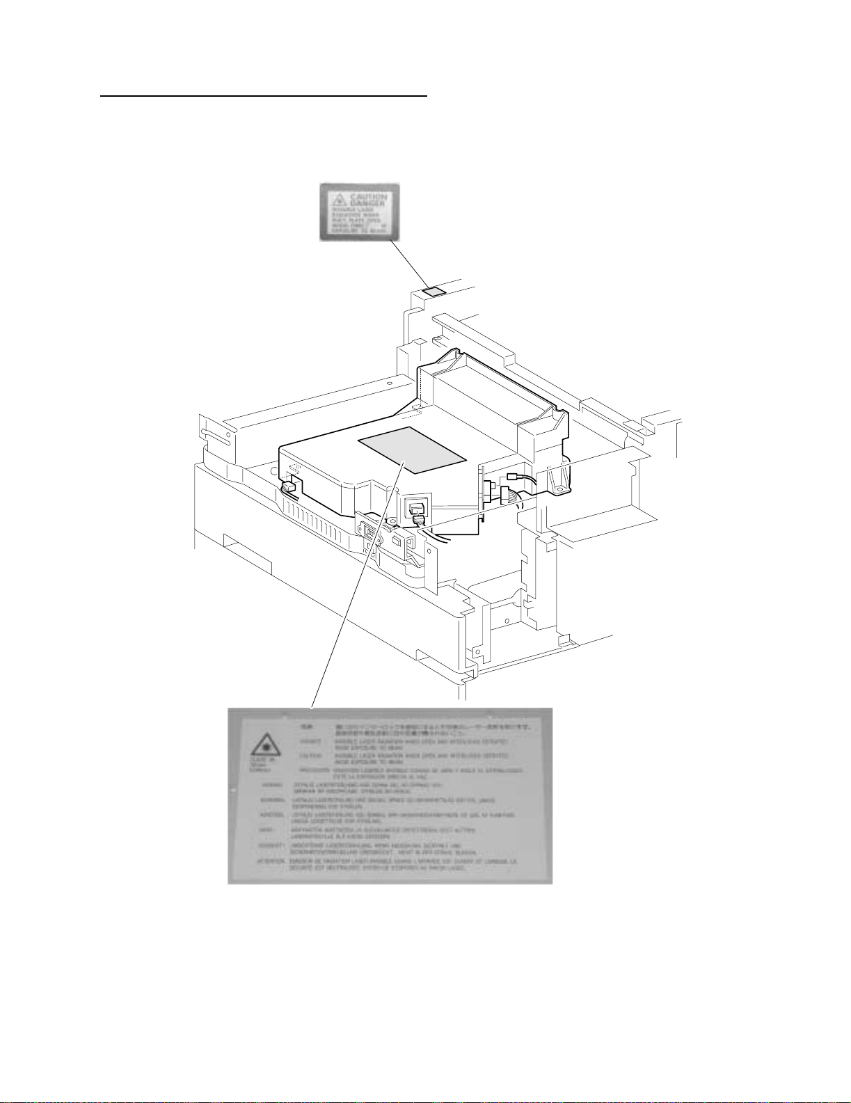
Notices and Safety Information
Laser Advisory and Caution Labels
Notices and Safety Information ix
Page 10
4025-XXX
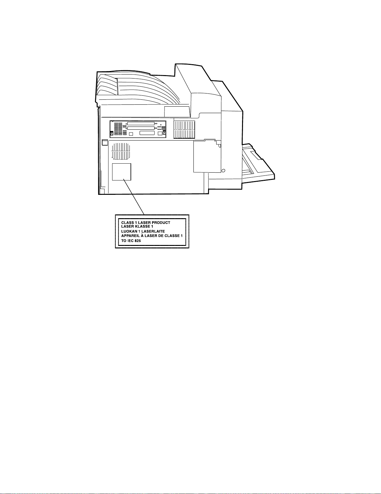
Class 1 Laser Statement Label
x Notices and Safety Information
Page 11

Laser Not ice s
Laser
4025-XXX
The printer is certified in the U.S. to conform to the requirements of DHHS 21 CFR
Subchapter J for Class I (1) laser products, and elsewhere is certified as a Class I laser
product conforming to the requirements of IEC 60825.
Class I laser products are not considered to be hazardous. The printer contains internally
a Class IIIb (3b) laser that is nominally a 5 milliwatt gallium arsenide laser operating in the
wavelength region of 770-795 nanometers. The laser syst em and printer are designed so
there is never any human access to laser radiation above a Class I level during normal
operation, user maintenance, or prescribed service condition.
Der Drucker erfüllt gemäß amtlicher Bestätigung der USA die Anforderungen der
Bestimmung DHHS (Department of Health and Human Se r v ices) 21 CFR Teil J für
Laserprodukte der Klasse I (1). In anderen Ländern gilt der Drucker als Laserprodukt der
Klasse I, der die Anforderungen der IEC (International Electrotechnical Commission)
60825 gemäß amtlicher Bestätigung erfüllt.
Laserprodukte der Klasse I gelten als unschädlich. Im Inneren des Druckers befindet sich
ein Laser der Klasse IIIb (3b), bei dem es sich um einen Galliumarsenlaser mit 5 Milliwatt
handelt, der Wellen der Länge 770-795 Nanometer ausstrahlt. Das Lasersystem und der
Drucker sind so konzipiert, daß im Normalbetrieb, bei der Wartung durch den Benutzer
oder bei ordnungsgemäßer Wartung durch den Kundendienst Laserbestrahlung, die die
Klasse I übersteigen würde, Menschen keinesfalls erreicht.
Avis relatif à l’utilisation de laser
Pour les Etats-Unis : cette imprimante est cert ifiée conforme aux provisions DHHS 21
CFR alinéa J concernant les produits laser de Classe I (1). Pour les autres pays : cette
imprimante répond aux normes IEC 60825 relatives aux produits laser de Classe I.
Les produits laser de Classe I sont considérés comme des produits non dangereux.
Cette imprimante est équipée d’un laser de Classe IIIb (3b) (arséniure de gallium d’une
puissance nominale de 5 milliwatts) émettant sur des longueurs d’onde comprises entre
770 et 795 nanomètres. L’imprimante et son système laser sont conçus pour impossible,
dans des conditions normales d’utilisation, d’entretien par l’utilisateur ou de révision,
l’exposition à des rayonnements laser supérieurs à des rayonnements de Classe I .
Avvertenze sui prodotti laser
Questa stampante è certificata negli Stati Uniti per essere conforme ai requisiti del DHHS
21 CFR Sottocapitolo J per i prodotti laser di classe 1 ed è certificata negli altri Paesi
come prodotto laser di classe 1 conforme ai requisiti della norma CEI 60825.
I prodotti laser di classe non sono considerati pericolosi. La stampante contiene al suo
interno un laser di classe IIIb (3b) all’arseniuro di gallio della potenza di 5mW che opera
sulla lun gh ez z a d’onda compresa tra 770 e 795 nanometri. Il sistema laser e la
Notices and Safety Information xi
Page 12

stampante sono stati progettati in modo tale che le persone a contatto con la stampante,
durante il normale funzionamento, le operazioni di servizio o quelle di assistenza tecnica,
non ricevano radiazioni laser superior i al livello della classe 1.
Avisos sobre el láser
Se certifica que, en los EE.UU., esta impresora cumple los requisitos para los productos
láser de Clase I (1) establecidos en el subcapítulo J de la norma CFR 21 del DHHS
(Departamento de Sa nidad y Ser vi cios ) y, en los demás países, reúne todas las
condiciones expuestas en la norma IEC 60825 para productos láser de Clase I (1).
Los productos láser de Clase I no se consideran peligrosos. La impresora contiene en su
interior un láser de Clase IIIb (3b) de arseniuro de galio de funcionamiento nominal a 5
milivatios en una longitud de onda de 770 a 795 nanómetros. El sistema láser y la
impresora están diseñados de forma que ningun a persona pueda verse afectada por
ningún tipo de radiación láser superior al nivel de la Clase I durante su uso normal, el
mantenimiento realizado por el usuario o cualquier otra situación de servicio técnico.
Declaração sobre La ser
4025-XXX
A impressora está certificada nos E.U.A. em conformidade com os requisitos da
regulamentação DHHS 21 CFR Subcapítulo J para a Classe I (1) de produtos laser. Em
outros locais, está certificada como um produto laser da Classe I, em conformidade com
os requisitos da norma IEC 60825.
Os produtos laser da Classe I não são considerados perigosos. Internamente, a
impressora contém um produto laser da Classe IIIb (3b), designado laser de arseneto de
potássio, de 5 milliwatts ,operando numa faixa de comprimento de onda entre 770 e 795
nanómetros. O sistema e a impressora laser foram concebidos de forma a nunca existir
qualquer possiblidade de acesso humano a radiação laser superior a um nível de Classe
I durante a operação normal, a manutenção feita pelo utilizador ou condições de
assistência prescritas.
Laserinformatie
De printer voldoet aan de eisen die gesteld worden aan een laserprodukt van klasse I.
Voor de Verenigde Staten zijn deze eisen vastgelegd in DHHS 21 CFR Subchapter J,
voor andere landen in IEC 60825.
Laserprodukten van klasse I worden niet als ongevaarlijk aangemerkt. De printer is
voorzien van een laser van klasse IIIb (3b), dat wil zeggen een gallium arsenide-laser van
5 milliwatt met een golflengte van 770-795 nanometer. Het lasergedeelte en de printer
zijn zo ontworpen dat bij normaal gebruik , bij onderhoud of reparatie conform de
voorschriften, nooit blootstelling mogelijk is aan laserstraling boven een niveau zoals
voorgeschrev en is voor klasse 1.
xii Notices and Safety Information
Page 13

Lasermeddelelse
Printeren er godkendt som et Klasse I-laserprodukt, i overenstemmelse med kravene i
IEC 60825.
Klasse I-laserprodukter betragtes ikke som farlige. Printeren indeholder internt en Klasse
IIIB (3b)- las e r, der nom ine lt er en 5 milli watt ga lliumars en id la s e r, som ar be jder på
bølgelængdeområdet 770-795 nanom eter. Lasersystemet og printeren er udformet
således, at mennesker aldrig udsættes for en laserstråling over Klasse I-niveau ved
normal drift, brugervedligeholdelse eller obligatoriske servicebetingelser.
Huomautu s las er laittees ta
Tämä kirjoitin on Yhdysvalloissa luokan I (1) l aserlaitteiden DHHS 21 CFR Subchapter J määrityksen mukainen ja muualla luokan I laserlaitteiden IEC 60825 -määrityksen
mukainen.
Luokan I laserlaitteiden ei katsota olevan vaar allisia käyttäjälle . Kir joittimessa on sisäinen
luokan IIIb (3b) 5 milliwatin gallium ar se nidil as er, joka toimii aaltoaluee lla 770 - 79 5
nanometriä. Laserjärjestelmä ja kirjoitin on suunniteltu siten, että käyttäjä ei altistu luokan
I määrityksiä voimakkaammalle säteilylle kirjoittimen normaalin toiminnan, käyttäjän
tekemien huoltotoimien tai muiden huoltotoimien yhteydessä.
4025-XXX
Laser-notis
Laser-melding
VARO! Avattaessa ja suojalukitus ohitettaessa olet alttiina näkymättömälle
lasersäteilylle. Älä katso säteeseen.
VARNING! Osynlig laserstrålning när denna del är öppnad och spärren är urkopplad.
Betra k ta e j s trålen.
Denna skrivare är i USA certifierad att motsvara krav en i DHHS 21 CFR, underparagraf J
för laserprodukter av Klass I (1). I andra länder uppfyller skrivaren kraven för
laserprodukter av Klass I enligt kraven i IEC 60825.
Laserprodukter i Klass I anses ej hälsovådliga. Skrivaren har en inbyggd laser av Klass
IIIb (3b) som består av en laserenhet av gallium-arsenid på 5 milliwatt som arbetar i
våglängdsområdet 770-795 nanometer. Lasersystemet och skrivaren är utformade så att
det aldrig finns risk för att någon person utsätts för laserstrålning över Klass I-nivå vid
normal användning, underhåll som utförs av användaren eller annan föreskriven
serviceåtgärd.
Skriveren er godkjent i USA etter kravene i DHHS 21 CFR, underkapittel J, for klasse I (1)
laserprodukter, og er i andre land godkjent som et Klasse I-laserprodukt i samsvar med
kravene i IEC 60825.
Notices and Safety Information xiii
Page 14

Klasse I-laserprodukte r er ik ke å betrakte som farlige. Skriveren inneholder internt en
klasse IIIb (3b)-laser, som består av en gallium-arsenlaserenhet som avgir stråling i
bølgelengdeområdet 770-795 nanometer. Lasersystemet og skriveren er utformet slik at
personer aldri utsettes for laserstråling ut ov er klasse I-nivå under vanlig bruk, vedlikehold
som utføres av brukeren, eller foreskrevne serviceoperasjoner.
Avís sobre el Làser
Segons ha estat certificat als Estats Units, aquesta impressora compleix els requisits de
DHHS 21 CFR, apartat J, pels productes làser de classe I (1), i segons ha estat certificat
en altres llocs, és un producte làser de classe I que compleix els requisits d’IEC 60825.
Els productes làser de classe I no es consideren perillosos. Aquesta impressora conté un
làser de classe IIIb (3b) d’arseniür de gal.li, nominalment de 5 mil.liwats, i funciona a la
regió de longitud d’ona de 770-795 nanòmetres. El sistema làser i la impressora han
sigut concebuts de manera que mai hi hagi exposició a la radiació làser per sobre d’un
nivell de classe I durant una operació normal, durant les tasques de manteniment
d’usuari ni durant els serveis que satisfacin les condicions prescrites.
4025-XXX
Safety Information
• This product is designed, tested and approved to meet strict global safety standards
with the use of specific Lexmark components. The safety features of some parts may
not always be obvious. Lexmark is not responsible for the use of other replacement
parts.
• The maintenance information for this product has been prepared for use by a
professional service person and is not intended to be used by others.
• There may be an increased risk of electric shock and personal injury during
disassembly and servicing of this product. Professional service personnel should
understand this and take necessary precautions.
Consignes de Sécurité
• Ce produit a été conçu, testé et approuvé pour respecter les normes strictes de
sécurité globale lors de l'utilisation de composants Lexmark spécifiques. Les
caractéristiques de sécurité de certains éléments ne sont pas toujours évidentes.
Lexmark ne peut être tenu responsable de l'utilisation d'autres pièces de rech ange.
• Les consignes d'entretien et de réparation de ce produit s'adressen t uniqueme nt à
un personnel de maintenance qualifié.
• Le démontage et l'entretien de ce produit pouvant présenter certains risques
électriques, le personnel d'entretien qualifié devra prendre toutes les précautions
nécessaires.
Norme di sicurezza
• Il prodotto è stato progettato, testato e approvato in conformità a severi standard di
sicurezza e per l’utilizzo con componenti Lexmark specifici. Le caratteristiche di
xiv Notices and Safety Information
Page 15

sicurezza di alcune parti non sempre sono di immediata co mpre nsione. Lexmark
non è responsabile per l’utilizzo di parti di ricambio di altri produttori.
• Le informazioni riguardanti la manutenzione di questo prodotto sono indirizzate
soltanto al personale di assistenza autorizzato.
• Durante lo smontaggio e la manutenzione di questo prodotto, il rischio di subire
scosse elettriche e danni alla persona è più elevato. Il personale di assistenza
autorizzato, deve, quindi, adottare le precauzioni necessarie.
Sicherheitshinweise
• Dieses Produkt und die zugehörigen Komponenten wurden entworfen und getestet,
um beim Einsatz die weltweit gültigen Sicherheitsanforderunge n zu erfüllen. Die
sicherheitsrelevanten Funktionen der Bauteile und Optionen sind nicht immer
offensichtlich. Sofern Teile eingesetzt werden, die nicht von Lexmark sind, wird von
Lexmark keinerlei Verantwortung oder Haftung für dieses Produkt übernommen.
• Die War tungs inform ationen für dieses Produkt sind ausschließlich für die
Verwendung durch einen Wartungsfachmann bestimmt.
• Während des Auseinandernehmens und der Wartung des Geräts besteht ein
zusätzliches Risiko eines elektrischen Schlags und körperlicher V erletzung. Das
zuständige Fachpersonal sollte entsprechende Vorsichtsmaßnahmen treffen.
•
4025-XXX
Pautas de Seguridad
• Este producto se ha diseñado, verificado y aprobado para cumplir los más estrictos
estándares de seguridad global usando los componentes específicos de Lexmark.
Puede que las características de seguridad de algunas piezas no sean siempre
evidentes. Lexmar k no se hace responsa ble del uso de otras piezas de recambio.
• La informac ión sobre el mantenimiento de este producto está dirigida
exclusivamente al personal cualificado de mantenimiento.
• Existe mayor riesgo de descarga eléctr ica y de daños personal es durante el
desmontaje y la reparación de la máquina. El personal cualificado debe ser
consciente de este peligro y tomar las precauciones necesarias.
Informações de Segurança
• Este produto foi concebido, testado e aprovado para satisfazer os padrões globais
de segurança na utilização de componentes específicos da Lexmark. As funções de
segurança de alguns dos componentes podem não ser sempre óbvias. A Lexmark
não é responsável pela u t iliz a ção de outros componentes de substituição.
• As informações de segurança relativas a este produto destinam-se a profissionais
destes serviços e não devem ser utilizadas por outras pessoas.
• Risco de choques eléctricos e ferimentos graves durante a desmontagem e
manutenção deste produto. Os profissionais destes serviços devem estar avisados
deste facto e tomar os cuidados necessários.
Notices and Safety Information xv
Page 16
Informació de Seguretat
• Aquest producte està dissenyat, comprovat i aprovat per tal d'acomplir les estrictes
normes de seguretat globals amb la utililització de compo nent s específi cs de
Lexmark. Les característiques de seguretat d'algunes peces pot ser que no sempre
siguin òbvies. Lexmark no es responsabilitza de l'us d'altres peces de recanvi.
• La informac ió pel manteniment d’aquest producte està orientada exclusivament a
professionals i no està destinada a ningú que no ho sigui.
• El risc de xoc elèctric i de danys personals pot augmentar durant el procés de
desmuntatge i de servei d’aquest producte. El personal professional ha d’estar-ne
assabentat i prendre les mesures convenients.
4025-XXX
xvi Notices and Safety Information
Page 17

Preface
4025-XXX
This manual describes the Lexmark
procedures for service personnel only. It is divided into the following chapters:
TM
W820 (4025-XXX) and contains maintenance
1. General Inf o rmation contains a general description of the printer and the
maintenance approach used to repair it. Special tools and test equipment are listed
in this chapter, as well as general environmental and safety instructions.
2. Diagnostic Information contains an error indicator table, symptom tables, and
service checks used to isolate failing field replaceable units (FRUs).
3. Diagnostic Aids contains tests and checks used to locate or repeat symptoms of
printer problems.
4. Repa ir Informatio n provides instructions for removing and installing FRUs.
5. Connector Locations uses illustrations to identify the connector locations and test
points on the printer.
6. Prevent ive Maintenanc e contains the lubrication specifications and
recommendations to prevent problems.
7. Parts Catalog contains illustrations and part numbers for individual FRUs.
Preface xvii
Page 18

4025-XXX
xviii Preface
Page 19

1. General Information
This service manual is written for the following products:
W820 printer (base) 4025-001
W820 printer (network) 4025-N01
Printer for X820e bundle* 4025-N01
Printer for X830e bundle* 4025-N02
Printer for X832e bundle* 4025-N03
* For scanner repair of the X820e, X830e or X832e, refer to the 4036-501 service manual.
Options
The following options are available for this printer :
4025-XXX
• Envelope Feeder
• Duplex
• Mailbox
• High Capacity Feeder
• Finisher
Service information for the Envelope Feeder, Duplex, Mailbox, and High Capacity Feeder
is contained in the Lexmark W820 Options Service Manual. Ser v ice information for the
Finisher is in the Lexmark W820 Finisher Service Manual.
Maintenance Approach
The diagnostic information in this manual leads you to the correct field replaceable unit
(FRU) or part for the printer. Use the error code table, symptom ser vice check table,
attendance message table, service checks, print quality service checks and symptom
service checks to determine the corrective action necessary to repair a malfunctioning
printer. After you complete the repair, perform tests as needed to verify the repair.
Tools Required For Service
The removal and replacement procedures described in this manual require the following
tools and equipment:
• Magnetic tip Phillips screwdrivers, large and small
• Flat-blade screwdrivers
• Analog volt ohmmeter (a digital volt ohmmeter may also be used)
General Information 1-1
Page 20
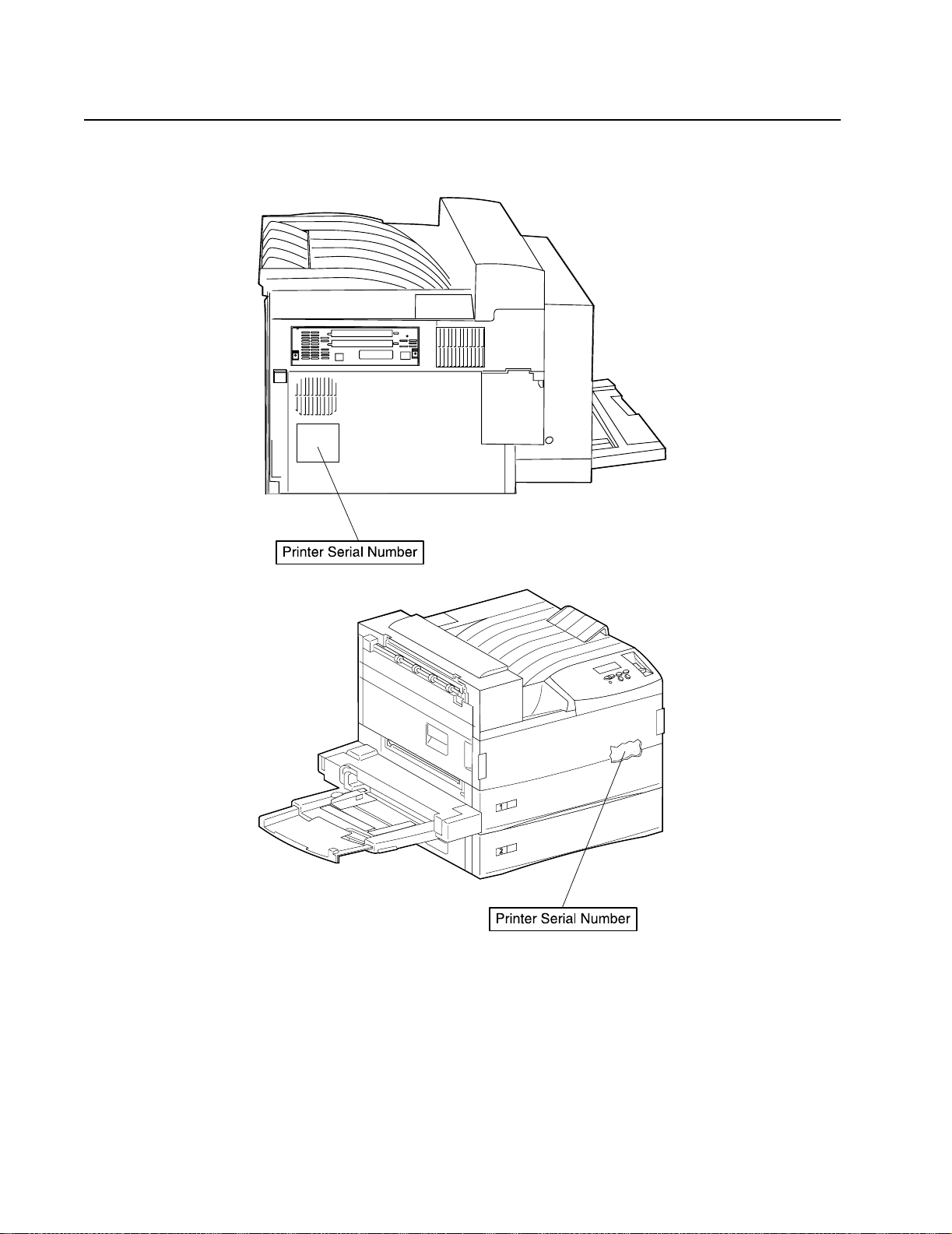
Serial Number Locations
Printer serial number labels are on the rear of the printer and inside the front cover.
4025-XXX
1-2 Service Manual
Page 21

Symbols Used in this Manual
Various symbols are used throughout this manual to either provide additional information
on a specific topic or to warn of possible danger that might be present during a procedure
or action. Be aware of all symbols when they are used, and always read NOTE,
CAUTION, and WARNING messages.
Note: A NOTE may indicate an operating or maintenance procedure, practice, or
condition that is necessary to efficiently accomplish a task. A NOTE may also provide
additional information related to a specific subject or add a comment on the results
achieved through a previous action.
WARNI NG: A WARNING indicates an operating or maintenance procedure, practice, or
condition that, if not strictly observed, could result in damage to, or destruction of,
equipment.
CAUTION: A CAUTION indicates an operating or maintenance procedure, practice, or
condition that, if not strictly observed, could result in injury.
Safety Details
4025-XXX
Follow all safety instructions to prevent accidents while servicing this printer. Always be
aware of the potential dangers that are present when you are working with electrical or
mechanical equipment.
Power Supply and Electrical Com ponents
Before starting any service procedure, switch off the printer power and unplug the power
cord from the wall outlet. If you must service the printer with power applied, be aware of
the potential for electrical shock.
CAUTION: Do not touch any electrical component unless you are instructed to do so by
a service procedure.
General Information 1-3
Page 22

4025-XXX
Mechanical Components
Manually rotate drive assemblies to inspect sprockets and gears.
CAUTIO N: Do not t ry to manually rotate or manually stop the drive assemblies while any
printer motor is running.
Laser Com p on ents
CAUTIO N: This printer generates a laser beam as part of the printing process. The laser
beam is a concentrated narrow beam of light that produces extreme heat at its focal point.
The laser beam in this printer is invisible. Although you cannot see the beam, it can still
cause severe damage. Direct eye exposure to the laser beam may cause eye injury or
blindness.
To avoid permanent eye damage, follow these directions:
• Before starting any service procedure, switch off the printer power and unplug the
power cord from the AC wall outlet.
• Do not disassemble the Printhead Assembly or any laser component that displays a
Laser Warning sticker.
• Use caution when you are working around the Printhead Assembly or when you are
performing laser related troubleshooting or repair procedures.
• Never place a mirror or a reflective tool or object in the laser beam path.
• Do not disassemble the printer in such a way that the laser beam can exit the print
engine during a print cycle.
Fuser Components
CAUTION: This printer uses heat to fuse the toner image to a sheet paper. The Fuser
Assembly is very hot. Switch off printer power and wait at least 45 minutes for the fuser to
cool before you attempt to service the Fuser Assembly or adjacent components.
Safety Components
Make sure covers and panel are in place and that all interlock s witches are all functioning
correctly after you have completed a printer service call. If you bypass, or cheat, an
interlock switch during a service call, use extreme caution when working on or around the
printer.
1-4 Service Manual
Page 23

Cautio n Labels
Throughout the printer, warning labels are displayed on potentially dangerous
components. When you service the printer, check to make sure that all caution labels are
in place.
Most importantly, read and obey all posted caution labels.
Service Flowchart
Included is a Service Flowchar t that outlines the approach to troubleshooting and repair
of the printer. The Service Flowchart is an overview of the path a service technician can
take, using this service manual, to service the printer.
Identify the problem. After you identify the problem, inspect and clean the printer (a
thorough cleaning frequently solves many printer problems). Continue down the
Flowchart in this manner, alway s retur ni ng to the next step in the Service Flowchart after
you complete the tasks outlined in the previous step.
If you choose not to use the Service Flowchart, we recommend that you start at the
appropriate Service Check and proceed from there.
4025-XXX
Identity the Problem
1. Verify that the reported problem does exist.
2. Check for any error codes and write them down.
3. Print three test prints.
4. Make note of any print quality problems in the test prints.
5. Make note of any unusual noise or smell coming from the printer.
Inspect and Cle an the Prin ter
Switch OFF printer power.
1.
2. Disconnect the AC power cord from the wall outlet.
3. Remove the EP Cartridge and shield it from strong light.
4. Inspect the printer interior and remove any foreign matter such as paper clips,
staples, pieces of paper, paper dust, or toner.
5. Clean the printer interior with a lint-free cloth, dampened slightly with cold water . Do
not use solvents or chemical cleaners to clean the printer interior. Do not use any
type of oil or lubricant on printer parts.
6. Clean all rubber rollers with a lint-free cloth that is dampened slightly with cold water.
Use a clean, dry , lint-free cloth to dry the rollers. Do not use solvents or chemical
cleaners to clean rubber rollers.
7. While you are cleaning, inspect the interior of the printer for damaged wires, loose
connections, toner leakage, and damaged or obviously worn parts.
8. If the EP Cartridge appears damag ed, replace it with a new one.
General Information 1-5
Page 24

Find the Cause of the Problem
1. Use the “Servi ce Flowchar t” on page 1-5 to find out how to use the Service
2. Use the “Servi ce Che cks” on pag e 2 -1 1 to check printer components.
3. Use the “Connector Locati ons” on page 5-1 to locate P/Js and test points.
4. Take voltage readings at various test points.
Correct the Problem
1. Use the “Par ts Ca talo g” on page 7-1 to locate the FRU number.
2. Use the “Removal and Replacement Procedures” on page 4-2 to replace a FRU.
Final Checkout
Test the printer to be sure you corrected the initial problem and there are no additional
problems.
Printer Overview
4025-XXX
Checks.
• Th e prin t er is a 45 page per minute (35 page per minute for X830e) black and white,
600 dots per inch laser printer that uses a data-modulated laser beam, standard dryink xerographic imaging processes, and heat and pressure fusing to place a
computer generated image onto the surface of a sheet of plain paper.
• The printer uses a semicon ducto r laser in the Pri nth ead to gene rate a 5 milli watt
infrared laser beam. Image data sent from the host computer modulates the beam,
creating a latent image on the surface of the electrically charged xerographic drum.
• The printer runs on 110VA C @ 60 Hz or 220VAC @ 50Hz using approximately 900
watts during an average print cycle. Two power supplies within the printer conv ert AC
line voltage to the various AC and DC voltages that are needed for printer operation.
• Safety circuits withi n the printer remove power to the printer whenever the Left Front
Cover is open or the EP Car tr idge is removed.
• The Machine Control Unit PWB (MCU PWB) controls all printer functions, houses
printer diagnostics, stores operating parameters, and signals printer errors.
• The ESS (Controller) PWB interfaces a host computer with the MCU PWB (Engine
Card).
• The printer has one Customer Replaceable Unit, or CRU, that the customer must
replace at specific intervals. That CRU is the EP Cartridge. The printer displays an
error code when it is time to replace the EP Cartridge.
1-6 Service Manual
Page 25
4025-XXX
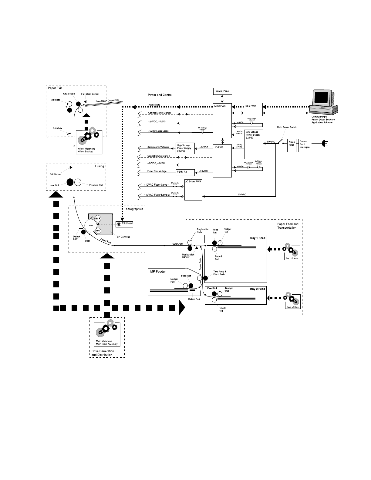
Schematic Diagram of Printer Operation
The following illustration is a simplified schematic of the printer components, subsystems,
and paper paths. Refer to individual sections of the Principles of Operation for greater
detail on specific areas.
General Information 1-7
Page 26

4025-XXX
Power and Control
The printer power cord plugs into an AC wall outlet. The other end of the power cord
plugs into the Noise Filter PWB, where the Filter removes fluctuations from the AC line
voltage. A Ground Fault Interrupter in the AC line protects the printer from electrical
shorts. With the Main Power Switch on, AC line voltage flows from the Noise Filter, and
into the Low Voltage Power Supply (LVPS) and into the AC Driver PWB. The LVPS
converts and distributes +5VDC and +24VDC voltages to the MCU PWB and I/O PWB.
The MCU PWB distributes +5VDC and +24VDC to the Printhead and various printer
components. The I/O PWB distributes +5VDC and +24VDC to various printer
components and distributes +24VDC to the High Volta ge Power Supply (HVPS) and to
the PSHV-R2 power supply. The HVPS converts the +24VDC supplied to it by the MCU
PWB into the high voltages that are used by the xerographic components of the printer.
The PSHV-R2 provides the Fuser Bias voltage. The AC Drive PWB distributes 110VAC
filtered line voltage to the two Fuser Heat Lamps.
The host computer, loaded with the correct printer driv er sof tw are, connects to the printer
through the ESS (Controller) PWB. The ESS PWB is connected to the MCU PWB. The
ESS PWB sends image data and process information to the MCU PWB. The MCU PWB
is the brain of the printer - housing printer parameters and timing tables, monitoring
printer operations, and controlling all printer functions. The MCU PWB monitors sensors
along the paper path, signaling the I/O PWB to switch components on and off, and
generates error codes whenever sensor statuses indicate a problem.
Drive Generation and Distribution
The printer base engine contains five motors. The MCU PWB controls all motor functions.
The Main Mot or supplies mechanical drive to the Main Drive Assembly. The Main Drive
Assembly and a series of individual gear clusters transfer drive throughout the printer.
The Drum Motor also supplies mechanical drive to the Main Drive Assembly. Electric
clutches control drive to specific components. Lift Motor 1 and 2 supply drive to Trays 1
and 2. The Offset Motor supplies drive to the Offset Rollers.
Xerographics
Xerographics consists of the Printhead which houses the laser, the EP Cartridge, and
the Bias Transfer Roll (BTR). Image data sent from the host computer to the MCU PWB
rapidly switches the laser on and off, shining onto the Drum and creating an invisible
electrical image on the surface of the electrically charged Drum. Dry ink, or toner,
transfers to the Drum surface, creating a visible toner image. The Drum, the Bias Charge
Roll (BCR), and the toner are all housed in the replaceable EP Car tri dge. When the
sheet of paper travels between the Drum and the electrically charged Bias Transfer R oll
(BTR), the toner image on the Drum transfers to the sheet of paper. The Detack Saw
helps remove the paper from the Drum.
1-8 Service Manual
Page 27

Printer Power
4025-XXX
Fusing
After image transfer, the toner image is not permanently fixed to the sheet of paper - it is
still dry power and can be easily rubbed off. The Fuser has two rotating rolls; the Hot Roll
and the Pressure Roll. A Lamp inside each of the Rolls heats the Fuser Rolls to
temperatures in access of 300
image melts and is pressed into the surface of the paper. Fuser Drive Rolls help move
the paper from the Fuser Rolls to the Exit Rolls. The Fuser Exit Sensor monitors the
sheet of paper leaving the Fuser.
°F. Paper passes between the two rolls where the toner
Paper E xit
Rolls in the O ffset and Exit Unit drive the sheet of paper out of the printer and into the
Face Down Output Tray or face up into the optional Duplex Module. The Full Stack
Sensor monitors the level of paper in the Fac e Down Output Tray.
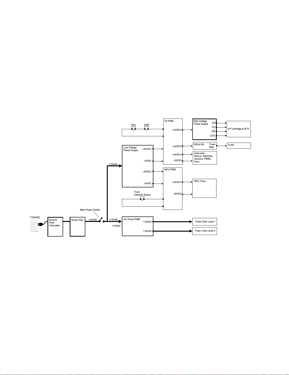
The power supplies in the printer provide the voltages that t he printer requires to operate.
The various printer functions require +5VDC, +24VDC, and several high voltage DC and
AC values that are used by xerographics.
The printer AC power cord plugs into a grounded AC wall outlet. The cord carries AC line
voltage to a Ground Fault Interrupter, then on to the Noise Filter PWB. The Noise Filter
smooths the AC voltage and sends it to the Main Power Switch. Switching on the Main
Power Switch applies AC voltage to the AC Driver PWB and to the Low Voltage Power
Supply (LVPS) PWB.
The AC Driver PWB is the interface between printer control (MCU) and the Fuser. Fuser
sensors connected to the AC Driver PWB send Fuser status information to the Driver
PWB, which the PWB routes to the MCU PWB. The MCU processes the information and
sends commands back to the AC Driver PWB to tell the AC Driver whether or not to
switch on the Fuser Heat Lamps.
The Low Voltage Power Supply PWB, or LVP S, converts the 110VAC to regulated
+24VDC and +5VDC voltages. The LVPS sends these voltages to the I/O PWB and to the
MCU PWB. The MCU uses the voltages for internal processing and for printer component
operation. The I/O PWB uses the voltages for printer component operation and also
sends +24VDC to the High Voltage Power Supply PWB.
The High V oltage Power Supply PWB, or HVPS, conver ts the +24VDC received from
the I/O PWB to the high voltages that are required by the xerographic system of the
printer. The HVPS produces the Charge (CR), Transfer (TR), Dev eloper Bias (DB), and
Detack (DTS) voltages, and sends them on to the EP Cartridge Detack Saw and to the
Bias Transfer Roll (BTR).
General Information 1-9
Page 28
4025-XXX
The PSHV-R2 converts the +24VDC received from the I/O PWB into the bias voltage
required by the Fuser.
Safety Interlocks for the printer are made up of two separate switches that are wired in
series with the I/O PWB and one switch that is attached to the MCU PWB. When the
Front Cover is open, the Front Cover Interlock Switch cuts +24VDC output from the
MCU PWB.
When the EP Cartridge is in place, Interlock Switch SW1 is closed. When the Left Hand
Cover is closed, Interloc k Swit ch SW2 is closed. With both switches closed, the circuit is
complete and the I/O PWB sends +24VDC to the HVPS and other printer components. If
either SW1 is open (the EP Cartridge removed) or SW2 is open (the Left Hand Cover is
open) the I/O PWB cuts all +24VDC output from the I/O PWB.
1-10 Service Manual
Page 29
4025-XXX
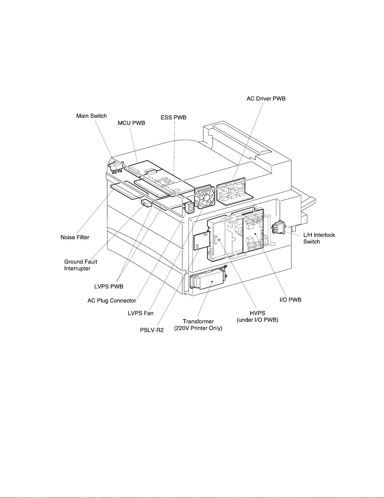
Power Supply Components
The printer Power Supply is made up of five major components and a number of
subcomponents.
1. Noise Filter PWB
Smooths and removes any fluctuation or hum from the AC line voltage.
Main Power Switch: Used to switch AC voltage on and off (switches the printer on
and off).
Ground Fault Interrupter (GFI): Used as a safety measure. If there is a short-
circuit, the GFI immediately cuts AC line voltage to the Noise Filter.
2. AC Dr ive r PWB
Receives smoothed AC voltage from the Noise Filter. The AC Driver PWB receives
Fuser temperature information from Fuser sensors and passes that information on to
the I/O PWB for processing. The MCU PWB signals the AC Driver to switch on or to
switch off AC voltage to the Fuser Heat Lamps.
General Information 1-11
Page 30

4025-XXX
3. Low Voltage Power Supply (LVPS)
Takes filtered AC voltage and converts it into regulated +24VDC and +5VDC.
The LVPS contains overcurrent protection circuits. If an excessive current begins
to flow through any of the components supplied by the LVPS, the LVPS immediately
shuts down all low voltage output. To reset the LVPS after an overcurrent shutdown;
switch off the printer, wait a few minutes, then switch on the printer.
The LVPS contains open circuit protection circuits. If the LVPS detects that a
circuit is open for longer than one minute, the LVPS slowly decreases the LVPS
output until the output is zero. To reset the LVPS after an open circuit shutdown;
switch off the printer, wait a few minutes, then switch on the printer.
The LVPS co ntains a low +24VDC output protection circuit. If the LVP S detects the
+24VDC output dropping below +15VDC, the LVPS slowly decreases the +24VDC
LVPS output until the output is zero.
LVPS Fan: A +24VDC fan that cools the LVPS PWB.
4. Machine Control Unit (MCU PWB)
Takes the +24VDC and +5VDC generated by the LVPS and distributes them to the
various components through out the printer, including the Printhead.
Front Cover Interl ock Swi t ch: Used as a safety measure. If the Interlock Switch is
closed (the Front Cover is closed) the MCU PWB sends +5VDC and +24VDC to
printer components. If the Interlock Switch is open (the Front Cover is open) the
MCU PWB cuts all +24VDC output.
5. I/O PW B
Takes the +24VDC and +5VDC generated by the LVPS and distributes them to the
various components through out the printer, including the HVPS.
Interlock Switches SW1 and SW2: Used as a safety measure. The main interlock
circuit for the printer is actually two separated switches wired in series with the I/O
PWB. When the EP Cartridge is in place, Interlock Switch SW1 is closed. When the
Left Front Cover is closed, Interlock Switch SW2 is closed. With both switches
closed, the circuit is complete and the I/O PWB sends +24VDC to the HVPS and
other printer components. If either SW1 is open (the EP Cartridge removed) or SW2
is open (the Left Front Cover is open) the I/O PWB cuts all +24VDC output.
CAUTION: Even though the interlock switches cut the +24VDC output from the MCU
PWB and I/O PWB, +24VDC output from the LVP S is still present throughout the printer
as well as 110VAC line voltage along the AC paths in the printer.
6. High Voltage Power Supply (HVPS)
Takes the +24VDC received from the I/O PWB and converts it into the high voltages
that are required by the printer xerographic components.
1-12 Service Manual
The HVPS contains overcurrent protection circuits. If an excessive current begins to
flow through any of the xerographic components, the HVPS immediately shuts down
all high voltage output. To reset the HVPS after an overcurrent shutdown; switch off
the printer, wait a few minutes, then switch on the printer.
Page 31

4025-XXX
7. PSHV-R2
Takes the +24VDC received from the I/O PWB and converts it into the Fuser Bias
voltage.
Electrical Safety Circuits
The printer contains three safety circuits that are controlled by three interlock switches
and one Ground Fault Interrupte r (GFI). Cutting power prevents a service technician or a
printer user from being injured by high voltage, by moving parts, or by exposure to the
laser beam.
SW1 (CRU Interlock Switch) is wired in series with SW2. SW1 is closed when the EP
Cartridge is in place inside the printer. When the EP Cartridg e is removed from the
printer, SW1 is open. An open SW1 cuts all +24VDC output from the I/O PWB.
SW2 (Left Cover Interlock Switch) is wired in series with SW1. SW2 is closed when the
printer Left Cover is closed. When the Left Cover is open, SW2 is open. An open SW2
cuts all +24VDC output from the I/O PWB.
If either SW1 or SW2 is open, the I/O PWB cuts all +24VDC output.
Front Cover Interl ock Swi t ch is connected to the MCU PWB. When the printer Front
Cover is open, the Interlock Switch cuts all +24VDC output from the MCU PWB.
Ground Fault Interrupter (GFI) senses minute amounts of current flowing to ground and
immediately cuts all AC line voltage into the Noise Filter. Faster than conventional circuit
breakers, the main purpose of the GFI is to prevent electrical shocks to the technician or
printer user.
CAUTION: It is dangerous to bypass, or cheat, either the CRU Interlock Switch or the
Left Cover I nterlock Switch while the EP Cartridge is out of the printer. With the interlocks
bypassed, the Laser Diode is active and generates intense laser light. Without the EP
Cartridge in place to block the laser beam, you risk serious eye injury.
General Information 1-13
Page 32

4025-XXX
I/O PWB
MCU PWB
HOT
N
+24VDC
+24VDC
Ground Fault Interrupter
SW1 (CRU Interlock)
SW2 (Left Cover Interlock)
Front Cover Interlock
Main Power Switch
EP Cartridge
Left Cover
Front Cover
Ground Fault
Interrupter
(GFI)
1-14 Service Manual
Left Front Cover
Interlock Switch
Page 33

Printer Control
4025-XXX
Printer control is a broad term that is used to describe the printer resources that monitor
and control the actions and operations of the print engine - from warm-up, through the
print cycle , t o machine error detection. T he ce nte r of printer control for the base engine is
the M
achine Control Unit PWB, or MCU PWB. The MCU PWB provides the logic and
information processing that is necessary for the printer to function. Almost every electrical
component within the printer is connected either directly or indirectly to the MCU PWB or
to the I/O PWB. The MCU polls the status of sensors in the printer and compares that
information to timing tables that are stored in onboard memory. Acting on the results of
the comparison, the MCU sends commands to various printer components or to the I/O
PWB; switching on motors, switching off voltages, signaling statuses. Non-Vol atile RAM
on the MCU PWB stores adjustable operation parameters, such as fuser temperature and
laser intensity, that are used as reference values during printer operation.
General Information 1-15
Page 34

4025-XXX
1-16 Service Manual
Page 35

4025-XXX
Printer Control Componen ts
The printer control is made up of the MCU PWB, the I/O PWB, and numerous connected
components.
Machine Control Unit PWB (MCU PWB)
The printer receives status and command information from the I/O PWB and from the
ESS PWB and controls most printer operations. The MCU PWB performs nine major
functions:
1. Communicates with the Printer Controller (ESS).
2. Maintains the system clock.
3. Controls the printing process.
4. Controls the Printhead, the Fuser, and the drive assemblies.
5. Distributes +5VDC and +24VDC to various printer components.
6. Monitors printer status.
7. Maintains a running print count.
8. Maintains NVRAM settings.
9. Controls printer options.
The ESS PWB is connected to the MCU PWB. Video data travels from the ESS PWB,
through the MCU PWB to the Laser Diode PWB.
General Information 1-17
Page 36

4025-XXX
Components attached to or associated with the MCU PWB:
1. I/O PW B
Interface between the MCU PWB and most of the printer components.
2. Low Voltage Power Supply
Converts AC line voltage to +5VDC and +24VDC.
3. ESS PWB
Connected to the MCU PWB. The interface between the print engine and the host
computer. The ESS processes the raw video data sent by the host computer.
4. Control Panel
Connected to the MCU PWB, the Control Panel displays status information sent from
the MCU PWB and ESS PWB.
5. AC Dr ive r PWB
Switches 110VAC to the two Fuser Heat Lamps. Fuser temperature sensors are
connected to the AC Drive PWB. The AC Drive PWB sends the temperature
information to the I/O PWB, which sends the information along to the MCU PWB.
6. High Voltage Power Supply
Converts +24VDC received from the I/O PWB to several high voltages that are
required by printer xerographics.
7. PSHV-R2
Converts +24VDC received from the I/O PWB to the Fuser bias voltage.
8. Toner Sensor
Magnetic sensor that monitors the CRU toner level.
9. CRU
Drum usage information that is stored in the CRU.
10. Printhead
The SOS (Start of Scan) Sensor, the Printhead Motor, and the Laser Diode.
11. Main Moto r
Provides most of the mechanical drive for the printer.
12. Drum Motor
Provides drive for the CRU.
13. Fuser Fan
Cools the Fuser area.
14. Feed Clutch
Transmits Main Motor drive to the Tray 1 Feed Rolls.
15. Registration Gate Clutch
Transmits Main Motor drive to the Registration Rolls.
1-18 Service Manual
Page 37

4025-XXX
16. Fuser Exit Sensor
Monitors paper travel out of the Fuser.
17. Face Up Exit Sensor
Monitors paper travel out of the Offset Unit.
18. Full Stack Sensor
Monitors the paper level in the Output Tray.
19. Exit Gate Solenoid
Tog g les the E x it Gate.
20. Inverter CW Clutch
Transmits Main Motor drive, forward, to the Offset Rolls.
21. Inverter CCW Clutch
Transmits Main Motor drive, reverse, to the Offset Rolls.
22. Offset Motor
Provides mechanical drive for the Offset Unit.
23. Duplex Module PWB
Provides +5VDC, +24VDC, and command and status lines to the Duplex PWB
option.
24. Mailbox
Provides +5VDC, +24VDC, and command and status lines to the Mailbox option.
25. Finisher
Provides +5VDC, +24VDC, and command and status lines to the Finisher option.
26. Envelope Feeder
Provides +5VDC, +24VDC, and command and status lines to the Envelope Feeder
option.
27. Cabinet Drive PWB
Provides +5VDC, +24VDC, and command and status lines to the High Capacity
Feeder option.
28. Size Sensor 1
Monitors the size of the paper that is loaded in Feeder 1. The Actuator Assembly
located at the rear of the Paper Tray has a series of cams that face the Size Sensor
PWB. Pushing the Paper Guide against the paper stack slides the Actuator
Assembly along a track. When the T ray is inserted into the Feeder, the cams on the
Actuator press the switches on the Size Sensor PWB in a pattern that is unique to
the position of the Paper Guide. The MCU PWB interprets this pattern as a specific
paper size.
General Information 1-19
Page 38

4025-XXX
29. Registration Sensor
Monitors paper travel out of the paper tray.
30. No Paper Sensor 1
Monitors the paper level in Feeder 1. When the Lift Motor raises the Bottom Plate,
the Plate raises the paper stack, the stack pushes the No Paper Actuator up and
away from the No Paper Sensor. The Sensor sends a paper present signal to the
MCU PWB. When the last sheet of paper is fed out of the Paper Tray, the No Paper
Actuator drops through a cutout in the Bottom Plate. The Actuator then blocks the
Sensor, and the Sensor sends a no paper signal to the I/O PWB - MCU PWB.
1-20 Service Manual
Page 39

4025-XXX
General Information 1-21
Page 40

4025-XXX
31. Level 1 Sensor
Monitor s wh ether or no t Tray 1 is installed. Installing the Tray pushes th e Link
Stopper out, which in turn lowers the Feed Roll and moves the Level 1 Sensor
Actuator tab away from the Sensor window.
32. MP Feeder Size Sensor
33. MP Feeder No Paper Sensor
34. MP Feeder Feed Clutch
1-22 Service Manual
Monitors the size of paper that is loaded in the MP Feeder.
Monitors the paper level in the MP Feeder.
Transmits Main Motor drive to the MP Feeder Feed Rolls.
Page 41

4025-XXX
35. Lift Motor 1
Raises the paper tray in Feeder 1. The MCU PWB switches on the Lift Motor. The
Motor rotates a square, metal shaft that is located inside the Paper Tray. The Shaft
raises the Tongue, which in turn raises the Bottom Plate, and the paper stack, up to
the Feed Rolls.
36. Take Away Roll Sensor
Monitors the paper travel at the Take Away Roll.
37. Interlock Switches 1 and 2
Monitors the CRU position Switch 1 and Left Cover Interlock Switch 2 on Feeder 1.
38. Feed Clutch 2
Transmits Main Motor drive to the Tray 2 Feed Rolls.
General Information 1-23
Page 42

4025-XXX
39. No Paper Sensor 2
Monitors the paper level in Feeder 2. Functions identical to No Paper Sensor 1.
40. Level 2 Sensor
Monitors whether or not Tray 2 is installed.
41. Size Sensor 2
Monitors the size of the paper that is loaded in Feeder 2.
42. Take Away Roll Sensor 2
Monitors the paper travel at the Take Away Roll 2.
43. Lift Motor 2
Raises the paper tray in Feeder 2.
44. Left C over Inte rlock 2
Monitors the Left Cover Interlock Switch on Feeder 2.
Control Functions of the Machine Control Unit (MCU)
1. Input from sensors
Sensors tell the MCU what is going on within the printer and what is happening to
the sheet of paper during a print cycle.
Example:
Printer sensors send their current status to the I/O PWB, which transfers the data on
to the MCU PWB. The sensor status signals tell the MCU whether they are actuated
or not a ctua te d (on or off, high o r low). If meas u r e d with a voltmeter, some senso r
signals to the MCU would be +5VDC when on and 0VDC when off, whil e o th e r
sensors may be 0VDC when on and +5VDC when off. In some cases, signal names
may indicate what reading you should get when the signal is on. For example, the
signal name PRINTHEAD MOTOR ON (L) 5VDC means when the Printhead M otor
signal is on, the reading goes low (0VDC), and when the Printhead Motor signal is
off, the reading goes high (5VDC).
1-24 Service Manual
Page 43

4025-XXX
2. Processing input information
Logic on the MCU compares the input information with the timing and reference
values that are stored in ROM and NVRAM on the PWB.
Example follows:
The Fuser Thermistor monitors the temperature of the Fuser Hot Roll and sends the
current temperature value to the I/O PWB. The I/O PWB relays the temperature data
to the MCU PWB. The MCU compares the current temperature with the set (or
expected) temperature that is stored in NVRAM on the MCU PWB. If the current
temperature is lower than the set temperature, the MCU sends a signal to the AC
Drive PWB to switch on the Fuser Heat Lamp until the current temperature reaches
the set temperature.
General Information 1-25
Page 44

4025-XXX
3. Output to motors, solenoids, and other components
After comparing input values with timing and reference values, the MCU makes a
decision on the current status of the printer and responds appropriately . The MCU
may switch on or off motors, solenoids, or other components. The MCU may also
signal that an error occurred.
Example follows:
At the start of a print cycle, the MCU switches on the Main Drive Motor, and then the
Feed Clutch. The MCU uses the Feed Clutch actuation as a timing marker. The Feed
Rolls attached to the Feed Clutch drive a sheet of paper out of the paper tray and
down the paper path. As the sheet of paper travels down the paper path it strikes the
Registration Sensor. The Sensor sends a signal to the MCU PWB telling it that the
paper has arrived. The MCU takes the elapsed time from when it actuated the Feed
Clutch to the time it received the signal from the Registration Sensor and compares
that time with the set time (or expected time) that is stored in ROM on the MCU
PWB. If the time elapsed is within range, the print cycle continues. If the time
elapsed is slower than the set time or if there was no signal from the Registration
Sensor within the set time, the MCU interprets that as an error and sends a 200
Registration Jam status to the ESS PWB.
1-26 Service Manual
4. Processing image data
Although the MCU PWB does control and monitor the operation of the Printhead, the
actual video data sent by a host computer bypasses the MCU PWB on its wa y to the
Laser Diode PWB.
Example follows:
Video data originating from either a local computer or a network computer enters
the printer through the ports in the ESS PWB. The ESS PWB stores and buffers the
raw data and then converts it to rasterized data tha t controls the Laser Diode. The
rasterized data leaves the ESS PWB and enters the MCU PWB. The MCU PWB
does not buffer nor process the data, it simply passes it along as a vid eo s i gnal to
the Laser Diode PWB. The video signal switches the Laser Diode on and off
according to the image information sent in the raw data.
Page 45

4025-XXX
General Information 1-27
Page 46

Mechanic al Dri ve
Mechanical Drive is a term that is used to describe both the rotation of the printer motors
and the action of the gear clusters and clutches that are used to transmit and control
motor rotation to the various components throughout the printer. The primary purpose of
Mechanical Drive within the base printer is to drive a sheet of paper out of a selected
paper tray, through the printer synchronous with the photo conductor surface and into an
output tray. The Printhead Motor is not considered part of Mechanical Drive.
The Main Drive Motor turns the Main Drive Assembly gears. The Drum Motor turns a
separate set of gears within the Main Drive Assembly. The Main Drive Motor and Drive
Assembly provide drive to the Feed Clutches, the Registration Clutch, the Fuser, and the
Exit Clutches. The Drum Motor and Drive Assembly provide drive to the Drum and BTR.
Lift Motors supply drive to each paper tray; raising the Bottom Plate of each tray so the
paper stack contacts the Feed Rolls. The Offset Motor provides drive to the Offset Rolls.
4025-XXX
1-28 Service Manual
Page 47

4025-XXX
Mechanical Drive Components
The mechanical drive is made up of the four major components.
1. Offset Motor
A +24VDC motor.
2. Main Drive A ssembly
Contains the +24VDC Main Drive Motor, the +24VDC Drum Motor, and the Main
Drive Assembly gears. The Main Motor and Drum Motor are attached to the Main
Drive Assembly.
3. Lift Motor 1
A +24VDC motor that raises Tray 1 bottom plate.
4. Lift Motor 2
A +24VDC motor that raises Tray 2 bottom plate.
General Information 1-29
Page 48

4025-XXX
Offset Motor
During Offset Mode, the MCU switches on the Offset Motor. The Offset Motor transmits
drive to the Offset Bracket. The Motor drives the Bracket toward the front of the printer,
pushing the Offset Roll along with it, until the Bracket reaches the end of travel, where it
stops. The MCU again switches on the Offset Motor, which drives the Bracket toward the
rear of the printer, carrying the Offset Roll along with it.
Main Motor and Main Drive Assembly
The MCU PWB switches the Main Motor on and off. The rotation of the Main Motor
creates mechanical drive.
The Main Drive Assembly gears transmit the motor drive to Feed Clutch 1, Feed Clutch 2,
and the MP Feeder Feed Clutch. At paper feed, the MCU PWB actuates a Feed Clutch,
which in turn transmits drive to the appropriate Feed Rolls.
The Main Drive Assembly gears transmit the motor drive to the Registration Clutch. At a
specific point in each print cycle, the MCU PWB actuates the Registration Clutch, which
in turn transmits drive to the Registration Roll.
The Main Drive Assembly gears transmit the motor drive to the Fuser Drive Gear. When
the Left Upper Cover is closed, the DTS Link Rod pushes the Fuser Drive Assembly into
contact with the Fuser Drive Gear, which transmits drive to the Fuser Rolls.
The Main Drive Assembly gears transmit the motor drive to the Exit Drive, which transmits
drive to the two Inverter Clutches. At a specific point in each print cycle, the MCU PWB
actuates either the CW Clutch or the CCW Clutch which drive the Exit Roll and the Offset
Roll.
Drum Motor and Main Drive Assembly
The MCU PWB s witc hes the Drum Motor on and off. The rotation of the Drum Motor
creates mechanical drive.The Main Drive Assembly gears transmit the motor drive to the
Drum. When the Drum Motor is on, the Drum rotates. When the Left Upper Cover is
closed, the BTR gear contacts the Drum gear, which in turn rotates the BTR.
Lift Motors 1 and 2
When a Paper Tray is installed in the printer, the MCU PWB switches on the Lift Motor.
Each tray has a square metal shaft running along one side of the tray . Attached to the
shaft is an L shaped metal tongue. When the tray is inserted into the paper feeder, a pin
at the end of the shaft engages the Lift Motor gear. When the MCU PWB switches on the
Lift Motor, the motor rotates the square shaft. The square shaft shifts the attached metal
tongue, which in turn raises the tray Bottom Plate which raises the paper stack. As the
paper stack raises, it pushes up on the No Paper Actuator, which in turn switches the No
Paper Sensor.
1-30 Service Manual
Page 49

4025-XXX
General Information 1-31
Page 50

4025-XXX
Printer Motor Control
The I/O PWB provides power to the Main Motor, Drum Motor, the Lift Motors, and the
Offset Motor. All motors run on +24VDC. The Main Motor and Drum Motor are stepper
motors. The MCU controls all motor operation. MCU signals step the Main Motor and
Drum Motor through a 360° rotation. The MCU PWB provides both forward and reverse
control of the Offset Motor.
1-32 Service Manual
Page 51

Paper Path
4025-XXX
Paper Path is the physical route that a sheet of paper takes through the printer during a
print cycle; from leaving the Paper Cassette to arriving at the Output Tray. Rubber rollers
and other components drive the paper along the Paper Path.
A sheet of paper may be fed from either T ra y 1, Tray 2, or from the MP Feeder. At the start
of a print cycle the Nudger Roll moves a sheet of paper into the Feed Roll. The Feed Roll
moves a single sheet of paper out of Tray 1/Tray 2/MP Feeder and toward the Registration
Roll. The Retard Rolls in Tray 1 and Tr a y 2 or the Retard Pad in the MP Feeder made sure
that only one sheet of paper is fed. If the paper was fed from Tray 2 or the MP Feeder the
Take Away Roll drives the paper to the Registration Roll. The Registration Roll aligns the
lead edge of the paper with the lead edge of the image on the drum. The Registration Roll
then drives the paper into the Drum/BTR area. The rotation of the Drum and BTR drive
the paper into the Fuser where the Heat and Pressure Rolls drive the paper into the
Offset/Pinch Roll. During simplex printing the Offset Roll drives the paper into the Output
tray. During duplex printing, the Offset Roll rotation is reversed and the Offset and Exit
Roll drives the paper into the Duplex Module.
General Information 1-33
Page 52

4025-XXX
1-34 Service Manual
Page 53

4025-XXX
Paper Path Components
The paper path is made up of a number of major components and subcomponents.
1. Tray Asse mbly
Holds plain paper of various sizes. Slides into the Feeder.
2. Feeder 1 and Feeder 2
Framework that is attached under the printer. A Tray Assembly slides into the
Feeder. The Feeder includes a number of paper feed components.
Lift Motor raises the Tray Bottom Plate so the paper contacts the Feed Roll.
No Paper Sensor mo nitors the level of paper in the Tray.
Paper Size Sensor monitors the size of paper in the Tray.
Feed Clut ch transmits drive to the Feed Roll and Nudger Roll.
Nudger Roll drives the top sheet of paper into the Feed Roll.
Feed Roll drives the top sheet of paper out of the Tray.
Retard Roll prevents multiple sheet feed.
Take Away Roll and Pinch Roll continue to drive the sheet of paper out of Tray 2
and toward the Registration Roll.
3. MP Feeder
Paper f eed assembl y that is attached to the outside of the printer. A small quantity or
paper, or the optional Envelope Feeder, fit on the MP Feeder foldout tray. The MP
Feeder includes a number of paper feed components.
MP Feeder N o Pape r Sensor monitors the level of paper in the MP Feeder tray.
MP Feeder Paper Size Sen sor monitors the size of paper in the Tray.
MP Feeder Feed Clut ch transmits drive to the Feed Roll and Nudger Roll.
Nudger Roll drives the top sheet of paper into the Feed Roll.
Feed Roll drives the top sheet of paper out of the MP Feeder tray.
Retard Pad prevents multiple sheet feed.
Take Away Roll and Pinch Roll continue to drive the sheet of paper out of the MP
Feeder Tray and toward the Registration Roll.
4. Registration Roll and Pinch Roll
The Registration Roll is a driven roll. The Pinch Roll is an idler that rides on the
surface of the Registration Roll. The Registration Roll and Pinch Roll register a sheet
of paper with the toner image on the surface of the Drum.
5. Registration Sensor
Monitors the movement of paper at the Registration Roll.
General Information 1-35
Page 54

4025-XXX
6. Drum and BTR (Bias Transfer Roll)
In addition to xerographic functions, the Drum and BTR drive the paper out of the
Xerographic area and into the Fuser area.
7. Hot Roll and Pressure Roll
In addition to fusing functions, the Hot Roll and Pressure Roll drive the sheet of
paper out of the Fuser and into the Offset Unit.
8. Fuser Exit Sensor
Monitors the movement of paper out of the Fuser.
9. Offset and Exit Unit
The assembly located above the Fuser. The Offset Unit drives paper to either the
standard Face Down Output Tray or to the Duplex Module. The Offset Unit includes a
number of components.
Inverter CW and CCW Clutches transmit Main Motor drive, forward and reverse, to
the Offset Rolls.
Offset Roll and Pinch Roll drive the sheet of paper either forward into the Output
Tray or in reverse to the Exit Roll and on to the Duplex Module.
Exit Gate Solenoid controls the Exit Gate to toggle the paper path between the
Output Tray or the Exit Roll and on to the Duplex Module.
Offset Motor and Offset Bracket moves the Offset Roll back and forth so paper
delivered to the Output Tray will stack offset.
Exit Roll and Pinch Roll drive the sheet of paper to Duplex Module.
Paper Path Mechanical Drive
The Main Drive Assembly provides the mechanical drive for the majority of the Paper
Path components. The Offset Motor provides the mechanical drive for the Offset Rolls.
1-36 Service Manual
Page 55

4025-XXX
Mechanical Drive for Paper Fed from the MP Feeder
The Main Motor provides mechanical drive for the MP Feeder. The Drive Assembly
transmits drive to the MP Feeder Feed Clutch. The MP Feeder Feed Roll and Nudger Roll
are attached to the MP Feeder Clutch. At paper feed, the MCU switches on the MP
Feeder Feed Clutch. The MP Feeder Feed Clutch transmits drive to the Feed Roll, which
rotates and begins feeding a single sheet of paper out of the MP Feeder Tray . Tray 1 Feed
Clutch transmits drive to the T ake A wa y Roll. The Take Away Roll and Pinch Roll drive the
sheet of paper into the Registration Roll.
General Information 1-37
Page 56

4025-XXX
Mechanical Drive for Paper Fed from Tray 1
The Main Motor provides mechanical drive for Tray 1 feed. The Drive Assembly transmits
drive to Tray 1 Feed Clutch. Tray 1 Feed Roll and Nudger Roll are attached to the Feed
Clutch. At paper feed, the MCU switches on Tray 1 Feed Clutch. The Feed Clutch
transmits drive to the Feed Roll, which rotates and begins feedi ng a single sheet of paper
out of Tray 1.
1-38 Service Manual
Page 57

4025-XXX
Mechanical Drive for Paper Fed from Tray 2
The Main Motor provides mechanical drive for Tray 2 feed. The Drive Assembly transmits
drive to Tray 2 Feed Clutch. Tray 2 Feed Roll and Nudger Roll are attached to the Feed
Clutch. At paper feed, the MCU switches on the Tray 2 Feed Clutch. The Feed Clutch
transmits drive to the Feed Roll, which rotates and begins feedi ng a single sheet of paper
out of Tray 2.
General Information 1-39
Page 58

4025-XXX
Mechanical Drive for Registration
The Main Motor provides mechanical drive for the Registration Roll. The Main Drive
Assembly transmits drive to the Registration Clutch. At a specific time in the print cycle
the MCU switches on the Registration Clutch to align the paper with the image on the PC
drum. The Registration Clutch transmits drive to the Registration Roll, which rotates and
drives the sheet of paper into the Drum/BTR area.
1-40 Service Manual
Page 59

4025-XXX
Mechanical Drive for the Drum and BTR
The Drum Motor provides mechanical drive for the Drum and BTR. The Main Drive
Assembly transmits drive to the Drum. A shutter covers and protects the Drum surface.
When the Left Cover is closed, a mechanical link opens the Shutter. When the Left Cover
is open, the link closes the Shutter. A gear attached to the end of the Drum transmits
drive to the BTR. Since the BTR is attached to the Left Cover Assembly , th e BTR is driven
only when the Left Cover is closed.
General Information 1-41
Page 60

4025-XXX
Mechanical Drive for the Fuser
The Main Motor provides mechanical drive for the Fuser Assembly. The Main Drive
Assembly transmits drive to the Fuser Drive Assembly and on to the Fuser Hot Roll Gear.
A gear at the end of the Hot Roll drives the Pressure Roll. The Heat and Pressure Rolls
rotates continuously while the Main Motor is on and the Left Front Cover is closed. Part of
the same mechanical link that opens and closes the Drum Shutter when the Left Cover is
closed, pushes the Fuser Drive Gear against the Fuser Hot Roll intermediate gear, which
transmits drive to the Fuser Hot Roll.
1-42 Service Manual
Page 61

4025-XXX
Mechanical Drive for Exit Drive
The Main Motor provides mechanical drive for the Offset and Exit Rolls. The Main Drive
Assembly transmits drive to the Inverter CW Clutch and to the Inverter CCW Clutch. At a
specific point in the print cycle the MCU switches on the CW Clutch. The CW Clutch
transmits forward drive to the Offset Roll, which drives the sheet of paper into the Face
Down Output Tray. If the printer is running in Duplex Mode, at a specific point in the
forward drive , the MCU switches off the CW Clutch and switches on the CCW Clutch. The
CCW Clutch transmits reverse drive to the Offset Roll and to the Exit Roll, which drive the
paper back across the top of the Fuser Assembly and into the Duplex Unit.
General Information 1-43
Page 62

4025-XXX
Mechanical Drive for Offset
The Offset Motor provides mechanical drive for the Offset Rolls. The Offset Motor
transmits drive to the Offset Bracket. If the printer is running in Offset mode, the MCU
switches on the Offset Motor. The Motor drives the Offset Bracket toward the front of the
printer. The Bracket pushes the Offset Roll along with it. The Offset Rolls drive one sheet
of paper into the Face Down Output Tray. The MCU switches the Offset Motor on again,
and the Motor drives the Offset Bracket back to the rear of the printer, taking the Offset
Roll with it. The Offset Rolls drive the next sheet of paper, slightly offset from the last
sheet, into the Face Down Output Tray.
1-44 Service Manual
Page 63

4025-XXX
Paper Path Component Control
The logic on the MCU PWB controls the Paper Path components. Sensors along the
paper path monitor the movement of each sheet of paper and send information back to
the MCU, through the I/O PWB. The MCU provides the timing and data processing
necessary to a ctuate clutches and solenoids, switch m otors o n a n d o ff, and to ide ntify
paper jams.
The I/O PWB provides +24VDC for the Main Motor, the Drum Motor, the Offset Motor,
and the assortment of clutches and solenoids within the pr inter. The I/O PWB also
provides +5VDC to the paper path sensors.
General Information 1-45
Page 64

Printhead
4025-XXX
The Printhead is the mechanism that performs Step 2. Expose of the print cycle.
A semiconductor within the Printhead Assembly generates a beam of laser light. Image
data received from the print controller modulates this beam, turning it on and off
according to image information that is received from the host computer. Through the use
of a series of rotating and stationary mirrors within the Printhead, the beam sweeps the
negative charged drum surface. Whenever the print controller sends a command to print
a black pixel, the laser switches on long enough to shine onto the drum at a single pixel
point. That point on the drum is now discharged.
1-46 Service Manual
Page 65

4025-XXX
Printhead Components
The Printhead Assembly is made up of one major component housing a number of subcomponents.
CAUTION: The Printhead generates a laser beam. The laser beam is a very powerful
and narrow beam of light that produces extreme heat at its focal point. The laser beam in
the printer is invisible. Although you cannot see the beam, it can still cause severe eye
injury. Never place a mirror or a reflective tool in the laser beam path. Never run the
printer with the covers removed or the interlocks bypassed.
Housed inside the Printhead Assembly:
1. Laser Diode Assembly (LD)
A semiconductor Laser Diode that generates a 5 milliwatt class 3B laser beam.
Circuity on the LD PWB maintains the laser output power at a constant level. The LD
PWB is electrically connected to the MCU PWB. The MCU provides power, control
circuitry, and the video data input supplied by the host computer.
2. Corrective Lenses and Angled Mirror
Four lenses, two small, one medium, and one wide, and an angled mirror focus the
laser beam and direct it toward the Polygon Mirror.
3. Polygon Mirror
A twelve-side rotating mirror that is attached to the Scanner Motor Assembly. The
movement of the rotating Polygon Mirror reflects the laser beam in a sweeping
motion, from side to side across and through the wide lens.
4. Scanner Motor Assembly
The Scanner Motor Assembly is attached to the Scanner Motor Assembly PWB. The
+24VDC Motor rotates at a constant speed. The Scanner Motor Assembly is
electrically connected to the MCU.
5. Wide Lens
A lens that focuses the beam coming from the Polygon Mi rror and directs it onto the
Angled Mirror.
6. Drum Mirror
Angled so it reflects the laser beam coming from the Angled Mirror, down onto the
surface of the drum.
7. SOS PWB (Start Of Scan Sensor)
The SOS Sensor is in-line with the laser beam sweep. The laser beam strikes the
SOS Sensor at the beginning of each sweep to let the printer control circuity know
that a new scan has started. The SOS PWB is electrically connected to the MCU
PWB.
General Information 1-47
Page 66

4025-XXX
Printhead Operation
The MCU PWB supplies +5VDC to drive the Laser Diode semiconductor. The
semiconductor uses the +5VDC to generate a 5 milliwatt beam of invisible laser light.
As is characteristic of semiconductor devices, the Laser Diode can switch states very
rapidly. A switching circuit on the Laser Diode PWB switches the Laser Diode on and off
according to i mag e da ta sent fro m the ESS Mother PWB.
Two lenses, an angled mirror, and another two lenses focus the laser beam onto the
rotating Polygon Mirror. The Polygon Mirror has twelve mirrored sides and rotates at
approximately 15,000 RPM. The Polygon Mirror reflects the laser beam back through the
two lenses and onto the Angled Mirror. The movement of the Polygon Mirror reflects the
laser beam in a sweeping motion, from side to side, across the Angled Mirror; with one
complete sweep for each mirrored side.
The Angled Mirror reflects the laser beam onto the Drum Mirror. The Drum Mirror is
aligned at an angle so the mirror reflects the sweeping beam down onto the surface of the
Drum. The combination of the rapid sweeping of the laser beam across the surface of the
charged Drum and the rapid switching on and off of the l aser beam creates, on the Drum,
an invisible electrical image that corresponds to the screen image that was sent from the
host computer. Located at one corner of the Printhead, near the end of the Angled Mirror
is the Start of Scan Sensor (SOS) Mirror. The Start of Scan Sensor is located at the
opposite corner of the Printhead Assembly. Each sweep of the laser beam begins by
striking the SOS Mirror, reflecting the beam into the SOS Lens, which focuses the beam
onto the SOS Sensor. The SOS Sensor is electrically connected to the MCU PWB. When
the laser beam strikes the Sensor, the Sensor notifies the MCU that a new scan has
started.
1-48 Service Manual
Page 67

4025-XXX
Image Resolution
The printer has an adjustable print image resolution of 600 dpi (dots per inch). Print
image resolution is determined by the number of dots (or pixels) per inch of beam sweep
and the number of sweeps per inch of paper travel. In the case of the 600 dpi image
resolution, there is a total of 600x600, or 360,000, separate pixels per square inch of
printed image.
General Information 1-49
Page 68

4025-XXX
Printhead Control
The Laser Diode PWB controls laser power monitoring and adjustment. The MCU PWB
controls the rest of the Printhead Assembly functions. The ESS PWB processes video
data sent from a host computer. The ESS PWB then passes that data on to the MCU
PWB which controls the flow of video data to the Laser Diode PWB. The MCU PWB
switches the laser diode on and off according to the image data being sent from the ESS
PWB. When the data signals for a black pixel, the MCU PWB rapidly switches the Laser
Diode on and off.
The MCU PWB provides the +5VDC needed to drive the Laser Diode. The CRU Interlock
Switch cuts +5VDC to the Laser Diode when the EP Cartridge is not in place in the
printer. The MCU PWB provides the +24VDC needed to run the Printhead Motor. The
MCU PWB also provides the signal (/RMOT ON) that switches the Printhead Motor on
and off. To reduce Printhead Motor wear, the MCU switches off the Printhead Motor after
15 minutes of printer inactivity.
The MCU PWB provides the +5VDC (signal 5V) needed by the SOS Sensor. The Sensor
uses the /SOS signal to return information about the start of each scan to the MCU PWB.
1-50 Service Manual
Page 69

4025-XXX
Laser Hazards
Lasers generate a very powerful beam of light that produces extreme heat at its focal
point. The laser beam that the Printhead generates is invisible. Although you cannot see
the laser beam, direct eye contact with the beam will cause se rious eye injury.
CAUTION: Always follow the laser service safety rules and use good judgement when
working on the printer.
Printhead Safeguards
There are two safety interlocks built into the CRU cavity.
A molded tab located at the end of the EP Cartridge actuates Interlock SW1 which,
along with SW2 (the Left Cover Interlock), controls +24VDC out of the MCU PWB. When
the Left Cover is open or the EP Cartridge is removed, SW1 and SW2 cut +24VDC out of
the MCU PWB.
An electrical jack at the end of the EP Cartridge completes the +5VDC circuit for CRU
Interlock switches SW1 and SW2. W hen the EP Cartridge is removed, +5VDC to the
Laser Diode is cut.
CAUTION: Never run the printer with the covers open or removed, the Main Interlock
Switch actuated, and/or the CRU Interlock Switches bypassed. Direct eye e xposure to the
laser beam may cause serious eye injury.
General Information 1-51
Page 70

Xerographics
4025-XXX
Xerographics and the Print Cycle
The printer xerographics is represented by steps 1 through 5, and steps 7 and 8 of the
print cycle.
The seven Xerographic steps (Step 6 Fuse is not part of the Xerographic cycle) in the
print cycle are:
1. Charge
Places a uniform negative electrostatic charge on the surface of the drum.
2. Expose
A data modulated laser beam scans the drum surface, converting select negative
points to positive points.
3. Develop
Attaches dry toner to the positive points of the drum.
4. Transfer
Transfers the dry toner image from the drum to a piece of paper.
5. Detack
Strips the piece of paper, along with the dr y toner image on the pape r surface, from
the drum.
6. Clean
Cleans any residual toner from the surface of the drum and prepares the drum for
the next print cycle.
7. Discharge
Cleans any residual electrical charge from the surface of the drum and prepares the
drum for the next p rint cycle.
1-52 Service Manual
Page 71

4025-XXX
Xerographics Overv iew
Xerography is the process of using an electrically charged surface and a dry, powered ink
to create an image on a sheet of plain paper. Xerography, in some form, is used in most of
today’s copiers and laser printers. The printer uses a number of components and AC and
DC voltages in its xerographic process.
The surface of the Drum is made of a photoconduct ive material that retains an electrical
charge as long as the material is not exposed to light. Exposure to light discharges the
electrical charge. At the start of each print cycle the BCR (Bias Charge Roll) places a
uniform electrical charge on the surface of the Drum. The modulated Laser Beam shines
light onto the surface of the drum , discharg ing select areas, thus creating an invisible
latent image. The latent image is made up of a pattern of negative and positive charges.
The Magnet Roll applies dry toner to the latent image to create a visible developed
image. A sheet of paper passes between the Drum and the BTR (Bias Transfer Roll)
where the developed image on the drum is transferred to the paper. The DTS (Deta ck
Saw) applies a voltage to the back of the paper to remove it from the Drum. The sheet of
paper, now with a toner image on the surface, moves out of the Xerographic area and on
to the Fuser. The Cleaning Blade scrapes any residual toner left on the Drum after
transfer and deposits it in a sealed reservoir that is located inside the EP Cartridg e.
General Information 1-53
Page 72

4025-XXX
Xerographic Components
Xerographics in the printer is made up of ten major components. Six of those
components are housed inside the EP Cartridge. The EP Cartridge is a sealed unit that
contains no field replaceable parts. The EP Cartridge is a CRU (Customer Replaceable
Unit) with an estimated life of 23,000 prints; assuming 5% image c overage of a standard
sheet of A4 paper.
Attached to the Transport Chute:
1. BTR (Bias Transfer Roll)
The BTR transfers the toner image from the drum to the sheet of paper. The BTR
rotates during the print cycle.
2. DTS (Detack Saw)
The DTS helps strip the sheet of paper off of the Drum.
Support components:
3. Toner Sensor
The Toner Sensor is a magnetic sensor that monitors the level of toner remaining
inside the EP Cartridge. The Toner Sensor is attached to the printer frame, inside the
EP Cartridge cavity, and is electrically connected to the MCU PWB.
4. High Voltage Power Supply PWB
Supplies all of the voltages used by the Xerographic components.
Housed inside the EP Cartridge:
5. Drum
The Drum is a hollow aluminum cylinder that has a surface coating of a
photoconductive material. The Drum rotates during the print cycle.
6. Bias Charge Roll (BCR)
The BCR places a uniform DC electrical charge on the surface of the drum. During
the print cycle, the BCR applies an AC voltage to the surface of the drum to
neutralize any electrical patterns remaining from the previous print cycle. The BCR
rotates during the print cycle.
7. Magnet Roll
The Magnet Roll collects toner from the toner reservoir and distributes it to the drum.
The Magnet Roll rotates during the print cycle.
8. Charge Metal Blade (CM Blade)
The CM Blade spreads an even coating of toner across the Magnet Roll. The CM
Blade also gives the Roll a static–el ectri c char ge.
1-54 Service Manual
Page 73

4025-XXX
9. Cleaning Blade
The Cleaning Blade rides the surface of the rotating drum, removing any residual
toner left from the previous print cycle.
10. Drum Shutter
The Drum Shutter protects the drum from damage by light or contamination. When
the EP Cartridge is in the printer and the Left Upper Cover is closed, the Drum
Shutter opens to expose the drum surface. When the EP Cartridge is out of the
printer or the Left Upper Cover is open, the Drum Shutter closes.
General Information 1-55
Page 74

4025-XXX
Xerographic Process During a Print Cycle
1. Charge
The Bias Charge Roll (BCR) places a uniform negative electrostatic charge on the
surface of the drum. The drum surface is made of a photoconductive material that
holds an electrical charge as long as the drum remains in darkness. Light striking
the drum discharges the surface charge.
The BCR is a conductive roll that is positioned slightly above the surface of the drum.
The HVPS supplies the BCR with two voltages; a negative DC charge voltage and
an AC discharge voltage that is used for electrically cleaning the drum (discussed in
Step 6. Clean).
1-56 Service Manual
2. Expose
The Printhead generates a beam of laser light. Image data received from the print
controller modulates this beam, turning it on and off according to image information
that is received from the host computer and software.
Through the use of a series of rotating and stationary mirrors within the Printhead,
the beam scans the negative charged drum surface. Whenever the print controller
sends a command to print a black pixel, the laser switches on long enough to shine
onto the drum at a single pixel point. That point is now discharged and slightly less
negative than the surrounding negative charge. The less negative areas are
considered positive. This discharge/no discharge process creates an invisible,
electrostatic image on the surface of the drum. This image is called a latent image.
Page 75

4025-XXX
The Printhead also helps to clean and prepare the drum by scanning the surface of
the drum at the beginning of each individual printer cycle. This action discharges an
residual DC charge that may still remain on the Drum from the last print cycle.
3. Develop
The toner contained within the EP Cartridge has a magnetic property that causes it
to adhere to the Magnetic Roll. The Charge Metering Blade (CM Blade) spreads the
toner into a very thin layer on the Magnetic Roll. Friction between the Magnetic Roll
and the CM Blade generates a small electrical charge that is transferred to the toner.
The surface of the Magnetic Roll is made up of a thin sheet of conductive material.
The HVPS supplies the Magnetic Roll with two voltages; a DC voltage and an AC
voltage. The DC voltage is used to transfer toner from the Magnetic Roll to the
surface of the drum. The AC vol tage agitates the t oner on the Magnetic Roll, making
toner transfer easier.
The Magnetic Roll maintains a negative DC electrical potential. Negative charged
areas of the drum have a lower electrical potential, or higher relative negative value
than the Magnetic Roll. Discharged areas of the drum have a higher electrical
potential, or lower relative negative v alue, than the Magnetic Roll. A discharged point
on the surface of the drum now appears less negative in relation to the negative
charge on the Magnetic Roll.
General Information 1-57
Page 76

4025-XXX
The toner adhering to the Magnet Roll is always in contact with the drum surface.
When a less negative point on the drum (a discharged area) comes in contact with
the more negative charged toner on the Magnet Roll, toner transfers from the
Magnet Roll to that point on the drum. There is now a visible toner image on the
drum surface. The image is called a developed image.
1-58 Service Manual
Page 77

4025-XXX
4. Transfer
As the paper travels between the BTR and the drum surface, the Bias T ransfer Roll
(BTR) applies a positive charge to the back of the printing paper. This positive
charge transfers the negative charged toner image from the drum surface to the top
surface of the paper. The toner image is now on the paper and the paper is now
stuck to the drum surface, due to the relative electrical differences between the
negative electrical charge of the inner conductive layer of the drum and the positive
electrical charge of the paper.
General Information 1-59
Page 78

4025-XXX
5. Detack
After the toner image transfers to the surface of the paper, the Detack Saw (a thin
strip of metal that resembles a saw blade) applies a low voltage negative charge to
the back of the paper to neutralize the positive voltage that was applied to it by the
BTR. Once the positive voltage is neutralized, the paper strips releases easily from
the drum surface and continues along the paper path to the Fuser.
6. Clean
The Cleaning Blade removes any toner that remains on the drum after the transfer
process. The toner that the Cleaning Blade removes is collected inside the sealed
EP Cartridge. Toner that is reclaimed from the drum is not reused by the EP
Cartridge.
1-60 Service Manual
Page 79

4025-XXX
7. Discharge
At both the start and the end of each individual printer cycle the HVPS supplies the
BCR with an AC voltage that is used to electrically clean the drum. The AC voltage
removes any residual DC charge that was left from the previous print cycle.
At the beginning of each individual printer cycle the Printhead scans the surface of
the drum, further discharging any residual DC charge that may be left on the drum.
Mechanical Drive f o r Xerographics
The Drum Motor and the Main Drive Assembly provide the mechanical drive for the Drum
and the BTR.
The mechanical energy created by the Drum Motor is transmitted through the Main Drive
Assembly to a drive pin that is located at the rear of the Assembly. When the EP
Cartridge is in place, the Drum engages the pin. A gear attached to the end of the Drum
drives the BTR.
Xerographic Control
The logic on the MCU PWB controls all Xerographic functions. The High Voltage Power
Supply (HVPS) provides all of the Xerographic voltages.
HVPS
The I/O PWB supplies +24VDC to the HVPS. The HVPS converts the +24VDC to the
Xerographic voltages. The HVPS provides CR (Charge Voltages), DB (Developer Bias
Voltages), TR (Transfer V ol tage), DTS (Detack Saw Voltage), and RTN (Return). The
logic on the MCU PWB uses a number of signals to the HVPS to switch on the various
Xerographic components.
General Information 1-61
Page 80

4025-XXX
Toner Sensor
The Toner Senso r is electrically conne cted to the MCU PWB through the I/O PWB. The
logic on the MCU PWB uses the NO TONER signal to monitor the level of unused toner
inside the EP Cartridge. When the NO TONER signal goes low , the MCU PWB logic waits
for ten additional print cycles to complete, then it generates a 88 Toner low message.
Image Quality Control - The Toner Sensor
The printer uses a Tone r Sensor to help maintain consistent print imag e quality. The
Sensor mounts on the printer frame, under and against the EP Cartridge. The Sensor is
magnetic sensitive and it monitors the level of unused toner inside the EP Cartridge.
When the toner level reaches a specific point, the Sensor notifies the MCU PWB. The
MCU then sends out a 88 Toner Low message.
1-62 Service Manual
Page 81

4025-XXX
8. Fusing
Image fusing is the sixt h st ep of the print cycle.
When a sheet of paper leaves the transfer area, static electricity holds the unfused toner
image to the surface of the paper. After transfer, the paper moves to the Fuser where it
passes between the Hot Roll and the Pressure Roll. The combination of heat and
pressure melts the toner image and bonds it permanently to the paper. The fused sheet
of paper is then transported to the output tray.
General Information 1-63
Page 82

4025-XXX
Fuser Components
The Fuser Assembly is made up of seven major components:
CAUTIO N: The Fuser can be extremely hot. Be careful when working with or around the
Fuser Assembly. Switch off the printer and wait until the Fuser has cooled before
attempting to remove or disassemble it.
1. Heat Lamp 1 (Main)
Heat Lamp 1 is a quartz lamp that is suspended inside the Hot Roll. When the AC
Drive switches AC voltage to Heat Lamp 1, the Lamp heats up and in turn heats up
the Hot Roll.
2. Heat Lamp 2 (Sub)
Heat Lamp 2 is a quartz lamp that is suspended inside the Hot Roll. When the AC
Drive switches AC voltage to Heat Lamp 2, the Lamp heats up and in turn heats up
the Hot Roll. Heat Lamp 2 switches on during a print cycle.
3. The Hot Roll
The Hot Roll is a hollow aluminum tube that is coated with a non-stick surface. The
Heat Lamp heats the Hot Roll to a temperature sufficient enough to melt dry toner.
There is a drive gear attached to one end of the Hot Roll. The Hot Roll rotates
against the Pressure Roll.
4. The Pressure Roll
The Pressure Roll is a metal shaft that is surrounded by a hard rubber roll. The ends
of the shaft rest in spring-loaded bearings. The Hot Roll presses against the
Pressure Roll. During the fusing step, paper passes between the rotating Hot Roll
and the rotating Pressure Roll.
5. The Thermistor (STS)
The Thermistor is a heat sensitive resistor [STS] that gently rides on the surface of
the Hot Roll. The Thermistor monitors the surface temperature of the Hot Roll and
sends information back to the I/O PWB and on to the MCU PWB. According to the
temperature information received, the MCU PWB either switches on or switches off
the Heat Lamp.
If the Fuser begins to overheat, the Thermistor functions as the first-stage overheat
protection; signaling the MCU PWB to cut all AC power to the Heat Lamp.
6. The Fuser Thermostat
The Fuser Thermostat is connected in series with the Heat Lamp AC circuit. The
Thermostat functions as the second-stage overheat protection. If the Te mpe rature
Sensor fails to shutdown AC power to the Fuser, at a specific temperature the
Thermostat opens the AC circuit between the Power Supply and the Heat Lamp.
7. The Fuser Fuse
The Fuser Fuse is connected in series with the Heat Lamp AC circuit. The Fuse
functions as the third-stage overheat protection. If the Fuser Thermostat fails to
shutdown AC power to the Fuser, at a specific temperature the Fuser Fuse opens
the AC circuit between the Power Supply and the Heat Lamp.
1-64 Service Manual
Page 83

4025-XXX
Mechanical Drive for the Fuser Assembly
The Main Drive Motor, the Mai n Drive Assem bly, and the Fuser Drive Assembly
provide the mechanical drive for the Fuser Assembly.
The Main Drive Assembly transmits drive to the Fuser Drive Gear.
General Information 1-65
Page 84

4025-XXX
When the Left Upper Cover is closed, the DTS Link Rod pushes the Fuser Drive
Assembly into contact with the Fuser Drive Gear, which transmits drive to the Hot Roll
Gear. The Hot Roll rotates and transmits drive through a Pressure Roll Gear to the
Pressure Roll.
1-66 Service Manual
Page 85

4025-XXX
Fuser Control
Logic circuits on the MCU PWB and relays on the AC Drive PWB control all Fuser
functions.
General Information 1-67
Page 86

4025-XXX
Thermistor (STS)
The Thermistor monitors the surface temperature of the Hot Roll and sends information
back to the MCU PWB through the I/O PWB. According to the temperature information
received, the MCU PWB commands the AC Driver PWB to either switch on or switch off
the Heat Lamps. The Thermistor is marked STS on the circuit schematic.
Heat Lamp Main
Logic on the MCU uses the /MAIN HEAT signal the AC Drive t o apply 110VC to switch on
the Main Heat Lamp.
Heat Lamp Sub
Logic on the MCU uses the /SUB HEAT signal the AC Drive to apply 110VC to switch on
the Sub Heat Lamp.
Fuser Fan
The MCU PWB controls the Fuser Fan and the alarm signal that indicates the Fan is not
rotating.
1-68 Service Manual
Page 87

4025-XXX
General Specifications
Category Specification for product
Standard configuration Print Engine with Tray 1 (500 sheet), Tray 2 (500 sheet), MP
Feeder (50 sheet), and the Offset Unit
Printing method Xerography
Exposure method Data modulated (off/on) laser beam
Laser specifications Class 3B, 5 milliwatt semic onduc t or lase r dio de
Resolution of printed image 600 dpi (dots per inch)
Development method Mono Component Dry Toner
Fusing method Heat and pressure
Warm-up time From either a cold start or from sleep mode (with an ambient
temperature of 22°C) to Ready to Print within 1 minute
Power supply requirements 110V printer: 100 /115VAC (±10%) @ 50/60 Hz (±3 Hz)
240V printer: 220 VAC (±10%) @ 50/60 Hz (±3 Hz)
Power supplied to the ESS PWB 5VDC @ 8A
Power consumption of the print
engine during an average print cycle,
assuming an ESS PWB voltage of
5VDC and current of 8.0 amperes.
Size and weight of base engine with
the MP Feeder Tray retracted.
Minimum space requirements;
measured from the printer covers to
the wall
Operating environment needed for
normal operation
Maximum paper size Tray 1 and Tray 2: 279.4 mm x 431.8 mm / 11 x 17 inches
120VAC:900 watts / 7.8A
240VAC:900 watts / 4.3A
Height: 486 mm / 19.1 inches ±1%
Width: 642 mm / 25.3 inches ±1%
Depth: 523 mm / 20.5 inches ±1%
Weight - 110V model: 45 kg / 99.2 lbs ±1%
Weight - 210V model: 47.5 kg / 104.7 lbs ±1%
Front: 460 mm / 18.1 inches
Back: 200 mm / 7.9 inches
Righ t: 200 mm / 7. 9 inches
With Finisher installed: 800 mm / 35.1 inches
Left: 360 mm / 14.2 inches
With Duplex Unit installed: 640 mm / 25.2 inches
°C @ 15~85% RH (no condensation)
5~30
0~8200 feet above sea level
No direct sunlight (less than 3,000 LUX)
MP Feeder: 279.4 mm x 431.8 mm / 11 x 17 inches
Maximum printable area 279.4 mm x 431.8 mm / 11 x 17 inches. Print quality may
deteriorate within a 4 mm / 0.157 inch margin around the
sheet of paper
General Information 1-69
Page 88

4025-XXX
Category Specification for product
Maximum paper tray capacity MP Feeder:50 sh eets standard paper
Tray 1: 500 sheets standard paper
Tray 2: 500 sheets standard paper
HCF3: 500 sheets standard paper
HCF4: 1000 sheets standard paper
HCF5: 1000 sheets standard paper
Maximum output tray capacity Face Down Tray: 500 sheets standard paper
Maximum noise generated
(excluding impulse noise):
EP Cartridge life expectancy: 30,000 prints, assuming 5% image coverage and 4 mm white
While printing: 70.0 dB
Standby: 58.0 dB
borders
1-70 Service Manual
Page 89

4025-XXX
Image Registration and Reproduction Tolerances
Category Tolerance range
Lead edge registration Simplex ±1.5 mm
Duplex ±1.9 mm
MP Feeder ±2.1 mm
Side edge registration Simplex ±2.0 mm
Duplex ±2.4 mm
MP Feeder ±2.9 mm
Skew (200 mm distance) Simplex ±1.54 mm
Duplex ±2.0 mm
MP Feeder ±1.5 mm
Orthogonali ty (390 mm distance ) Simplex ±1.7 mm
Duplex ±2.2 mm
MP Feeder ±2.1 mm
Parallelism (390 mm distance) Simplex ±2.0 mm
Duplex ±2.0 mm
MP Feeder ±2.0 mm
Vertical linear ity (390 mm straight line) Simplex ±0.4 mm
Duplex ±0.4 mm
MP Feeder ±0.4 mm
Horizontal linearity (200 mm straight line) Simplex ±0.4 mm
Duplex ±0.4 mm
MP Feeder ±0.4 mm
Diagonal linearity (200 mm straight line) Simplex ±0.4 mm
Duplex ±0.4 mm
MP Feeder ±0.4 mm
Vertical magnification (220 mm distance) Simplex 100 mm ±0.8%
Duplex 100 mm ±0.8%
MP Feeder 100 mm ±0.8%
Horizontal magnification (190 mm distance) Simplex 100 mm ±0.8%
Duplex 100 mm ±0.8%
MP Feeder 100 mm ±0.8%
General Information 1-71
Page 90

Paper Handling Devices
The printer uses the following paper output/paper size combinations:
Face Down Tr ay (standard)
The standard output tray for the printer. Paper is transported out of the printer face down
onto the printer Top Cover. This Tray holds up to 500 sheets of 20 lb. paper, and comes
equipped with Full Stack detection. When the Finisher is installed on the printer, the
maximum paper stack in the Face Down Tray is reduced to 300, and the Finisher monitors
Full Stack detection.
Finisher - option
The Finisher provides compiling, stapling, and stacking functions.
Mailbox - option
4025-XXX
The Mailbox provides sorting functions.
Duplex - option
The Duplex unit provides printing on the front and back side of the paper.
Envelope Feeder - option
The Envelope Feeder replaces the MP Feeder and is used for feeding envelopes into the
printer.
MP Feeder (standard)
The MP Feeder lets you insert paper into a manual feed tray.
1-72 Service Manual
Page 91

4025-XXX
Glossary of Terms, Acronyms, and Abbreviations
A-
AC Alternating Current
AC Line Voltage The AC voltage lev el at the A C wall outlet, such as 110V A C or
220VAC
Actuated A device, such as a switch or motor, that is switched on
Actuator Mechanical device used to toggle a switch or a sensor
Aux Auxiliary
B-
Base Engine The IOT without options or Controller PWB installed
BCR Bias Charge Roll
BTR Bias Tr ansfer Roll
C-
°C Degrees Celsius. °C = 0.55 (°F - 32)
CCW Counterclockwise
Charge The negative voltage that the High Voltage Power Supply
applies to the surface of the drum
Continuity A resistance reading of approximately 0 ohms
Controller PWB The electrical interface between the printer MCU and the host
computer. See ESS and Controller Board.
Controller Board Synonym f o r C o nt r o ller PWB, ESS, a n d ESS PWB
CL Close
CRU Customer Replaceable Unit , such as an EP Cart ridge
CW Clockwise
D-
DC Di rect Current
DB Signal name for the Developer Bias voltage
Deactuated A device, such as a switch or a motor, that is switched off
Develop The par t of the print cycle where toner adheres to the latent
image on the drum
Developed image The visible image on the drum after going through
development
Diagnostics T he mode of operation that lets you check various
components, such as sensors, solenoids, and motors
DPI Dots Per Inch. The measure of image resolution
DRAM Dynamic Random Access Memory
Drum The Xerographic photoreceptor
DTS Signal name for the Detack Saw voltage
Duplex Printing on both sides of a single sheet of paper
General Information 1-73
Page 92

4025-XXX
E-
Earth Electrical ground
Earth Plate Electrical ground plate or ground strap
Engine Board The board that controls the operation of the printer, synonym
for MCU and MCU PWB
EP Cartridge A sealed assembly that houses the xerographic drum, major
xerographic components, and a finite supply of dry ink. The
EP Cartridge is a CRU.
Error Code A unique set of letters and numbers that the printer control
system displays to indicate that a problem exists in a specific
area of the printer
ESS Electronic Subsystem. Synonym for the Controller PWB and
Controller Board
Exposure The action of the laser beam striking and discharging select
areas of the electrically charged surface of the drum
F-
°F Degrees Fahrenheit. °F = (°C x 1.8) + 32
Face Down T r ay Standard output tray f or the printer. Delivers paper face down.
Factory default An operational value or parameter that is set at the time of
equipment manufacture
FG Frame Ground
FRU Field Replaceable Unit
Fuser The printer subsystem that uses heat and pressure to
permanently adhere, or fuse, a transferred toner image to a
sheet of paper
G-
Ground Electrical ground
H-
Harness A bundle of wires that form a single unit and generally
terminated with connectors at both ends
HCF High Capacity Feeder
High (signal) A signal voltage that is equal to or almost equal to the base
voltage; such as +5VDC or +24VDC.
HS High Speed
HVPS High Voltage Power Supply
I-
Image density The relative darkness of the toner image on a sheet of paper
Image development Toner tur ning the latent image into a visible image.
Image fusing Using heat and pressure to permanently adhere the toner
image to a sheet of paper
Image transfer Moving the developed image from the surface of the drum to
the surface of a sheet of paper
Input test Diagnostic routine that is used to test switches and sensors
1-74 Service Manual
Page 93

4025-XXX
Interlock Interlock switch or circuit. Used as a safety measure to
remove voltage from circuits whenever the printer covers are
open or printer assemblies are not in position
IOT Image Output Terminal . Acronym that is sometimes used in
schematic diagrams to describe the base print engine
J-
J Jack. A female electrical connector
L-
Laser Refers to either the Laser Diode Assembly or to the laser
beam
Laser beam path The path the laser beam takes, through lenses and mirrors,
from the Laser Diode to the surface of the drum
Laser Diode Semiconductor device that generates the laser beam used in
the Printhead
Latent image The invisible, electrical image remaining on the surface of the
drum after exposure
LCD Liquid Crystal Display
LD Laser Diode
LED Light Emitting Diode
L/H Left Hand
Low (signal) A signal voltage that is significantly lower than the base
voltage
LS Low Speed
LVPS Low Voltage Power Supply
M-
MCU Machine Control Unit. The board that controls the operation
of the printer, synonym for Engine Board and MCU PWB
MBX Mailbox
MOT Motor
N-
NC No Connection
NVRAM Non-Volatile Random Access Memory
O-
OHP Transparency print media
OP Open
Output test Diagn ostic routine used to switch on motors, solenoids, and
clutches
P-
P Plug. A male electrical connector
General Information 1-75
Page 94

4025-XXX
Paper jam A sheet of paper stops at a point along the paper path
Paper path The path a sheet of paper takes from the paper feeder to the
output tray
P/H Paper Handling
P/J Plug and Jack. Electrical connectors as a unit
PL Parts List
PPM Pages Pe r Minute or Prints Per Minute
Pre-Reg Pre-Registration
Print cycle The printer creating and delivering one finished print
Print surface The side of a sheet of paper that receives the printed image
PS Power Su p pl y
PWB Printed Wiring Board (sometimes referred to as PCB or
Printed Circuit Board)
R
R Right
Reg or Regi Registration
R/H Right Hand
ROM R ead Onl y Memory
RTN Return
S
Sensor A device used to monitor a function or operation, such as
paper travel along the paper path
SG Signal Ground
Signal name A name assigned to a wire, indicating the purpose of the wire
and/or the voltage carried by that wire
SNR Sensor
SOL S olenoid
SOS Start Of Scan
STA Status
STS Soft Touch Sensor
SW Switch
T
Temp Temperature
Test Print A grid pattern print that is generated by the MCU
Test Print Mode The mode of operation that lets you generate a test print
Toggle To switch between two states, such as on and off or up and
down
Toner The dry ink that is used to create the visible image. Toner is
stored in the EP Cartridge
Transfer Moving the toner image from the surface of the drum to the
surface of a sheet of paper
V-
VVolts
VAC Volts - Alternating Current
1-76 Service Manual
Page 95

4025-XXX
VDC Volts - Direct Current
W-
Warm-up The time it takes the printer to go from main power ON to
Ready to Print
Wire Harness A bundle of wires that form a single unit and are generally
terminated with connectors at both ends
General Information 1-77
Page 96

4025-XXX
1-78 Service Manual
Page 97

2. Diagnostic Information
Start
CAUTION: Remove the power cord from the printer or wall outlet before you connect or
disconnect any cable or electronic board or assembly for personal safety and to prevent
damage to the printer. Make sure your fingers are not under the printer when you lift or
set th e p r i n t e r down .
Use the error code table, symptom service check table, attendance message table,
service checks, print quality service checks and symptom se r vic e checks to determ ine
the corrective action necessary to repair a malfunctioning printer.
• “Service Error Code Table” on page 2-3
• “Symptom Service Check Table” on page 2-7
• “Attendance Message Table” on page 2-8
• “Service Checks” on page 2-11
• “Symptom Service Checks” on page 2-54
• “Print Quality Service Checks” on page 2-59
4025-XXX
Operator Panel Messages
The operator panel messages are divided into four types: Status Screen s, Status
Messages, Attendance Messages, and Service Messages. The characteristics of each
type is described in this chapter. The messages are displayed in the following priority
order:
1. Status screens (lowest priority)
2. Status messages
3. Service messages (highest priority)
4. Attendance messages
The printer prioritizes the operator panel messages within each type, if they occur
simultaneously.
Diagnostic Information 2-1
Page 98

4025-XXX
Status Screens
Each of these message screens provide the operator with information on the current state
of the printer. Each screen of information provides various status information.
Each status screen includes th e capa bilit y to display a warning message.
Ready
Ready
<warning>
Ready Screen Ready/Fax Screen
The above is a representation of the operator panel when the printer is in the Ready
state. The printer is ready to receive and process data from a host system.
Ready <fax status>
<warning>
Status Messages
These messages provide the operator with information on the current state of the printer.
Generally, no user inter vention is required.
Service Messages
These messages are displayed whenever the printer is in the Operator Intervention state,
and the printer needs servicing. In general, service errors are non-recoverable. However,
it may be possible to power the printer off and back on to temporarily recover from the
error condition if it is intermittent in nature.
When a Service Message occurs, the printer stops printing. The only recovery is to power
off the prin ter.
2-2 Service Manual
Attendance Me ssages
These messages are displayed when the printer is in the Operator Intervention state. The
operator is provided with a description of the operator intervention condition.
When an operator intervention condition occurs, all host links will be notified about the
intervention required condition.
All timeouts will be stopped while the printer is in an operator intervention state. The only
exception is the PostScript Feed Timeout. This timeout will be started when the Load
Paper message is displayed for the manual source.
Page 99

4025-XXX
Accessing Additional Debug Information for Service Errors
Additional debug information may be available for the specific service error being
displayed. This information may help the Customer Support Center, customer engineer,
and support engine reso lve the problem.
To access this inform ation:
1. Press and hold Go, then press and release Select. The first screen of debug
information is displayed. Write this information down.
2. Continue pressing Return+Select until each screen of debug data is obtained. Once
the end of the debug data is reached, the original service message is displayed.
9xx Service Errors Codes
The following tables describe the ser vice errors:
9xx Service
Second Line Msg
Service Error Code Table
9xx
Code
900 RIP Software Unrecoverable RIP software error. Replace the “Engine B oard
901 Engine Error The engine has reported an engine failure not recognized by the
902 Engine Error M CU ASIC to control Printhead ID defective. Go to “Error Code
903 Engine Error Malfunction of built-in RAM. Go to “Error Code 903” on
904 Engine Error NVRAM is defective. Go to “Error Code 904” on pag e 2-13.
905 Engine Error Malfunction of NVRAM read/write. Go to “Error Code 905” on
906 Engine Error MCU ASIC circuit to control CRUM is defective. Go to “Error
910 Motor Error Main motor revolution failure. Go to “Error Code 910 ” on
911 Motor Error Drum motor revolution failure. Go to “Error Code 911” on
912 Motor Error Pr inthead m oto r revolution failure. Go to “Error Code 912” on
915 Fan Error Fuser fan failure. Go to “Error Code 915” on page 2-2 0.
916 F a n Error LVPS fan failure. Go to “Error Code 916” on page 2-20.
917 Fan Error ESS fan failure. Go to “Error Code 917” on page 2-21.
Second Line
Message
Description/Action
(MCU PWB)” on page 4-92.
RIP code. Replace the “Engine Board (MCU PWB)” on
page4-92.
902” on page 2-11.
page2-12.
page2-14.
Code 906” on page 2-15.
page2-16.
page2-18.
page2-19.
Diagnostic Information 2-3
Page 100

Service Error Code Table
4025-XXX
9xx
Code
920 Fuser Error An error is detected in fuser on time. Go to “Error Code 920” on
921 Fuser Error Fuser temperat ure reaches 250 degrees celsius or more. Go to
922 Fuser Error Temperature of the outboard par t of fuser cannot be monitored.
923 Fuser Error Temperature of the inboard part of fuser cannot be monitored.
924 Fuser Error Engine detected abnormally high temperature from the
927 PC Cartridge EP cartridge CRUM read/write error. Go to “Error Code 927” on
928 PC Cartridge EP cartridge pirated-version CR UM. Go to “Error Code 928” on
929 PC Cartr idge EP cartridge CRUM failure. Go to “Error Code 929” on
930 Printhead Error BD signal transmission interval is longer than specified. Go to
931 Printhead Error BD signal transmission inter val is shorter than specified. Go to
939 RIP-Engine Comm. The RIP card processor cannot communicate with the engine
941 Tray 1 Failure Tray 1 failure. Go to “Error Code 941” on page 2-29.
942 Tray 2 Failure Tray 2 failure. Go to “Error Code 942” on page 2-30.
943 Tray 3 Failure Tray 3 failure. Go to the Options Service M anual.
944 Tray 4 Failure Tray 4 failure. Go to the Options Service M anual.
945 Tray 5 Failure Tray 5 failure. Go to the Options Service M anual.
953 NVRAM Failure NVRAM Chip Failure. Replace the “Controller Board (ESS
954 NVRAM Failure NVRAM CRC Failure. Replace the “Controller Board (ESS
955 Code CRC The code ROM failed the CRC check. Replace the “Controller
956 ESS PWB Board RIP card failure: processor failure. Replace the “Controller
957 ESS PWB Board RIP card failure: ASIC failure. Replace the “Controller Board
Second Line
Message
Description/Action
page2-21.
“Error Code 921” on pag e 2 -2 2.
Go to “Error Code 922” on page 2-23.
Go to “Error Code 923” on page 2-23.
ther mist o r. Go t o “Error Code 924” on page 2-24.
page2-24.
page2-25.
page2-26.
“Error Code 930” on pag e 2 -2 7.
“Error Code 931” on pag e 2 -2 8.
processor. The ESS PWB board or the MCU PWB board is
defective . Check each board for correct installation and secure
ground. If no problem is found, replace the FRUs in the following
order:
“Controller Board (ESS PWB)” on page 4-94
“Engine Board (MCU PWB) ” on page 4-92
PWB)” on page 4-94 .
PWB)” on page 4-94 .
Board (ESS PWB)” on page 4-94.
Board (ESS PWB)” on page 4-94.
(ESS PWB)” on page 4-94.
2-4 Service Manual
 Loading...