

Lexmark 4250, 4270 Service Manual

Lexmark 4200 Series
• Table of Contents
• Start Diagnostics
All-In-One
4413-XXX
• Safety and Notic es
• Trademarks
•Index
Lexmark and Lexmark with diamond
design are trademarks of Lexmark
International, Inc., registered in the
United States and/or other countries.

4413-XXX
Edition: March 2004
The following paragraph doe s not apply to any c ountry where such provisions are
incons is te nt with loc a l law: LEXMARK INTERNATIONAL, INC. PROVIDES THIS
PUBLICATION “AS IS” WIT HO U T WARRANTY OF ANY KIND, EITHER EXPRESS OR
IMPLIED, INCLUDING, BUT NOT LIMITED TO , THE IMPLIED WARRANTIES OF
MERCHANTABILITY OR FITNESS FOR A PARTICULAR PURPOSE. Some states do
not allow disclaimer of express or implied warranties in certain transactions; therefore, this
statement may not apply to you.
This publication could include technical inaccuracies or typogr aphical errors. Changes are
periodically made to the information herein; these changes will be incorporated in later
editions. Improvements or changes in the products or the programs described may be
made at any time.
Comments may be addressed to Lexmark International, Inc., Department D22A/032-2,
740 West New Circle Road, Lexington, Kentucky 40550, U.S.A or e-mail at
ServiceInfoAndTraining@Lexmark.com. Lexmark may use or distribute any of the
information you supply in any way it believes appropriate without incurring any obligation
to you. You can purchase additional copies of publications related to this product by
calling 1-800-553-9727. In other countries, contact your point of purchase.
Lexmark and Lexmark with diamond design are trademarks of Lexmark International,
Inc., registered in the United States and/or other countries.
Other trademarks are the property of their respective owners.
© Copyright Lexmark International, Inc. 2004.
All rights reserved.
UNITED STATES GOVERNMENT RIGHTS
This software and any accompanying documentation provided under this agreement are
commercial computer software and documentation developed exclusively at private
expanse.
USA P/N 12G9334
Japanese P/N 12G9335

4413-XXX
Table of Contents
Safety information. . . . . . . . . . . . . . . . . . . . . . . . . . . . . . . . . . . . . . . v
Preface . . . . . . . . . . . . . . . . . . . . . . . . . . . . . . . . . . . . . . . . . . . . . . . . x
Definitions . . . . . . . . . . . . . . . . . . . . . . . . . . . . . . . . . . . . . . . . . . .. x
General information . . . . . . . . . . . . . . . . . . . . . . . . . . . . . . . . . . . . 1-1
Specifications . . . . . . . . . . . . . . . . . . . . . . . . . . . . . . . . . . . . . . . 1-2
Print engine. . . . . . . . . . . . . . . . . . . . . . . . . . . . . . . . . . . . . . . 1-2
Printhead. . . . . . . . . . . . . . . . . . . . . . . . . . . . . . . . . . . . . . . . . 1-2
Facsimile. . . . . . . . . . . . . . . . . . . . . . . . . . . . . . . . . . . . . . . . . 1-3
Scanner. . . . . . . . . . . . . . . . . . . . . . . . . . . . . . . . . . . . . . . . . . 1-4
Power and size . . . . . . . . . . . . . . . . . . . . . . . . . . . . . . . . . . . . 1-4
Abbreviations . . . . . . . . . . . . . . . . . . . . . . . . . . . . . . . . . . . . . 1-5
Diagnostic information . . . . . . . . . . . . . . . . . . . . . . . . . . . . . . . . . 2-1
Start . . . . . . . . . . . . . . . . . . . . . . . . . . . . . . . . . . . . . . . . . . . . . . . 2-1
Power-On Self Test (POST) sequence. . . . . . . . . . . . . . . . . . 2-1
POST symptom table . . . . . . . . . . . . . . . . . . . . . . . . . . . . . . . 2-2
Symptom tables . . . . . . . . . . . . . . . . . . . . . . . . . . . . . . . . . . . 2-3
Service checks . . . . . . . . . . . . . . . . . . . . . . . . . . . . . . . . . . . . . . 2-6
Carrier transport service check . . . . . . . . . . . . . . . . . . . . . . . . 2-6
CIS assembly service check. . . . . . . . . . . . . . . . . . . . . . . . . . 2-8
Scanner motor with gear assembly service check . . . . . . . . . 2-9
Maintenance stati on se rv ice check. . . . . . . . . . . . . . . . . . . . 2-10
Paper feed service check . . . . . . . . . . . . . . . . . . . . . . . . . . . 2-11
Paper path service check . . . . . . . . . . . . . . . . . . . . . . . . . . . 2-13
Power service check. . . . . . . . . . . . . . . . . . . . . . . . . . . . . . . 2-14
Print quality service check. . . . . . . . . . . . . . . . . . . . . . . . . . . 2-15
Scan/copy quality service check . . . . . . . . . . . . . . . . . . . . . . 2-17
Fax/telephone communication service check . . . . . . . . . . . . 2-18
Diagnostic aids . . . . . . . . . . . . . . . . . . . . . . . . . . . . . . . . . . . . . . . . 3-1
Theory of mechanism . . . . . . . . . . . . . . . . . . . . . . . . . . . . . . . . . 3-1
Scanner mechanism . . . . . . . . . . . . . . . . . . . . . . . . . . . . . . . . 3-1
Drive feed roller assembly. . . . . . . . . . . . . . . . . . . . . . . . . . . . 3-1
Contact Image Sensor (CIS). . . . . . . . . . . . . . . . . . . . . . . . . . 3-2
Document sensors . . . . . . . . . . . . . . . . . . . . . . . . . . . . . . . . . 3-2
iii

4413-00X
Repair information . . . . . . . . . . . . . . . . . . . . . . . . . . . . . . . . . . . . . .4-1
Handling ESD-sensitive parts . . . . . . . . . . . . . . . . . . . . . . . . . . . .4-1
Adjustments . . . . . . . . . . . . . . . . . . . . . . . . . . . . . . . . . . . . . . . . .4-2
Removal procedu res . . . . . . . . . . . . . . . . . . . . . . . . . . . . . . . . . .4-2
Releasing plastic latches . . . . . . . . . . . . . . . . . . . . . . . . . . . . .4-2
Removals . . . . . . . . . . . . . . . . . . . . . . . . . . . . . . . . . . . . . . . . . . .4-3
General precautions on removals . . . . . . . . . . . . . . . . . . . . . .4-3
CIS white roller assembly removal. . . . . . . . . . . . . . . . . . . . . .4-4
Top cover assembly removal . . . . . . . . . . . . . . . . . . . . . . . . . .4-5
Rollers (drive feed roller assembly, exit shaft) removal . . . . . .4-6
CIS (Contact Image Sensor) removal . . . . . . . . . . . . . . . . . .4-10
Scanner motor with gear assembly removal . . . . . . . . . . . . .4-11
Control panel assembly removal . . . . . . . . . . . . . . . . . . . . . .4-13
Print engine removal . . . . . . . . . . . . . . . . . . . . . . . . . . . . . . .4-16
Maintenance station removal . . . . . . . . . . . . . . . . . . . . . . . . .4-17
Carrier assembly with belt removal . . . . . . . . . . . . . . . . . . . .4-18
System board removal . . . . . . . . . . . . . . . . . . . . . . . . . . . . . .4-19
Exit rollers removal. . . . . . . . . . . . . . . . . . . . . . . . . . . . . . . . .4-20
Large feed roller assembly with gear removal . . . . . . . . . . . .4-21
Paper feed motor assembl y with gears rem ov al . . . . . . . . . .4-23
Carrier transport motor removal . . . . . . . . . . . . . . . . . . . . . . .4-24
Handset and cradle removal . . . . . . . . . . . . . . . . . . . . . . . . .4-24
Connector locations . . . . . . . . . . . . . . . . . . . . . . . . . . . . . . . . . . . .5-1
System board . . . . . . . . . . . . . . . . . . . . . . . . . . . . . . . . . . . . . .5-1
Preventive maintenance . . . . . . . . . . . . . . . . . . . . . . . . . . . . . . . . .6-1
Lubrication specifications . . . . . . . . . . . . . . . . . . . . . . . . . . . . . . .6-1
Parts catalog . . . . . . . . . . . . . . . . . . . . . . . . . . . . . . . . . . . . . . . . . .7-1
How to use this parts catalog . . . . . . . . . . . . . . . . . . . . . . . . . . . .7-1
Index . . . . . . . . . . . . . . . . . . . . . . . . . . . . . . . . . . . . . . . . . . . . . . . . . I-1
iv Service Manual

Safety information
• The safety of this product is based on testing and approvals of
the original design and specific components. The manufacturer
is not responsible for safety in the event of use of unauthorized
replacement parts.
• The maintenance information for this product has been
prepared for use by a professional service person and is not
intended to be used by others.
• There may be an increased risk of electric shock and personal
injury during disassembly and servicing of this product.
Professional service personnel should understand this and take
necessary precautions.
• CAUTION: When you see this symbol, there is a
danger from hazardous voltage in the area of the
product where you are working. Unplug the product
before you begin, or use caution if the product must
receive power in order to perform the task.
4413-XXX
Consignes de sécurité
• La sécurité de ce produit repose sur des tests et des
agréations portant sur sa conception d'origine et sur des
composants particuliers. Le fabricant n'assume aucune
responsabilité concernant la sécurité en cas d'utilisation de
pièces de rechange non agréées.
• Les consignes d'entretien et de réparation de ce produit
s'adressent uniquement à un personnel de maintenance
qualifié.
• Le démontage et l'entretien de ce produit pouvant présenter
certains risques électriques, le personnel d'entretien qualifié
devra prendre toutes les précautions nécessaires.
• ATTENTION : Ce symbole indique la présence
d'une tension dangereuse dans la partie du produit
sur laquelle vous travaillez. Débranchez le produit
avant de commencer ou faites preuve de vigilance si
l'exécution de la tâche exige que le produit reste sous
tension.
Safety information v
4413-XXX
Norme di sicurezza
• La sicurezza del prodotto si basa sui test e sull'approvazione
del progetto originale e dei componenti specifici. Il produttore
non è responsabile per la sicurezza in caso di sostituzione non
autorizzata delle parti.
• Le informazioni riguardanti la manutenzione di questo prodotto
sono indirizzate soltanto al personale di assistenza autorizzato.
• Durante lo smontaggio e la manutenzione di questo prodotto,
il rischio di subire scosse elettriche e danni alla persona è più
elevato. Il personale di assistenza autorizzato deve, quindi,
adottare le precauzioni necessarie.
• ATTENZIONE: Questo simbolo indica la presenza
di tensione pericolosa nell'area del prodotto.
Scollegare il prodotto prima di iniziare o usare
cautela se il prodotto deve essere alimentato per
eseguire l'intervento.
Sicherheitshinweise
• Die Sicherheit dieses Produkts basiert auf Tests und
Zulassungen des ursprünglichen Modells und bestimmter
Bauteile. Bei Verwendung nicht genehmigter Ersatzteile wird
vom Hersteller keine Verantwortung oder Haftung für die
Sicherheit übernommen.
• Die Wartungsinformationen für dieses Produkt sind
ausschließlich für die Verwendung durch einen
Wartungsfachmann bestimmt.
• Während des Auseinandernehmens und der Wartung des
Geräts besteht ein zusätzliches Risiko eines elektrischen
Schlags und körperlicher Verletzung. Das zuständige
Fachpersonal sollte entsprechende Vorsichtsmaßnahmen
treffen.
• ACHTUNG: Dieses Symbol weist auf eine
gefährliche elektrische Spannung hin, die in diesem
Bereich des Produkts auftreten kann. Ziehen Sie vor
den Arbeiten am Gerät den Netzstecker des Geräts,
bzw. arbeiten Sie mit großer Vorsicht, wenn das
Produkt für die Ausführung der Arbeiten an den
Strom angeschlossen sein muß.
vi Service Manual
Pautas de Seguridad
• La seguridad de este producto se basa en pruebas y
aprobacione s del dise ño original y componentes específicos.
El fabricante no es responsable de la seguridad en caso de uso
de piezas de repuesto no autorizadas.
• La información sobre el mantenimiento de este producto está
dirigida exclusivamente al personal cualificado de
mantenimiento.
• Existe mayor riesgo de descarga eléctrica y de daños
personales durante el desmontaje y la reparación de la
máquina. El personal cualificado debe ser consciente de este
peligro y tomar las precauciones necesarias.
• PRECAUCIÓN: este símbolo indica que el voltaje
de la parte del equipo con la que está trabajando es
peligroso. Antes de empezar, desenchufe el equipo
o tenga cuidado si, para trabajar con él, debe
conectarlo.
4413-XXX
Informações de Segurança
• A segurança deste produto baseia-se em testes e aprovações
do modelo original e de componentes específicos. O fabricante
não é responsável pela segunrança, no caso de uso de peças
de substituição não autorizadas.
• As informações de segurança relativas a este produto
destinam-se a profi ssio nai s des tes serviços e não devem ser
utilizadas por outras pessoas.
• Risco de choques eléctricos e ferimentos graves durante a
desmontagem e manutenção deste produto. Os profissionais
destes serviços devem estar avisados deste facto e tomar os
cuidados necessários.
• CUIDADO: Quando vir este símbolo, existe a
possív el pr e s en ça de uma potencial tensão perigosa
na zona do produto em que está a trabalhar. Antes
de começar, desligue o produto da tomada eléctrica
ou seja cuidadoso caso o produto tenha de estar
ligado à corrente eléctrica para realizar a tarefa
necessária.
Safety information vii
4413-XXX
Informació de Seguretat
• La seguretat d'aquest producte es basa en l'avaluació i
aprovació del disseny original i els components específics.
El fabricant no es fa responsable de les qüestions de
seguretat si s'utilitzen peces de recanvi no autoritzades.
• La informació pel manteniment d’aquest producte està
orientada exclusivament a professionals i no està destinada
a ningú que no ho sigui.
• El risc de xoc elèctric i de danys personals pot augmentar
durant el procés de desmuntatge i de serv e i d’aquest producte.
El personal professional ha d’estar-ne assabentat i prendre
les mesures convenients.
• PRECAUCIÓ: aquest símbol indica que el voltatge
de la part de l'equip amb la qual esteu treballant és
perillós. Abans de començar, desendolleu l'equip
o extremeu les precaucions si, per treballar amb
l'equip, l'heu de connectar.
viii Service Manual
4413-XXX
Safety information ix

4413-XXX
Preface
This manual contains maintenance procedures for service
personnel. It is divided into the following chapters:
1. General information contains a general description of the
printer and the maintenance approach used to repair it. Special
tools and test equipment are listed in this chapter, as well as
general environmental and safety instructions.
2. Diagnostic information contains an error indicator table,
symptom tables, and service checks used to isolate failing field
replaceable units (FRUs).
3. Diagnostic aids contains tests and checks used to locate or
repeat symptoms of printer problems.
4. Repair information provides instructions for making printer
adjustments and removing and installing FRUs.
5. Connector locations uses illustrations to identify the connector
locations and test points on the printer.
6. Preventive maintenance contains the lubrication specifications
and recommendations to prevent problems.
7. Parts catalog contains illustrations and part numbers for
individual FRUs.
Definitions
Note: A note provides additional information.
Warning: A warning identifies something that might damage the
product hardware or software.
CAUTION: A caution identifies something that might cause a
servicer harm.
CAUTION: When you see this symbol, there is a
danger from hazardous voltage in the area of the
product where you are working. Unplug the product
before you begin, or use caution if the product must
receive power in order to perform the task.
x Service Manual
4413-XXX
1. General information
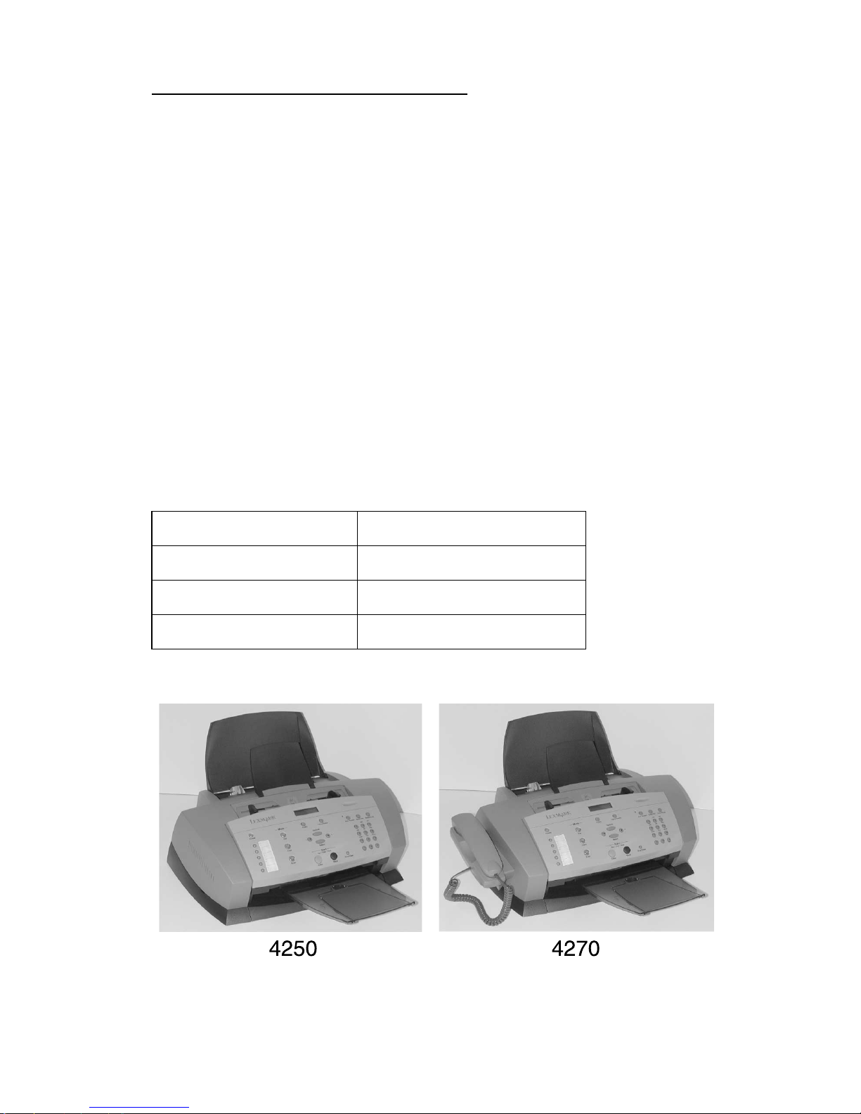
The Le xmark™ 4200 Series All-In-One (4413-XXX) is a letter quality
print, fax, copy, and scan machine. It is a standalone color/mono
copier and fax. The printhead uses small heater plates and nozzles
to control ink flow and the formation of characters on the print media.
The printhead assembly and ink supply are combined into a single
unit. Print cartridges are available as a customer replaceable supply
item. Dual printheads provide color and true black printing without
changing printheads. The number and size of inkjets or nozzles, in
the printhead, determines the overall quality and capability of the
printer. The black cartridge has a total of 208 nozzles and installs on
the right. The color cartridge has a total of 192 nozzles and installs
on the left. The printer is capable of printing in both directions from
either cartridge.
4250 4270
4413-K01 4413-K03
4413-AK1 (DBCS) 4413-AK3 (DBCS)
No handset Handset
General information 1-1
4413-XXX
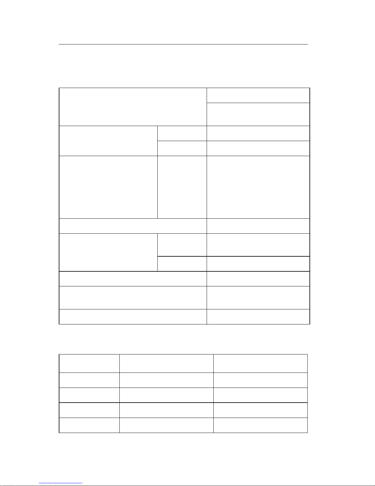
Specifications
Print engine
Technology Thermal Inkjet
2-pin and printhead swapping
type
Speed Color 10 ppm at Draft Mode
Mono 17 ppm at Draft Mode
Resolution Color/Mono Quick Print: 300 x 600 dpi
Normal: 600 x 600 dpi
Better: 1200 x 1200 dpi
Best: 4800 x 1200 dpi for
photo paper
Best: 2400 x 1200 dpi for
other paper
Printing Width 203 mm
Feedin g Method Automati c 100 sheets of 20 lb c ut she ets
(Max 10 mm)
Manual Tray No
Emulation Host Based Printing (GDI)
Printer Driver Windows 98/ME, Win do w s
2000/Windows XP
Interface USB Interface
Printhead
Babbage Mono Standard Birch Color
Printhead 208 nozzles 192 nozzles
Ink Type Pigment Dye
Ink Color Black Color
Ink Yield About 600 sheets About 450 sheets
1-2 Service Manual

4413-XXX
Facsimile
General Scan Method CIS
Scan Width Maximum 216 mm, Minimum 76.2 mm
Feeding Method Sheet Feed
ADF 30 sheets of 20 lb
Guide Document Input Guide
Stacke r Document Output Stack er/Paper
Paper Tray Bin Type (without Manual Tray)
Modem Speed 33.6 Kbps
LCD 2 lines of 16 characters each
Stacker
Scanning Resolution Optical Resolution: 600 dpi (H) x 1200
dpi (V)
Interpolated: 9600 dpi x 9600 dpi
Contrast Darkest/Darken/Normal
Lighten/Lightest
Telephone Speed Dial 79 locations
On-Hook Dial Yes
Last Number Redial Yes
Auto Redial Yes
Ringer Volume S/W Option Setting (4 steps)
Tone/Pulse Select S/W Option Setting
Report and
List
Telephone Number
List
Self Test Yes
Yes
Copy Multipage Copy Up to 99 pages
Grayscale 256 levels
Reduction and
Enlargement
25% - 200%
(Reference is the top center of
document.)
General information 1-3

4413-XXX
Telephone
I/F
Others Sensors Paper Jam
Answering I/F Yes
Extension Phone 1-jack, extension phone transfer
Clock Yes
Scanner
Compatibility TWAIN
Technology Platen CIS
Light Source for Color CIS RGB LEDs (Line Order Control)
Power and size
Power Source 100V-127V with 2-wire power cord fixed
100V-127V with 2-wire separate pow er
cord (Japan)
220V-240V with 2-wire AC inlet separate
power cord
Energy Star Compliant (with 1 watt
regulation)
Dimensions 440.6 X 319.6 X 205.4 mm
Weight (Packed) 15.3 lbs (Packed Weight)
1-4 Service Manual

4413-XXX
Abbreviations
AIO All-In-One
ASF Auto Sheet Feed
B/M Bill of Material
CIS C onta ct Imag e Sensor
EOF End of Form
ESD Electrostatic Discharge
FPC Flat Printhead Cable
FRU Field Replaceable Unit
GDI Graphic Display Interface
HVPS High Voltage Power Supply
LCD Liquid Crystal Display
LVPS Low Voltage Power Supply
OEM Original Equipment Manufacturer
V ac Volts alternating current
V dc Volts direct current
ZIF Zero Insertion Force
General information 1-5

4413-XXX
1-6 Service Manual

4413-XXX
2. Diagnostic information
Start
Power-On Self Test (POST) sequence
1. Lexmark 4200 Series is displayed on the LCD.
2. Power, Fax, Copy, Scan and Auto Answer lights turn on.
3. Copy and Scan button lights turn on.
4. Carrier moves to the left and returns to the maintenance station.
The paper feed motor runs then stops.
5. Enter Fax Number is displayed.
6. Date and Time display when POST is complete.
If your printer completes POST with errors, go to the “Symptom
tables” on page 2-3. Locate the symptom and take the indicated
action.
If your printer does not complete POST, locate the symptom in the
following table and take the indicated action.
Diagnostic information 2-1

4413-XXX
POST symptom table
Symptom Action
LCD or Control
Panel buttons do
not work and no
motors run
Paper feed
gears do not
turn
Carrier does not
move
Carrier slams
side frame
CIS light does
not turn on
Go to the “Power service check” on page 2-14. If okay,
go to the “Control panel problems” on page 2-3.
Go to the “Paper feed service check” on page 2-11.
Go to the “Carrie r transp ort service che c k” on
page 2-6.
Go to the “Carrie r transp ort service che c k” on
page 2-6.
Go to the “CIS assembly service check” on page 2-8.
2-2 Service Manual
4413-XXX
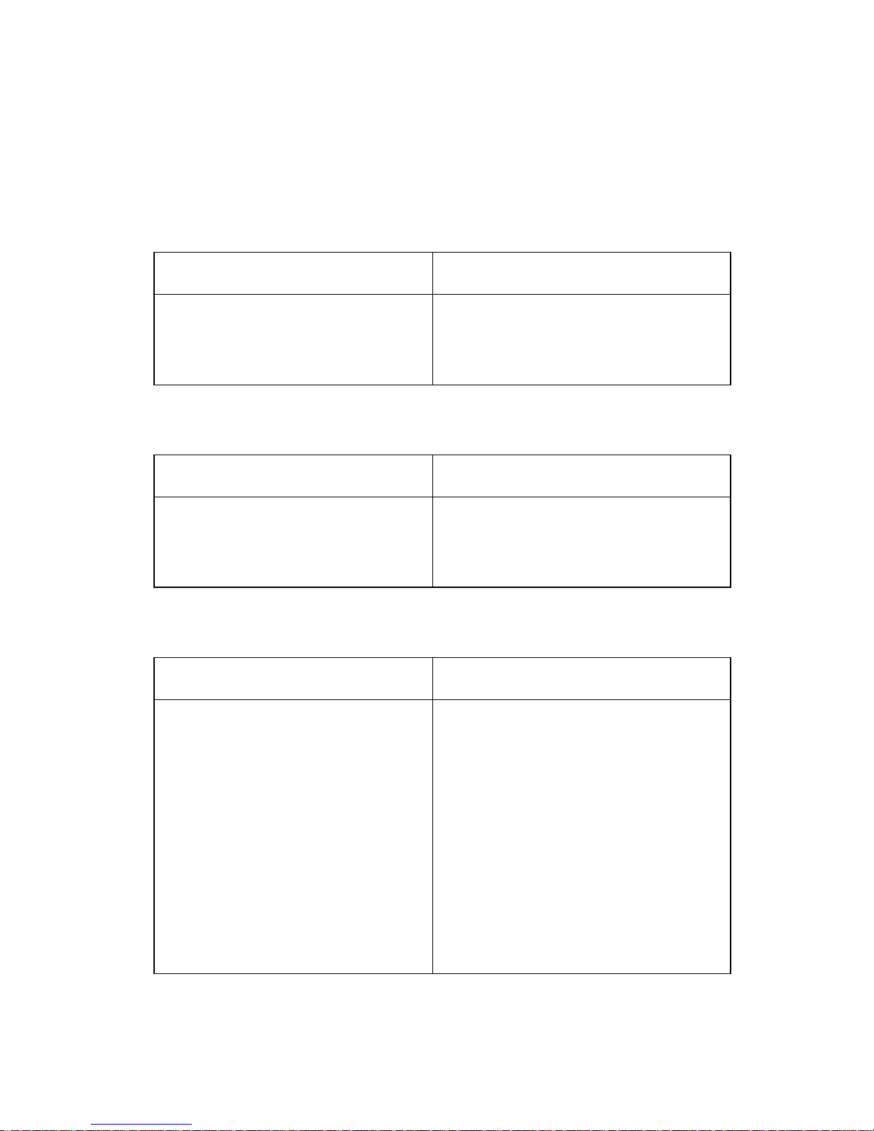
Symptom tables
Locate the symptom in the following tables and take the appropriate
action.
Carrier transport problems
Symptom Action
• No carrier movement
• Slow carrier movement
• Carrier stops
• Carrier slams side frame
Go to the “Carrier transport
service chec k” on page 2-6.
Maintenance station problems
Symptom Action
Maintenance station:
• Fails to cap the printheads
• Fails to clean the printheads
Go to the “Maintenance station
service chec k” on page 2-10.
Control panel problems
Symptom Action
• Buttons do not work
• LCD does not display
Check control panel cable
connection at CN5 on the system
board. Run the “Power-On Self
Test (POST) sequence” on
page 2-1. If the LCD or buttons fail,
check connection CN5. If the
problem remains , r eplace t he contro l
panel assembly. Go to the “Control
panel assembly removal” on
page 4-13.
If the problem still e xists , repla ce the
system board. Go to the “System
board removal” on page 4-19.
Diagnostic information 2-3

4413-XXX
Symptom Action
Document scan sensor does not
detect document
Check con trol p anel cab le conn ector
CN5 on the system b oard. If oka y, go
to the “Scanner motor with gear
assembly service check” on
page 2-9. If the scanner motor is
working correctly, replace the control
panel assembly. Go to the “Control
panel assembly removal” on
page 4-13.
Printer communication problem
Symptom Action
Not able to print Self Test Page Check the USB cable and system
board cable connections. If okay,
replace system board. Go to the
“System board removal” on
page 4-19.
Phone handset/cradle problem
Symptom Action
No dial tone
Handset does not work
Check all phone connections. Be
sure the main phone connection is
connected to the printer.Check pins
5 and 6 for approximately 3 volts on
connector CN11 located on the
system board. If voltage is not
correct, replace the syste m boa rd.
Go to the “Syste m b oard removal”
on page 4-19. If problem still exists,
replace the handset and cradle. Go
to “Handset and cradle removal”
on page 4-24.
2-4 Service Manual

4413-XXX
Scanner problems
Symptom Action
Light does not turn on Go to the “CIS assembly service
check” on page 2-8.
• Scanned images are faded, or
colors are dull, blurry or fuzzy.
Images are slanted or crooked
and the straight lines in the
image appear to be jagged or
uneven.
• Blank copies
• Scanner motor does not run
• Document sensor does not
work
• CIS white roller assembly slips
• Paper does not feed correctly
Go to the “Scan/copy quality
service chec k” on page 2-17.
Go to the “Scanner motor with
gear assembl y servi ce c heck” on
page 2-9.
Go to the “Control panel
problems” on page 2-3.
Go to the “Paper path service
check” on page 2-13.
Paper feed problems
Symptom Action
• Fails to pick paper
• Picks more than one sheet of
paper
• Picks paper but fails to feed
• Paper jams
• Paper fails to exit
• Noisy paper feed
Envelopes fail to feed Go to the “Paper feed service
Paper skews Go to the “Paper path service
Go to the “Paper feed service
check” on page 2-11.
check” on page 2-11.
check” on page 2-13.
Diagnostic information 2-5

4413-XXX
Power problems
Symptom Action
No power in machine, motors do
not operate
Go to the “Power service check”
on page 2-14.
Print quality problems
Symptom Action
• Voids in characters
• Light print
• Prints off the page
• Fuzzy print
• Carrier moves but no print
• Printhead dries prematurely
• Colors print incorrectly
• Vertical alignment off
• Ink smearing
• Vertical streaks on paper
• Print lines crowded
Go to the “Print quality service
check” on page 2-15.
Go to the “Paper feed service
check” on page 2-11.
Service checks
Carrier trans port servi ce check
FRU Action
1 System Board
Carrier Transport
Motor
Check the carrier transport motor connector CN3.
If connected, check for approximately 30 volts on
pins 1 and 3 or at the wire connections located on
the rear of the carrier transport motor. If voltage is
incorrect, replace the system board. If voltage is
correct, check the motor for shorts. If a short is
found, rep lace the mot or . Go to “Carrier transport
motor remov al ” on page 4-24.
2-6 Service Manual

4413-XXX
FRU Action
2 Carrier Transport
Motor
Check the motor for binds, or loose motor pulley.
A noisy or chattering mo tor, or a motor that fails to
turn, can be caused by:
• An open or short in the motor
• An open or short in the motor driver
on the system board
• A bind in the carrier transport
mechanism
With the carrier transport motor cable (CN3)
disconnecte d from the syst em board, che ck for 0
to 16 ohms between the following pins on the
motor:
CN3-2 and CN3-3
If the re adings are incorrect, replace the print
engine. Go to the “Print engine removal” on
page 4-16.
3 Carrier Guide Rod Clean the carrier rod.
Note: Lubricate the rod an d the carrier rod bearing
surfaces with grease P/N 99A0394.
4 Encoder Strip
Carrier Assembly
with Belt
5 Carrier Transport
Belt
Idler Pulley
Assembly
Check the encoder strip for proper installation.
Also , ch eck it for wear, dirt, and grea se. Replace if
needed.
Be sure all printhead connectors are fully seated.
Check the cables for damage.
If the encoder strip and all connections are okay,
but the carrier still slams the side frame, replace
the carrier assembly with belt. Go to the “Carrier
assembly with belt removal” on page 4-18. If
problem rem ains , repl ace the system boa rd. Go to
the “System board removal” on page 4-19.
Check for worn, loose or broken parts. Check for
obstructions blocking carrier movemen t. If pulley
assembly is damaged, replace.
Lubricate carrier to carrier fram e enga gemen t with
grease P/N 99A03 94.
Diagnostic information 2-7
 Loading...