

English
Installation instructions
Fixed/Tilt Plasma/LCD Wall Mount
Model: FT65-03*, FT65B-CC*, ELLCDM07,ELLCDP-07, LM50CDM, DC50CDM,
LM60T, DC60T, LM65FT*, DC65FT*
CAUTION
!
specifically to hold LCD TV’s 34” - 65” and a maximum
weight of up to 200lbs.Using this product with a TV
heavier than the maximum weight may result in injury.
DO NOT RETURN THIS PRODUCT TO THE STORE OR WEB
SITE YOU PURCHASED IT FROM!
IF YOU BELIEVE THIS MOUNT IS DEFECTIVE, HAS
MISSING OR BROKEN PARTS, OR IF YOU ARE HAVING
DIFFICULTY INSTALLING THIS MOUNT TO YOUR WALL
OR FITTING YOUR TV, PLEASE CONTACT OUR COMPANY,
LEVEL MOUNT, DIRECTLY.
Dial 1 888 229 1459 or email us at CustomerSupport@
ElexaUSA.com any time of the day or night for a quick and
efficient solution to your problem.
Our trained Customer Service Department is open 24 hours
a day, 7 days a week, every day of the year and is prepared
to assist you in both English and Spanish.
Please also visit our Web Site at www.LevelMount.com
for assistance.
Features:
• Integrated Bubble Level
• Durable Steel Construction
• Easy 2 Piece Mounting
• Tilts up to 30 degrees
• Locking Lever
• Stud Finder Included
Mounting Equipment Included:
Bag REF Description QTY
1 A Phillips M4 x 12 Bolt 4
B Phillips M4 x 20 Bolt 4
C Phillips M4 x 30 Bolt 4
2 D Phillips M5 x 12 Bolt 4
E Phillips M5 x 20 Bolt 4
F Phillips M5 x 30 Bolt 4
3 G Phillips M6 x 12 Bolt 4
H Phillips M6 x 24 Bolt 4
I Phillips M6 x 35 Bolt 4
4 J Phillips M8 x 25 Bolt 4
K Phillips M8 x 40 Bolt 4
5 L M4/M5 Washer 4
M M4/M5 Spacer 4
5 N M6/M8 Spacer 4
1 O M4 Lock Washer 4
2 P M5 Lock Washer 4
3 Q M6 Lock Washer 4
4 R M8 Lock Washer 4
S 3’’ Hex Screw 6
6 T Hex Washer 6
U Concrete Anchor 6
V M5 x 48 Bolt 8
7* W M5 Hex Nut 8
X M5 Washer 8
Y L-Shape Bar Lock 2
8 Z Phillips screws M5 x 10 Bolt 4
AA M5 Hex Nut 2
BB M5 Butterfly Nut 2
Tools required for attachment to stud:
1/2’’ (12mm) Socket Wrench
Stud finder
Tools required for attaching to concrete:
Electric drill
1/2’’ (12mm) Masonry Bit
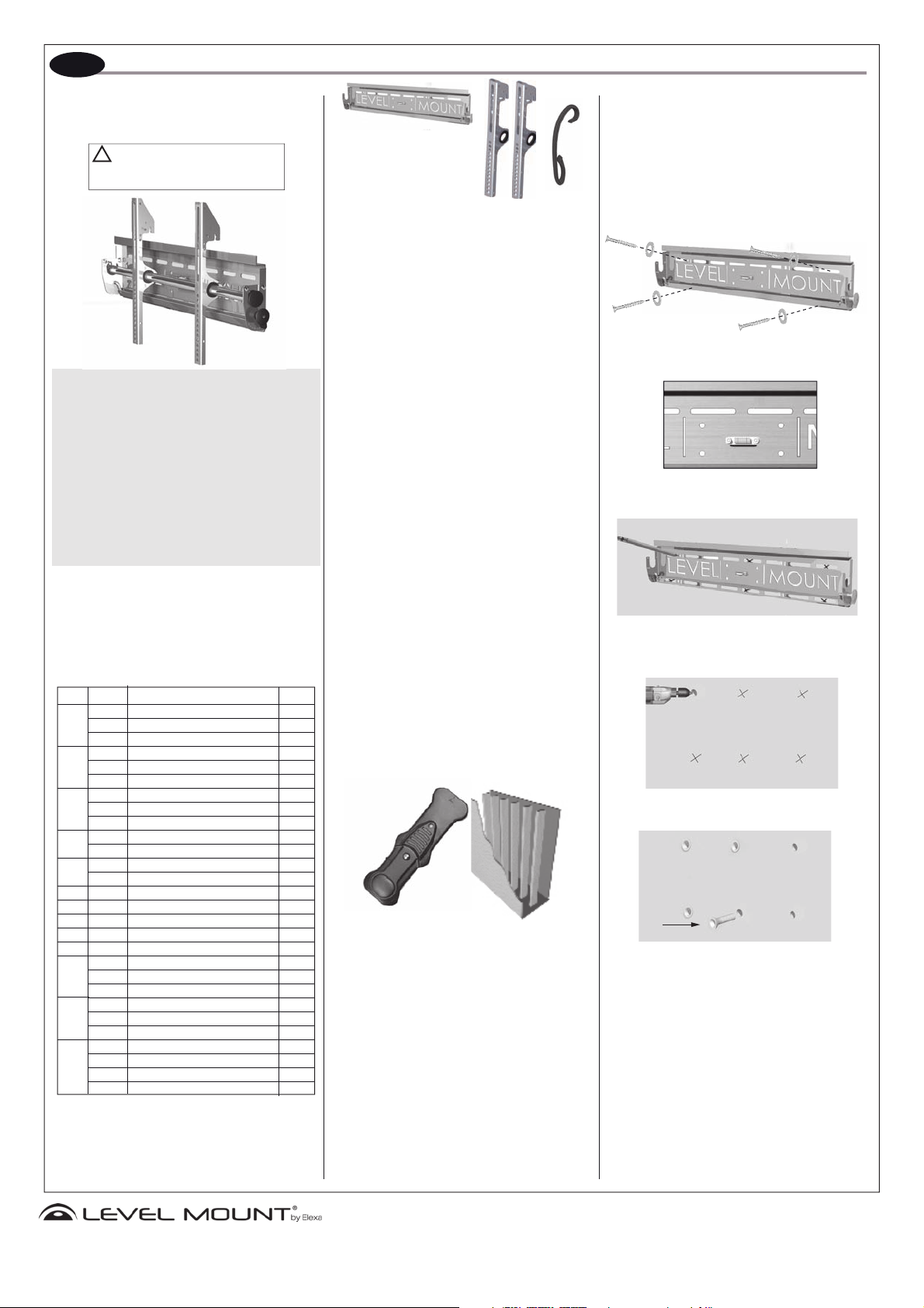
This wall mount was designed
CAUTION:
Installer must make sure the LCD Wall Mount is properly and securely attached and that appropriate fasteners
are used. It is the responsibility of the installer to verify
that the mount is anchored properly to the wall.
PLEASE NOTE: THE MOUNT MUST BE ATTACHED
TO WOOD STUDS OR TO PROPERLY INSTALLED
ANCHORS IN CONCRETE. DO NOT MOUNT ONLY
TO DRYWALL.
Before installing, check to make sure all parts of the
mount are included.
Make sure all screws and bolts are tightened before
allowing Wall Mount to bear the full weight of the
LCD Display.
Attaching Wall Plate to Wooden Studs:
1a. Locate wall studs: Locate a proper place to mount by
Attaching LevelMount to wall: Once the Wall Plate is
Using the Bubble Level as your guide (Figure 3, page
NOTE: Due to the weight of the LCD/Plasma TV’s, it is
necessary to mount the Wall Plate to at least 2 studs.
Attaching Wall Plate to Concrete:
1b. Attaching Wall Mount to concretel: Place the Wall
Insert the anchors into the holes and set them flush to
Once the Wall Plate is in the correct position on the
Wall Plate
Drive the 2nd screw into the opposite upper right hand
Tilt
Arms
Cord
Management
using the included stud finder (Figure 1) It is recommended that the center of the stud be used – and that
a nail be used to verify that a stud has been located.
The mount requires a minimum of two studs to ensure
proper and safe installation. The tilt arms will adjust
horizontally to the right and left up to 8 inches after
you determine the desired viewing location.
in the correct position on the studs, screw 1 Hex Screw
and 1 Hex Washer (P & Q) in the upper left mounting
hole of the Wall Plate into the stud. Do not screw too
tight until after all the screws are in. Drill pilot hole with
1/8 inch drill bit.
2), drive the 2nd screw into the opposite upper right
hand mounting hole of the Wall Plate. Now tighten
both screws, proceed to drive the remaining 2 screws
into the studs as seen in figure 2, page 1.
Figure 1
2. Selecting the Appropriate Hardware for your LCD/
Plasma: CAUTION: Select Bag 1-4, which most resem-
bles the hole side on the back of your LCD/Plasma.
Thread the bolts carefully into your LCD or plasma by
hand to determine which provided mount hardware
Plate at the height you want to install the Plasma/LCD
wall Mount. Mark the six holes you will be using for
concrete anchors (Figure 4). Utilize the built-in bubble
level to ensure proper mounting (Figure 3). Drill holes
(correct diameter) is appropriate for installation. If you
feel resistance, remove the bolt immediately! Next
determine the correct length of the required bolt as
described in the following step.
for the concrete anchors using an electric drill with a
masonry bit (1/2’’ or 12mm (Figure 5). Drill into the wall
at least as deep as the screw is long (3 inches).
*Bag 7 only included with models FT65-03, FT65B-CC,
LM65FT and DC65FT
**PLEASE NOTE: You will not use all of the hardware
the wall by tapping them in with a hammer (Figure 6).
included. Please see last page of the manual if your
Plasma or LCD needs extension arms.
wall, screw 1 Dry Wall Screw and 1 Dry Wall Washer
(P & Q)
in the upper left mounting hole of the
Wall Plate. Do not screw too tight until all the screws
are in.
mounting hole of the Wall Plate, then proceed to drive
the remaining 4 screws into the concrete anchors as
seen in figure 2. Make sure all screws are tightened.
Figure 2
T
S
Figure 3
Figure 4
Figure 5
Figure 6
U
www.LevelMount.com
1-888-229-1459
©2008 Level Mount
Patents Pending
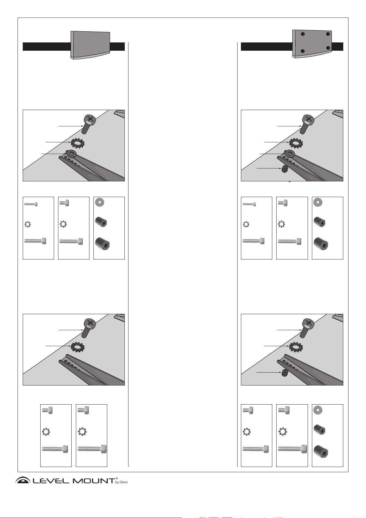
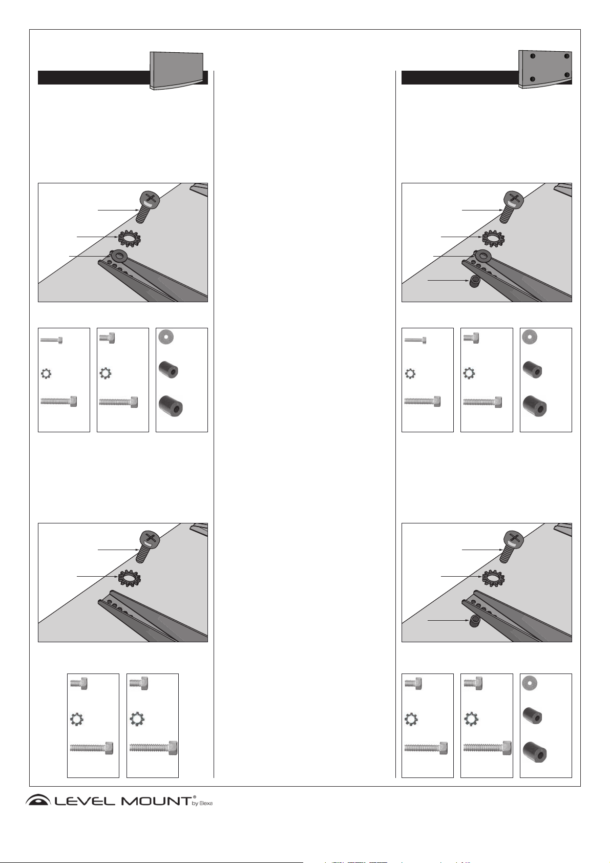
Attaching Monitor Bracket to a LCD/Plasma with:
FLAT BACK
Plasma/LCDs with a flat back panel will require a shorter
bolt. For a flat back Plasma/LCD that required a M4 or
M5 diameter bolt, thread a M4 x 12(A) or a M5 x 12(C)
bolt through the appropriate Lock Washer(L,M), an
M4/M5 Washer, the Tilt Arm and into the TV. Please see
Diagram 1 below for a detailed drawing. Tighten bolts
firmly with a Phillips screwdriver. Do not over tighten.
A or C
L or M
I
Diagram 1
Bag 1
(4x) Phillips
Screws
M4 x 12 Bolt
Bag 2
(4x) Phillips
Screws
M5 x 12 Bolt
Bag 5
(4x) M4/M5
Washer
RECESSED BACK
Plasma/LCDs with a recessed back will require a longer
bolt with a spacer. For a recessed back Plasma/LCD that
required a M4 or M5 diameter bolt, thread a M4x30(B) or a
M5x30(D) bolt through the appropriate Lock Washer(M,N),
an M4/M5 Washer, the Tilt Arm, a M4/M5 Spacer(J) and
into the TV. Please see Diagram 5 below for a detailed
drawing. Tighten bolts firmly with a Phillips screwdriver.
Do not over tighten.
B or D
L or M
I
J
Diagram 5
Bag 1
(4x) Phillips
Screws
M4 x 12 Bolt
Bag 2
(4x) Phillips
Screws
M5 x 12 Bolt
Bag 5
(4x) M4/M5
Washer
(4x) M4 Lock
Washer
(4x) Phillips
Screws
M4 x 30 Bolt
(4x) M5 Lock
Washer
(4x) Phillips
Screws
M5 x 30 Bolt
(4x) M4/M5
Spacer
(4x) M6/M8
Spacer
Plasma/LCDs with a flat back panel will require a shorter
bolt. For a flat back Plasma/LCD that required a M6 or
M8 diameter bolt, thread a M6x12(E) or a M8x16(G) bolt
through the appropriate Lock Washer(N,O), the Tilt Arm
and into the TV. Please see Diagram 2 below for a detailed
drawing. Tighten bolts firmly with a Phillips screwdriver. Do
not over tighten.
E or G
N or O
Diagram 2
Bag 3
Bag 4
(4x) M4 Lock
Washer
(4x) Phillips
Screws
M4 x 30 Bolt
(4x) M5 Lock
Washer
(4x) Phillips
Screws
M5 x 30 Bolt
(4x) M4/M5
Spacer
(4x) M6/M8
Spacer
Plasma/LCDs with a recessed back will require a longer
bolt with a spacer. For a recessed back Plasma/LCD that
required a M6 or M8 diameter bolt, thread a M6x35(F) or a
M8x40(H) bolt through the appropriate Lock Washer(N,O),
the Tilt Arm, a M6/M8 Spacer(J) and into the TV. Please
see Diagram 6 below for a detailed drawing. Tighten bolts
firmly with a Phillips screwdriver. Do not over tighten.
F or H
N or O
J
Diagram 6
Bag 3
Bag 4
Bag 5
(4x) Phillips
Screws
M6 x 12 Bolt
(4x) M6 Lock
Washer
(4x) Phillips
Screws
M6 x 35 Bolt
(4x) Phillips
Screws
M8 x 16 Bolt
(4x) M8 Lock
Washer
(4x) Phillips
Screws
M8 x 40 Bolt
(4x) Phillips
Screws
M6 x 12 Bolt
(4x) M6 Lock
Washer
(4x) Phillips
Screws
M6 x 35 Bolt
(4x) Phillips
Screws
M8 x 16 Bolt
(4x) M8 Lock
Washer
(4x) Phillips
Screws
M8 x 40 Bolt
(4x) M4/M5
Washer
(4x) M4/M5
Spacer
(4x) M6/M8
Spacer
www.LevelMount.com
1-888-229-1459
©2008 Level Mount
Patents Pending
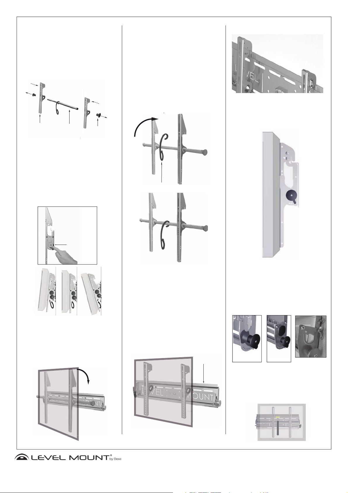
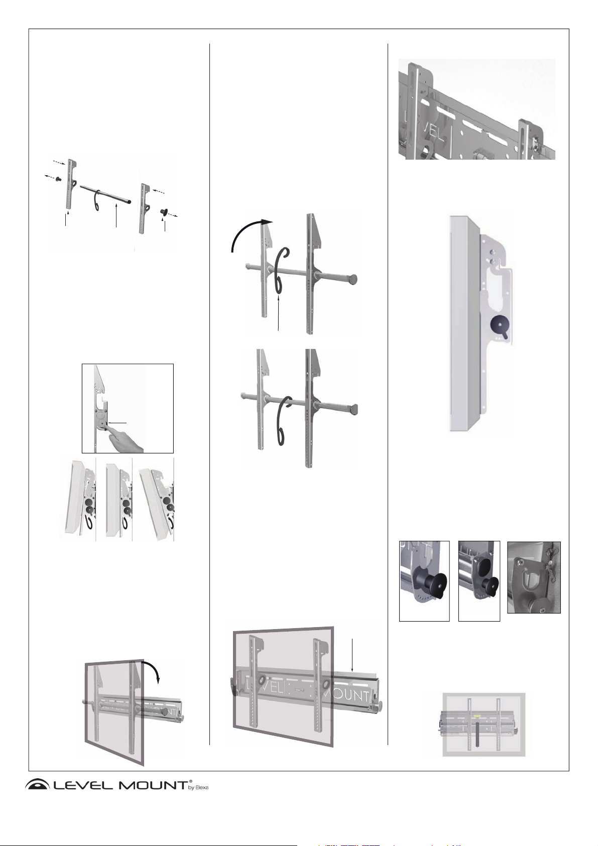
Using as a Tilt Mount:
y
NOTE: NEVER LAY YOUR TELEVISION FACE
DOWN ON ITS GLASS. Laying the television down
on the glass may cause permanent damage.
3. Unscrew the End Caps from both sides and
attach the Tilt Arms by sliding them on (Figure7).
Once the Tilts Arms are slid onto the Horizontal
Adjustment Bar, screw on End Caps.
Tilt Arm
Horizontal
Adjustment Bar
End Cap
Attaching Cord Management:
Attaching Cord Management to Horizontal Bar:
To attach the Cord Management simply hook it
over the Horizontal Adjustment Bar. Then slide
the Cord Management into the best position to
route cords to the wall or an electrical component. It is recommended that you attach the Cord
Management before mounting the display to the
Wall Plate.
It is recommended to attach all wall wires to your
TV prior to mounting the TV on the wall. All cords
and cables should be routed through the Cord
Management hook to keep them out of the way
when lifting the TV. Be careful not to step on any
cords when lifting the TV as you could accidentally
pull the TV from your hands.
Low Profile Design:
The LevelMount Fixed/Tilt Mount is designed in such a
way that it positions the display only 3 inches from the
wall.
Tilting the Display:
Tilting the Display: To tilt the display to a desired
angle, place one hand on the Tilt Adjustment
Knob and one on the bottom of the screen.
Gently unweight the bottom of the display from
the tilt bar by lightly pulling forward. Pull out
on the Tilt Adjustment Knob, adjust display to
desired angle, and release Tilt Adjustment Knob
so that it locks into a designated hole. The display
can be adjusted incrementally by 5 from -15 to
+15 degrees.
-15 0 15
Mounting the Display to the Wall Plate:
4. Attaching Plasma/LCD monitor to wall: Once you
have attached the tilt arms to your display you
are ready to attach the display to the Wall Plate.
It will take 2 people to slide the TV onto the Wall
Plate. Slide the display into the Wall Plate until
the Horizontal Adjustment Bar rests firmly in both
sides of the Wall Plate Hook.
Figure 7
TiltAdjustment
Knob
Cord Management
Using as a Fixed Mount:
Mounting the Display to the Wall Plate:
Attaching Plasma/LCD monitor to wall: Once you
have attached the Tilt Arms to your display you
are ready to attach the display to the Wall Plate.
It will take 2 people to slide the TV onto the Wall
Plate. Slide the attachment hooks of the Tilt Arms
over the top of the upper lip on the Wall Plate
until the Tilt Arms rests firmly on both sides of the
Wall Plate Lip(Figure 8).
Upper Lip
Locking the Display (Using the Tilt Option):
Securely Locking the Display: Once the Horizontal
hex nuts provided to secure the mount in place. A pin
Adjusting the Display:
Adjusting the display horizontally: The Fixed Tilt LCD/
Adjustment Bar is resting on the Wall Plate, it can be
locked down. Lock the display to the Wall Plate by flipping the lock tab over the Horizontal Adjustment Bar to
prevent accidental dislodging. Use the two screws and
can be placed into the lock tab to securely fasten it.
Plasma Mount can be adjusted to fit a VESA 100 (3.94’’
x 3.94’’) mounting pattern and a wider pattern for larger
displays. The display may be adjusted horizontally from
side to side up to 8 inches.
Figure 8
www.LevelMount.com
1-888-229-1459
©2008 Level Mount
Patents Pending
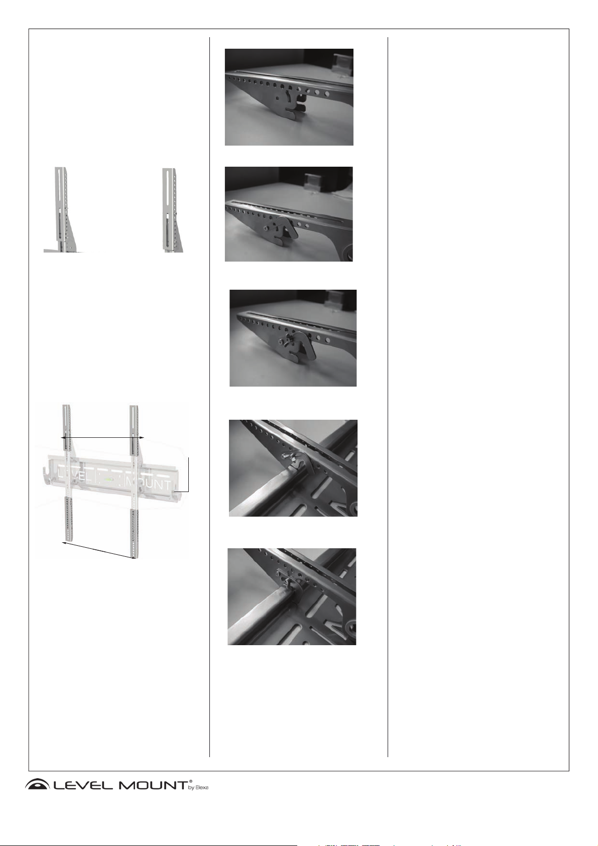
Attaching Extension Arms:
(Note: Some models not included)
4. If you have an oversized LCD/ Plasma TV, you may need
to use the Extension Arms provided. If you need to use
the Extension Arms, you must use all Extensions Arms in
order for the Mount to properly hold your TV.
It is recommended to measure the distance between
the mounting holes on the back of your TV prior to
attaching the Extension Arms. The muliple hole pattern
on the Extension Arms make it easy to adjust to fit your
unique television (Figure 7).
Figure 8
Figure 7
Attach the Extension Arms to the Tilt Arms by threading
the M5 bolts (V) into the provided Lock Washer (W),
through the Extension Arm, through the Tilt Arms and
tighten with the provided Hex Nut (X). 2 M5 bolts must
be used per Extension Arm.
Note: The locking mechanism should face the outside
of the upper left and right Extension Arms. The Locking
Lever may have to be unfastened and reattached when
adjusting the Extension Arms.
Upper Extension
Arms
Locking
Lever
Figure 9
Figure 10
Figure 11
Lower Extension
Arms
Locking the Display (Using the Fixed Option):
To attach the Locking Latch to the Tilt Arm you will need
the hardware from Bag 8. Line up the L-Shape Lock
according to the picture in Figure 9. Place the M5 Bolt
(Z) through L-Shape Lock (Y) and through the Tilt Arm.
Then tighten the bolt using the provided Hex Screw
(AA). You will then need to attach the second M5 bolt
by threading it through the L-Shape Lock (Y), through
the Tilt Arm and tighten with the Butterfly Nut (BB) as
shown in Figure 10. The Butterfly Nut can be loosened
or tightened so that the Tilt Arm can be locked to the
Wall Plate (Figure 11, 12).
Figure 12
www.LevelMount.com
1-888-229-1459
©2008 Level Mount
Patents Pending

Espanol
Installation instructions
Soporte fijo para televisores de plasma/
LCD. Modelos: FT65-03*, FT65B-CC*,
ELLCDM-07,ELLCDP-07, LM50CDM,
DC50CDM, LM60T, DC60T, LM65FT*,
DC65FT*
PRECAUCIÓN:
Al realizar la instalación, asegúrese de que el soporte
de pared para televisores LCD está colocado de forma
correcta y segura, así como de que utiliza los sujetadores adecuados. El instalador es responsable de
comprobar que la base esté sujeta adecuadamente a la
NO DEVUELVA ESTE PRODUCTO A LA TIENDA O SITIO
WEB EN EL QUE LO COMPRÓ.
SI EL SOPORTE ESTÁ DEFECTUOSO, PRESENTA PARTES
ROTAS O LE FALTAN PIEZAS; SI TIENE DIFICULTADES
PARA MONTARLO EN LA PARED O PARA COLOCAR EN ÉL
SU TELEVISOR, PÓNGASE EN CONTACTO DIRECTAMENTE
CON LA EMPRESA LEVEL MOUNT.
Si desea obtener una solución rápida y eficaz para su
problema, llame al número de teléfono 1 888 229 1459 o
envíenos un mensaje de correo electrónico a la dirección
CustomerSupport@ElexaUSA.com, a cualquier hora del día
o de la noche.
Nuestro personal del departamento de atención al cliente
es muy competente, está disponible de manera permanente durante todo el año y le atenderán tanto en inglés
como en español.
Si desea obtener más información, acuda a nuestro sitio
Web www.LevelMount.com
Características
•Nivel de burbuja integrado
•Construcción duradera de acero
•Construcción de 2 piezas, de fácil instalación
•Inclinación de hasta 30°
•Palanca de bloqueo
•Se incluye un detector de montantes
pared y al televisor.
TOME NOTA DE LO SIGUIENTE: LA BASE DEBE ESTAR
FIJA A MONTANTES DE MADERA O A ANCLAJES
PARA MAMPOSTERÍA O CONCRETO QUE ESTÉN
CORRECTAMENTE INSTALADOS. NO SE DEBE FIJAR
DIRECTAMENTE EN EL YESO (DRY WALL).
Antes de comenzar la instalación compruebe que dispone de todas las piezas de la base.
Antes de descargar todo el peso del televisor LCD en el
soporte de pared, asegúrese de que todos los tornillos
y pernos están bien ajustados.
Cómo fijar la placa de pared a los montantes de
1a. Ubicación de los travesaños en la pared: sirviéndose
Travesaño de apoyo
Inserte los anclajes en los agujeros y martíllelos suave-
Cordón de
Brazos de
inclinación
madera:
del detector de travesaños, busque un lugar adecuado
para la colocación del soporte (figura 1). Se recomienda usar la parte central del travesaño y comprobar con
un clavo que se ubicó el mismo. La base debe fijarse al
menos a dos montantes para garantizar una instalación
correcta y segura. Los brazos de inclinación se ajustan
horizontalmente hasta 8 pulgadas hacia la derecha y
la izquierda luego de determinar la posición deseada
para ver el televisor.
enrutamien-
tobles
Tras haber colocado correctamente la placa de apoyo en
Inserte el segundo tornillo en la perforación supe-
de mampostería (figura 4). Utilice el nivel de burbuja
incorporado para garantizar una instalación correcta
(figura 3). Utilice un taladro eléctrico de mano con una
broca para mampostería (1/2’’ o 12 mm (figura 5)) para
hacer los agujeros para los anclajes. Los agujeros en la
pared deben tener una profundidad al menos igual a
la longitud de los tornillos (3 pulgadas).
mente hasta que queden a ras con la pared (figura 6).
la pared, atornille una arandela y un tornillo para paredes tipo drywall (ref. P y Q) en la perforación superior
izquierda de la placa de apoyo. Apriete parcialmente
el tornillo. Lo apretará completamente luego de haber
colocado todos los demás tornillos.
rior derecha de la placa de apoyo y, a continuación,
inserte los cuatro tornillos restantes en los tacos para
cemento, como se indica en la figura 2. Asegúrese de
que todos los tornillos estén bien apretados.
Figura 2
T
S
Figura 3
Figura 4
Accesorios de instalación incluidos:
Kit REF Descripción CANT
1 A Tornillo de estrella M4 x 12 4
B Tornillo de estrella M4 x 30 4
C Tornillo de estrella M4 x 30 4
2 D Tornillo de estrella M5 x 12 4
E Tornillo de estrella M5 x 30 4
F Tornillo de estrella M5 x 30 4
3 G Tornillo de estrella M6 x 12 4
H Tornillo de estrella M6 x 35 4
I Tornillo de estrella M6 x 35 4
4 J Tornillo de estrella M8 x 16 4
K Tornillo de estrella M8 x 40 4
5 L Arandela M4/M5 4
M Espaciador M4/M5 4
5 N Espaciador M6/M8 4
1 O Arandela M4 4
2 P Arandela de seguridad M5 4
3 Q Arandela de seguridad M6 4
4 R Arandela de seguridad M8 4
S Tornillo hexagonal de 3’’ 6
6 T Arandela hexagonal 6
U Taco para cemento 6
V Tornillo M5 x 48 8
7* W Tuerca hexagonal M5 8
X Arandela M5 8
Y Cierre en L 2
8 Z Tornillos de estrella M5 x 10 4
AA Tuerca hexagonal M5 2
BB Tuerca de mariposa M5 2
Herramientas necesarias para la fijación a montantes:
Llave de cubo de 1/2’’ (12 mm)
Detector de travesaños
Herramientas necesarias para la fijación a paredes de
mampostería o concreto:
Taladro eléctrico de mano
Broca de 1/2’’ (12 mm) para mampostería
Colocación del soporte LevelMount en la pared: tras
Tomando el nivel de burbuja como guía (figura 3,
NOTA: Debido al peso de los televisores de LCD y de
plasma, se debe fijar la placa de pared al menos a dos
montantes.
Cómo fijar la placa de pared a superficies de mam-
haber colocado la placa de apoyo en los travesaños,
atornille una arandela y un tornillo hexagonal (ref. P
y Q) en la perforación superior izquierda de la placa
de apoyo hasta que encajen en el travesaño. Espere
hasta haber colocado todos los tornillos para ajustar
firmemente el soporte. Taladre un agujero piloto en el
montante con una broca de 1/8”.
página 2), inserte el segundo tornillo en la perforación
superior derecha de la placa de apoyo. A continuación, ajuste ambos tornillos e inserte los dos tornillos
restantes en los travesaños, como se indica en la figura
2 de la página 1.
2. Elección de las piezas más adecuadas para su televisor
de plasma/LCD: PRECAUCIÓN: seleccione el kit del 1 al
Figura 1
postería o de concreto:1b. Cómo fijar la base de
pared a paredes de bloques de concreto o de ladrillo:
Coloque la placa de pared a la altura a la que desea
instalar la base para televisores de plasma o de LCD.
Marque la posición de los seis agujeros que utilizará
para colocar los anclajes para paredes de concreto o
4 que más se ajuste las perforaciones de la parte posterior de su televisor. Para determinar cuáles tornillos son
los correctos (del diámetro correcto) para la instalación,
atorníllelos suavemente a su televisor de LCD o de plasma.
¡Si detecta resistencia, extraiga el tornillo de inmediato!
Luego debe determinar la longitud correcta de los tornillos, como se describe en el paso siguiente.
*Kit 7 incluidos modelos FT65-03, FT65B-CC, LM65FT
and DC65FT
**TOME NOTA DE LO SIGUIENTE: No va a utilizar todos
los accesorios de instalación incluidos. Si su televisor requiere del uso de los brazos de extensión consulte la última
página del manual.
Figura 5
Figura 6
U
www.LevelMount.com
1-888-229-1459
©2008 Level Mount
Patentes pendientes
Cómo fijar la placa del televisor al televisor de LCD o
de plasma:
PARTE TRASERA PLANA
Los televisores de respaldo plano utilizan pernos más
cortos. En aparatos de plasma/LCD con parte trasera
plana de tornillos de diámetro M4 o M5, enrosque al
televisor un tornillo M4 x 12 (A) o M5 x 12 (C) a través
del brazo de inclinación, la arandela de seguridad correspondiente (L o M) y una arandela M4/M5. Consulte
el diagrama 1 a continuación para ver la instalación en
detalle. Apriete los tornillos firmemente con un destornillador de cruz. Evite apretarlos en exceso.
A or C
L or M
I
Diagrama 1
Kit 1
(4x) Tornillo de
estrella Phillips
M4 x 12
Kit 2
(4x) Tornillo de
estrella Phillips
M5 x 12
Kit 5
(4x) M4/M5
Arandela
PARTE TRASERA CON RANURAS
Los televisores de plasma o LCD cuyo respaldo presenta
una cavidad utilizan pernos más largos y también espaciadores. En aparatos de plasma/LCD con parte trasera con
ranuras para los que se necesiten tornillos de diámetro
M4 o M5, enrosque al televisor un tornillo M4 x 30 (B) o
M5 x 30 (D) a través del brazo de inclinación, la arandela
de seguridad correspondiente (L,M), una arandela M4/M5
y un espaciador M4/M5 (J). Consulte el diagrama 5 a
continuación para ver la instalación en detalle. Apriete los
tornillos firmemente con un destornillador de cruz. Evite
apretarlos en exceso.
B or D
L or M
I
J
Diagrama 5
Kit 1
(4x) Tornillo de
estrella Phillips
M4 x 12
Kit 2
(4x) Tornillo de
estrella Phillips
M5 x 12
Kit 5
(4x) M4/M5
Arandela
(4x) M4 Arandela
de seguridad
(4x) Tornillo de
estrella Phillips
M4 x 30
(4x) M5 Arandela
de seguridad
(4x) Tornillo de
estrella Phillips
M5 x 30
(4x) M4/M5
Espaciador
(4x) M6/M8
Espaciador
Los televisores de respaldo plano utilizan pernos más
cortos. En aparatos de plasma/LCD con parte trasera plana
de tornillos de diámetro M6 o M8, enrosque al televisor
un tornillo M6 x 12 (E) o M8 x 16 (G) a través del brazo de
inclinación y la arandela de seguridad correspondiente
(N,O). Consulte el diagrama 2 a continuación para ver la
instalación en detalle. Apriete los tornillos firmemente con
un destornillador de cruz. Evite apretarlos en exceso.
E or G
N or O
Diagrama 2
Kit 3
Kit 4
(4x) M4 Arandela
de seguridad
(4x) Tornillo de
estrella Phillips
M4 x 30
(4x) M5 Arandela
de seguridad
(4x) Tornillo de
estrella Phillips
M5 x 30
(4x) M4/M5
Espaciador
(4x) M6/M8
Espaciador
Los televisores de plasma o LCD cuyo respaldo presenta
una cavidad utilizan pernos más largos y también espaciadores. En aparatos de plasma/LCD con parte trasera con
ranuras para los que se necesiten tornillos de diámetro M6
o M8, enrosque al televisor un tornillo M6 x 35 (F) o M8
x 40 (H) a través del brazo de inclinación, la arandela de
seguridad correspondiente (N,O) y un espaciador M6/M8
(J). Consulte el diagrama 6 a continuación para ver la instalación en detalle. Apriete los tornillos firmemente con un
destornillador de cruz. Evite apretarlos en exceso.
F or H
N or O
J
Diagrama 6
Kit 3
Kit 4
Kit 5
(4x) Tornillo de
estrella Phillips
M6 x 12
(4x) M6Arandela
de seguridad
(4x) Tornillo de
estrella Phillips
M6 x 35
(4x) Tornillo de
estrella Phillips
M8 x 16
(4x) M8 Arandela
de seguridad
(4x)Tornillo de
estrella Phillips
M8 x 40
(4x) Tornillo de
estrella Phillips
M6 x 12
(4x) M6 Arandela
de seguridad
(4x) Tornillo de
estrella Phillips
M6 x 35
(4x) Tornillo de
estrella Phillips
M8 x 16
(4x) M8 Arandela
de seguridad
(4x) Tornillo de
estrella Phillips
M8 x 40
www.LevelMount.com
(4x) M4/M5
Arandela
(4x) M4/M5
Espaciador
(4x) M6/M8
Espaciador
1-888-229-1459
©2008 Level Mount
Patentes pendientes
Como soporte inclinado:
NOTA: EVITE COLOCAR SU TELEVISOR CON LA
PANTALLA HACIA ABAJO Y APOYADO SOBRE
SU VIDRIO. El colocar el televisor apoyado sobre
su vidrio puede causarle daños permanentes.
3. Desatornille los casquillos de extremo de ambos
lados y coloque los brazos de inclinación (figura
7). Tras haber colocado los brazos de inclinación
en la barra de ajuste horizontal, vuelva a atornillar
los casquillos.
Brazo de
inclinación
Cómo inclinar el televisor:
Cómo inclinar el televisor: para inclinar el televisor
al ángulo deseado coloque una mano sobre la
perilla de ajuste de la inclinación y la otra bajo la
parte inferior de la pantalla. Empuje ésta ligeramente para descargarla de la barra de inclinación.
Levante el regulador de inclinación y vuelva a
introducirlo en la perforación correspondiente
al ángulo de inclinación deseado de forma que
quede bloqueado. Puede ajustar la inclinación de
la pantalla en incrementos de 5, desde -15 a +15
grados.
Barra horizontal
de ajuste
Figura 7
Capacete
Colocación del sistema sujetacables:
4. Colocación del sujetacables en la barra horizontal: para colocar el sujetacables, no tiene más
que engancharlo a la barra de ajuste horizontal.
A continuación, coloque el sujetacables en la
posición que le resulte más conveniente para
colocar los cables junto a la pared o cualquier
aparato eléctrico. Se recomienda colocar el sujetacables antes de montar la pantalla en la placa
de apoyo.
Por otra parte, le recomendamos que coloque
todos los cables de la pared junto al televisor
antes de montarlo en esta. Sitúe todos los cables
en el sujetacables para que no sean un obstáculo
al levantar el televisor y tenga cuidado de no pisar
ningún cable durante este proceso, puesto que le
podría hacer caer el televisor.
El sistema sujetacables
Diseño discreto:
El soporte fijo/inclinado de Level Mount está diseñado
de manera que la pantalla queda a solo 7,6 cm de la
pared.
Botón de ajuste
de la inclinación
-15 0 15
Cómo fijar la placa del televisor a la placa de
pared:
4. Cómo fijar la placa del televisor a la placa de
pared: Luego de fijar los brazos de inclinación a
su televisor ya estará listo para fijar el televisor a
la placa de pared. Se requiere de 2 personas para
fijar el televisor a la placa de pared. Encaje la pantalla en la placa de apoyo de manera que la barra
de ajuste horizontal descanse firmemente sobre
ambos lados del gancho de la placa de apoyo.
Bloqueo de la pantalla (con la opción de inclinación):
Bloqueo seguro de la pantalla: puede bloquear la barra
Como soporte fijo:
Cómo fijar la placa del televisor a la placa de
pared:
5. Colocación del monitor de plasma/LCD en pared:
tras haber colocado los brazos de inclinación en la
pantalla, ya puede instalarla en la placa de apoyo,
Se requiere de 2 personas para fijar el televisor
a la placa de pared. Coloque los ganchos de
encaje de los brazos de inclinación sobre el borde
superior de la placa de apoyo, de manera que
los brazos de inclinación descansen firmemente
en ambos lados del borde de la placa de apoyo
(Figura 8).
Upper Lip
las tuercas hexagonales proporcionadas. Puede ase-
Cómo ajustar la posición del televisor:
Ajuste horizontal del monitor: el soporte para televisores
de ajuste horizontal tras haberla colocado sobre la placa
de apoyo, lo que le permite evitar desplazamientos no
deseados del monitor. Para ello, coloque la lengüeta de
freno en la barra de ajuste horizontal y ajuste el soporte
con los dos tornillos y
gurarlo colocando una pieza pequeña de metal en la
lengüeta de freno.
de plasma/LCD puede ajustarse conforme al estándar
de montaje VESA 100 (3,94’’ x 3,94’’) y otros para
pantallas de mayor tamaño. El soporte le permite un
desplazamiento lateral de hasta 20 cm.
Figura 8
www.LevelMount.com
1-888-229-1459
©2008 Level Mount
Patentes pendientes

Cómo fijar los brazos de extensión:
(Nota: No compatible con todos modelos)
4. Si cuenta con un televisor de plasma/LCD demasiado
grande, es posible que tenga que utilizar los brazos
de extensión proporcionados. Si necesita utilizar los
brazos de extensión, debe utilizarlos todos a efectos
de que la base pueda dar un apoyo adecuado a su
televisor.
Se recomienda que mida la distancia entre los agujeros
roscados de instalación en la parte trasera de su televisor antes de fijar los brazos de extensión. Las diversas
perforaciones de los brazos de extensión permiten un
fácil ajuste del televisor (Figura 7).
Figura 8
Figura 7
Para colocar los brazos de extensión a los brazos de
inclinación enrosque los tornillos M5 (ref. V) en la arandela de seguridad (ref. W), el brazo de extensión y los
brazos de inclinación y, a continuación, ajústelos con la
tuerca hexagonal proporcionada (ref. X). Se debe utilizar dos pernos M5 en cada brazo de extensión.
Nota: El mecanismo de bloqueo debe quedar orien-
tado hacia el exterior de los brazos de extensión superiores derecho e izquierdo. Es posible que al ajustar los
brazos de extensión tenga que quitar y volver a colocar
la palanca de seguridad.
Brazos
de extensión
Palanca de
Seguridad
Figura 9
Figura 10
Figura 11
Brazos de extensión
Bloqueo de la pantalla (con la opción de inclinación):
Para colocar el sujetador de seguridad en el brazo de incli-
nación necesitará las piezas incluidas en el kit 8. Alinee
el cierre en L como se indica en la figura 9. Inserte el
tornillo M5 en el brazo de inclinación a través del cierre
en L (ref. Y) y luego ajústelo con el tornillo hexagonal
proporcionado (ref. AA). A continuación, inserte el
segundo tornillo M5. Para ello, enrósquelo al brazo
de inclinación a través del cierre en L (ref. Y) y ajústelo
con la tuerca de mariposa (ref. BB) como se indica en
la Figura 10. La tuerca de mariposa puede ajustarse de
manera que el brazo de inclinación quede bloqueado
en la placa de apoyo (Figuras 11 y 12).
Figura 12
www.LevelMount.com
1-888-229-1459
©2008 Level Mount
Patents Pending

French
Installation instructions
Support mural fixe/basculant pour téléviseur LCD ou plasma - Modèles : FT6503*, FT65B-CC*, ELLCDM-07,ELLCDP-07,
LM50CDM, DC50CDM, LM60T, DC60T,
LM65FT*, DC65FT*
ATTENTION :
L’installateur doit s’assurer que le support mural pour téléviseur LCD est fixé correctement et que les attaches appropriées sont utilisées. Il incombe à l’installateur de vérifier
que le support de montage est solidement fixé au mur.
REMARQUE : LE SUPPORT DE MONTAGE DOIT ÊTRE
FIXÉ SUR DES MONTANTS DE CLOISON EN BOIS
OU SUR DES POINTS D’ANCRAGE CORRECTEMENT
NE RENVOYEZ PAS CE PRODUIT AU MAGASIN OU SITE WEB OÙ
VOUS L’AVEZ ACHETÉ!
SI VOUS ESTIMEZ QUE CE SUPPORT EST DÉFECTUEUX, QUE
CERTAINES DE SES PIÈCES SONT MANQUANTES OU CASSÉES, OU
SI VOUS AVEZ DU MAL À FIXER LEDIT SUPPORT À VOTRE MUR
OU À INSTALLER VOTRE TÉLÉVISEUR, VEUILLEZ COMMUNIQUER
DIRECTEMENT AVEC NOTRE SOCIÉTÉ, LEVEL MOUNT.
Composez le 1 888 229 1459 ou envoyez-nous un courriel à l’adresse
CustomerSupport@ElexaUSA.com, de jour comme de nuit, afin
d’obtenir une solution rapide et efficace à votre problème.
Notre service à la clientèle est ouvert 24h/24, 7j/7 toute l’année,
et nos employés qualifiés pourront vous répondre en anglais ou
en espagnol.
Nous vous invitons également à visiter notre site Web www.
LevelMount.com si vous avez besoin d’aide.
Caractéristiques :
• Niveau à bulle d’air intégré
• Construction métallique durable
• Support de montage facile en 2 parties
• S’incline jusqu’à 30 degrés
• Levier de blocage
• Détecteur de montant inclus
Équipement de montage fourni :
Sachet REF Description QTÉ
1 A Vis cruciformes M4 x 12 mm 4
B Vis cruciformes M4 x 20 mm 4
C Vis cruciformes M4 x 30 mm 4
2 D Vis cruciformes M5 x 12 mm 4
E Vis cruciformes M5 x 20 mm 4
F Vis cruciformes M5 x 30 mm 4
3 G Vis cruciformes M6 x 12 mm 4
H Vis cruciformes M6 x 24 mm 4
I Vis cruciformes M6 x 35 mm 4
4 J Vis cruciformes M8 x 25 mm 4
K Vis cruciformes M8 x 40 mm 4
5 L Rondelles M4/M5 4
M Entretoises M4/M5 4
5 N Entretoises M6/M8 4
1 O Rondelles frein M4 4
2 P Rondelles frein M5 4
3 Q Rondelles frein M6 4
4 R Rondelles frein M8 4
S Vis à tête hexagonale de 7 cm 6
6 T Rondelles hexagonales 6
U Ancrage pour béton 6
V Vis M5 x 48 mm 8
7* W Écrous hexagonaux M 8
X Rondelle M5 8
Y Équerre de verrouillage 2
8 Z Vis cruciformes M5 x 10 mm 4
AA Écrous hexagonaux M5 2
BB Écrou à oreilles M5 2
Outils nécessaires :
Clé à douille de 12 mm (1/2 po)
Détecteur de montant
Outils nécessaires pour fixer le support sur un mur en
béton :
Perceuse électrique
Foret de maçonnerie de 12 mm (1/2 po)
INSTALLÉS DANS LA MAÇONNERIE OU LE BÉTON. NE
JAMAIS LE FIXER DIRECTEMENT SUR UNE CLOISON
SÈCHE.
Avant l’installation, vérifiez que toutes les pièces du support sont bien présentes.
Vérifiez que tous les boulons et vis sont serrés avant de
laisser reposer le poids total de l’écran LCD sur le support
mural.
Fixation de la plaque murale sur des montants de
cloison en bois :
1a. Localisation des montants de cloison : Localisez un
Fixation du support LevelMount au mur : Une fois
En vous aidant du niveau à bulle d’air (illustration
REMARQUE : Le poids d’un téléviseur LCD ou plasma
exige de fixer la plaque murale à deux montants
minimum.
Fixation de la plaque murale à un mur en béton :1b.
des trous que vous percez dans le mur à la longueur de
la vis (7 cm ou 3 po).
Insérez les ancrages dans les trous en tapant dessus
avec un marteau de manière à ce qu’ils affleurent à la
Plaque murale
surface du mur (Illustration 6).
Une fois que la plaque murale est correctement posi-
tionnée sur le mur, vissez une vis autoforeuse et une
rondelle pour vis autoforeuses (P et Q) dans le trou de
montage supérieur gauche de celle-ci. Ne serrez pas à
Bras d’in-
clinaison
Système
de gestion
des câbles
fond avant d’avoir inséré toutes les vis.
Fixez la deuxième vis dans le trou de montage
supérieur droit opposé de la plaque murale, puis les 4
vis restantes aux ancrages pour béton comme indiqué
dans l’illustration 2. Assurez-vous de bien serrer toutes
les vis.
montant à l’aide du détecteur fourni (illustration 1). Il
est recommandé d’utiliser le centre du montant et de
planter un clou pour vérifier qu’il y a bien un montant
à l’endroit choisi. Le support doit se fixer sur deux
montants minimum pour que l’installation soit sûre.
Une fois que vous avez choisi l’emplacement de votre
écran, vous pouvez régler horizontalement les bras
basculants, jusqu’à 20 cm (8 po) vers la droite et vers
la gauche.
que la plaque murale est correctement positionnée
sur les montants de cloison, vissez une vis et une
rondelle hexagonales (P et Q) dans le trou de montage supérieur gauche de celle-ci. Ne serrez pas à
fond avant d’avoir inséré toutes les vis. Percez le trou
d’implantation à l’aide d’un foret de 3.2 mm (1/8 po).
3, page 2), placez la deuxième vis dans le trou de
montage supérieur droit opposé de la plaque murale
et vissez-la. Serrez les deux vis, puis vissez les 2 vis restantes aux montants, comme indiqué dans l’illustration
2, page 2.
Illustration 1
2. Choix du matériel approprié pour votre téléviseur
LCD ou plasma : ATTENTION : Parmi les sachets 1 à
4, choisissez celui qui correspond le mieux à la taille du
trou situé au dos de votre téléviseur LCD ou plasma.
À la main, vissez délicatement les vis dans votre écran
LCD ou plasma pour identifier, parmi le matériel fourni,
la plus adaptée à votre installation (diamètre approprié).
1b. Fixation du support mural à un mur en blocs de
béton ou en briques : Placez la plaque murale à la
hauteur à laquelle vous souhaitez installer le support
mural pour téléviseur LCD ou plasma. Marquez les six
trous que vous voulez utiliser pour les ancrages pour
béton (Illustration 4). Aidez-vous du niveau à bulle d’air
intégré pour réaliser un montage parfait (Illustration 3).
Percez les trous pour les ancrages pour béton à l’aide
d’une perceuse électrique et d’un foret de maçonnerie
12 mm ou 1/2 po (illustration 5). Adaptez la profondeur
Si vous constatez une résistance, retirez la vis immédiatement! Déterminez ensuite la longueur appropriée de
la vis, tel que décrit dans l’étape suivante.
*Sachet 7 fourni modèles FT65-03, FT65B-CC, LM65FT
and DC65FT
**REMARQUE IMPORTANTE : Vous ne devez pas
utiliser tout le matériel fourni. Si votre téléviseur LCD
ou plasma nécessite des plaques d’extension, reportezvous à la dernière page de ce manuel.
T
S
Illustration 2
Illustration 3
Illustration 4
Illustration 5
U
Illustration 6
www.LevelMount.com
Tél. : 1-888-229-1459
©2008 Level Mount
Brevets en attente

Fixation du support d’écran au téléviseur LCD ou
plasma:
PANNEAU ARRIERE PLAT
Un téléviseur plasma ou LCD avec un panneau arrière
plat nécessite une vis plus courte. Si le panneau arrière
plat de votre téléviseur plasma ou LCD nécessite une vis
de diamètre M4 ou M5, enfilez une vis M4 x 12 mm (A)
ou M5 x 12 mm (C) à travers la rondelle frein correspondante (L, M), une rondelle M4/M5, le bras basculant et
le téléviseur, comme indiqué dans le schéma 1. Serrez
les vis à l’aide d’un tournevis cruciforme. Ne les serrez
pas excessivement.
A or C
L or M
I
Schéma 1
Sachet 1
(4x) Vis cruciformes
M4 x 12
Sachet 2
(4x) Vis cruciformes M5 x 12
Sachet 5
(4x) M4/M5
Rondelles
PANNEAU ARRIERE EN RETRAIT
Un téléviseur plasma ou LCD avec un panneau arrière en
retrait nécessite une vis plus longue et une entretoise. Si
le panneau arrière en retrait de votre téléviseur plasma
ou LCD nécessite une vis de diamètre M4 ou M5, enfilez
une vis M4 x 30 mm (B) ou M5 x 30 mm (D) à travers
la rondelle frein correspondante (M, N), une rondelle
M4/M5, le bras basculant, une entretoise M4/M5 (J) et le
téléviseur, comme indiqué dans le schéma 5. Serrez les
vis à l’aide d’un tournevis cruciforme. Ne les serrez pas
excessivement.
B or D
L or M
I
J
Schéma 5
Sachet 1
(4x) Vis cruciformes M4 x 12
Sachet 2
(4x) Vis cruciformes M5 x 12
Sachet 5
(4x) M4/M5
Rondelles
(4x) M4
LRondelles frein
(4x) Vis cruciformes
M4 x 30
(4x) M5
Rondelles frein
(4x) Vis cruciformes M5 x 30
(4x) M4/M5
Entretoises
(4x) M6/M8
Entretoises
Un téléviseur plasma ou LCD avec un panneau arrière plat
nécessite une vis plus courte. Si le panneau arrière plat
de votre téléviseur plasma ou LCD nécessite une vis de
diamètre M6 ou M8, enfilez une vis M6 x 12 mm (E) ou
M8 x 16 mm (G) à travers la rondelle frein correspondante
(N, O), le bras basculant et le téléviseur, comme indiqué
dans le schéma 2. Serrez les vis à l’aide d’un tournevis
cruciforme. Ne les serrez pas excessivement.
E or G
N or O
Schéma 2
Sachet 3
Sachet 4
(4x) M4
Rondelles frein
(4x) Vis cruciformes
M4 x 30
(4x) M5
Rondelles frein
(4x) Vis cruciformes
M5 x 30
(4x) M4/M5
Entretoises
(4x) M6/M8
Entretoises
Un téléviseur plasma ou LCD avec un panneau arrière en
retrait nécessite une vis plus longue et une entretoise. Si
le panneau arrière en retrait de votre téléviseur plasma
ou LCD nécessite une vis de diamètre M6 ou M8, enfilez
une vis M6 x 35 mm (F) ou M8 x 40 mm (H) à travers la
rondelle frein correspondante (N, O), le bras basculant,
une entretoise M6/M8 (J) et le téléviseur, comme indiqué
dans le schéma 6. Serrez les vis à l’aide d’un tournevis
cruciforme. Ne les serrez pas excessivement.
F or H
N or O
J
Schéma 6
Sachet 3
Sachet 4
Sachet 5
(4x) Vis cruciformes M6 x 12
(4x) M6
Rondelles frein
(4x) Vis cruciformes
M6 x 35
(4x) Vis cruciformes
M8 x 16
(4x) M8
Rondelles frein
(4x) Vis cruciformes
M8 x 40
(4x) Vis cruciformes M6 x 12
(4x) M6
Rondelles frein
(4x) Vis cruciformes
M6 x 35
(4x) Vis cruciformes M8 x 16
(4x) M8
Rondelles frein
(4x) Vis cruciformes
M8 x 40 Bolt
(4x) M4/M5
Rondelles
(4x) M4/M5
Entretoises
(4x) M6/M8
Entretoises
www.LevelMount.com
Tél. : 1-888-229-1459
©2008 Level Mount
Brevets en attente

Utilisation du support basculant :
REMARQUE : NE POSEZ JAMAIS VOTRE
TÉLÉVISEUR FACE CONTRE LE SOL. Cela peut
entraîner des dommages irréversibles.
3. Retirez les bouchons situés sur les côtés des bras
basculants et faites glisser ces derniers dans
la barre de réglage horizontale (illustration 7).
Revissez ensuite les bouchons.
Bras d’in-
Inclinaison de l’écran :
Inclinaison de l’écran : Pour orienter l’écran dans
la position désirée, placez une main sur l’un des
boutons de réglage de l’inclinaison et l’autre
sous la partie inférieure de l’écran. Éloignez
délicatement l’écran de la barre d’inclinaison en
le tirant vers vous. Tirez sur le bouton de réglage
de l’inclinaison, orientez l’écran jusqu’à atteindre
l’angle souhaité, puis relâchez le bouton pour
lui permettre de se loger dans le trou désigné.
L’écran peut se régler par incréments de 5 degrés,
de -15 à +15 degrés.
clinaison
Barre de réglage
horizontal
Illustration 7
Bouchon d’ex-
trémité
Fixation du système de gestion de câble :
4. Fixation du système de gestion de câble sur la
barre horizontale : Pour fixer le système, accrochez-le tout simplement à la barre de réglage
horizontale. Placez-le ensuite à l’emplacement
le plus approprié pour orienter les câbles le
long du mur ou vers un composant électrique.
Il est recommandé d’accrocher le système de
gestion de câble avant de fixer l’écran à la
plaque murale.
Il est recommandé de brancher tous les câbles
muraux à votre téléviseur avant de fixer celui-ci
au mur. Tous les câbles doivent être placés dans
le crochet du système de gestion de câble afin
de faciliter l’installation du téléviseur. Assurezvous que vous ne marchez pas sur l’un des câbles
lorsque vous soulevez le téléviseur car il risque
de vous glisser des mains.
Système de gestion de câbles
Architecture discrète:
L’architecture du support fixe/basculant LevelMount
permet d’installer le téléviseur à 6.2 cm (3 po) du mur
seulement.
Molette
de réglage
de l’inclinaison
-15 0 15
Installation de l’écran sur la plaque murale :
4. Fixation du téléviseur plasma ou LCD au mur :
Une fois que vous avez fixé les bras basculants à
votre écran, il ne vous reste plus qu’à le fixer sur
la plaque murale. Deux personnes sont nécessaires pour faire glisser le téléviseur dans la plaque
murale. Faites glisser l’écran sur la plaque murale
jusqu’à ce que la barre de réglage horizontale
repose fermement sur les crochets sur la plaque
murale.
Verrouillage de l’écran (en utilisant l’option d’inclinaison) :
Verrouillage sûr de l’écran : Une fois que vous avez logé
Utilisation du support fixe :
écrous hexagonaux fournis pour fixer l’attache de
Installation de l’écran sur la plaque murale:
5. Fixation du téléviseur plasma ou LCD au mur :
Une fois que vous avez fixé les bras basculants à
votre écran, il ne vous reste plus qu’à le fixer sur
la plaque murale. Deux personnes sont nécessaires pour faire glisser le téléviseur sur la plaque
murale. Faites glisser les crochets de fixation des
bras basculants sur la languette supérieure de
la plaque murale jusqu’à ce que les bras reposent fermement de chaque côté de la languette
(Illustration 8).
Réglage de l’écran :
Réglage horizontal de l’écran : Le modèle de support
la barre de réglage horizontale dans la plaque murale,
vous pouvez la verrouiller. Pour éviter que le téléviseur
ne soit délogé accidentellement, fixez l’écran à la plaque murale en tournant l’attache de verrouillage vers la
barre de réglage horizontale. Utilisez les deux vis et les
verrouillage. Vous pouvez insérer une cheville dans
l’attache pour la verrouiller.
mural fixe/basculant pour téléviseur LCD/Plasma se
règle de façon à être compatible avec les modèles de
montage VESA 100 mm (3,94 x 3,94 po) et les modèles
de montage plus larges pour les écrans de grande
taille. L’écran peut se régler horizontalement jusqu’à 20
cm (8 po).
Illustration 8
www.LevelMount.com
Tél. : 1-888-229-1459
©2008 Level Mount
Brevets en attente

Fixation des bras d’extension :
(Remarque : Non inclus pour certains modèles)
4. Si vous disposez d’un téléviseur LCD ou plasma de
grande taille, vous devez utiliser les bras d’extension
fournis. Si la taille de votre téléviseur exige l’installation de bras d’extension, vous devez utiliser toutes les
extensions fournies afin d’assurer le soutien complet du
téléviseur par le support.
Avant de fixer les bras d’extension, nous vous recom-
mandons de mesurer la distance entre les trous de
montage situés à l’arrière de votre téléviseur. Les bras
d’extension sont équipés de nombreux trous afin de
faciliter le réglage de tous les modèles de téléviseur
(Illustration 7).
Illustration 8
Illustration
7
Fixez les bras d’extension aux bras basculants en y insé-
rant les vis M5 (V) et les rondelles frein (W), puis serrez à
l’aide des écrous hexagonaux (X). Utilisez 2 vis M5 pour
chaque bras d’extension.
Remarque : Le mécanisme de blocage doit être orienté
vers l’extérieur des parties supérieures droite et gauche des bras d’extension. Lors du réglage des bras
d’extension, le levier de blocage doit être desserré
puis resserré.
Bras d’extension
Levier de
Blocage
Illustration 9
Illustration 10
Illustration 11
Bras d’extension
Verrouillage de l’écran (en utilisant l’option fixe) :
Pour fixer l’équerre de verrouillage au bras basculant,
vous devez utiliser le matériel contenu dans le sachet
8. Alignez l’équerre de verrouillage comme indiqué
dans l’illustration 9. Insérez la vis M5 à travers l’équerre
de verrouillage (Y) et le bras basculant. Serrez-le à
l’aide de l’écrou hexagonal fourni (AA). Vous devez
à présent visser la deuxième vis M5 à travers l’équerre
de verrouillage (Y) et le bras basculant, puis serrez à
l’aide d’un écrou à oreilles BB) comme indiqué dans
l’illustration 10. L’écrou à oreilles peut se desserrer et
se resserrer pour verrouiller le bras basculant à la plaque
murale (illustrations 11 et 12).
Illustration 12
www.LevelMount.com
Tél. : 1-888-229-1459
©2008 Level Mount
Brevets en attente
 Loading...