

Page 1

LCD MONITOR MOUNT
Installation Instructions
Articulating Universal Desktop Mount Fits 10”- 30” (25.4 cm - 76.2
cm) Flat Panel Displays - up to 35 lb (16 kg) capacity - Black
Support articulé pour moniteur et TV jusqu’à 76.2 cm (30 pouces)
Please read these Installation Instructions entirely, including the
Warnings, before you start the installation and assembly of the
Desktop Mount.
Veuillez lire intégralement la présente notice de montage, y compris les Avertissements, avant de commencer l’installation et le
montage du support.
Page 2
g
Need Help?
Helpful Hints
If you have installation questions about your TV Wall Mount, please go to www.levelmount.com to view
product tutorials.
Contacting Level Mount Customer Service
If you have questions, our trained Customer Service Department is happy to assist you 24 hours a day,
7 days a week, every day of the year. Contact Level Mount Customer Service as follows:
• In the United States dial: 1-888-229-1459
• In Europe dial: +0044 844 567 2657
• In the United Kingdom dial: 0844 567 2657
• E-mail Level Mount at [email protected]
DO NOT RETURN THIS PRODUCT TO THE STORE OR WEB SITE FROM WHICH IT WAS
PURCHASED
If you believe the product is defective, has a missing or broken part or are having diffi culty with
assembly, please contact Level Mount directly 24 hours a day, 7 days a week, 365 days a year as listed
above, for a quick and effi cient solution to your problem.
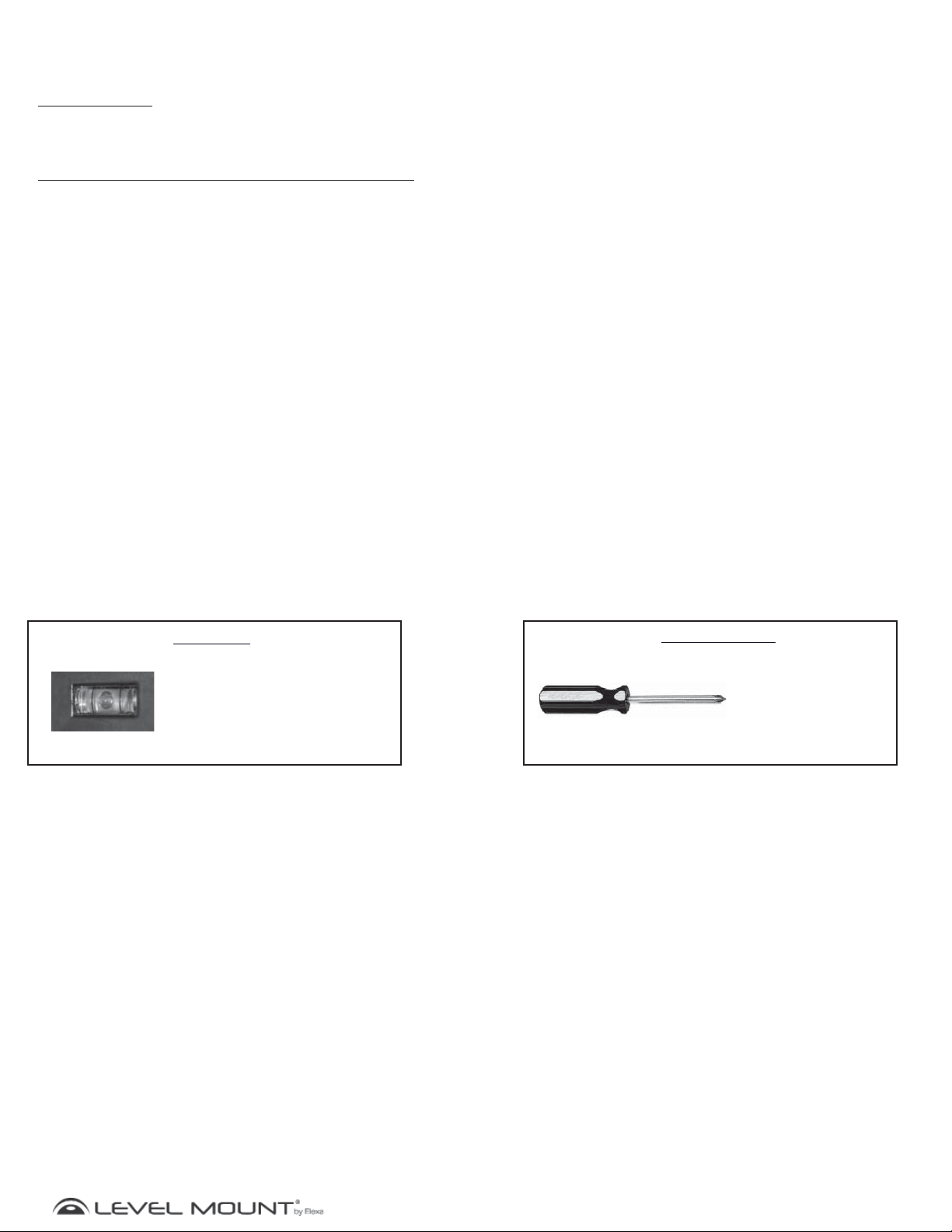
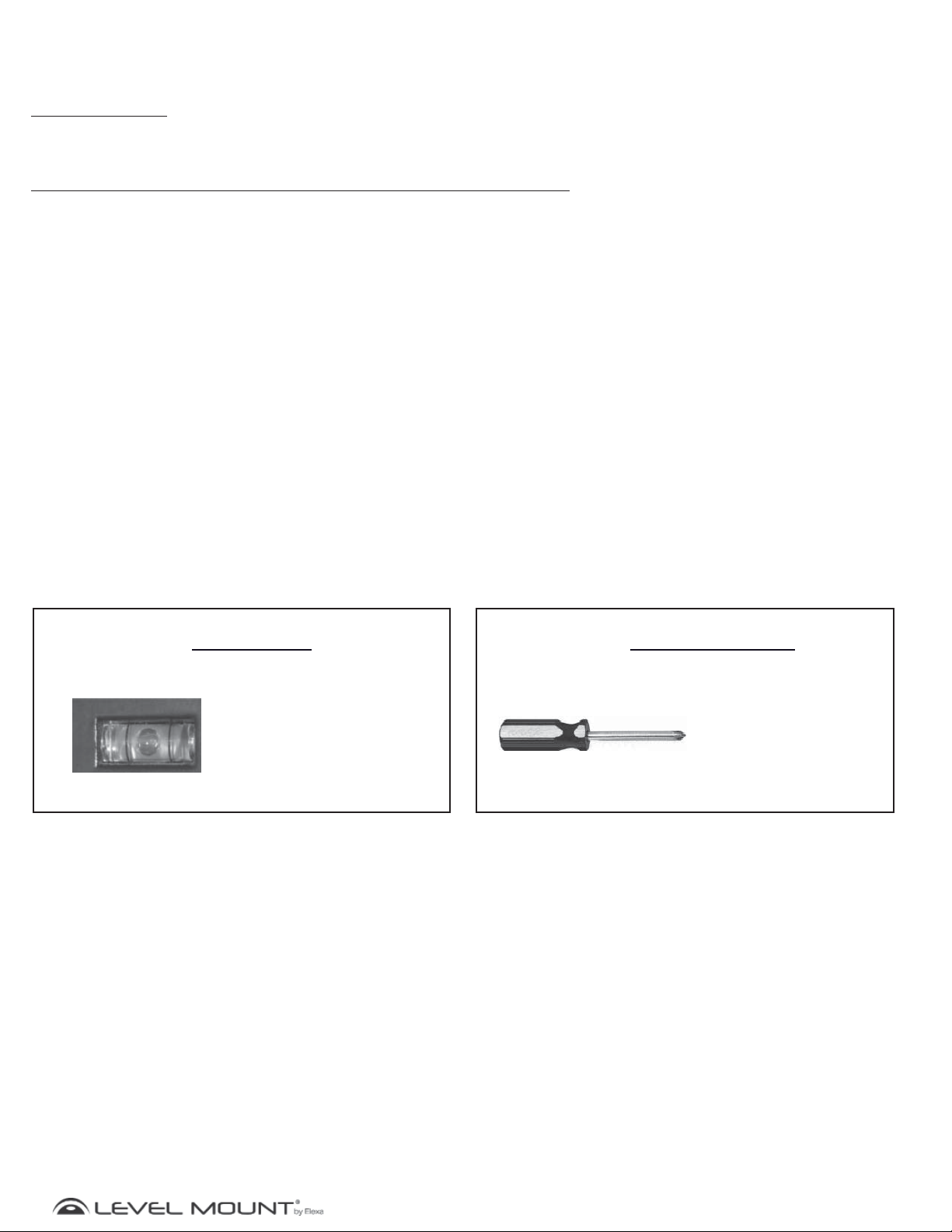
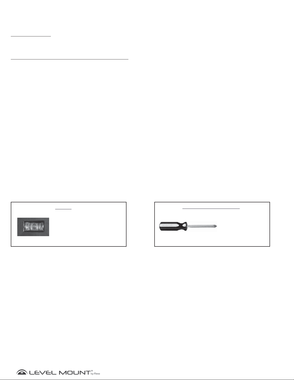
Tools Required
Included
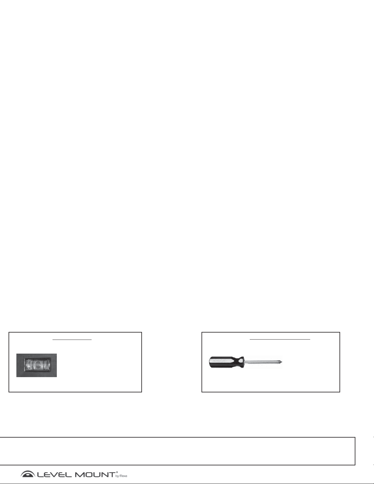
Built-in Bubble Level/
Spirit Level
Not Included
Phillips
Screwdriver
www.levelmount.com
2
©2011 Level Mount - Patents Pendin
1-888-229-1459
EU: +0044 844 567 2657
UK: 0844 567 2657
Page 3
g
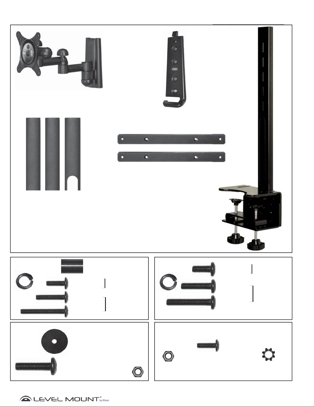
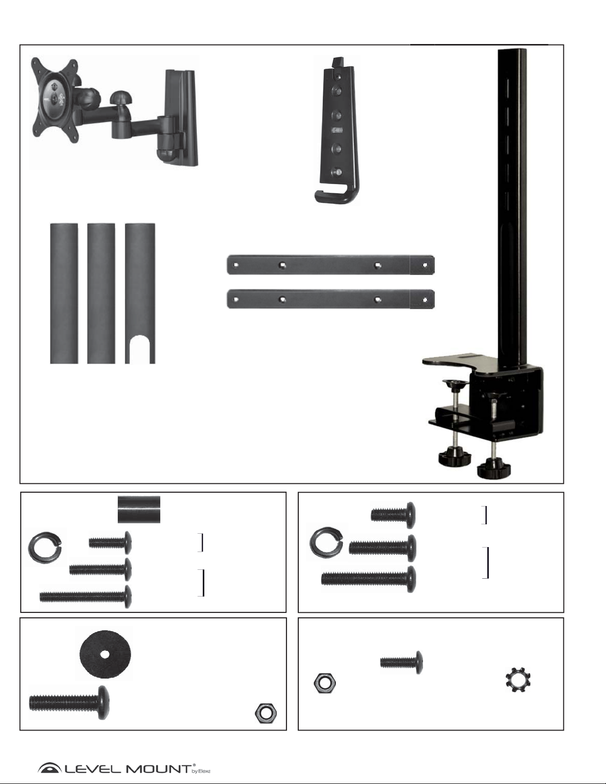
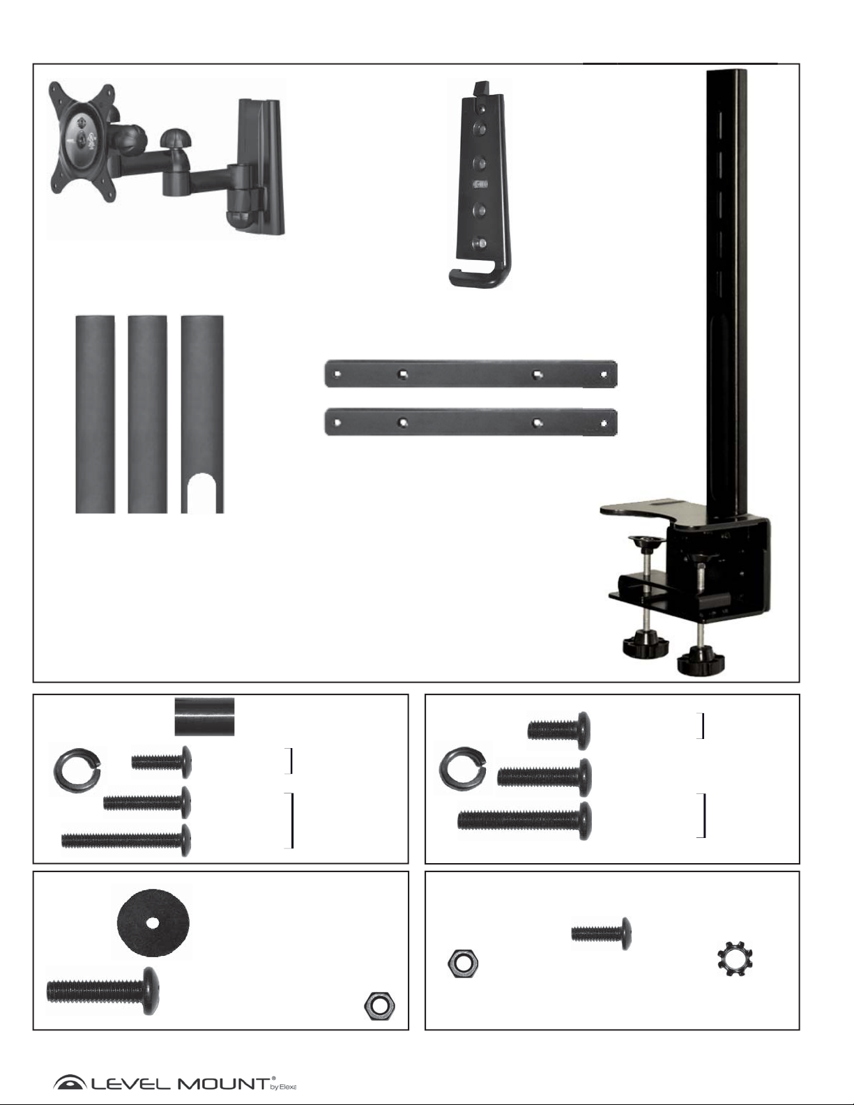
What’s in the box?
()
Flat Panel Bracket
(DSK30DJ Pictured)
Arm Plate
Cord Cover
(Comes pre-attached to back
of Desk Top Arm)
Bag 1
(4) M4 Washer
(4) Spacer
15.9mm
(4) M4 x12mm
Phillips Bolt
(4) M4 x 20mm
Phillips Bolt
(4) M4 x 30mm
Phillips Bolt
Flat Back
Hardware
Recessed
Back
Hardware
Adapter Arms
Desk Top Arm
Bag 2
(4)M5 Washer
(4) M5 x 12mm
Phillips Bolt
(4) M5 x 20mm
Phillips bolt
(4) M5 x 30mm
Phillips Bolt
Flat Back
Hardware
Recessed
Back
Hardware
Bag 3
(2) Washer
16mm x 6.3mm x 1.2mm
(2) Phillips Bolt
M6 x 22mm
(2) M6 Hex Nut
Bag 4
(4) M4 Hex Nut
3
Phillips Bolt Adapter Kit
(4) Philips Bolt
M4 x 12mm
(4) M4 Lock Washer
©2011 Level Mount - Patents Pendin
www.levelmount.com
1-888-229-1459
EU: +0044 844 567 2657
UK: 0844 567 2657
Page 4
g
Getting Started
!
CAUTION!
This Desktop Mount was designed specifically to hold 10” – 30” (25.4cm – 76.2cm) Flat Panel
Monitors and a maximum weight of up to 35 lbs (16kg). Using this product with a Flat Panel Monitor
heavier than the maximum weight, or that exceeds these dimensions, may result in serious personal
injury and damage to equipment and property.
1. Do not begin the installation of the Desktop Mount until you have read and understood the instructions and
warnings contained in these Installation Instructions. Failure to read, thoroughly understand and follow the
instructions can result in serious personal injury and damage to equipment and property. It is the installer’s
responsibility to make sure all components are properly assembled and installed using the instructions provided.
2. If you have questions that do not appear to be covered in these Installation Instructions, please contact us as
described under the “Need Help” section above. If you are at all unsure about any step in these instructions or
your ability to install the Desktop Mount safely and securely, you should seek professional help from a qualified
contractor.
3. This Desktop Mount contains small items that could be a hazard if swallowed. Keep these items away from
children.
4. Under no circumstances may the Desktop Mount be used outdoors. Use of this product outdoors could lead to
product failure and may result in serious personal injury, or damage to equipment and property.
5. The Desktop Mount must be attached to a desk top only as specified in these Installation Instructions. Do not use
the Desktop Mount for devices other than as specified in these instructions.
6. Make sure all screws and bolts are tightened before allowing the Desktop Mount to bear the full weight of the Flat
Panel Monitor. Tighten screws and bolts firmly but do not over-tighten them. Once the screw is flush against the
Flat Panel Monitor and the screwdriver is more difficult to turn and will not turn farther, stop; otherwise there is
a risk of over-tightening the bolt. Over-tightening the screws or bolts could damage the Desktop Mount, greatly
reducing its holding power. Periodic tightening may be required.
7. Screws should easily and completely thread into the Flat Panel Monitor mounting holes. If any of the screws
provided are not suitable for the Desktop Mount system, the installer must not under any circumstances drill holes
into the Flat Panel Monitor or into the Desktop Mount components. Using screws of improper size can damage
the Flat Panel Monitor.
8. Do not lift more weight than you can handle. If necessary, use at least two people when lifting and positioning the
Flat Panel Monitor on the Desktop Mount.
9. Before installing, check to make sure all parts of the Desktop Mount indicated in these Installation Instructions
are included and undamaged. Never use damaged parts or try to install the Desktop Mount if you do not have all
needed parts.
10. It is the installer’s responsibility to select the appropriate installation location and the supporting surface on which
to mount this Desktop Mount and to ensure that the Desktop Mount is anchored properly to the Desktop. It is also
the installer’s responsibility to ensure that the Flat Panel Monitor is properly and securely attached to the Desktop
Mount using only the enclosed fasteners and components and to verify that the screws and power cords do not
touch wires, pipes, or metal parts (since this could cause damage to these items or cause electrical shock).
11. Level Mount.has made every effort to make these Installation Instructions accurate and complete. However,
Level Mount makes no claim that the information contained herein covers all details, conditions or variations, nor
does it provide for every possible contingency in connection with the installation, assembly or use of this product.
Level Mount makes no representation or warranty, express or implied, regarding the accuracy, completeness or
sufficiency of the information contained in this document. Level Mount is not responsible for any damage or injury
caused by incorrect mounting, assembly, installation or use.
www.levelmount.com
4
©2011 Level Mount - Patents Pendin
1-888-229-1459
EU: +0044 844 567 2657
UK: 0844 567 2657
Page 5
g
Assembly/Installation
H
s
Flat Back
Monitor
Flat Panel
Monitor Bracket
Adapter Arm
M4 Bolt
Phillips
Screwdriver
Flat Panel
Monitor
Figure 1
Figure 2
Figure 3
Recessed Back
Monitor
M4 Lock Washer
M4 Hex NutM4
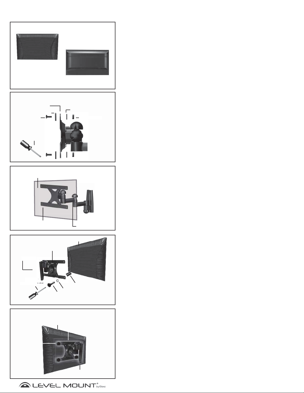
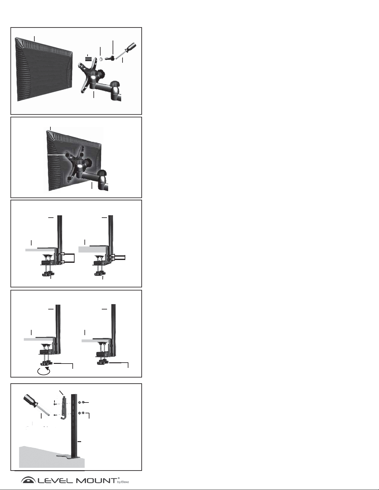
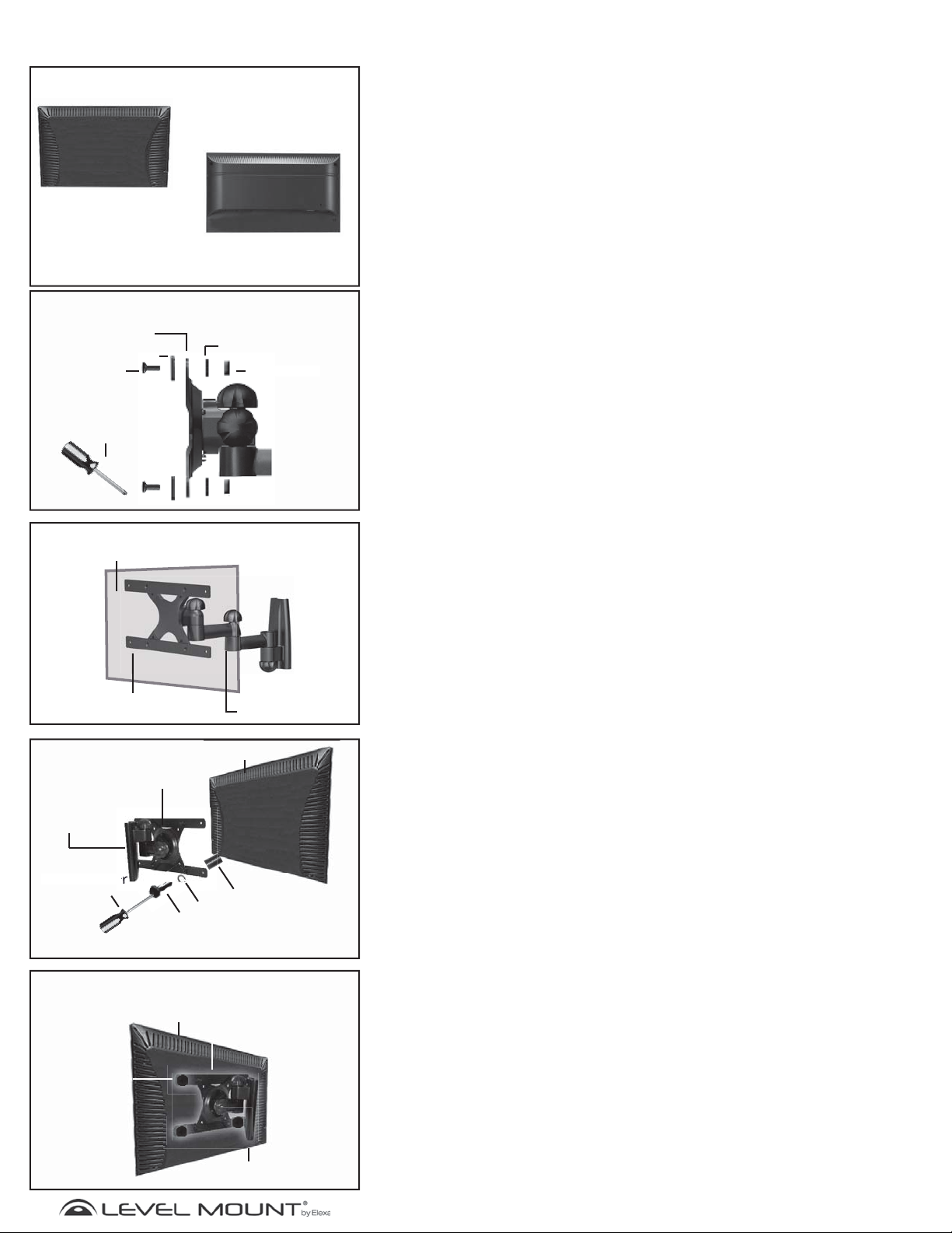
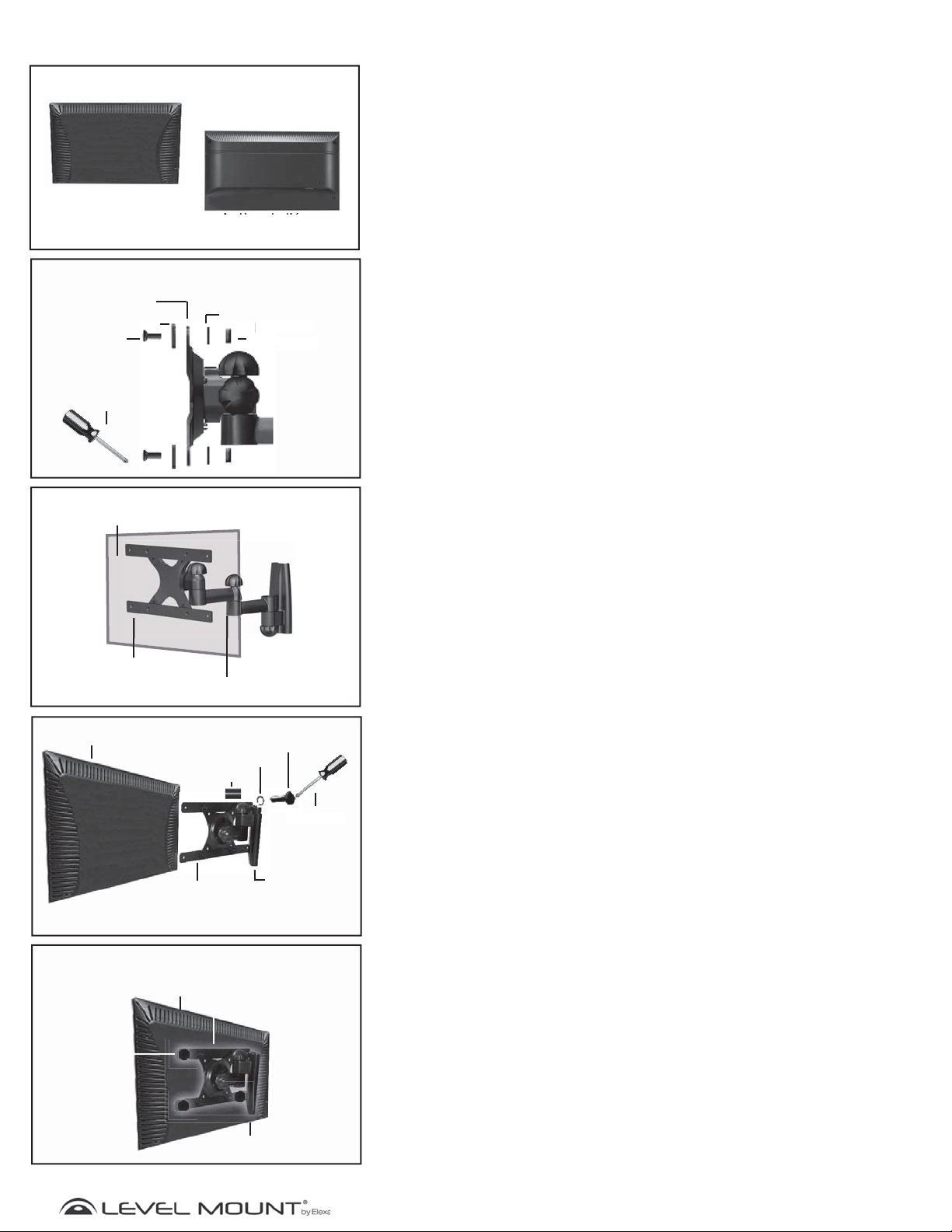
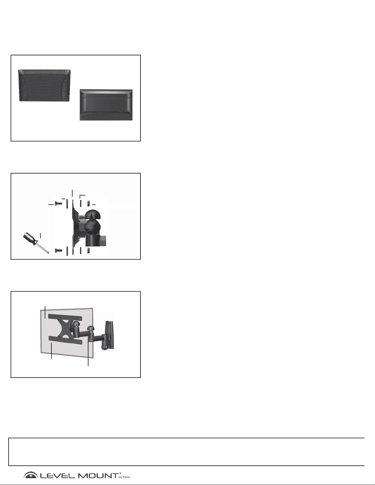
Step 1 – Selecting the Correct Hardware Based on Flat
Panel Monitor Back
Before beginning the installation, determine if the Flat Panel Monitor has a flat
back or a recessed back as shown in Figure 1. If you have a recessed back Flat
Panel Monitor you may need to use the spacers (Bag 1) as shown in Figure 4 or
6. The spacer is used to fill the recessed area of the Flat Panel Monitor so that
the Flat Panel Monitor Bracket is fully supported and flush with the back of the
Flat Panel Monitor.
Step 2 - Adapter Arm Installation (if needed)
If the holes in the Flat Panel Monitor Bracket do not line up with the holes in the
back of the Flat Panel Monitor, do not drill. Instead, follow these instructions for
the Adapter Arm Installation. Otherwise, skip to Step 3.
Note: The Adapter Arms can be used for Flat Panel Monitors with VESA
200mm x 100mm hole spacing; your Flat Panel Monitor manual/product
labels should specify the VESA hole spacing.
Step 2a - Attaching Adapter Arms to Flat Panel Monitor
Bracket
Attach the first set of Adapter Arms to the Flat Panel Monitor Bracket using the
following hardware as shown in Figure 2:
• Phillips Bolt M4 (Bag 4)
• Adapter Arms
• Flat Panel Monitor Bracket
• Lock Washers M4 (Bag 4)
• Hex Nut M4 (Bag 4)
Adjust the screws in Figure 2 to move the Adapter Arms to align with the VESA
holes on the back of the Flat Panel Monitor.
Adapter Arm
Figure 4
Adapter Arms
Monitor
Bracket
Phillips
Screwdriver
M4/M5 bolt
*Only use Spacer if Monitor has a recessed back
Monitor Bracket
Flat Back Monitor
Spacer
(If necessary)*
M4/M5 Washer
Figure 5
Flat Back Monitor
Adapter Arms
Step 2b - Completed Adapter Arm Attachment
Both Adapter Arms should be attached in the same manner. When completed it
will look like the photo as show in Figure 3.
Step 2c - Attaching Adapter Arms to the back of the Flat
Panel Monitor
There are bolts of varying lengths included in this package, located in (Bags
1 and 2). Please use the bolt with the appropriate length for your Flat Panel
Monitor.
• Bolt M4 (Bag 1) or Bolt M5 (Bag 2)
• Washer M4 (Bag 1) or Washer M5 (Bag 2)
• An additional Washer may be needed to prevent the bolt head from recessing
into the back of the Flat Panel Monitor
• Adapter Arm
• Spacer (If necessary) (Bag 1) (The Spacer is used to fill the recessed area
of the Flat Panel Monitor so that the Flat Panel Monitor Bracket is fully
supported and flush with the back of the Flat Panel Monitor).
To attach the Adapter Arms to the back of the Flat Panel Monitor, attach the
Adapter Arms horizontally to the Monitor Bracket using the hardware described
above, placing the 2 Bolts for each arm through the holes of the Adapter Arms
and carefully threading the bolts into the holes in the back of the Flat Panel
Monitor. If there is any resistance remove the bolt immediately and select the
correctly sized bolt that enables a secure and snug fit.
M4/M5 Bolt
Monitor Bracket
Tighten the bolts snugly to the back of the Flat Panel Monitor as shown in Figure
5. Then skip to Step 4.
Caution: Only tighten bolts until they are secure, do not over-tighten.
www.levelmount.com
5
©2011 Level Mount - Patents Pendin
1-888-229-1459
EU: +0044 844 567 2657
UK: 0844 567 2657
Page 6
g
Assembly/Installation
ol
t
pp
Flat Back Monitor
Figure 6
M4/M5 Washer
Spacer
M4/M5 bolt
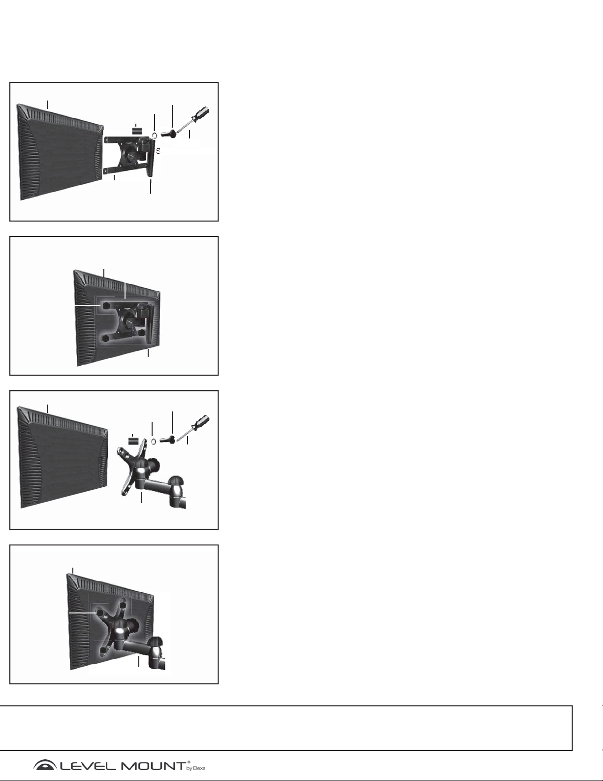
Step 3 – Attaching Flat Panel Monitor Bracket to Back of
Flat Panel Monitor
There are bolts of varying lengths included in this package, located in (Bags 1 and
2). Please use the bolt with the appropriate length for your Flat Panel Monitor.
Phillips
Screwdriver
Monitor Bracket
Only use Spacer if Monitor has a recessed back
Flat Back Monitor
M4/M5
Bolt
Figure 7
Monitor Bracket
Figure 8
Desk Top
Arm
Thin Desk
To p
Desk Top
Arm
Thick Desk
To p
• Bolt M4 (Bag 1) or Bolt M5 (Bag 2)
• Washer M4 (Bag 1) or Washer M5 (Bag 2)
• An additional Washer may be needed to prevent the bolt head from recessing
into the back of the Flat Panel Monitor
• Adapter Arm
• Spacer (Bag 1) Only needed if the Flat Panel Monitor has a recessed back.
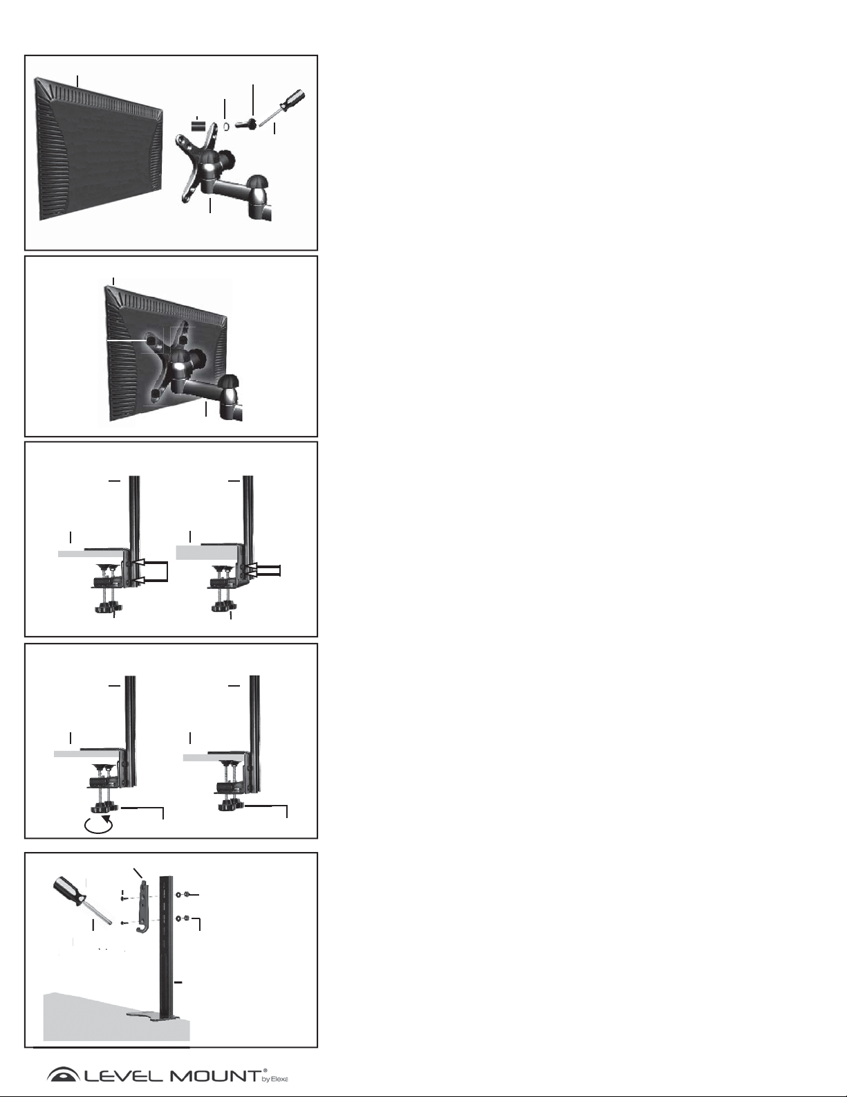
To attach the Flat Panel Monitor Bracket to the back of the Flat Panel Monitor,
place 4 Bolts through the holes of the Flat Panel Monitor Bracket and carefully
thread them into the holes in the back of the Flat Panel Monitor. If there is any
resistance remove the bolt immediately and select the correctly sized bolt that
enables a secure and snug fit.
Tighten the bolts snugly to the back of the Flat Panel Monitor as shown in Figure 7.
Caution: Only tighten bolts until they are secure, do not over-tighten.
Step 4 – Securing the Desktop Arm and Arm Plate to
the Desk
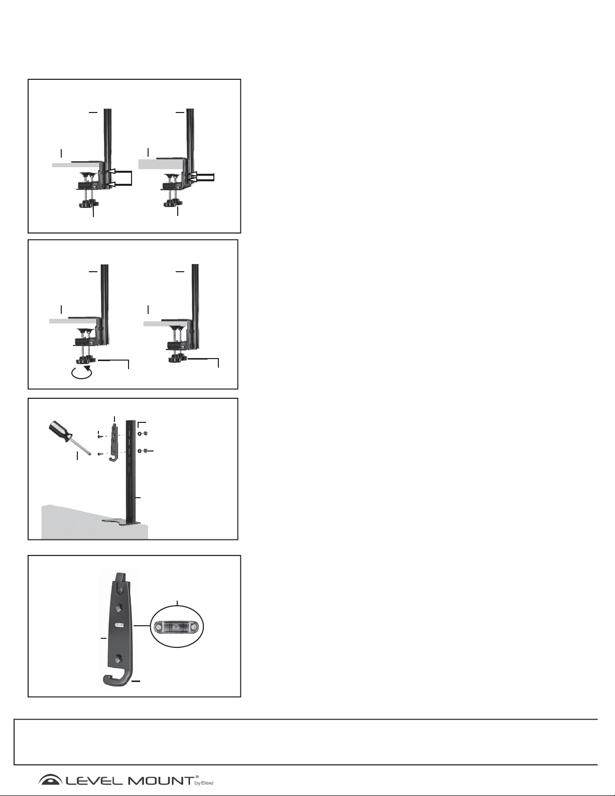
Place the L-Bracket portion of the Desktop Arm on the desk as shown in
Figure 8. Turn the Securing Knobs clockwise until they are snug against the
desktop as shown in Figure 9.
L-Bracket
Bolts
Securing Knobs Securing Knobs
Figure 9
Desk Top
Arm
Desk Top
Arm Plate
M6 Bolt
Phillips
Screwdriver
Securing Knobs
s
Desk Top
Arm
Desk Top
Securing Knobs
Figure 10
Washer
16mmx6.3mmx1.2mm
M6 Hex
Nut
L-
L-Bracket
Bolts
In most cases the L-bracket bolts will be the correct depth. However, in some
cases the L-Bracket will need to be adjusted due to the depth of the desk top.
To adjust the bolts in the L-Bracket simply unscrew the L-Bracket bolts and fit
to the desk. Then tighten the bolts securely.
Caution: The L-bracket only fits a ledge that is between .5 and 2.5
inches thick, and at least 2 inches deep. If the desktop ledge is made
out of a material other than solid wood, you will need to make sure
that the ledge can support the weight of the mount and Monitor/
Display placed on the desktop.
Attach the Arm Plate to the holes in the Desktop Arm, at the desired height
depending on the size of the Flat Panel Monitor, as shown in Figure 10 using
the hardware from (Bag 3) as follows:
• Bolt M6 (Bag 3)
• Arm Plate
• Desktop Arm
• Washer 16mm x 6.3mm x 1.2mm (Bag 3)
• Hex Nut M6 (Bag 3)
Desk Top Arm
Desk Top
www.levelmount.com
6
©2011 Level Mount - Patents Pendin
1-888-229-1459
EU: +0044 844 567 2657
UK: 0844 567 2657
Page 7
g
Assembly/Installation
Built-in Bubble
Level/
p
p
Figure 11
Arm
Plate
Monitor
Monitor
Bracket
Desk Top
Built-in Bubble
Level/
Spirit Level
Cord
Management
Figure 12
Bubble
Arm Plate
Cord
Management
Desk Top
Step 4 – (Continued)
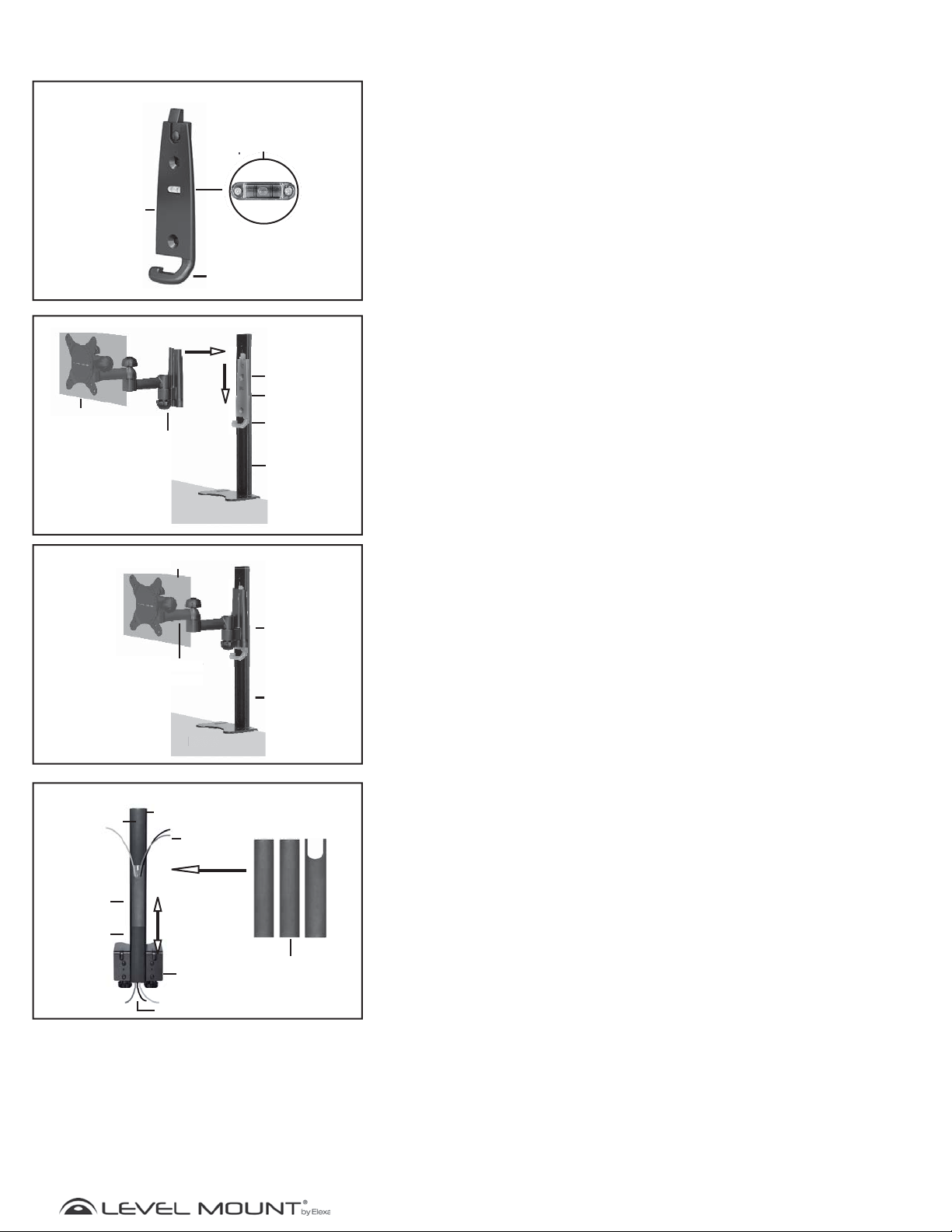
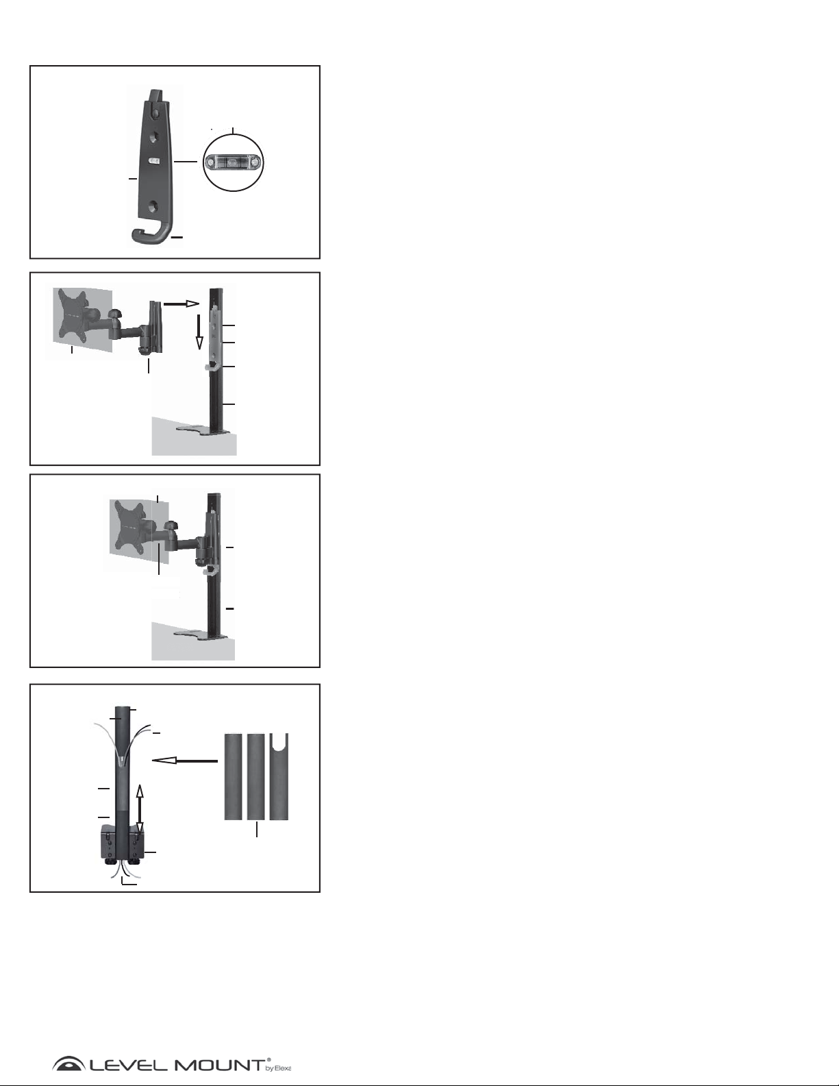
The Arm Plate has a Built-in Bubble Level/Spirit Level to ensure the Flat Panel
Monitor is level when attached to the Desktop Arm. The Cord Management
hook at the bottom of the Arm Plate, gathers the cords from the Flat Panel
Monitor to feed through the Cord Cover as shown in Figure 11.
Lift the Flat Panel Monitor with the Flat Panel Bracket attached, higher than
the Arm Plate, which is attached to the Desktop Arm. Place the back of the
Flat Panel Bracket over the Arm Plate and slide the Flat Panel Bracket down
until it clicks together with the Arm Plate as shown in Figure 12.
The Flat Panel Bracket secured to the Arm Plate and Desktop Arm appears as
shown in Figure 13.
Level
Arm
Cord Cover
Cord Cover
Cord Cover
Monitor
Monitor
nitor
Bracket
cket
Figure 14
Desk Top Arm
L-Bracket
Cords
Desk
esk
Figure 13
Arm
Plate
Desk Top
Arm
Step 5 – Organizing Monitor Cords
To organize and hide the Flat Panel Monitor’s cords, slide the bottom two
sections of Cord Cover down off the back of the Desktop Arm as shown in
Figure 14 (The top section remains in place). Feed the cords from the Flat Panel
Monitor into the hollow of the Desk Top Arm. When cords are in place, slide the
two sections previously removed back up into the channels of the Desk Top
Arm, starting with the cut-out scoop then the straight section. Push up until the
cut-out section meets the top section of Cord Cover.
Cord Cover
Sections
www.levelmount.com
7
©2011 Level Mount - Patents Pendin
1-888-229-1459
EU: +0044 844 567 2657
UK: 0844 567 2657
Page 8
g
¿Necesita ayuda?
Consejos útiles
Si tiene alguna duda sobre cómo instalar su soporte de pared para televisión, por favor vaya a www.
levelmount.com para ver los tutoriales del producto.
Contactar con el Servicio de Atención al Cliente Level Mount
Si tiene usted cualquier duda, nuestro departamento de Atención al Cliente le ayudará encantado las
24 horas del día, 7 días a la semana, todos los días del año. Para ponerse en contacto con el Servicio de
Atención al Cliente Level Mount:
• Desde Estados Unidos, marque: 1-888-229-1459
• Desde Europa, marque: +0044 844 567 2657
• Desde Reino Unido, marque: 0844 567 2657
• Envíe un e-mail a Level Mount a [email protected]
NO DEVUELVA ESTE PRODUCTO A LA TIENDA O WEB DONDE LO COMPRÓ
Si cree usted que su producto está defectuoso, que le falta una parte o tiene una parte rota, o si está
teniendo problemas para montarlo, póngase por favor directamente en contacto con Level Mount, las
24 horas del día, 7 días a la semana, 365 días al año, en los teléfonos indicados arriba, y resolveremos
su problema rápida y efi cazmente.
¿Qué herramientas necesita?
Incluidas
Nivel de burbuja
incorporadol
Nivel
No incluidas
Destornillador
Phillips
www.levelmount.com
8
©2011 Level Mount - Patents Pendin
1-888-229-1459
EU: +0044 844 567 2657
UK: 0844 567 2657
Page 9
g
¿Qué hay en la caja?
Soporte de
Pantalla Plana
(DSK30DJ en la foto)
Brazos Placa
Cable de la Cubierta
(Viene pre-adjunta en la parte
posterior de Escritorio Brazo)
Bolsa 1
(4) M4
Arandelas
(4)
15.9mm
(4) M4 x12mm
Tornillos Phillips
(4) M4 x 20mm
Tornillos Phillips
(4) M4 x 30mm
Tornillos Phillips
Separadores
Soporte TV con
respaldo plano
Soporte TV con
respaldo
hueco
Brazos Adaptador
Escritorio Brazo
Bolsa 2
(4) M5
Arandelas
(4) M5 x 12mm
Tornillos Phillips
(4) M5 x 20mm
Tornillos Phillips
(4) M5 x 30mm
Tornillos Phillips
Soporte TV con
respaldo plano
Soporte TV con
respaldo
hueco
Bolsa 3
(2)
Arandelas
16mm x 6.3mm x 1.2mm
(2)
Tornillos Phillips
M6 x 22mm
Bolsa 4
(2) M6
Tuercas
9
(4) M4
Tuercas
Tornillos Phillips Kit Adaptor
(4)
Tornillos Phillips
M4 x 12mm
(4) M4
Arandelas de
presión
©2011 Level Mount - Patents Pendin
www.levelmount.com
1-888-229-1459
EU: +0044 844 567 2657
UK: 0844 567 2657
Page 10
g
Cómo empezar
¡CUIDADO!
!
Este escritorio montaje fue diseñado específicamente para llevar 10 “- 30” (25,4 cm - 76,2 cm),
monitores de pantalla plana y un peso máximo de hasta 35 libras (16kg). de utilizar este producto con
un monitor de pantalla plana más pesado que el peso máximo, o que exceda estas dimensiones, puede
resultar en lesiones personales graves y daños al equipo y la propiedad.
1. No empiece a instalar el escritorio montaje hasta no haber leído y comprendido las instrucciones y advertencias de
estas Instrucciones de Instalación. Si no lee, comprende completamente y sigue estas instrucciones podría provocar
lesiones personales serias o daños al equipo y propiedad. Es responsabilidad del instalador asegurarse de que todos
los componentes estén correctamente montados e instalados de acuerdo con las instrucciones proporcionadas.
2. Si no encuentra la respuesta a una pregunta en estas Instrucciones de Instalación, revise por favor las preguntas
frecuentes que encontrará en el apartado “Consejos Útiles” de la página de detalles del escritorio montaje, o póngase
en contacto con nosotros en los teléfonos que encontrará más adelante, en el apartado “¿Necesita ayuda?”. Si no está
seguro de haber comprendido alguno de los pasos de estas instrucciones, o de su capacidad para instalar el escritorio
montaje de manera segura y eficaz, debería ponerse en contacto con un profesional.
3. Este escritorio montaje contiene piezas pequeñas que podrían ser peligrosas; manténgalas fuera del alcance de los
niños.
4. No utilice nunca este escritorio montaje en el exterior. El uso de este producto en el exterior podría ocasionar fallos y
provocar lesiones personales serias o daños al equipo y propiedad.
5. El escritorio de montaje debe ser conectado a un escritorio sólo como se especifica en estas instrucciones de
instalación. no utilizar el escritorio de montaje para otros dispositivos distintos de los especificados en estas
instrucciones.
6. Asegúrese de haber apretado bien todos los tornillos antes de cargar todo el peso del monitor sobre el soporte de
escritorio montaje. Apriete bien los tornillos, pero sin llegar a pasarse de rosca. En cuanto vea que el tornillo está
pegado al monitor y le cuesta girar el destornillador, deténgase; de lo contrario, corre el riesgo de pasarse de rosca,
lo que podría provocar daños en el escritorio montaje para monitor, reduciendo considerablemente su capacidad de
sujeción. Es posible que, de vez en cuando, necesite revisar que los tornillos están debidamente apretados.
7. Los tornillos deberían encajar completa y fácilmente en los agujeros del monitor. Si alguno de los tornillos
proporcionados no encaja bien en el escritorio montaje, el instalador no deberá taladrar agujeros en el monitor bajo
ningún concepto, ni en ninguno de los componentes del escritorio montaje. Si usa tornillos de un tamaño no adecuado
podría provocar daños en el monitor.
8. No levante más peso del que pueda soportar. Se necesitan al menos dos personas para levantar y colocar el televisor
sobre el soporte de pared.
9. Antes de instalar su escritorio montaje, asegúrese de tener todas las partes indicadas en estas Instrucciones de
Instalación, y de que estén en buenas condiciones. No utilice nunca partes dañadas, ni intente instalar el escritorio
montaje sin tener todos los elementos necesarios.
10. El instalador es responsable de escoger el lugar y la superficie más adecuados para instalar este escritorio montaje,
de manera que quede perfectamente fijado a la escritorio montaje. También es responsabilidad del instalador
asegurarse de que el monitor esté correcta y adecuadamente fijado en el escritorio montaje, utilizando sólo los
cierres y componentes incluidos, así como de comprobar que los tornillos y cables no entren en contacto con cables,
tuberías o partes de metal dentro de la escritorio montaje (puesto que podría dañar dichos elementos o provocar un
cortocircuito).
11. Level Mount ha hecho todo lo posible por que estas Instrucciones de Instalación sean lo más precisas y completas posible.
Sin embargo, Level Mount no puede asegurarle que la información contenida en las mismas cubra todos los detalles,
condiciones o variaciones, ni que cubra todas los posibles incidentes relacionados con la instalación, montaje o uso de este
producto. Level Mount no garantiza, de manera expresa ni implícita, que la información contenida en este documento sea
exacta, completa o suficiente. Level Mount no se responsabiliza de ningún daño o lesión causado por el montaje, instalación
o uso indebido.
10
www.levelmount.com
1-888-229-1459
EU: +0044 844 567 2657
©2011 Level Mount - Patents Pendin
UK: 0844 567 2657
Page 11
g
Montaje/Instalación
T
rr
Imagen 1
Respaldo plano
Respaldo hueco
Soporte de
Pantalla Plana
Brazos Adaptador
M4 Tornillo
Destornillador
Phillips
Monitor de
Pantalla Plana
Imagen 2
Imagen 3
M4
Arandelas
de Presión
M4
Tuercas
4
Paso 1 – Escoja el soporte correcto en función de la parte
trasera de su televisor
Antes de empezar la instalación, compruebe si la parte trasera de su televisor es
plana o hueca, tal y como muestra la Imagen 1. Si la parte trasera de su televisor es hueca, es posible que necesita utilizar los separadores (Bolsa 1), tal y como
muestran las Imágenes 4 y 6. Los separadores sirven para rellenar el hueco que
queda en la parte trasera de su televisor, de manera que el soporte quede perfectamente fijado a la parte trasera de su televisor.
Paso 2 - De instalación del adaptador del brazo (si es
necesario)
Si los agujeros en el Soporte de Pantalla Plana no se alinean con los agujeros
en la parte posterior del monitor de pantalla plana, no taladre. en cambio, siga
estas instrucciones para la instalación del brazo adaptador. de lo contrario, vaya
al paso 3
Note: Los brazos adaptador se puede utilizar para los monitores de pantalla
plana con VESA 200mm x 100mm espacio entre los orificios; el manual
de su monitor de panel plano
Paso 2a - Fijar los brazos adaptador para Soporte de
Pantalla Plana
Fijar los brazos adaptador para Soporte de Pantalla Plana adjuntar la primera
serie de las armas adaptador para el soporte de panel del monitor plano con el
siguiente hardware como se muestra en la figura 2:
• Tornillo de Phillips M4 (Bolsa 4)
• Brazos Adaptador
• Soporte de Pantalla Plana
•
Arandelas de Presión
•
Tuercas
Ajuste los tornillos en la figura 2 para mover los brazos adaptador para alinear con
los orificios VESA en la parte posterior del monitor de pantalla plana.
M4 (Bolsa 4)
M4 (Bolsa 4)
Paso 2b - Completado apego adaptador de brazo
Brazos Adaptador
Imagen 4
Brazos Adaptador
Soporte
de Pantalla
Plana
Destornillador
Phillips
M4/M5 Tornillo
Utilice el separador sólo en caso de que la parte trasera de
Respaldo plano
M4/M5
su televisor sea hueca
Soporte de
Pantalla Plana
Separador
(si es necesario)
Arandelas
Imagen 5
Respaldo plano
Brazos Adaptador
M4/M5
Tornillo
Ambos brazos adaptador debe atribuirse manera semejante. cuando
completado parece la foto como mostrar en figura 3.
Paso 2c - Fijar los brazos del adaptador a la parte
posterior de la pantalla plana del monitor
Hay tornillos de diferentes longitudes incluidas en este paquete, que se
encuentra en (bolsas de 1 y 2). por favor, utilice el perno con la longitud
adecuada para su monitor de pantalla plana.
• Tornillo M4 (Bolsa 1) o Tornillo M5 (Bolsa 2)
•
Arandelas
• Una arandela adicional puede ser necesaria para evitar que la cabeza del
perno de empotrar en la parte posterior del monitor de pantalla plana
• Brazos Adaptador
• Separador (si es necesario) (Bolsa 1) - El espaciador se utiliza para rellenar
el área empotrada de la pantalla plana del monitor de forma que el soporte
de panel del monitor plano es totalmente compatible y al ras con la parte
posterior del monitor de pantalla plana.
Para conectar los brazos adaptador a la parte posterior del monitor de pantalla
plana, coloque los brazos horizontalmente adaptador al soporte de monitor
utilizando el hardware descrito anteriormente, colocando los 2 tornillos para
cada brazo a través de los orificios de los brazos adaptador de rosca y con
cuidado los tornillos en el agujeros en la parte posterior del monitor de pantalla
plana. si hay alguna resistencia a quitar el perno inmediatamente y seleccionar
el tamaño correcto del perno que permite un ajuste seguro y cómodo.
Apretar los tornillos cómodamente en la parte posterior del monitor plano, como
se muestra en la figura 5. A continuación, vaya al paso 4.
M4 (Bolsa 1) or
Arandelas
M5 (Bolsa 2)
Cuidado:
Soporte de Pantalla
Plana
Apriete los tornillos sólo hasta que estén seguros, con cuidado
de no apriete en exceso.
11
www.levelmount.com
1-888-229-1459
EU: +0044 844 567 2657
©2011 Level Mount - Patents Pendin
UK: 0844 567 2657
Page 12
g
Bolt
pp
Montaje/Instalación
Flat Back Monitor
Only use Spacer if Monitor has a recessed back
Flat Back Monitor
M4/M5
Bolt
Figure 6
M4/M5 Washer
Spacer
Monitor Bracket
Figure 7
M4/M5 bolt
Phillips
Screwdriver
Paso 3 - Fijar el Soporte de Pantalla Plana en la parte
posterior de la Monitor de Pantalla Plana
No son tornillos de diferentes longitudes incluidas en este paquete, que se
encuentra en (Bolsas 1 y 2). por favor, utilice el tornillos con la longitud adecuada
para su monitor de pantalla plana.
• Tornillo M4 (Bolsa 1) or Tornillo M5 (Bolsa 2)
• Arandela M4 (Bag 1) or Arandela M5 (Bag 2)
• Una arandela adicional puede ser necesaria para evitar que la cabeza del
• Brazos Adaptador
• Separador (si es necesario) (Bolsa 1) - El espaciador se utiliza para rellenar
Adjuntar fije el soporte de panel del Monitor de Pantalla Plana en la parte posterior
del monitor de pantalla plana, coloque los 4 tornillos a través de los orificios del
soporte del panel del monitor plano y cuidadosamente los hilos en los agujeros en
la parte posterior del monitor de pantalla plana. si hay alguna resistencia a quitar
el perno inmediatamente y seleccionar el tamaño correcto del perno que permite
un ajuste seguro y cómodo.
Apretar los tornillos cómodamente en la parte posterior del monitor plano, como
se muestra en la figura 7.
perno de empotrar en la parte posterior del monitor de pantalla plana
el área empotrada de la pantalla plana del monitor de forma que el soporte
de panel del monitor plano es totalmente compatible y al ras con la parte
posterior del monitor de pantalla plana.
Monitor Bracket
Figure 8
Desk Top
Arm
Thin Desk
To p
Securing Knobs Securing Knobs
Desk Top
Arm
Thick Desk
To p
L-Bracket
Bolts
Figure 9
Desk Top
Arm
Desk Top
Desk Top
Arm
Desk Top
L-Bracket
Bolts
Cuidado:
Apriete los tornillos sólo hasta que estén seguros, con cuidado
de no apriete en exceso.
Paso 4 – Securing the Desktop Arm and Arm Plate to
the Desk
Place the L-Bracket portion of the Desktop Arm on the desk as shown in
Figure 8. Turn the Securing Knobs clockwise until they are snug against the
desktop as shown in Figure 9.
In most cases the L-bracket bolts will be the correct depth. However, in some
cases the L-Bracket will need to be adjusted due to the depth of the desk top.
To adjust the bolts in the L-Bracket simply unscrew the L-Bracket bolts and fit
to the desk. Then tighten the bolts securely.
Caution: The L-bracket only fits a ledge that is between .5 and 2.5
Attach the Arm Plate to the holes in the Desktop Arm, at the desired height
depending on the size of the Flat Panel Monitor, as shown in Figure 10 using
the hardware from (Bag 3) as follows:
• Bolt M6 (Bag 3)
• Arm Plate
• Desktop Arm
• Washer 16mm x 6.3mm x 1.2mm (Bag 3)
• Hex Nut M6 (Bag 3)
inches thick, and at least 2 inches deep. If the desktop ledge is made
out of a material other than solid wood, you will need to make sure
that the ledge can support the weight of the mount and Monitor/
Display placed on the desktop.
Securing Knobs
Arm Plate
M6 Bolt
Phillips
Phillips
Screwdriver
Desk Top
Securing Knobs
Figure 10
Washer
16mmx6.3mmx1.2mm
M6 Hex
Nut
Desk Top Arm
12
www.levelmount.com
1-888-229-1459
EU: +0044 844 567 2657
©2011 Level Mount - Patents Pendin
UK: 0844 567 2657
Page 13
g
nitor ket
Built-in Bubble
Level/
p
p
Montaje/Instalación
Figure 11
Arm
Plate
Monitor
Monitor
Bracket
Desk Top
Built-in Bubble
Level/
Spirit Level
Cord
Management
Figure 12
Bubble
Arm Plate
Cord
Management
Desk Top
Step 4 – (Continued)
The Arm Plate has a Built-in Bubble Level/Spirit Level to ensure the Flat Panel
Monitor is level when attached to the Desktop Arm. The Cord Management
hook at the bottom of the Arm Plate, gathers the cords from the Flat Panel
Monitor to feed through the Cord Cover as shown in Figure 11.
Lift the Flat Panel Monitor with the Flat Panel Bracket attached, higher than
the Arm Plate, which is attached to the Desktop Arm. Place the back of the
Flat Panel Bracket over the Arm Plate and slide the Flat Panel Bracket down
until it clicks together with the Arm Plate as shown in Figure 12.
The Flat Panel Bracket secured to the Arm Plate and Desktop Arm appears as
shown in Figure 13.
Level
Arm
Cord Cover
Cord Cover
Cord Cover
Monitor
Monitor
Bracket
Desk
Figure 14
Desk Top Arm
L-Bracket
Cords
Figure 13
Arm
Plate
Desk Top
Arm
Step 5 – Organizing Monitor Cords
To organize and hide the Flat Panel Monitor’s cords, slide the bottom two
sections of Cord Cover down off the back of the Desktop Arm as shown in
Figure 14 (The top section remains in place). Feed the cords from the Flat Panel
Monitor into the hollow of the Desk Top Arm. When cords are in place, slide the
two sections previously removed back up into the channels of the Desk Top
Arm, starting with the cut-out scoop then the straight section. Push up until the
cut-out section meets the top section of Cord Cover.
Cord Cover
Sections
www.levelmount.com
13
©2011 Level Mount - Patents Pendin
1-888-229-1459
EU: +0044 844 567 2657
UK: 0844 567 2657
Page 14
g
Besion d’aide?
Conseils Utiles
Si vous avez des questions sur l’installation de votre TV Support Mural, s’il vous plaît aller à www.
levelmount.com pour voir les tutoriels produit.
Contacts Level Mount Service à la Clientèle
Si vous avez des questions, notre formation Service à la clientèle est heureux de vous aider, 24 heures
par jour, 7 jours par semaine, tous les jours de l’année. Contactez Level Mount Service à la clientèle
comme suit:
• Dans les États-Unis appellez: 1-888-229-1459
• En Europe appelez: +0044 844 567 2657
• Dans le Royaume-Uni appelez: 0844 567-2657
• E-mail Level Mount au [email protected]
NE PAS RETOURNER CE PRODUIT SUR LE WEBSITE OU MAGASIN DE VOUS L’AVEZ ACHETÉ
Si vous croyez que le produit est défectueux, a une partie manquante ou cassée ou ont de la
diffi culté avec l’assemblage, s’il vous plaît contacter Level Mount direcement 24 heures par jour, 7
jours par semaine, 365 jours par an comme indiqué ci-dessus, pour une solution rapide et effi cace à
votre problème.
Outils Nécessaires
Inclus
Niveau à bulle
Ne sont pas compris
Tournevis
Phillips
14
www.levelmount.com
1-888-229-1459
EU: +0044 844 567 2657
©2011 Level Mount - Patents Pendin
UK: 0844 567 2657
Page 15
g
Qu’y a-t-il dans la boîte?
Support d’écran plat
(DSK30DJ est Montré)
Platine du bras
Goulotte de protection du
cordon
(Livré pré-fixée au dos de Support
pour Bureau)
Sachet 1
(4) M4 Rondelle
Frein
(4) M4X12mm
Boulon
Cruciforme
(4) M4X20mm
Boulon
Cruciforme
(4) M4X30mm
Boulon
Cruciforme
(4) Rondelle
d’espacement 15,9mm
Équipement
arrière plat
Équipement
arrière convexe
ou concave
Bras adaptateurs
Support pour
Bureau
Sachet 2
(4) M5 Rondelle
Frein
(4) M5X12 mm
Boulon
Cruciforme
(4) M5X20 mm
Boulon
Cruciforme
(4) M5X30 mm
Boulon
Cruciforme
Équipement
arrière plat
Équipement
arrière convexe
ou concave
Sachet 3
(2) Rondelle
16mmx6,3mmx1,2mm
(2) M6X22mm
Boulon Cruciforme
(2) M6 Écrou
hexagonal
Sachet 4
(4) M4 Écrou
hexagonal
15
Kit d’adaptation Boulon
Phillips
(4) M4X12mm
Boulon Cruciforme
(4) M4 Rondelle Frein
©2011 Level Mount - Patents Pendin
www.levelmount.com
1-888-229-1459
EU: +0044 844 567 2657
UK: 0844 567 2657
Page 16
g
Pour Commencer
!
AVERTISSEMENT !
Ce support de moniteur a été spécialement conçu pour supporter des écrans plats de 25,4 cm à 76,2
cm (10 po à 30 po) pouvant peser jusqu’à 16 kg (35 lb). Si vous utilisez ce produit pour des écrans
plats excédant le poids maximum, ou les dimensions indiquées, cela peut engendrer des blessures
sérieuses ainsi que des dommages à l’équipement et aux biens immobiliers.
1. N’entreprenez pas l’installation du support de moniteur tant que vous n’avez pas lu ni compris les instructions
et les avertissements figurant dans les instructions de montage. Si vous n’avez pas lu, compris et suivi
soigneusement les instructions, cela pourra engendrer des blessures corporelles sérieuses ainsi que des
dommages à l’équipement et aux biens immobiliers. L’installateur doit s’assurer que tous les composants
sont correctement montés et installés en suivant les instructions fournies.
2. Si vous avez des questions qui ne semblent pas trouver de réponse dans les présentes Instructions
d’installation, veuillez contactez-nous tel qu’indiqué dans la section « Besoin d’aide » ci-dessus. Si vous
avez un doute concernant une quelconque étape de ces instructions ou sur votre capacité à installer le
support de moniteurs de manière sûre, vous devez demander l’aide d’un professionnel qualifié.
3. Ce support de moniteur comporte de petites pièces qui peuvent s’avérer dangereuses en cas d’ingestion.
Veuillez garder ces articles hors de portée des enfants.
4. Le support de moniteur ne devra en aucun cas être utilisé à l’extérieur. L’utilisation de ce produit à l’extérieur
pourrait provoquer une défaillance du produit et entraîner des blessures graves ou des dommages à
l’équipement et aux biens immobiliers.
5. Le support mural de moniteur doit être uniquement fixé à un moniteur tel qu’indiqué dans les Instructions de
montage. N’utilisez pas le support de moniteur pour des appareils autres que ceux précisés aux présentes
instructions.
6. Assurez-vous que les vis et les boulons sont serrés avant de faire supporter le poids d’un écran plat aux
supports de moniteurs. Serrez fermement les vis et les boulons, mais ne serrez pas trop. Une fois que la vis
est à plat contre l’écran plat et qu’il devient plus difficile de tourner le tournevis, arrêtez ; si vous continuez,
vous pourriez trop serrer le boulon. Dans ce cas, vous pourriez endommager le support d’écran, ce qui
réduirait considérablement son pouvoir de maintien. Il est possible de devoir resserrer périodiquement.
7. Les vis doivent facilement et complètement passer dans les trous de montage du moniteur. Si l’une des vis
fournies n’est pas compatible avec les systèmes du support de moniteur, l’installateur ne doit en aucun cas
percer de trous dans l’écran plat ni dans un composant du support moniteur. L’utilisation de vis d’une taille
non adaptée peut endommager l’écran plat.
8. Ne soulevez pas plus de poids que vous ne pouvez supporter. Si nécessaire, deux personnes devront porter
l’écran plat pour le positionner sur le support.
9. Avant installation, assurez-vous que toutes les pièces du support de moniteur mentionnées dans la notice
d’installation sont présentes et en bon état. N’utilisez jamais de pièces abîmées et n’essayez jamais
d’installer le support de moniteur si vous n’avez pas toutes les pièces requises.
10. Il est de la responsabilité de l’installateur de choisir l’emplacement de l’installation et la surface d’appui sur
laquelle monter ce support pour moniteur, et de s’assurer que le support est correctement fixé au moniteur.
Il est aussi de la responsabilité de l’installateur de s’assurer que l’écran plat est correctement et solidement
fixé au support en utilisant uniquement les attaches et les composants ci-joints, et de vérifier que les vis et
cordons ne sont pas en contact avec des fils électriques, des tuyaux ou des pièces métalliques (car cela
pourrait endommager ces éléments ou causer un choc électrique).
11. Level Mount se sont efforcées de rendre cette Notice d’installation précise et complète. Cependant, Level
Mount ne prétend pas que les informations contenues ici couvrent tous les détails, conditions ou variations,
ou qu’elles prévoient toutes les éventualités en rapport avec l’installation, le montage ou l’utilisation de
ce produit. Level Mount ne fait aucune déclaration ni garantie, de manière explicite ou implicite, quant à
l’exactitude, l’exhaustivité ou la suffisance des informations contenues dans ce document. Level Mount
n’est pas responsable d’aucun dommage ou préjudice causé par un montage, assemblage incorrect, une
installation ou une utilisation incorrecte.
16
www.levelmount.com
1-888-229-1459
EU: +0044 844 567 2657
©2011 Level Mount - Patents Pendin
UK: 0844 567 2657
Page 17
g
Assemblage/Installation
Arrière écran
plat
Support
d’écran plat
Bras adaptateur
M4
Boulon
Tournevis
cruciforme
Écran plat
Figure 1
Arrière de l’écran
convexe ou concave
Figure 2
M4 Rondelle frein
Figure 3
M4 Écrou
M4
hexagonal
hex
Étape 1 – Choix du matériel approprié en fonction de la
surface arrière de l’écran plat
Avant de commencer l’installation, il faut déterminer si l’arrière de l’écran plat
est concave ou convexe tel qu’illustré en Figure 1. Si votre écran possède une
surface arrière convexe ou concave, vous pourriez devoir utiliser les entretoises
(Sachet 1) tel qu’illustré en Figure 4 ou 6. L’entretoise est utilisée pour remplir
la zone convexe ou concave de l’écran plat afin que le support s’encastre
totalement avec l’arrière de l’écran plat.
Étape 2 - Installation du bras adaptateur (si nécessaire)
Si les trous du support d’écran plat ne sont pas alignés avec les trous qui se
trouvent à l’arrière de l’écran, ne percez pas. Suivez plutôt ces instructions
relatives à l’installation du bras adaptateur. Autrement, passez à l’étape 3.
Note: Les bras adaptateurs peuvent être utilisés pour des écrans plats avec
un espacement du trou VESA de 200 mm x 100 mm ; le manuel/les
étiquettes produit de votre écran plat devraient préciser l’espacement
des trous VESA.
Étape 2a - Fixation des bras adaptateurs au support de
l’écran plat
Fixez le premier ensemble de bras adaptateurs au support d’écran plat en utilisant
les équipements suivants tel qu’illustré en Figure 2 :
• Boulon cruciforme M4 (Sachet 4)
• Bras adaptateurs
• Support d’écran plat
• Rondelles frein M4 (Sachet 4)
• Écrou hexagonal M4 (Sachet 4)
Bras adaptateur
Arrière de l’écran
plat
Bras adaptateurs
N’utilisez une entretoise que si l’arrière de votre
écran est convexe ou concave
Support d’écran
Figure 4
M4/M5
Rondelle
Rondelle
d’espacement
M4/M5 boulon
Tournevis
cruciforme
Support
d’écran
Figure 5
Arrière de l’écran
plat
Bras adaptateurs
Réglez les vis en Figure 2 pour déplacer les bras adaptateurs afin de les aligner
avec les trous VESA au dos de l’écran plat.
Étape 2b - Fixation du bras adaptateur complète
Les deux bras adaptateurs devront être fixés de la même manière. Lorsque cela
sera fait, ils devront apparaître comme indiqué en Figure 3.
Étape 2c - Fixation des bras adaptateurs à l’arrière de
l’écran plat
Ce paquet contient des boulons de différentes longueurs (Sachets 1 et 2).
Veuillez utiliser le boulon de la longueur appropriée à votre écran plat.
• Boulon M4 (Sachet 1) ou Boulon M5 (Sachet 2)
• Rondelle M4 (Sachet 1) ou Rondelle M5 (Sachet 2)
• Vous pourriez avoir besoin d’une rondelle supplémentaire pour
empêcher que la tête du boulon ne s’encastre dans l’arrière de votre écran plat
• Bras adaptateur
• Entretoise (Sachet 1) Seulement si la surface arrière de votre écran plat
est convexe ou concave.
Pour fixer les bras adaptateurs à l’arrière de l’écran plat, fixez horizontalement
les bras adaptateurs au support de l’écran en utilisant l’équipement décrit
ci-dessus, en plaçant les deux boulons de chacun des bras à travers les
trous des bras adaptateurs, et vissez soigneusement les boulons dans les
trous situés à l’arrière de l’écran plat. S’il y a une résistance, retirez le boulon
immédiatement et choisissez un boulon de bonne taille qui permette un
ajustement solide et sûr.
Serrez les boulons à l’arrière de l’écran sans trop forcer tel qu’illustré en Figure
5. Passez ensuite à l’étape 4.
M4/M5
Boulon
Support
d’écran
Avertissement : serrez seulement les boulons jusqu’à ce qu’ils soient
sécurisés, ne serrez pas trop.
www.levelmount.com
17
©2011 Level Mount - Patents Pendin
EU: +0044 844 567 2657
1-888-229-1459
UK: 0844 567 2657
Page 18
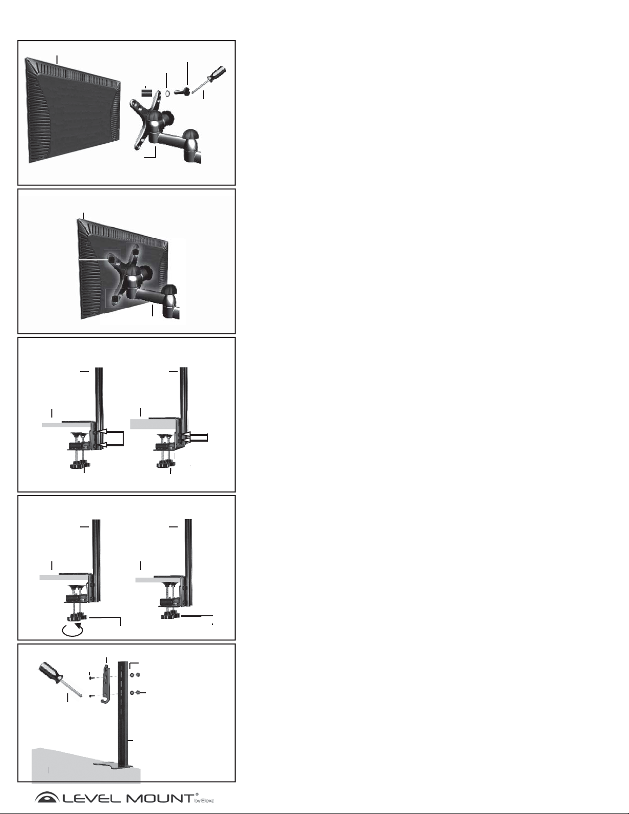
g
Assemblage/Installation
Arrière de l’écran
plat
N’utilisez une entretoise que si l’arrière de votre
écran est convexe ou concave
Arrière de
l’écran plat
M4/M5
Boulon
Figure 6
M4/M5 Rondelle
Rondelle
d’espacement
Support
d’écran
Figure 7
Support d’écran
M4/M5 boulon
Tournevis
cruciforme
Étape 3 – Fixer le support de l’écran plat à l’arrière de
l’écran plat
Ce paquet contient des boulons de différentes longueurs (Sachets 1 et 2). Veuillez
utiliser le boulon de la longueur appropriée à votre écran plat.
• Boulon M4 (Sachet 1) ou Boulon M5 (Sachet 2)
• Rondelle M4 (Sachet 1) ou Rondelle M5 (Sachet 2)
• Vous pourriez avoir besoin d’une rondelle supplémentaire pour empêcher
que la tête du boulon ne s’encastre dans l’arrière de votre écran plat
• Bras adaptateur
• Entretoise (Sachet 1) Seulement si la surface arrière de votre écran plat
est convexe ou concave.
Pour fixer le support à l’arrière de l’écran plat, placez quatre boulons à travers les
trous du support d’écran plat et vissez soigneusement les boulons dans les trous
à l’arrière de l’écran plat. S’il y a une résistance, retirez le boulon immédiatement
et choisissez un boulon de bonne taille qui permette un ajustement solide et sûr.
Serrez les boulons à l’arrière de l’écran plat sans trop forcer tel qu’illustré en Figure
7.
Avertissement : Serrez seulement les boulons jusqu’à ce qu’ils soient sécurisés,
ne serrez pas trop. .
Figure 8
Support
pour bureau
Bureau fin
Boulons pour
Boutons de fixation
Support
pour bureau
Bureau épais
équerre
Figure 9
Support
pour bureau
Bureau Bureau
Boutons de fixation
pour bureau
Boulons pour
Bou
équerre
Boutons de fixation
Support
Boutons de fixation
Étape 4 – Arrimer la tige verticale du support et la platine
du bras au bureau
Placez la partie de l’équerre du support vertical sur le bureau comme indiqué en
Figure 8. Tournez les boutons de fixation dans le sens des aiguilles d’une montre
jusqu’à ce qu’ils soient fermement fixés contre le bureau comme indiqué en
Figure 9.
Dans la plupart des cas, les boulons de l’équerre présenteront la profondeur
requise. Cependant dans certains cas il sera nécessaire de régler l’équerre
du fait de l’épaisseur du bureau. Pour cela, il suffit de glisser les boulons de
l’équerre et de l’adapter au bureau. Serrez ensuite fermement les boulons.
Avertissement : l’équerre ne s’adapte qu’à des rebords dont l’épaisseur est
comprise entre 1,27 et 6,35 cm (0,5 et 2,5 po) et au moins
5,08 cm (2 po) de profondeur. Si le rebord du bureau est fait dans un autre
matériau que du
bois massif, vous devrez vous assurer que le rebord peut supporter le poids
support et moniteur/écran placé sur le bureau.
Fixez la platine du bras aux trous du support vertical, à la hauteur requise en
fonction de la taille du moniteur, comme indiqué en Figure 10 en utilisant
le matériel du Sachet 3 comme suit :
• Boulon M6 (Sachet 3)
• Platine du bras
• Support pour bureau
• Rondelle 16 mm x 6,5 mm x1,2 mm (Sachet 3)
• Écrou hexagonal M6 (Sachet 3)
Platine du bras
M6 Boulon
Tournevis
cruciforme
Desk
Figure 10
Rondelle
16mmx6,3mmx1,2mm
M6 Écrou
hexagonal
Support pour
bureau
18
www.levelmount.com
1-888-229-1459
EU: +0044 844 567 2657
©2011 Level Mount - Patents Pendin
UK: 0844 567 2657
Page 19
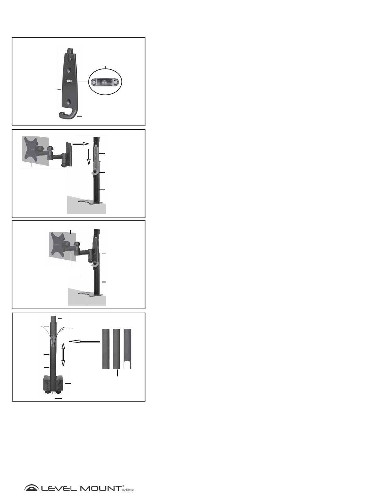
g
Niveau à bulle d’air
Assemblage/Installation
k
Moniteur
Platine
du bras
Figure 11
Support
d’écran
Bureau
Niveau à bulle d’air
intégré / Niveau
Cordon
Gestion
Figure 12
Niveau à bulle
Platine du bras
Cordon
Gestion
Support
pour bureau
Étape 4 – (Suite)
La platine du bras est munie d’un niveau à bulle intégré / niveau pour
garantir que l’écran plat est de niveau lorsqu’il est fixé au support
vertical. Le crochet d’enroulement du cordon situé dans la partie
inférieure de la platine du bras rassemble les cordons du moniteur qui
passent par la goulotte de protection du cordon comme indiqué en
Figure 11.
Soulevez l’écran plat fixé sur son support, plus haut que la platine du
bras, qui est fixée au support de bureau. Placez l’arrière du support du
moniteur sur la platine du bras et faites coulisser le support vers le bas
jusqu’à ce qu’il s’enclenche avec la platine du bras comme indiqué en
Figure 12.
Le support d’écran plat fixé à la platine du bras et au support de
bureau est montré en Figure 13.
Goulotte de
protection du
cordon
Goulotte de
protection du
cordon
Goulotte de
protection du
cordon
Moniteur
Support
pport
d’écran
pour bureau
Cordon
ran
Desk
es
Support
Équerre
Figure 13
Platine du
bras
Support
pour bureau
Figure 14
Goulotte de
protection du
cordon
Étape 5 – Fixation des goulottes de protection
d’enroulement des cordons
Pour organiser et cacher les cordons du moniteur, glissez la goulotte de protection
du cordon sur les cordons puis faites-la glisser vers le bas du support vertical
comme indiqué en Figure 14. Commencez par la goulotte ayant une forme
rectangulaire, laquelle s’ouvre dans la partie inférieure afin que les cordons
puissent être connectés à une prise. Installez la goulotte de protection du cordon
présentant une découpe en dernier, afin que les cordons puissent être reliés au
moniteur.
www.levelmount.com
19
©2011 Level Mount - Patents Pendin
1-888-229-1459
EU: +0044 844 567 2657
UK: 0844 567 2657
Page 20

Brauchen Sie Hilfe?
Nützliche Hinweise
Wenn Sie Fragen zur Montage Ihrer Tischhalterung haben, lesen Sie bitte die „Nützlichen Hinweise“, die Sie auf der oder
über die Produktdetailseite der Tischhalterung fi nden.
Wenden Sie sich an den Amazon-Kundendienst
Sollten Sie Fragen haben, können Sie sich auch an den Kundendienst von Amazon wenden, indem Sie die Hilfeseite der
jeweiligen Website aufrufen und dort am rechten Seitenrand auf „Kontakt“ klicken: www.amazon.com/help,
www.amazon.co.uk/help, www.amazon.de/hilfe, www.amazon.fr/aide und www.amazon.cn/help. In den USA können Sie
darüber hinaus auf der Produktdetailseite für die Tischhalterung unter „Click to Call“ die Anruffunktion verwenden.
Auf Montageanleitungen und „Nützliche Hinweise“ zugreifen
Sie können von der Produktdetailseite der Tischhalterung aus auf die Montageanleitungen und „Nützliche Hinweise“
zugreifen. Außerdem fi nden Sie Übersetzungen in folgende Sprachen auf den unten angegebenen Websites:
Englisch: Produktinformationen und Anleitungen in englischer Sprache fi nden Sie unter: www.amazon.co.uk/basics-
manuals
Français: Pour avoir des informations produit et des instructions en français, veuillez visiter ces pages: www.amazon.fr/
manuels-basics
Deutsch: Für Informationen und deutschsprachige Anweisungen besuchen Sie bitte www.amazon.de/basicsbedienungsanleitungen
Italiano: Per informazioni e istruzioni in italiano, si rimanda al sito www.amazon.co.uk/basics-manuals, www.amazon.fr/
manuels-basics or www. amazon.de/basics-bedienungsanleitungen
Español: Para consultar la información y las instrucciones del producto en español, visite www.amazon.co.uk/basicsmanuals, www.amazon.fr/manuels¬ o www.amazon.de/basics-bedienungsanleitungen
Nederlands: Basics www.amazon.de/basics-bedienungsanleitungen Nederlands: Voor productinformatie en instructies
in het Nederlands, ga naar www.amazon.co.uk/basics-manuals, www.amazon.fr/manuels-basics of
www.amazon.de/basics-bedienungsanleitungen
Polska: Aby uzyskać informacje i instrukcje po polsku, prosimy odwiedzić strony www.amazon.co.uk/basics-manuals,
www.amazon.fr/manuels-basics lub www.amazon.de/basics-bedienungsanleitungen
Ελληνικά: Για πληροφορίες για το προϊόν και οδηγίες στα ελληνικά παρακαλώ επισκεφθείτε τις παρακάτω ιστοσελίδες
www.amazon.co.uk/basics-manuals, www.amazon.fr/manuels-basics ή www.amazon.de/basics-bedienungsanleitungen
Português: Para informações do produto e instruções em português, favor visitar www.amazon.co.uk/basics-manuals,
www.amazon.fr/manuels-basics ou www.amazon.de/basics-bedienungsanleitungen
Dansk: Du kan fi nde produktoplysninger og anvisninger på dansk ved at besøge www.amazon.co.uk/basics-manuals,
www.amazon.fr/manuels-basics eller www.amazon.de/basics-bedienungsanleitungen
Magyar: A magyar nyelvű termékinformációkat és utasításokat megtalálhatja a következő oldalon: www.amazon.co.uk/
basics-manuals, www.amazon.fr/manuels-basics or www.amazon.de/basics-bedienungsanleitungen
Slovenščina: Za informacije o izdelku in navodila v slovenskem jeziku obiščite www.amazon.co.uk/basics-manuals, www.
amazon.fr/manuels-basics ali www.amazon.de/basics-bedienungsanleitungen
Български език: За информация за продукта и инструкции на български език, моля, посетете: www.amazon.co.uk/basics-
manuals, www.amazon.fr/manuels-basics или www.amazon.de/basics-bedienungsanleitungen
Eesti: Toote informatsiooni ja juhised leiate eesti keeles, kui külastate veebilehti: www.amazon.co.uk/basics-manuals,
www.amazon.fr/manuels-basics või www.amazon.de/basics-bedienungsanleitungen
Lietuvių k.: Dėl informacijos apie gaminį ir instrukcijų lietuvių k. apsilankykite www.amazon.co.uk/basics-manuals, www.
amazon.fr/manuels-basics arba www.amazon.de/basics-bedienungsanleitungen
Svenska: För att se produktinformation och instruktioner på svenska gå till www.amazon.co.uk/basics-manuals, www.
amazon.fr/manuels-basics eller www.amazon.de/basics-bedienungsanleitungen
Suomi: tuotetiedot ja ohjeet suomeksi löytyvät seuraavista osoitteista: www.amazon.co.uk/basics-manuals,
www.amazon.fr/manuels-basics tai www. amazon.de/basics-bedienungsanleitungen
Page 21
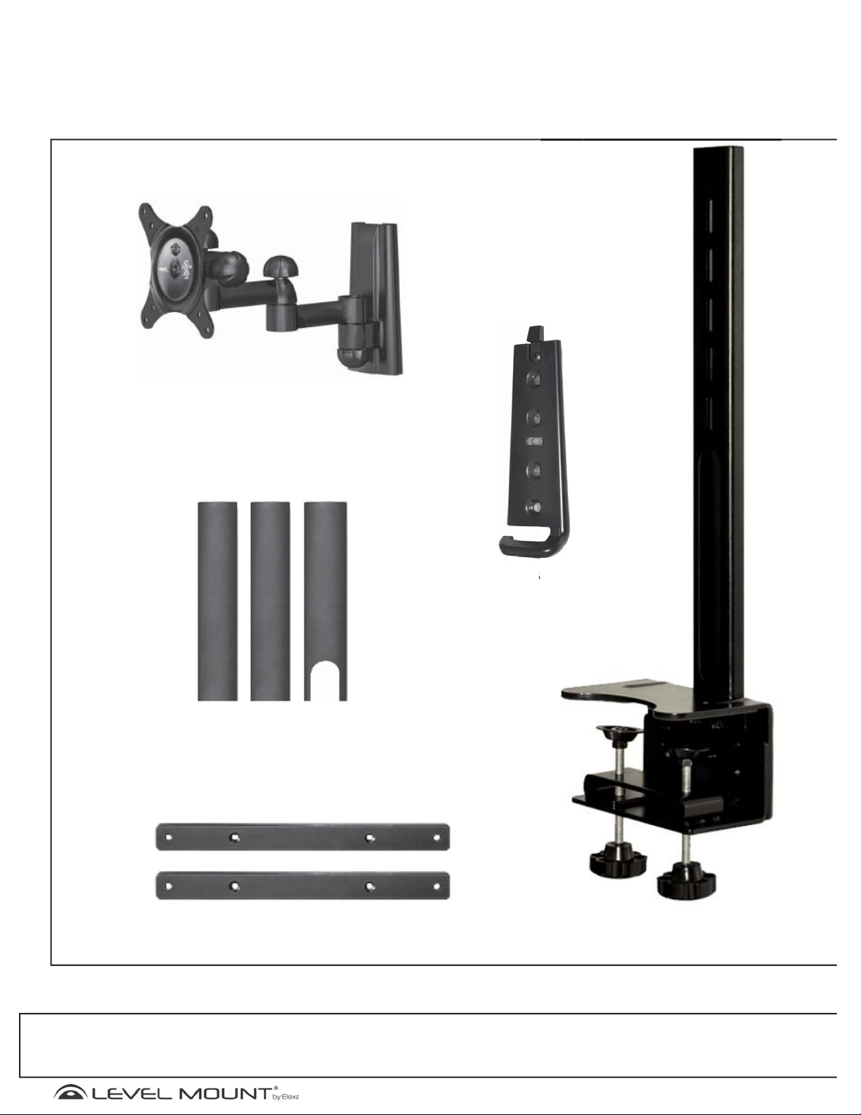
g
Was befindet sich im Paket?
e
Flachbildschirmhalt
Kabelabdeckung
Adapterarme
Befestigungsplatte
tigngsplatt
Tischarm
Nützliche Hinweise Wenn Sie Fragen zur Montage Ihrer Tischhalterung haben, lesen Sie bitte die „Nützlichen Hinweise“, die Sie auf der bzw. über die
Produktdetailseite der Tischhalterung finden. Wenden Sie sich an den Amazon-Kundendienst Wenn Sie Fragen haben, können Sie sich auch an den
Kundendienst von Amazon wenden, indem Sie die Hilfeseite der jeweiligen Website aufrufen und dort am rechten Seitenrand auf „Kontakt“ klicken: www.amazon.com/help, www.amazon.co.uk/help, www.amazon.de/hilfe, www.amazon.fr/aide und www.amazon.cn/help. In den USA können Sie darüber hinaus auf der
Produktdetailseite für die Tischhalterung unter „Click to Call“ die Anruffunktion verwenden.
21
©2011 Level Mount - Patents Pendin
www.levelmount.com
1-888-229-1459
EU: +0044 844 567 2657
UK: 0844 567 2657
Page 22
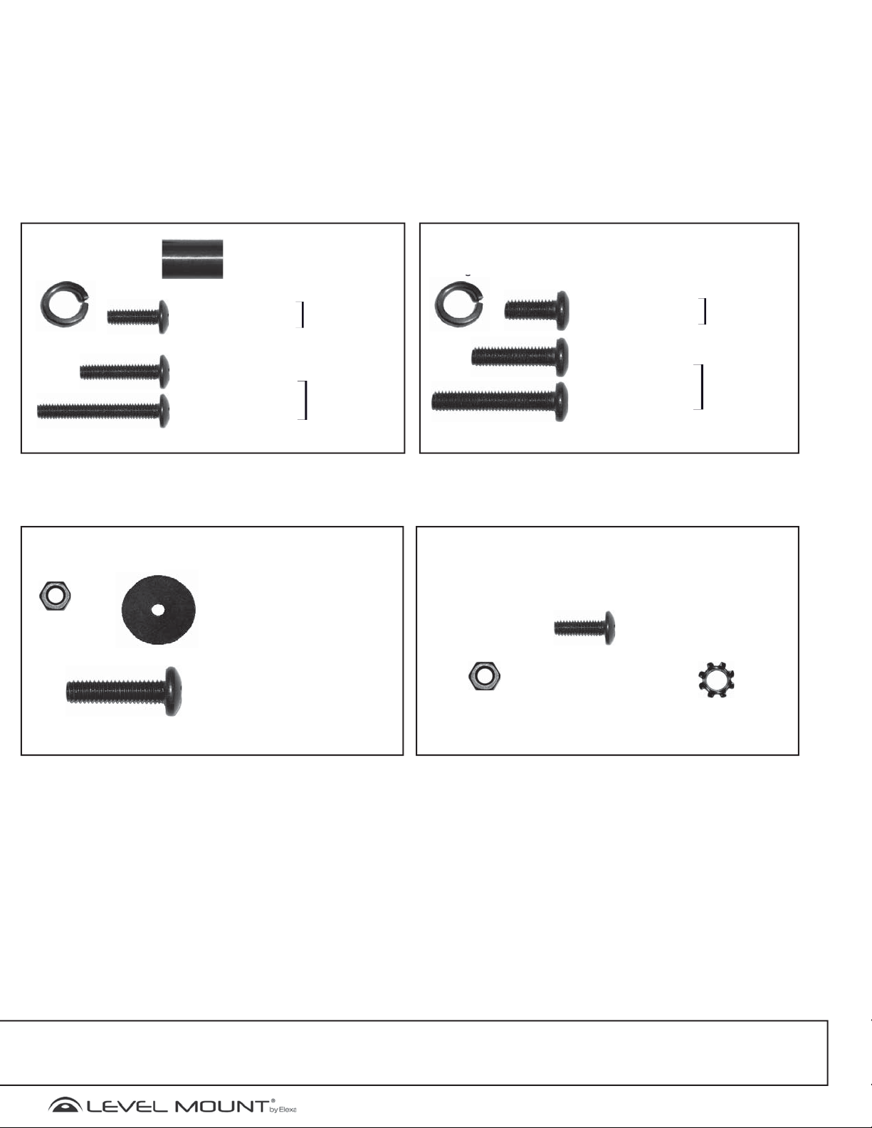
g
Was befindet sich im Paket?
g
Beutel 1
(4) M4
Unterlegscheibe
Beutel 3
(2) M6 Sechskantmutter
(4) Abstandhalter
15.9mm
(4) M4X12 mm
Phillips-Schraube
(4) M4X20 mm
Phillips-Schraube
(4) M4X30 mm
Phillips-Schraube
(2) Unterlegscheibe
16mmx6.3mmx1.2mm
Teile für Gerät
mit ebener
Rückseite
Teile für Gerät
mit Aussparung
auf der
Rückseite
Beutel 2
(4)M5
Unterlegscheibe
Beutel 4
(4) M5X12mm
Phillips-Schraube
(4) M5X20mm
Phillips-Schraube
(4) M5X30mm
Phillips-Schraube
Phillips-Schrauben und Zubehör
für die Adapterarme
(4) M4X12mm
Phillips-Schraube
Teile für Gerät
mit ebener
Rückseite
Teile für Gerät
mit Aussparung
auf der
Rückseite
(2) M6X22mm
Phillips-Schraube
Nützliche Hinweise Wenn Sie Fragen zur Montage Ihrer Tischhalterung haben, lesen Sie bitte die „Nützlichen Hinweise“, die Sie auf der bzw. über die
Produktdetailseite der Tischhalterung finden. Wenden Sie sich an den Amazon-Kundendienst Wenn Sie Fragen haben, können Sie sich auch an den
Kundendienst von Amazon wenden, indem Sie die Hilfeseite der jeweiligen Website aufrufen und dort am rechten Seitenrand auf „Kontakt“ klicken: www.amazon.com/help, www.amazon.co.uk/help, www.amazon.de/hilfe, www.amazon.fr/aide und www.amazon.cn/help. In den USA können Sie darüber hinaus auf der
Produktdetailseite für die Tischhalterung unter „Click to Call“ die Anruffunktion verwenden.
(4) M4 Sechskantmutter
22
(4) M4 Sicherungsscheibe
www.levelmount.com
1-888-229-1459
EU: +0044 844 567 2657
©2011 Level Mount - Patents Pendin
UK: 0844 567 2657
Page 23
g
Erste Schritte
VORSICHT!
!
Diese Tischhalterung wurde speziell zur Befestigung von Flachbildschirmen mit
einer Bildschirmdiagonalen von 25,4 cm – 76,2 cm (10 – 30 Zoll) und einem
Gewicht von höchstens 16 kg entwickelt. Die Verwendung dieses Produkts
für einen Flachbildschirm, dessen Gewicht oder Abmessungen die genannten
Vorgaben überschreiten, kann zu schweren Verletzungen, Schäden am Gerät und
sonstigen Sachschäden führen.
ACHTUNG:
1. Beginnen Sie erst mit der Montage der Tischhalterung, wenn Sie die Anleitung und die in diesen
Montageanweisungen enthaltenen Warnhinweise gelesen und verstanden haben. Wenn Sie die
Anleitung nicht sorgfältig lesen, vollständig verstehen und einhalten, kann dies zu schwerwiegenden
Verletzungen und Schäden am Gerät und an den baulichen Anlagen führen. Es liegt in der
Verantwortung desjenigen, der die Montage durchführt, sicherzustellen, dass alle Bestandteile nach
der bereitgestellten Anleitung ordnungsgemäß zusammengesetzt und montiert wurden.
2. Sollten Sie Fragen haben, die in diesen Montageanweisungen nicht behandelt werden, möchten
wir Sie auf die häufig gestellten Fragen im Abschnitt „Nützliche Hinweise“ der Detailseite für die
Tischhalterung verweisen oder Sie bitten, sich auf die im Abschnitt „Hilfe“ oben beschriebene Art
und Weise mit uns in Verbindung zu setzen. Falls Sie sich hinsichtlich eines in dieser Anleitung
beschriebenen Schritts unsicher sind oder nicht wissen, ob Sie in der Lage sind, die Tischhalterung
sicher anzubringen, sollten Sie eine kompetente Fachkraft hinzuziehen.
3. Diese Tischhalterung enthält Kleinteile, die beim Verschlucken eine Gefahr darstellen. Daher sollten
Sie sie von Kindern fernhalten.
4. Die Tischhalterung darf unter keinen Umständen im Freien angebracht werden. Wird dieses Produkt
im Freien verwendet, könnte dies zu Fehlfunktionen und schwerwiegenden Verletzungen oder
Schäden am Gerät oder an den baulichen Anlagen führen.
5. Die Befestigung der Tischhalterung an einer Tischplatte muss gemäß dieser Anleitung vorgenommen
werden. Verwenden Sie die Tischhalterung nur für die in dieser Anleitung genannten Geräte.
6. Überprüfen Sie, dass alle Schrauben fest angezogen sind, bevor Sie die Tischhalterung mit dem
vollen Gewicht des Flachbildschirms belasten. Ziehen Sie die Schrauben fest an, aber überziehen Sie
sie nicht. Drehen Sie die Schraube nicht mehr weiter, sobald sie bündig zum Flachbildschirm ist und
der Schraubendreher sich schwerer drehen lässt und schließlich keine weitere Drehung mehr möglich
ist. Andernfalls laufen Sie Gefahr, die Schraube zu überziehen. Ein Überziehen von Schrauben könnte
zu Schäden an der Tischhalterung führen und ihre Tragfähigkeit enorm verringern. Möglicherweise ist
ein regelmäßiges Nachziehen der Schrauben notwendig.
7. Die Schrauben sollten problemlos und vollständig in die Montagelöcher des Flachbildschirms
eingeschraubt werden. Sollten sich die bereitgestellten Schrauben nicht für das
Tischhalterungssystem eignen, darf der Monteur keinesfalls Löcher in den Flachbildschirm oder in die
Bestandteile der Tischhalterung bohren. Durch den Einsatz von Schrauben falscher Größe kann der
Flachbildschirm beschädigt werden.
8. Heben Sie nicht mehr Gewicht als Sie handhaben können. Wenn nötig, sollten mindestens zwei
Personen den Flachbildschirm anheben und auf der Tischhalterung platzieren
Nützliche Hinweise Wenn Sie Fragen zur Montage Ihrer Tischhalterung haben, lesen Sie bitte die „Nützlichen Hinweise“, die Sie auf der bzw. über die
Produktdetailseite der Tischhalterung finden. Wenden Sie sich an den Amazon-Kundendienst Wenn Sie Fragen haben, können Sie sich auch an den
Kundendienst von Amazon wenden, indem Sie die Hilfeseite der jeweiligen Website aufrufen und dort am rechten Seitenrand auf „Kontakt“ klicken: www.amazon.com/help, www.amazon.co.uk/help, www.amazon.de/hilfe, www.amazon.fr/aide und www.amazon.cn/help. In den USA können Sie darüber hinaus auf der
Produktdetailseite für die Tischhalterung unter „Click to Call“ die Anruffunktion verwenden.
23
©2011 Level Mount - Patents Pendin
www.levelmount.com
1-888-229-1459
EU: +0044 844 567 2657
UK: 0844 567 2657
Page 24
g
Erste Schritte
9. Überprüfen Sie vor der Montage, dass alle in diesen Montageanweisungen aufgeführten Teile der
Tischhalterung vollständig vorhanden und unbeschädigt sind. Verwenden Sie niemals beschädigte Teile
und versuchen Sie bitte nicht, die Tischhalterung anzubringen, sofern Sie nicht über alle notwendigen Teile
verfügen.
10. Es liegt in der Verantwortung desjenigen, der die Montage durchführt, die für die Montage
geeignete Stelle und die tragende Fläche auszuwählen, an der die Tischhalterung angebracht wird,
und sicherzustellen, dass die Tischhalterung ordnungsgemäß an der Tischplatte befestigt ist. Darüber
hinaus liegt es in der Verantwortung desjenigen, der die Montage durchführt, sicherzustellen, dass der
Flachbildschirm ordnungsgemäß und sicher und nur unter Verwendung der beigefügten Befestigungsmittel
und Bestandteile an der Tischhalterung befestigt ist, und sicherzustellen, dass die Schrauben und
Anschlusskabel nicht mit Drähten, Rohren oder Metallteilen in Berührung kommen (dies könnte diese Teile
beschädigen oder einen Stromschlag bewirken).
11. Amazon.com, Inc. und seine Tochterunternehmen (zusammen „Amazon“) haben alle notwendigen
Maßnahmen getroff en, damit die vorliegenden Montageanweisungen genau und vollständig sind. Amazon
erhebt jedoch nicht den Anspruch, dass die hier enthaltenen Informationen alle Details, Bedingungen
oder Variationen abdecken oder alle denkbaren Eventualitäten in Verbindung mit der Montage, dem
Zusammensetzen oder der Verwendung dieses Produkts behandeln. Amazon gibt keine Zusicherung oder
Garantie, sei es ausdrücklich oder stillschweigend, hinsichtlich der Genauigkeit, Vollständigkeit oder der
Hinlänglichkeit der in diesem Dokument enthaltenen Informationen. Für Schäden oder Verletzungen, die aus
einer unsachgemäßen Montage, Zusammensetzung, Anbringung oder Verwendung resultieren, übernimmt
Amazon keine Verantwortung.
Nützliche Hinweise Wenn Sie Fragen zu Ihrer Tischhalterung haben, lesen Sie bitte die „Nützlichen
Hinweise“, die Sie auf der bzw. über die Produktdetailseite der Tischhalterung fi nden. Wenden Sie sich
an den Amazon-Kundendienst Sollten Sie Fragen haben, können Sie sich auch an den Kundendienst von
Amazon wenden, indem Sie die Hilfeseite der jeweiligen Website aufrufen und dort am rechten Seitenrand
auf „Kontakt“ klicken: www.amazon.com/help, www.amazon.co.uk/help, www.amazon.de/hilfe, www.
amazon.fr/aide und www.amazon.cn/help. In den USA können Sie darüber hinaus auf der Produktdetailseite
für die Tischhalterung unter „Click to Call“ die Anruff unktion verwenden.
Benötigte Werkzeuge
Mitgeliefert:
Integrierte
Wasserwaage
Nicht mitgeliefert
PhillipsSchraubendreher
Nützliche Hinweise Wenn Sie Fragen zur Montage Ihrer Tischhalterung haben, lesen Sie bitte die „Nützlichen Hinweise“, die Sie auf der bzw. über die
Produktdetailseite der Tischhalterung finden. Wenden Sie sich an den Amazon-Kundendienst Wenn Sie Fragen haben, können Sie sich auch an den
Kundendienst von Amazon wenden, indem Sie die Hilfeseite der jeweiligen Website aufrufen und dort am rechten Seitenrand auf „Kontakt“ klicken: www.amazon.com/help, www.amazon.co.uk/help, www.amazon.de/hilfe, www.amazon.fr/aide und www.amazon.cn/help. In den USA können Sie darüber hinaus auf der
Produktdetailseite für die Tischhalterung unter „Click to Call“ die Anruffunktion verwenden.
24
©2011 Level Mount - Patents Pendin
www.levelmount.com
1-888-229-1459
EU: +0044 844 567 2657
UK: 0844 567 2657
Page 25
g
Zusammensetzen/Anbringen
h
Abbildung 1
Bildschirm
mit ebener
Abbildung 2
Flachbildschirmhalterung
Adapterarm
M4 Schraube
Phillips-
Schraubendreher
Bildschirm mit
Aussparung auf
Sicherungsscheibe
M4
M4
4
Sechskantmutter
ec
Schritt 1 – Auswahl der passenden Teile je nach Rückseite
des Flachbildschirms
Bevor Sie mit dem Anbringen beginnen, stellen Sie fest, ob die Rückseite Ihres
Flachbildschirms eben ist oder eine Aussparung aufweist, wie in Abbildung 1
gezeigt. Weist die Rückseite Ihres Flachbildschirms eine Aussparung auf, müssen
Sie möglicherweise die in Abbildung 4 oder 6 gezeigten Abstandhalter (Beutel 1)
verwenden. Mit dem Abstandhalter wird die Aussparung auf der Geräterückseite
überbrückt, so dass die Halterung für den Flachbildschirm vollkommen bündig mit
der Geräterückseite ist und auf dieser aufliegt.
Schritt 2 – Anbringen der Adapterarme (falls erforderlich)
Falls die Löcher in der Flachbildschirmhalterung nicht mit den Löchern an der
Geräterückseite übereinstimmen, bohren Sie bitte keine neuen Löcher. Befolgen Sie
vielmehr diese Anleitung zum Anbringen der Adapterarme. Andernfalls lesen Sie
bitte bei Schritt 3 weiter.
Hinweis: Die Adapterarme können für Flachbildschirme mit einer VESA-
Lochanordnung mit einem Abstand von 200 mm x 100 mm verwendet
werden. Den VESA-Lochabstand Ihres Flachbildschirms entnehmen Sie
bitte dem Handbuch/den Kennzeichnungen des Geräts. .
Schritt 2a – Anbringen der Adapterarme an der
Flachbildschirmhalterung
Befestigen Sie den ersten Satz Adapterarme an der Halterung des Flachbildschirms
und verwenden Sie dazu die in Abbildung 2 gezeigten Teile:
• Phillips-Schraube M4 (Beutel 4)
• Adapterarme
• Flachbildschirmhalterung
• Sicherungsscheiben M4 (Beutel 4)
• Sechskantmutter M4 (Beutel 4)
Passen Sie die Position der in Abbildung 2 gezeigten Schrauben so an, dass die
Adapterarme bewegt und auf die Löcher an der Bildschirmrückseite ausgerichtet
werden können.
Flachbildschirm
Abbildung 3
Schritt 2b – Abschließende Montage der Adapterarme
Befestigen Sie beide Adapterarme auf dieselbe Weise. Den fertigen Zustand zeigt
das Foto in Abbildung 3.
Adapterarm
Bildschirmhalterun
Nützliche Hinweise Wenn Sie Fragen zur Montage Ihrer Tischhalterung haben, lesen Sie bitte die „Nützlichen Hinweise“, die Sie auf der bzw. über die
Produktdetailseite der Tischhalterung finden. Wenden Sie sich an den Amazon-Kundendienst Wenn Sie Fragen haben, können Sie sich auch an den
Kundendienst von Amazon wenden, indem Sie die Hilfeseite der jeweiligen Website aufrufen und dort am rechten Seitenrand auf „Kontakt“ klicken: www.amazon.com/help, www.amazon.co.uk/help, www.amazon.de/hilfe, www.amazon.fr/aide und www.amazon.cn/help. In den USA können Sie darüber hinaus auf der
Produktdetailseite für die Tischhalterung unter „Click to Call“ die Anruffunktion verwenden.
25
©2011 Level Mount - Patents Pendin
www.levelmount.com
1-888-229-1459
EU: +0044 844 567 2657
UK: 0844 567 2657
Page 26
g
Zusammensetzen/Anbringen
Bildschirm mit
ebener Rückseite
Abstandhalter nur für Bildschirme mit einer
Aussparung in der Rückseite verwenden
Abbildung 4
M4/M5
Unterlegscheibe
Abstandhalter
Adapterarme
Bildschirmhalterung
M4/M5
Schraube
Phillips-
Schraubendreher
Abbildung 5
Bildschirm mit ebener Rückseite
Adapterarme
M4/M5
Schraube
Bildschirmhalterung
Schritt 2c – Anbringen der Adapterarme an der Rückseite
des Flachbildschirms
In diesem Paket sind (in Beutel 1 und 2) Schrauben unterschiedlicher Länge
enthalten. Bitte verwenden Sie die Schraube der für Ihren Flachbildschirm
geeigneten Länge.
• Schraube M4 (Beutel 1) oder Schraube M5 (Beutel 2)
• Unterlegscheibe M4 (Beutel 1) oder Unterlegscheibe M5 (Beutel 2)
Möglicherweise ist eine weitere Unterlegscheibe notwendig, um zu
verhindern, dass der Schraubenkopf in der Geräterückseite versinkt.
• Adapterarm
• Abstandhalter (Beutel 1) Nur bei Flachbildschirmen erforderlich, deren
Rückseite eine Aussparung aufweist.
Um die Adapterarme an der Rückseite des Flachbildschirms anzubringen,
befestigen Sie die Adapterarme mithilfe der oben angegebenen Teile waagerecht
an der Bildschirmhalterung. Führen Sie die 2 Schrauben für jeden Arm durch die
Löcher der Adapterarme und schrauben Sie die Schrauben vorsichtig in die Löcher
in der Rückseite des Flachbildschirms. Sollten Sie dabei einen Widerstand spüren,
entfernen Sie die Schraube unverzüglich und wählen Sie eine Schraube korrekter
Größe, die sicher und genau passt.
Schrauben Sie die Schrauben wie in Abbildung 5 gezeigt in die Geräterückseite und
ziehen Sie sie fest an. Lesen Sie dann bei Schritt 4 weiter.
Vorsicht: Ziehen Sie die Schrauben nur an, bis sie fest eingeschraubt sind –
überziehen Sie sie nicht.
Bildschirm mit
ebener Rückseite
Bildschirmhalterung
Abbildung 6
M4/M5
Unterlegscheibe
Abstandhalter
M4/M5
Schraube
Phillips-
Schraubendreher
Abstandhalter nur für Bildschirme mit einer
Aussparung in der Rückseite verwenden
Bildschirm mit
ebener Rückseite
M4/M5
Schraube
Abbildung 7
Bildschirmhalterung
Schritt 3 – Anbringen der Flachbildschirmhalterung an der
Rückseite des Flachbildschirms
In diesem Paket sind (in Beutel 1 und 2) Schrauben unterschiedlicher Länge enthalten.
Bitte verwenden Sie die Schraube in der für Ihren Flachbildschirm geeigneten Länge.
• Schraube M4 (Beutel 1) oder Schraube M5 (Beutel 2)
• Unterlegscheibe M4 (Beutel 1) oder Unterlegscheibe M5 (Beutel 2)
• Möglicherweise ist eine weitere Unterlegscheibe notwendig, um zu
verhindern, dass der Schraubenkopf in der Geräterückseite versinkt.
• Adapterarm
• Abstandhalter (Beutel 1) Nur bei Flachbildschirmen erforderlich, deren
Rückseite eine Aussparung aufweist.
Um die Flachbildschirmhalterung an der Rückseite des Flachbildschirms anzubringen,
führen Sie bitte 4 Schrauben durch die Löcher der Flachbildschirmhalterung und
schrauben diese vorsichtig in die Löcher in der Rückseite des Flachbildschirms.
Sollten Sie dabei einen Widerstand spüren, entfernen Sie die Schraube unverzüglich
und wählen Sie eine Schraube korrekter Größe, die sicher und genau passt.
Schrauben Sie die Schrauben, wie in Abbildung 7 gezeigt, in die Geräterückseite und
ziehen Sie sie fest an.
Vorsicht: Ziehen Sie die Schrauben nur an, bis sie fest eingeschraubt sind –
überziehen Sie sie nicht.
Nützliche Hinweise Wenn Sie Fragen zur Montage Ihrer Tischhalterung haben, lesen Sie bitte die „Nützlichen Hinweise“, die Sie auf der bzw. über die
Produktdetailseite der Tischhalterung finden. Wenden Sie sich an den Amazon-Kundendienst Wenn Sie Fragen haben, können Sie sich auch an den
Kundendienst von Amazon wenden, indem Sie die Hilfeseite der jeweiligen Website aufrufen und dort am rechten Seitenrand auf „Kontakt“ klicken: www.amazon.com/help, www.amazon.co.uk/help, www.amazon.de/hilfe, www.amazon.fr/aide und www.amazon.cn/help. In den USA können Sie darüber hinaus auf der
Produktdetailseite für die Tischhalterung unter „Click to Call“ die Anruffunktion verwenden.
26
©2011 Level Mount - Patents Pendin
www.levelmount.com
1-888-229-1459
EU: +0044 844 567 2657
UK: 0844 567 2657
Page 27
g
Zusammensetzen/Anbringen
sk
Abbildung 8
Tischarm
Dünne
Tischplatte
Schrauben
L-Winkel
Sicherungsschrauben
Abbildung 9
Tischarm
Tischplatte
Sicherungsschrauben
Befestigungsplatte
M6
Schraube
Tischarm
Dicke
Tischplatte
für den
Sicherungsschrauben
Tischarm
Tischplatte
Sicherungsschrauben
Abbildung 10
Unterlegscheib
16mmx6.3mmx1.2mm
Sc
Schrauben
für den
L-Winkel
Schritt 4 – Befestigen des Tischarms und der
Befestigungsplatte am (Schreib-)Tisch
Platzieren Sie den L-Winkel des Tischarms, wie in Abbildung 8 gezeigt, auf der
Tischplatte. Drehen Sie die Sicherungsschrauben in Uhrzeigerrichtung, bis sie eng
an der Tischplatte anliegen, wie in Abbildung 9 gezeigt.
In den meisten Fällen befinden sich die Schrauben des L-Winkels bereits in
der richtigen Position. In einigen Fällen muss der L-Winkel aufgrund der Dicke
der Tischplatte angepasst werden. Um die Position der Schrauben im L-Winkel
anzupassen, schrauben Sie diese Schrauben einfach heraus und passen Sie den
Winkel der Tischplatte an. Ziehen Sie die Schrauben danach wieder fest an.
Vorsicht: Der L-Winkel passt nur, wenn der Rand der Tischplatte zwischen 1,27
und 6,35 Zentimeter dick und mindestens
5,08 Zentimeter tief ist. Wenn der Rand der Tischplatte nicht aus massivem
Holz besteht, müssen Sie sicherstellen, dass er das Gewicht der
Halterung und des Monitors/Bildschirms tragen kann.
Befestigen Sie, wie in Abbildung 10 gezeigt, die Befestigungsplatte mithilfe der
Löcher im Tischarm in der gewünschten Höhe – abhängig von der Größe
des Flachbildschirms. Verwenden Sie dazu folgende Teile aus Beutel 3:
• Schrauben M6 (Beutel 3)
• Befestigungsplatte
• Tischarm
• Unterlegscheibe 16 mm x 6,3 mm x 1,2 mm (Beutel 3)
• Sechskantmutter M6 (Beutel 3)
Mithilfe der in die Befestigungsplatte integrierten Wasserwaage können Sie
sicherstellen, dass der Flachbildschirm waagerecht am Tischarm angebracht
ist. Mithilfe des Kabelhaltehakens (in Abbildung 11 gezeigt) unten an der
Befestigungsplatte lassen sich die Kabel des Flachbildschirms sammeln, um sie
durch die Kabelabdeckung zu führen.
Heben Sie den Flachbildschirm mit der daran befestigten Flachbildschirmhalterung
auf eine Höhe oberhalb der am Tischarm befestigten Befestigungsplatte
an. Platzieren Sie die Rückseite der Flachbildschirmhalterung oberhalb der
Befestigungsplatte und schieben Sie die Flachbildschirmhalterung nach unten, bis
sie, wie in Abbildung 12 gezeigt, in der Befestigungsplatte einrastet.
Wenn die Flachbildschirmhalterung an der Befestigungsplatte und diese am
Tischarm befestigt ist, sieht die Tischhalterung so aus wie in Abbildung 13
Phillips-
Schraubendreher
e
Desk
Sechskantmutter
M6
Tischarm
Abbildung 11
Integrierte Wasserwaage
Befestigungsplatte
Kabelhaltehaken
Nützliche Hinweise Wenn Sie Fragen zur Montage Ihrer Tischhalterung haben, lesen Sie bitte die „Nützlichen Hinweise“, die Sie auf der bzw. über die
Produktdetailseite der Tischhalterung finden. Wenden Sie sich an den Amazon-Kundendienst Wenn Sie Fragen haben, können Sie sich auch an den
Kundendienst von Amazon wenden, indem Sie die Hilfeseite der jeweiligen Website aufrufen und dort am rechten Seitenrand auf „Kontakt“ klicken: www.amazon.com/help, www.amazon.co.uk/help, www.amazon.de/hilfe, www.amazon.fr/aide und www.amazon.cn/help. In den USA können Sie darüber hinaus auf der
Produktdetailseite für die Tischhalterung unter „Click to Call“ die Anruffunktion verwenden.
27
©2011 Level Mount - Patents Pendin
www.levelmount.com
1-888-229-1459
EU: +0044 844 567 2657
UK: 0844 567 2657
Page 28
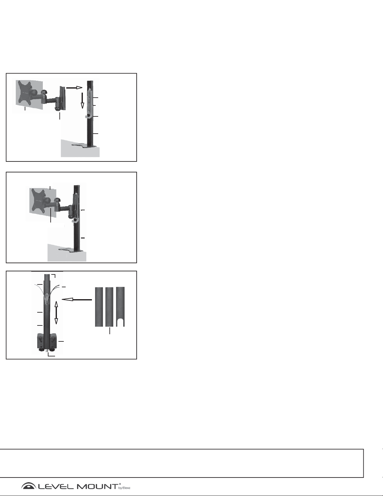
g
Zusammensetzen/Anbringen
esk
n
Abbildung 12
Wasserwaage
Befestigungsplatt
Bildschirm
Bildschirmhalterun
Tischplatt
Kabelhaltehaken
Tischarm
Bildschirm
Bildschirmhalterun
Kabelabdeckung
Kabelabdeckung
Kabelabdeckung
alteru
D
Desk
Abbildung 13
Tischarm
L-Winkel
Kabel
Befestigungsplatt
Tischarm
Abbildung 14
Kabelabdeckung
Schritt 5 – Anbringen der Abdeckungen für die
Kabelführung
Um die Kabel des Flachbildschirms zu ordnen und zu verdecken, schieben Sie, wie
in Abbildung 14 gezeigt, die Kabelabdeckung über die Kabel und an der Rückseite
des Tischarms nach unten. Beginnen Sie mit den rechteckigen Kabelabdeckungen,
die am unteren Ende offen sind, so dass Sie die Stecker in eine Steckdose stecken
können. Bringen Sie die U-förmig ausgeschnittene Kabelabdeckung zuletzt an, so
dass Sie die Kabel am Flachbildschirm anschließen können.
Nützliche Hinweise Wenn Sie Fragen zur Montage Ihrer Tischhalterung haben, lesen Sie bitte die „Nützlichen Hinweise“, die Sie auf der bzw. über die
Produktdetailseite der Tischhalterung finden. Wenden Sie sich an den Amazon-Kundendienst Wenn Sie Fragen haben, können Sie sich auch an den
Kundendienst von Amazon wenden, indem Sie die Hilfeseite der jeweiligen Website aufrufen und dort am rechten Seitenrand auf „Kontakt“ klicken: www.amazon.com/help, www.amazon.co.uk/help, www.amazon.de/hilfe, www.amazon.fr/aide und www.amazon.cn/help. In den USA können Sie darüber hinaus auf der
Produktdetailseite für die Tischhalterung unter „Click to Call“ die Anruffunktion verwenden.
28
©2011 Level Mount - Patents Pendin
www.levelmount.com
1-888-229-1459
EU: +0044 844 567 2657
UK: 0844 567 2657
Page 29

© 2011. All rights reserved. Patents Pending. Level Mount is a trademark of Elexa Consumer
Products, Inc. All other trademarks are the property of their respective owners.
© 2011. Tous droits réservés. Brevets en instance Level Mount est une marque déposée de
Elexa Consumer Products, Inc. Toutes les autres marques de commerce appartiennent à leurs proprié-
taires ou détenteurs respectifs.
© 2011. Todos los derechos reservados. Pendiente de patente. Level Mount es una marca registrada
de Elexa Consumer Products, Inc. El resto de marcas registradas pertenecen a sus correspondi-
entes dueños.
 Loading...