


DC65ADLP
Installation Instructions
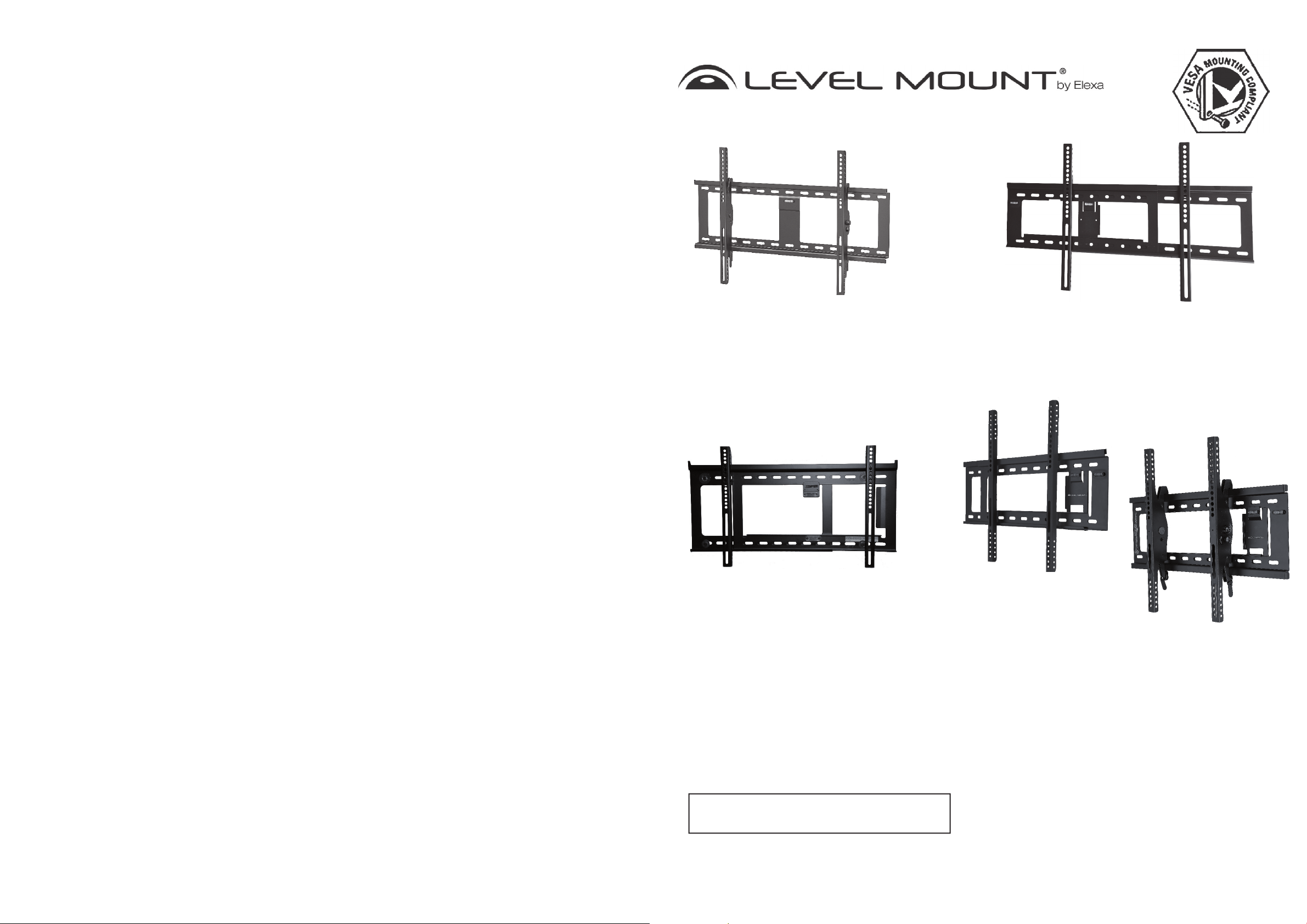
Extra Large Tilt TV Wall Mount fi ts
37”- 85” (939,8 mm - 2159 mm)
Flat Panel Displays - up to 200 lb
(90kg) capacity - Black (HE800T.
HE885T)
Adjustable Fixed TV Wall Mount fi ts
26”-85” (660,4 mm - 2159 mm)
Flat Panel Displays - up to 200 lb
(90kg) capacity - Black (DC65ADLP,
LM65ADLP & ELPFW-07)
Adjustable Fixed TV Wall Mount
fi ts 26”- 85” (660,4 mm - 2159 mm)
Flat Panel Displays - up to 200 lb
(90kg) capacity - Black (NTPFW,
LMPFW85)
Adjustable Fixed or Tilt TV Wall
Mount fi ts 26”-85” (660,4 mm -
2159 mm) Flat Panel Displays
- up to 200 lb (90kg) capacity Black (HETWF)
Please read these Installation Instructions entirely, including the Warnings, before you start
the installation and assembly of the TV Wall Mount.
Instructions en Francais, Page 10
Instrucciones en Español, Página 18
Need Help?
Helpful Hints
If you have installation questions about your TV Wall Mount, please go to www.levelmount.com to view
product tutorials.
Contacting Level Mount Customer Service
If you have questions, our trained Customer Service Department is happy to assist you 24 hours a day,
7 days a week, every day of the year. Contact Level Mount Customer Service as follows:
• In the United States dial: 1-888-229-1459
• In Europe dial: +0044 844 567 2657
• In the United Kingdom dial: 0844 567 2657
• E-mail Level Mount at www.customersupport@elexausa.com
DO NOT RETURN THIS PRODUCT TO THE STORE OR WEB SITE FROM WHICH IT WAS
PURCHASED
If you believe the product is defective, has a missing or broken part or are having diffi culty with
assembly, please contact Level Mount directly 24 hours a day, 7 days a week, 365 days a year as listed
above, for a quick and effi cient solution to your problem.
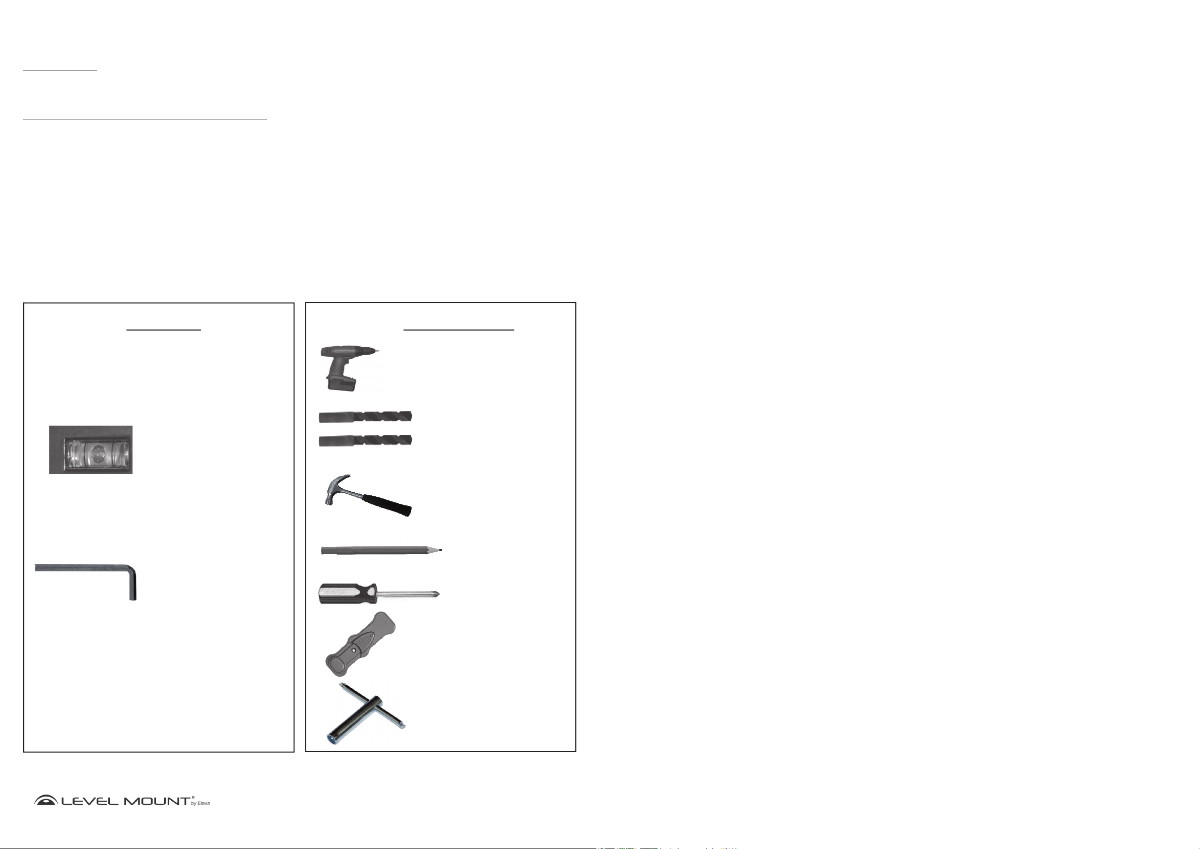
Tools Required
Included
Built-in Bubble Level
Spirit Level
Allen Wrench
(HETWF, HE800T,
HE885T)
Not Included
Drill Bit 4mm
Drill Bit Masonry 12mm
Hammer
Pencil
Phillips
Screwdriver
Stud Finder
Hex Wrench
www.levelmount.com
2
©2011 Level Mount - Patents Pending
1-888-229-1459
EU: +0044 844 567 2657
UK: 0844 567 2657
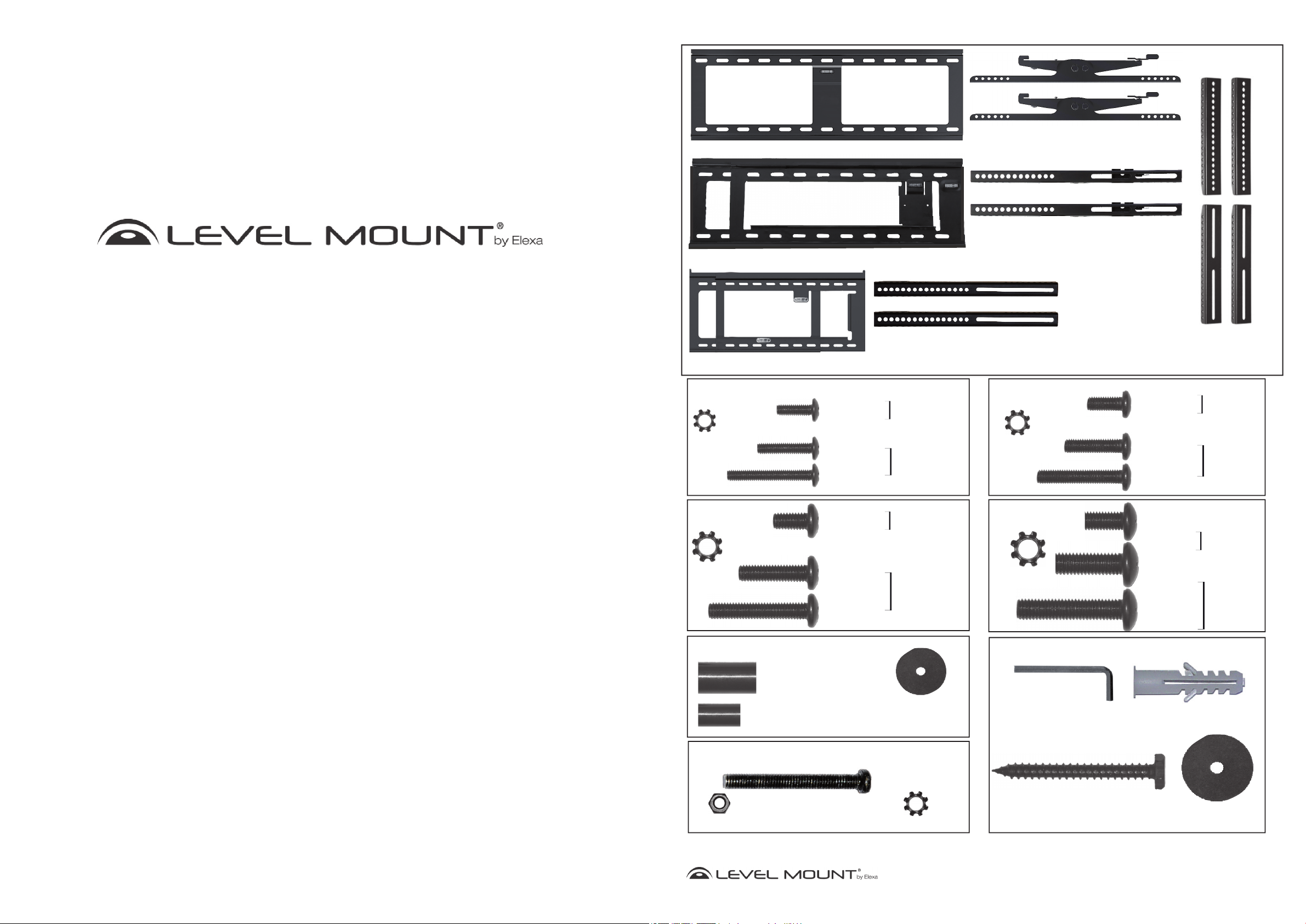
What’s in the box?
Wall Plate - HE800T, HE885T
Wall Plate - HETWF, NTPFW, LMPFW85
Tilt Arms - HETWF, HE800T, HE885T
Fixed Arms - HETWF, NTPFW, LMPFW85
© 2012. All rights reserved. Patents Pending. Level Mount is a trademark of Elexa Consumer
Products, Inc. All other trademarks are the property of their respective owners.
© 2012. Tous droits réservés. Brevets en instance Level Mount est une marque déposée de
Elexa Consumer Products, Inc. Toutes les autres marques de commerce appartiennent à leurs proprié-
taires ou détenteurs respectifs.
© 2012. Todos los derechos reservados. Pendiente de patente. Level Mount es una marca registrada
de Elexa Consumer Products, Inc. El resto de marcas registradas pertenecen a sus correspondi-
entes dueños.
Wall Plate - 65ADLP, ELPFW-07
Bag 1
(4) M4 Lock Washer
Bag 3
(4) M6 Lock Washer
(4) M4 x 12mm
Phillips Bolt
(4) M4 x 20mm
Phillips Bolt
(4) M4 x 30mm
Phillips Bolt
(4) M6 x 12mm
Phillips Bolt
(4) M6 x 24mm
Phillips Bolt
(4) M6 x 35mm
Phillips Bolt
Bag 5
Fixed Arms - 65ADLP, ELPFW-07
Bag 2
Flat Back
TV Hardware
Recessed
Back
TV Hardware
Flat Back
TV Hardware
Recessed
Back
TV Hardware
(4)M5 Lock Washer
Bag 4
(4) M8 Lock Washer
Bag 6
(4) M5 x 12mm
Phillips Bolt
(4) M5 x 20mm
Phillips bolt
(4) M5 x 30mm
Phillips Bolt
(4) M8 x 16mm
Phillips Bolt
(4) M8 x 25mm
Phillips Bolt
(4) M8 x 40mm
Phillips Bolt
Extension Arms
Flat Back
TV Hardware
Recessed
Back
TV Hardware
Flat Back
TV Hardware
Recessed
Back
TV Hardware
Bag 7
(8) M5 Nut
(4) Spacer
Ø17.5 x Ø8.3 x 22.5 mm
(4) Spacer
Ø12.5 x Ø5.5 x 16.5 mm
Phillips Bolt
(4) Washer
Ø20 x Ø5.5 x 1.0 mm
(8) M5 x 40mm
(8) M5 Lock Washer
(1) Allen Wrench Key
(HETWF, HE800T,
HE885T)
(6) Hex Wood Screw
Ø6.3 x 75mm
3
(6) Concrete Anchors
Ø12 x 60 mm
28mm x Ø8mm x 1.5mm
©2011 Level Mount - Patents Pending
(6) Washer
www.levelmount.com
EU: +0044 844 567 2657
UK: 0844 567 2657
1-888-229-1459
Getting Started
Placa de soporte
Pegado a la
Pared
Brazos fijos o
en la pared
posterior de la televisión
Brazos
Brazos
Placa de
soporte
TVTV
a
ave Alle
n
Allen
o
o
o
!
These TV Wall Mounts were designed specifically to hold TVs with a maximum weight of up to 200
lbs (90kg) and with the following dimensions: 37” - 85” (939,8 mm - 2159 mm) HE800T, HE885T
and 26” - 85” (660,4 mm - 2159 mm) NTPFW, LMPFW85, DC65ADLP, LM65ADLP, ELPFW-07,
HETWF. Using this product with a TV heavier than the maximum weight, or that exceeds these
dimensions, may result in serious personal injury and damage to equipment and property.
1. Do not begin the installation of the TV Wall Mount until you have read and understood the instructions and warnings
contained in these Installation Instructions. Failure to read, thoroughly understand and follow the instructions can
result in serious personal injury and damage to equipment and property. It is the installer’s responsibility to make
sure all components are properly assembled and installed using the instructions provided.
2. If you have questions that do not appear to be covered in these Installation Instructions, please refer to the “Helpful
Hints” section of the detail page for the TV Wall Mount or contact us as described under the “Need Help” section.
If you are at all unsure about any step in these instructions or your ability to install the TV Wall Mount safely and
securely, you should seek professional help from a qualified contractor.
3. This TV Wall Mount contains small items that could be a hazard if swallowed. Keep these items away from
children.
4. The TV Wall Mount must be attached to wood studs or to properly installed anchors in concrete. Do not install the
TV Wall Mount only to drywall or plasterboard. If mounting to wood studs, make sure that mounting screws are
anchored into the center of the studs. See Stud Finder Instructions, included below. Do not use the TV Wall Mount
for devices other than as specified in these instructions.
CAUTION!
Montaje/Instalación
Imagen 17
Brazo fijo o
giratorio
bloqueado
Brazo fijo o
giratorio
desbloqueado
Imagen 18
TV
Brazos fijos o
posterior de la televisión
giratorio
en la pared
Placa de soporte
Pegado a la
Pared
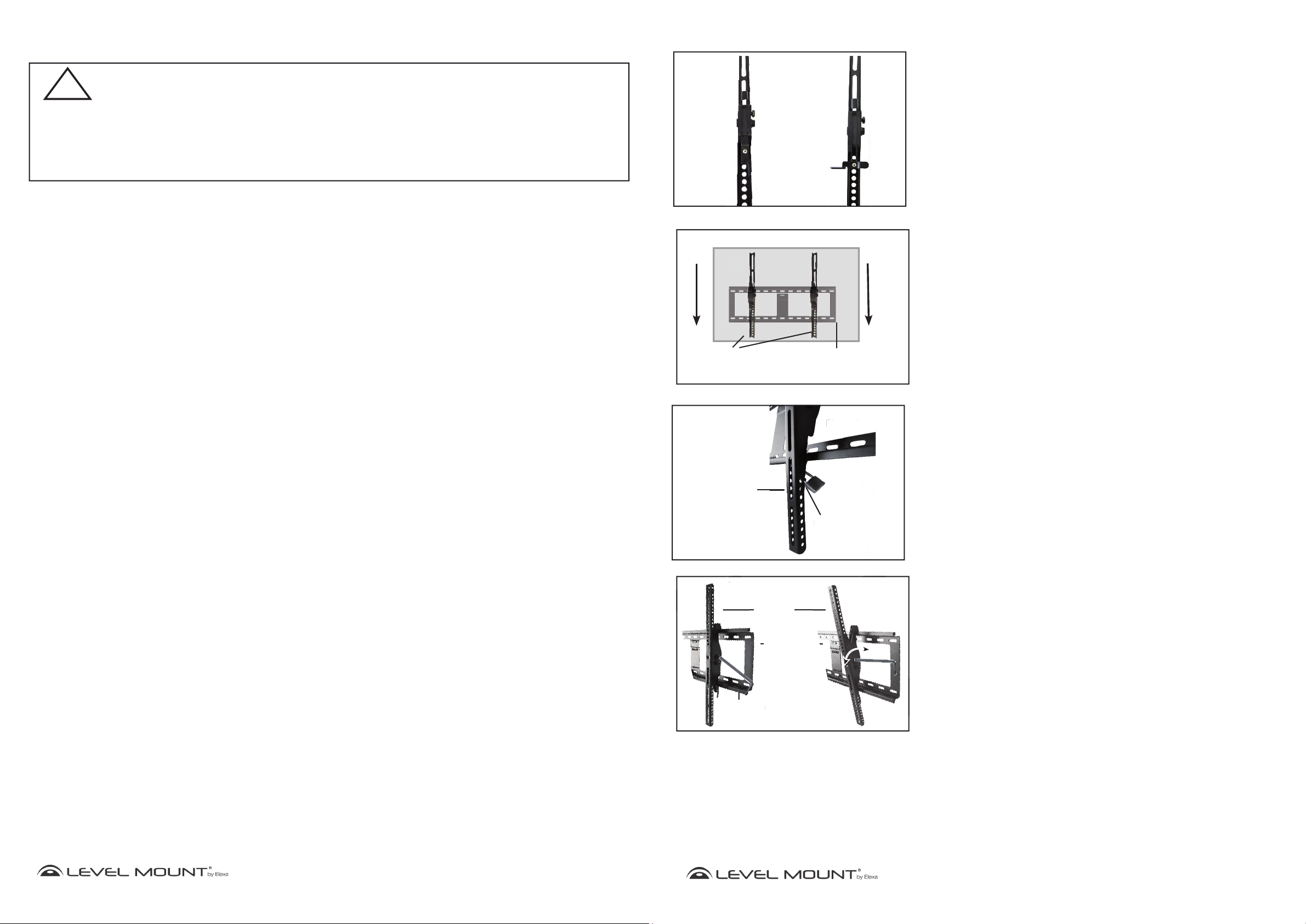
Paso 5 – Montar el televisor de pantalla plana en la placa
de soporte
Antes de montar el televisor de pantalla plana en la Placa de soporte (previamente
fijada a la pared, tal y como se especifica más arriba), primero deberá desbloquear
los brazos fijos o giratorios (que estarán ahora fijos sobre el televisor de pantalla
plana). Para desbloquear los brazos fijos o giratorios, tire de la cuerda hacia arriba,
tal y como muestra la Imagen 17.
Para montar el televisor de pantalla plana en la Placa de soporte, necesitará que 2
personas levanten el televisor de pantalla plana con los brazos fijos o giratorios y los
brazos de extensión, en su caso. Deslice los ganchos de los brazos fijos o giratorios
por encima de la pestaña superior de la Placa de soporte y bájelos hasta que los
brazos fijos o giratorios queden firmemente apoyados a ambos lados de la pestaña
de la Placa de soporte, tal y como muestran las Imágenes 18. Los brazos fijos o
giratorios deben quedar a ras de la Placa de soporte.
Bloquee los Brazos por debajo de la pestaña de la Placa de soporte tirando de
la cuerda, tal y como muestran las Imágenes 17 y 18. Haga lo mismo con el otro
brazo fijo.
5. Make sure all screws and bolts are tightened before allowing the TV Wall Mount to bear the full weight of the TV.
Tighten screws and bolts firmly but do not over-tighten them. Once the screw is flush against the TV and the
screwdriver is more difficult to turn and will not turn further, stop; otherwise there is a risk of over-tightening the
bolt. Over-tightening the screws or bolts could damage the TV Wall Mount, greatly reducing its holding power.
Periodic tightening may be required.
6. Screws should easily and completely thread into the TV mounting holes. If any of the screws provided are not
suitable for the TV Wall Mount system, the installer must not under any circumstances drill holes into the TV or into
the TV Wall Mount components. Using screws of improper size can damage the TV.
7. Do not lift more weight than you can handle. Use at least two people when lifting and positioning the TV on the TV
Wall Mount.
8. Before installing, check to make sure all parts of the TV Wall Mount indicated in these Installation Instructions
are included and undamaged. Never use damaged parts or try to install the TV Wall Mount if you do not have all
needed parts.
9. It is the installer’s responsibility to select the appropriate installation location and the supporting surface on which
to mount this TV Wall Mount and to ensure that the TV Wall Mount is anchored properly to the wall. It is also the
installer’s responsibility to ensure that the TV is properly and securely attached to the TV Wall Mount using only the
enclosed fasteners and components and to verify that the screws and power cords do not touch wires, pipes, or
metal parts within the wall (since this could cause damage to these items or cause electrical shock).
10. Level Mount has made every effort to make these Installation Instructions accurate and complete. However,
Level Mount makes no claim that the information contained herein covers all details, conditions or variations, nor
does it provide for every possible contingency in connection with the installation, assembly or use of this product.
Level Mount makes no representation or warranty, express or implied, regarding the accuracy, completeness or
sufficiency of the information contained in this document. Level Mount is not responsible for any damage or injury
caused by incorrect mounting, assembly, installation or use.
Imagen 19
Brazos
giratorio
Imagen 20
Llave Allen
Brazos
giratorio
Placa de
soporte
Tornillo
Allen
Placa de soporte
Bloqueo
Bl
ue
Paso 6-Bloqueo de la TV en el soporte de pared (opcional)
(Sólo HETWF, HE800T & HE885T)
Opcional: Para bloquear el televisor a la placa de pared, inserte un candado en el
pestillo de bloqueo como se muestra en la Figura 19. Esto evitará que el televisor se
despegó de la placa de pared.
Nota: El bloqueo no está incluido.
Paso 7 – Usar el modo giratorio
(Sólo HETWF, HE800T & HE885T)
Para utilizar la función giratoria o voladiza del brazo, agarre suavemente el televisor
y tire hacia delante de él. El soporte de pared voladizo para televisor se extiende
hasta salir unos 15° de la pared. Después, mueva el televisor hacia arriba o hacia
abajo, tal y como indica la Imagen 20.
www.levelmount.com
4
©2011 Level Mount - Patents Pending
1-888-229-1459
EU: +0044 844 567 2657
UK: 0844 567 2657
25
©2011 Level Mount - Patents Pending
www.levelmount.com
1-888-229-1459
EU: +0044 844 567 2657
UK: 0844 567 2657
Pared de hormigón
Pared de hormigón
rmmi
Placa de soporte
Broca para
madera 12 mm
Tacos para
hormigón
Tornillos
hexagonal
Arandelas
Placa de soporte
Montaje/Instalación
r
tension
Ar
Bo
Nivel de burbuja
incorporado/
Nivel
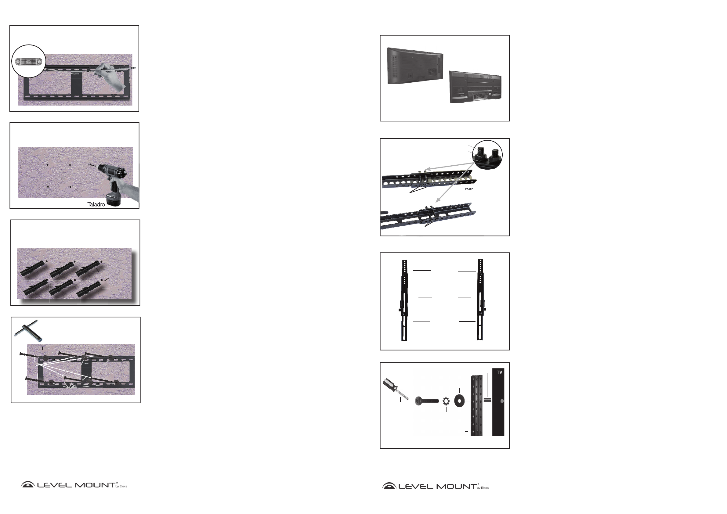
Imagen 13
Pared de hormigón
Opción B – Si las paredes son de hormigón
Para fijar la Placa de soporte al hormigón, colóquela a la altura deseada. Marque
los 6 agujeros con un lápiz cuando haya nivelado la Placa de Soporte usando el
Nivel de burbuja que viene incorporado o el nivel, tal y como muestra la Imagen
13.
Deje la Placa de soporte a un lado. Taladre 6 agujeros en el hormigón, en el lugar
marcado, tal y como muestran las Imágenes 14. Para taladrar los agujeros de los
tacos para hormigón (Bolsa 6) en el hormigón, utilice un taladro eléctrico con una
broca de 12 mm para madera.
Cuidado:
hormigón.
No utilice un martillo neumático, pues rompería y debilitaría el
Assembly/Installation
Figure 1
Flat Back
Step 1 – Selecting the Correct Hardware Based on TV
Back
Before beginning the installation, determine if the TV has a flat back or a
recessed back as shown in Figure 1. If you have a recessed back TV you may
need to use the spacers (Bag 5) as shown in Figures 4 and 6. The spacer
is used to fill the recessed area of the TV so that the TV Bracket is fully
supported and flush with the back of the TV.
Placa de soporte
Imagen 14
Pared de hormigón
Broca para
madera 12 mm
Imagen 15
Pared de hormigón
Tacos para
hormigón
Inserte los tacos para hormigón (Bolsa 6) en los agujeros, tal y como muestra la
Imagen 15, e introdúzcalos con un martillo hasta que queden a ras de la pared de
hormigón, como muestra la Imagen 15.
Para fijar la Placa de soporte a la pared de hormigón, utilice la llave hexagonal
para atornillar los 6 tornillos hexagonales con arandelas (Bolsa 6) en cada uno de
los tacos de hormigón, tal y como muestra la Imagen 16. Atornille bien, hasta que
quede fijo, pero con cuidado de no pasarse de rosca, pues de lo contrario podría
dañar el soporte o los tornillos.
Cuidado:
Debido al peso del televisor de pantalla plana, es fundamental
que utilice los 6 tornillos para fijar la Placa a la pared.
M5 Bolt
Figure 2
M5Bolt
Recessed Back
Bolt
Nut
Lock Washer
Upper
Extension Arm
Extension Arm
Figure 3
Upper
Extension
Arms
Step 2 - Extension Arm Installation (if needed)
If the holes on the Fixed Arms do not line up with the holes in back of the
TV, do not drill. Instead, follow these instructions for the Extension Arm
Installation. Otherwise, skip to Step 3.
Step 2a - Attaching Extension Arms to Fixed or Tilt Arms
Attach the Extension Arms to the Fixed or Tilt Arms using the following hardware
as shown in Figure 2:
• Bolts M5 (Bag 7)
• Lock Washer M5 (Bag 7)
• Extension Arm
• Fixed or Tilt Arm
• Hex Nut M5 (Bag 7)
Adjust the bolt in Figure 2 to move the extension arms to align with the holes on
the back of the Flat Panel TV.
Lower
Step 2b - Completed Extension Arm Attachment
All 4 Extension Arms should be attached in the same manner. When completed,
your Fixed or Tilt Arms with the Extension Arms attached, should appear as
shown in Figure 3.
Tornillos
hexagonal
Imagen 16
Llave hexagonal
Arandelas
Pared de hormigón
Placa de soporte
24
www.levelmount.com
1-888-229-1459
EU: +0044 844 567 2657
©2011 Level Mount - Patents Pending
UK: 0844 567 2657
Fixed or
TIlt Arms
Lower
Extension
Arms
(NTPFW Arms shown)
Figure 4
M4, M5 , M6
or M8 Bolt
Phillips
Screwdriver
M4, M5, M6 or M8
Extension Arm
Only use Spacer if Flat Panel TV
has a recessed back
Washer
Lock Washer
Spacer
Step 2c - Attaching Extension Arms to the Back of the
TV
There are bolts of varying lengths included in this package, located in (Bags
1 through 5). Please use the bolt with the appropriate length for your TV.
Small TVs need the following hardware: (For most TVs under 50’’ or 127cm)
• Bolt M4 (Bag 1) or Bolt M5 (Bag 2)
• Lock Washer M4 (Bag 1) or Lock Washer M5 (Bag 2)
• Washer 20mm x 5.5mm x 1.0mm (Bag 5)
• An additional Washer may be needed to prevent the bolt head from
recessing into the back of the TV
• Extension Arm
• Spacer (Bag 5) Only needed if TV has a recessed back.
www.levelmount.com
5
©2011 Level Mount - Patents Pending
1-888-229-1459
EU: +0044 844 567 2657
UK: 0844 567 2657
 Loading...