

UK
Installation instructions
DELUXE 10’ CORD MANAGEMENT
SYSTEM (EZEW7-01)
The EasyMount Cord Management System
is the simple solution for concealing and
grouping the variety of cords attached to your
television monitor.
BEFORE YOU BEGIN
Caution: To prevent damage to the Cord
Management System or to the equipment
that is attached to it, please follow the instructions carefully.
When painting the Cord Management System,
please paint and allow to completely dry
BEFORE installation on a wall. This will allow
for the most professional result without drips
and runs.
** It is recommended to get a person to
dismount and hold the television while
fastening the pan screws into the wall
TOOLS REQUIRED FOR INSTALLATION
Phillips screwdriver
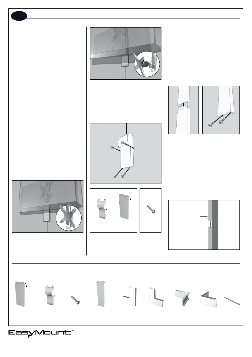
STEP 1:
Before you begin installing the Cord
Management System, you must determine
which piece is best to attach.
cord cover is in a perfectly vertical position
prior to attaching the pan screws. We recommend using a level, or measuring 2 points
equal distance from the corner of the room.
This will allow the cord cover to be straight
when all segments are attached. You may want
to use the nail included in the kit to begin a
basic hole before fastening the Pan Screws. Do
not over tighten the screws.
STEP 3:
If you have an EasyMount Swivel/Tilt (EZSJ),
Swivel/Tilt/Extended Mount (EZDJ) or any
other similar mount then use the 4” Rounded
Cover to begin installation.
STEP 2:
Diagram 1 Diagram 2
Next, determine which piece will best fit your
needs. To attach a Cord Management section,
slide the lip of a Cord Management piece
inside of the initial 4” Flat or 4” Rounded
section (Diagram 1). Utilize a nail to start the
hole allowing you to more easily fasten the
2 pan screws into the bottom of the Cord
Management section (Diagram 2). After the
screws are fastened, attach another Cord
Management section and repeat until cords
are covered. Do not over tighten screws.
4” Round
If you have an EasyMount Fixed Wall Mount
(EZFW) or any other similar mount then use the
4” Flat Cord Cover to begin installation.
(1x) 4’’ Flat
Section
2005 Market Link USA, Inc., All rights reserved. EasyMount, the EasyMount design,
and other related logos are trademarks of Market Link USA, Inc.
(1x) 4’’ Rounded
Section
(44x) 3⁄4’’ Pan
Screws
After determining which section fits your needs,
place the cord cover over your cord(s) and use
a Phillips screwdriver to fasten the 4 pan screws
into the initial first section. Make sure that the
(12) 8’’ Straight
Section
Section
OR
4” Flat
Section
KIT INCLUDES
(1x) 6’’ Left
Corner
3⁄4’’ Pan
Screws
(1x) 6’’ Right
Corner
4” Cord Cover
Lip
Additional Section
(1x) 6’’ Inside
Corner
Side View
Corner
www.EasyMount.net
1-888-229-1459
©2005 EasyMount
Patents Pending
Wall
(1x) Nail(1x) 6’’ Outside
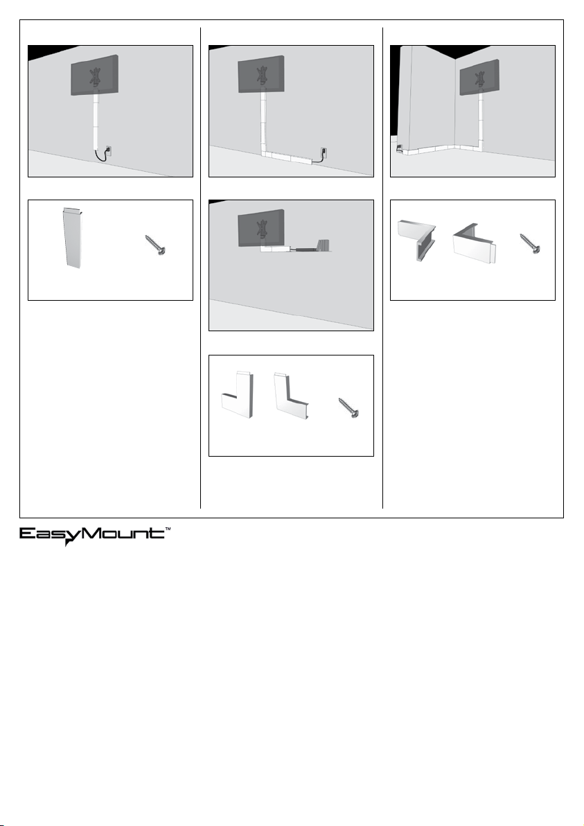
Straight Section:
Left & Right Corner Section:
Inside and Outside Corner Section:
Diagram 3
8” Straight Section 3⁄4” Pan
Screws
Utilize the 8” straight section if you would like
to guide your cords directly down the wall
to an outlet. Repeat until cords are covered.
(Diagram 3).
Utilize the left and right corner sections for
guiding the cords along a walls edge or television to an outlet or electrical component
(Diagram 4 & 5).
2005 Market Link USA, Inc., All rights reserved. EasyMount, the EasyMount design,
and other related logos are trademarks of Market Link USA, Inc.
6” Left
Corner
Diagram 4
Diagram 5
6” Right
Corner
3⁄4” Pan
Screws
Diagram 6
6” Inside
Corner
6” Outside
Corner
3⁄4” Pan
Screws
Utilize the inside and outside corner sections
to go around corners (Diagram 6).
www.EasyMount.net
1-888-229-1459
©2005 EasyMount
Patents Pending

Instrucciones de instalación
E
SISTEMA DE CORDÓN DE ENRUTAMIENTO
DELUXE 10’ (EZEW7-01)
El sistema de cordón de enrutamiento
EasyMount es una solución sencilla para
ocultar y agrupar la diversidad de cables del
monitor de su televisor.
ANTES DE EMPEZAR
Precaución: Para evitar daños al sistema
de cordón de enrutamiento o al equipo al
que va acoplado, siga cuidadosamente las
instrucciones.
Cuando pinte el sistema de cordón de
enrutamiento, permita que la pintura se
seque completamente ANTES de efectuar
la instalación en la pared. Obtendrá los
mejores resultados profesionales sin gotas
ni rebabas.
** Le recomendamos que pida a otra persona que le ayuda a desmontar el televisor
y sujetarlo mientras fija los tornillos de
cabeza plana a la pared.
HERRAMIENTAS NECESARIAS PARA LA
INSTALACIÓN
Destornillador de estrella.
PASO 1:
Antes de iniciar la instalación del sistema de
cordón de enrutamiento, tiene que determinar qué pieza le conviene utilizar.
Si tiene una fijación de pared estática
EasyMount™ (EZFW) o alguna otra fijación
similar, para iniciar la instalación utilice la
tapa de cordón plana de 4”.
Si tiene una fijación EasyMount™ giratoria/
de inclinación (EZSJ), o giratoria/de inclinación/extensión (EZDJ) o alguna otra fijación
similar, para iniciar la instalación utilice la tapa
de cordón redonda de 4”.
PASO 2:
O
Sección
redonda
sección plana
Tornillos de
cabeza plana
de 3⁄4”
Después de determinar qué sección responde
a sus necesidades, coloque la tapa del cordón
sobre el/los cable(s) y con un destornillador
de estrella fije los 4 tornillos de cabeza plana
en la primera sección inicial. Antes de fijar
los tornillos de cabeza plana, asegúrese de
que la tapa del cordón esté perfectamente
vertical. Le recomendamos utilizar un nivel, o
que marque 2 puntos a igual distancia de las
esquinas de la habitación. Esto permitirá que
la tapa del cordón quede totalmente recta
cuando se le incorporen todos los segmentos. Para marcar un agujero de referencia
antes de fijar los tornillos de cabeza plana,
puede serle útil el clavo incluido en el kit. No
apriete demasiado los tornillos.
PASO 3:
Diagrama 1 Diagrama 2
A continuación, determine qué pieza responde
mejor a sus necesidades. Para fijar una sección
del cordón de enrutamiento, deslice el saliente
de la pieza del cordón de enrutamiento por
dentro de la sección inicial plana de 4” o
redonda de 4” (Diagrama 1). Utilice un clavo
para marcar el agujero, pues le permitirán fijar
con mayor facilidad los 2 tornillos de cabeza
plana en el extremo inferior de la sección del
cordón de enrutamiento (Diagrama 2). Una
vez fijados los tornillos, acople otra sección del
cordón de enrutamiento y repita la operación
hasta que todos los cables queden cubiertos.
No apriete demasiado los tornillos.
Tapa de cordón
de 4”
Saliente
Sección adicional
Vista lateral
Pared
(1x) sección
plana de 4”
2005 Market Link USA, Inc., todos los derechos reservados. Easymount, el diseño EasyMount
y otros logos relacionados son marcas registradas de Market Link USA, Inc.
(1x) sección
redonda
de 4”
(44x) tornillos
de cabeza
plana de 3⁄4”
(12x) sección
recta de 8”
EL KIT INCLUYE
(1x) borde
izquierdo de 6”
(1x) borde
derecho de 6”
(1x) borde
interior de 6”
exterior de 6”
www.EasyMount.net
1-888-229-1459
©2005 EasyMount
Patentes pendientes
(1x) clavo(1x) borde

Sección recta:
Secciones para las esquinas izquierda y
derecha:
Sección de las esquinas interior y exterior:
Diagrama 3
Sección recta de 8”
Tornillos de
cabeza plana
de 3⁄4”
Si quiere enrutar los cables directamente hacia
el suelo hasta una toma de corriente, utilice
la sección recta de 8”. Repita la operación
hasta que todos los cables estén cubiertos.
(Diagrama 3).
Esquina
izquierda 6”
Para guiar los cables a lo largo de una esquina
o alrededor del televisor hasta una toma de
corriente o componente eléctrico, utilice las
secciones para las esquinas derecha e izquierda. (Diagramas 4 y 5).
2005 Market Link USA, Inc., todos los derechos reservados. Easymount, el diseño EasyMount
y otros logos relacionados son marcas registradas de Market Link USA, Inc.
Diagrama 4
Diagrama 5
Esquina
derecha 6”
Tornillos de
cabeza plana
de 3⁄4”
Diagrama 6
Esquina
interior 6”
Esquina
exterior 6”
Tornillos de
cabeza plana
de 3⁄4”
Para bordear las esquinas, utilice las secciones
de esquina interior y exterior (Diagrama 6).
www.EasyMount.net
1-888-229-1459
©2005 EasyMount
Patentes pendientes

FR
Instructions d’installation
SYSTÈME DE GESTION DE CÂBLES EXTERNE
DELUX 10’ (EZEW7-01)
Le système de gestion de câbles EasyMount
est la solution simple pour dissimuler et grouper les différents câbles reliés à votre moniteur
de télévision.
AVANT DE COMMENCER
Attention : Pour éviter d’endommager le kit
de gestion de câbles ou l’appareil auquel il est
raccordé, veuillez vous conformer scrupuleusement aux instructions suivantes.
Si vous peignez le kit de gestion de câbles,
peignez-le et laissez-le sécher complètement
AVANT son installation au mur. Cela vous assurera des résultats professionnels sans gouttes ni
coulures de peinture.
** Il est conseillé de vous faire aider par
une personne pour démonter et soutenir le
téléviseur lorsque vous fixez les vis à tête
cylindrique dans le mur.
OUTILLAGE REQUIS POUR L’INSTALLATION
Tournevis cruciforme
ETAPE 1:
Avant de commencer l’installation du système
de gestion de câbles, vous devez déterminer la
pièce adéquate à fixer.
Si vous disposez d’un support mural fixe
EasyMount™ (EZFW) ou de tout autre type
de support similaire, utilisez le cache-câbles
plat 4’’ pour commencer l’installation.
Si vous disposez d’un support mural pivotant/
inclinable EasyMount™ (EZSJ), pivotant/inclinable/extensible (EZDJ) ou encore de tout
autre type de support similaire, utilisez le
cache-câbles rond 4’’ pour commencer l’installation.
ETAPE 2:
OU
Vis à tête
Cache-câbles
rond 4’’
Cache-câbles
plat 4’’
cylindrique
3/4’’
Après avoir déterminé la pièce correspondant
à vos besoins, placez le cache-câbles sur vos
câbles et utilisez un tournevis cruciforme pour
fixer les quatre vis à tête cylindrique dans la
première pièce initiale. Assurez-vous que le
cache-câbles se trouve en position parfaitement
verticale avant de fixer les vis à tête cylindrique. Nous vous conseillons d’employer un
niveau ou de mesurer deux points à égale
distance de l’angle de la pièce. Cela permettra au cache-câbles d’être d’aplomb lorsque
tous les segments seront fixés. Vous pouvez
également utiliser le clou fourni avec le kit
pour réaliser un simple orifice avant de fixer
les vis à tête cylindrique. Ne serrez pas les vis
de manière excessive.
ETAPE 3:
Diagramme 1 Diagramme 2
Déterminez à présent la pièce qui répond le
mieux à vos besoins. Pour fixer une section
de cache-câbles, faites glisser la lèvre d’un
cache-câbles à l’intérieur du cache-câbles plat
4’’ ou rond 4’’ initial (Diagramme 1). Utilisez
un clou pour commencer le trou de manière
à pouvoir visser plus facilement les deux vis à
tête cylindrique dans la base du cache-câbles
(Diagramme 2). Après avoir fixé les vis, fixez
une autre section de cache-câbles et répétez
l’opération jusqu’à ce que les câbles soient
entièrement dissimulés. Ne serrez pas les vis
de manière excessive.
Cache-câbles 4’’
Lèvre
Section additionnelle
Vue latérale
Mur
Cache-câbles
plat 4’’ (1x)
2005 Market Link USA, Inc. Tous droits réservés. Easymount, le design EasyMount
et les autres logos liés sont des marques commerciales de Market Link USA, Inc.
Cache-câbles
rond 4’’ (1x)
Vis à tête
cylindrique
3/4’’ (44x)
Cache-câbles
droit 8’’ (12x)
LE KIT COMPREND
Angle gauche
6’’ (1x)
Angle droit
6’’ (1x)
Angle intérieur
6’’ (1x)
6’’ (1x)
Clou (1x)Angle extérieur
www.EasyMount.net
1-888-229-1459
©2005 EasyMount
Brevets en instance

Section droite :
Cache-câbles d’angle gauche et droit :
Cache-câbles intérieurs et extérieurs :
Diagramme 3
Cache-câbles plat 8’’ Vis à tête
cylindrique 3/4’’
Utilisez des sections de cache-câbles droite 8’’
si vous préférez guider vos câbles directement
vers une prise de courant située le bas du mur.
Répétez l’opération jusqu’à ce que les câbles
soient entièrement dissimulés (Diagramme 3).
Cache-câbles
gauche 6’’
Utilisez des sections de cache-câbles gauches
ou droites pour guider vos câbles le long du mur
ou du téléviseur vers une prise de courant ou un
composant électrique (Diagrammes 4 et 5).
2005 Market Link USA, Inc. Tous droits réservés. Easymount, le design EasyMount
et les autres logos liés sont des marques commerciales de Market Link USA, Inc.
Diagramme 4
Diagramme 5
Cache-câbles
droit 6’’
Vis à tête
cylindrique
3/4’’
Diagramme 6
Cache-câbles
intérieur 6’’
Cache-câbles
extérieur 6’’
Vis à tête
cylindrique
3/4’’
Utilisez des sections de cache-câbles intérieures et extérieures pour guider vos câbles
autour des arêtes des murs (Diagramme 6).
www.EasyMount.net
1-888-229-1459
©2005 EasyMount
Brevets en instance
 Loading...