

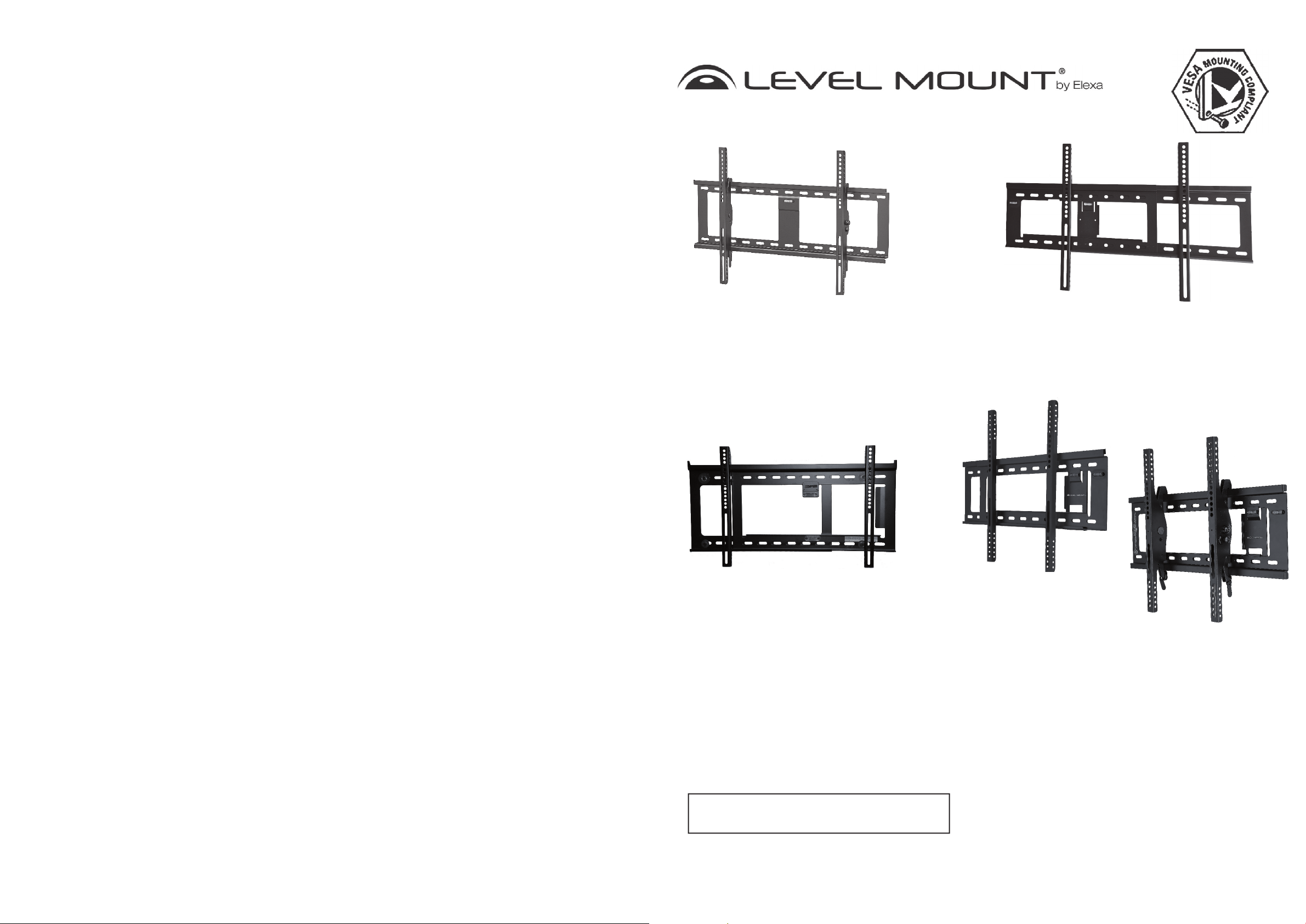
Installation Instructions
Extra Large Tilt TV Wall Mount fi ts
37”- 85” (939,8 mm - 2159 mm)
Flat Panel Displays - up to 200 lb
(90kg) capacity - Black (HE800T.
HE885T)
Adjustable Fixed TV Wall Mount fi ts
26”-85” (660,4 mm - 2159 mm)
Flat Panel Displays - up to 200 lb
(90kg) capacity - Black (DC65ADLP,
LM65ADLP & ELPFW-07)
Adjustable Fixed TV Wall Mount
fi ts 26”- 85” (660,4 mm - 2159 mm)
Flat Panel Displays - up to 200 lb
(90kg) capacity - Black (NTPFW,
LMPFW85)
Adjustable Fixed or Tilt TV Wall
Mount fi ts 26”-85” (660,4 mm -
2159 mm) Flat Panel Displays
- up to 200 lb (90kg) capacity Black (HETWF)
Please read these Installation Instructions entirely, including the Warnings, before you start
the installation and assembly of the TV Wall Mount.
Instructions en Francais, Page 10
Instrucciones en Español, Página 18
Need Help?
Helpful Hints
If you have installation questions about your TV Wall Mount, please go to www.levelmount.com to view
product tutorials.
Contacting Level Mount Customer Service
If you have questions, our trained Customer Service Department is happy to assist you 24 hours a day,
7 days a week, every day of the year. Contact Level Mount Customer Service as follows:
• In the United States dial: 1-888-229-1459
• In Europe dial: +0044 844 567 2657
• In the United Kingdom dial: 0844 567 2657
• E-mail Level Mount at www.customersupport@elexausa.com
DO NOT RETURN THIS PRODUCT TO THE STORE OR WEB SITE FROM WHICH IT WAS
PURCHASED
If you believe the product is defective, has a missing or broken part or are having diffi culty with
assembly, please contact Level Mount directly 24 hours a day, 7 days a week, 365 days a year as listed
above, for a quick and effi cient solution to your problem.
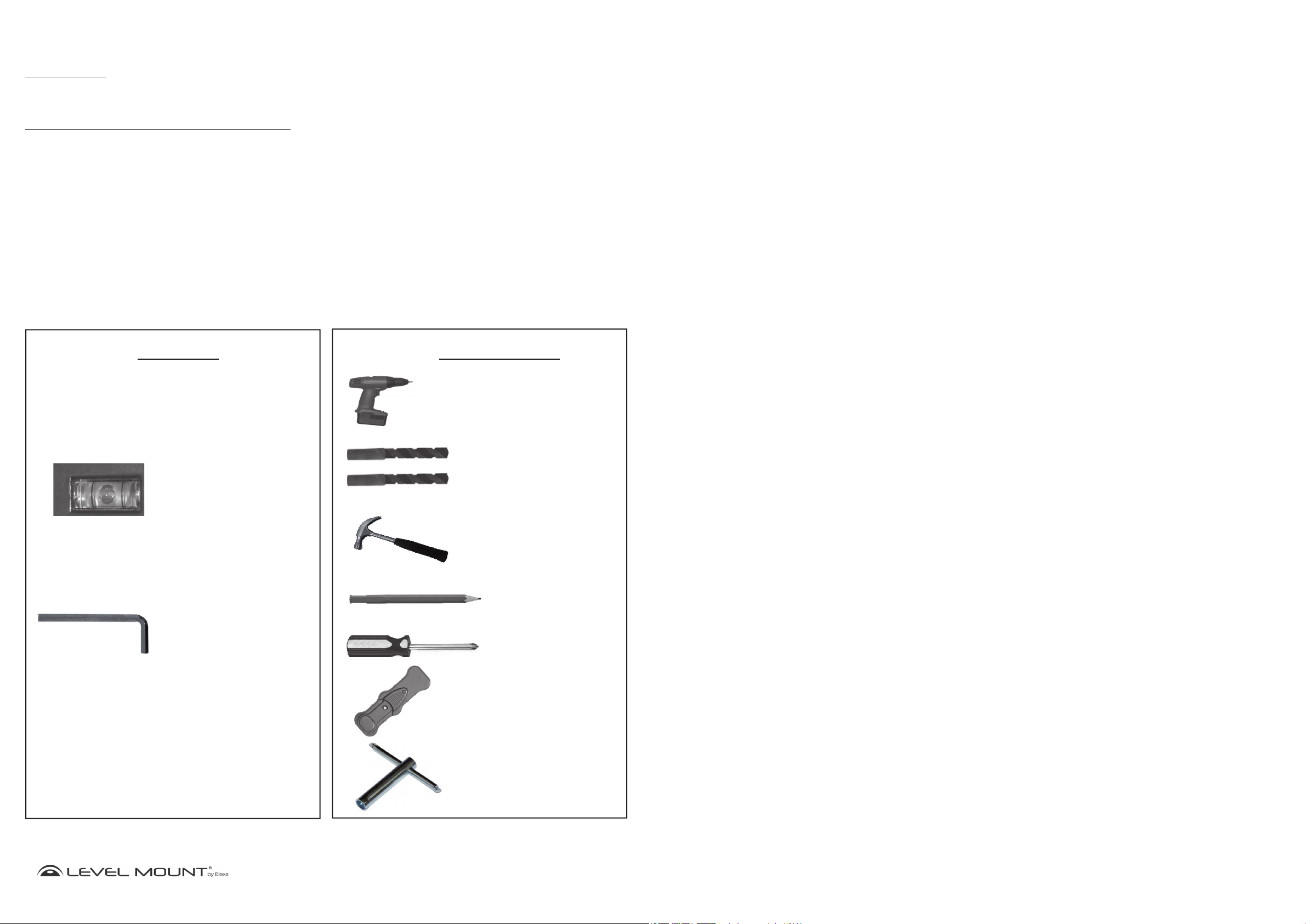
Tools Required
Included
Built-in Bubble Level
Spirit Level
Allen Wrench
(HETWF, HE800T,
HE885T)
Not Included
Drill Bit 4mm
Drill Bit Masonry 12mm
Hammer
Pencil
Phillips
Screwdriver
Stud Finder
Hex Wrench
www.levelmount.com
2
©2011 Level Mount - Patents Pending
1-888-229-1459
EU: +0044 844 567 2657
UK: 0844 567 2657
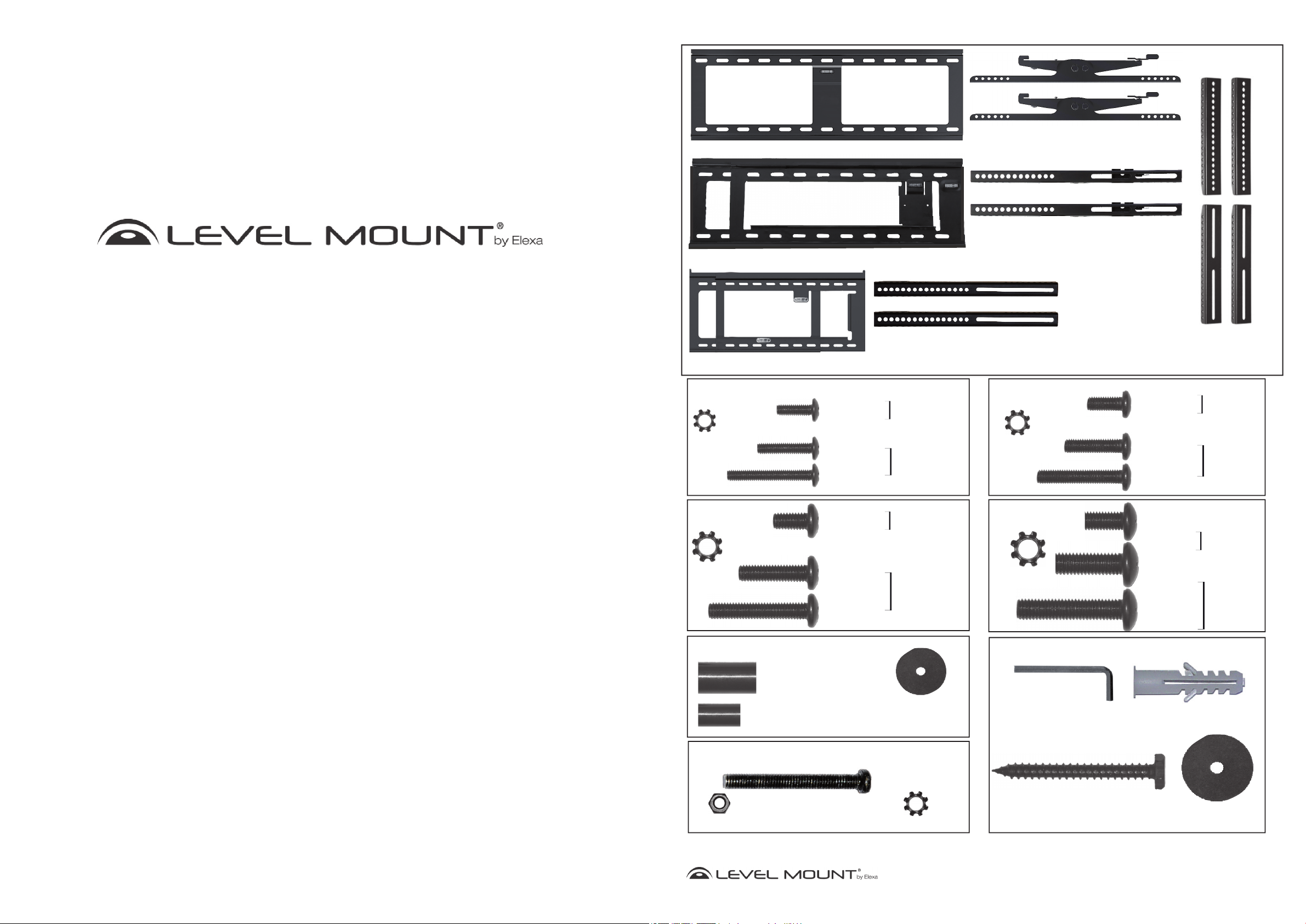
What’s in the box?
Wall Plate - HE800T, HE885T
Wall Plate - HETWF, NTPFW, LMPFW85
Tilt Arms - HETWF, HE800T, HE885T
Fixed Arms - HETWF, NTPFW, LMPFW85
© 2012. All rights reserved. Patents Pending. Level Mount is a trademark of Elexa Consumer
Products, Inc. All other trademarks are the property of their respective owners.
© 2012. Tous droits réservés. Brevets en instance Level Mount est une marque déposée de
Elexa Consumer Products, Inc. Toutes les autres marques de commerce appartiennent à leurs proprié-
taires ou détenteurs respectifs.
© 2012. Todos los derechos reservados. Pendiente de patente. Level Mount es una marca registrada
de Elexa Consumer Products, Inc. El resto de marcas registradas pertenecen a sus correspondi-
entes dueños.
Wall Plate - 65ADLP, ELPFW-07
Bag 1
(4) M4 Lock Washer
Bag 3
(4) M6 Lock Washer
(4) M4 x 12mm
Phillips Bolt
(4) M4 x 20mm
Phillips Bolt
(4) M4 x 30mm
Phillips Bolt
(4) M6 x 12mm
Phillips Bolt
(4) M6 x 24mm
Phillips Bolt
(4) M6 x 35mm
Phillips Bolt
Bag 5
Fixed Arms - 65ADLP, ELPFW-07
Bag 2
Flat Back
TV Hardware
Recessed
Back
TV Hardware
Flat Back
TV Hardware
Recessed
Back
TV Hardware
(4)M5 Lock Washer
Bag 4
(4) M8 Lock Washer
Bag 6
(4) M5 x 12mm
Phillips Bolt
(4) M5 x 20mm
Phillips bolt
(4) M5 x 30mm
Phillips Bolt
(4) M8 x 16mm
Phillips Bolt
(4) M8 x 25mm
Phillips Bolt
(4) M8 x 40mm
Phillips Bolt
Extension Arms
Flat Back
TV Hardware
Recessed
Back
TV Hardware
Flat Back
TV Hardware
Recessed
Back
TV Hardware
Bag 7
(8) M5 Nut
(4) Spacer
Ø17.5 x Ø8.3 x 22.5 mm
(4) Spacer
Ø12.5 x Ø5.5 x 16.5 mm
Phillips Bolt
(4) Washer
Ø20 x Ø5.5 x 1.0 mm
(8) M5 x 40mm
(8) M5 Lock Washer
(1) Allen Wrench Key
(HETWF, HE800T,
HE885T)
(6) Hex Wood Screw
Ø6.3 x 75mm
3
(6) Concrete Anchors
Ø12 x 60 mm
28mm x Ø8mm x 1.5mm
©2011 Level Mount - Patents Pending
(6) Washer
www.levelmount.com
EU: +0044 844 567 2657
UK: 0844 567 2657
1-888-229-1459
Getting Started
Placa de soporte
Pegado a la
Pared
Brazos fijos o
en la pared
posterior de la televisión
Brazos
Brazos
Placa de
soporte
TVTV
a
ave Alle
n
Allen
o
o
o
!
These TV Wall Mounts were designed specifically to hold TVs with a maximum weight of up to 200
lbs (90kg) and with the following dimensions: 37” - 85” (939,8 mm - 2159 mm) HE800T, HE885T
and 26” - 85” (660,4 mm - 2159 mm) NTPFW, LMPFW85, DC65ADLP, LM65ADLP, ELPFW-07,
HETWF. Using this product with a TV heavier than the maximum weight, or that exceeds these
dimensions, may result in serious personal injury and damage to equipment and property.
1. Do not begin the installation of the TV Wall Mount until you have read and understood the instructions and warnings
contained in these Installation Instructions. Failure to read, thoroughly understand and follow the instructions can
result in serious personal injury and damage to equipment and property. It is the installer’s responsibility to make
sure all components are properly assembled and installed using the instructions provided.
2. If you have questions that do not appear to be covered in these Installation Instructions, please refer to the “Helpful
Hints” section of the detail page for the TV Wall Mount or contact us as described under the “Need Help” section.
If you are at all unsure about any step in these instructions or your ability to install the TV Wall Mount safely and
securely, you should seek professional help from a qualified contractor.
3. This TV Wall Mount contains small items that could be a hazard if swallowed. Keep these items away from
children.
4. The TV Wall Mount must be attached to wood studs or to properly installed anchors in concrete. Do not install the
TV Wall Mount only to drywall or plasterboard. If mounting to wood studs, make sure that mounting screws are
anchored into the center of the studs. See Stud Finder Instructions, included below. Do not use the TV Wall Mount
for devices other than as specified in these instructions.
CAUTION!
Montaje/Instalación
Imagen 17
Brazo fijo o
giratorio
bloqueado
Brazo fijo o
giratorio
desbloqueado
Imagen 18
TV
Brazos fijos o
posterior de la televisión
giratorio
en la pared
Placa de soporte
Pegado a la
Pared
Paso 5 – Montar el televisor de pantalla plana en la placa
de soporte
Antes de montar el televisor de pantalla plana en la Placa de soporte (previamente
fijada a la pared, tal y como se especifica más arriba), primero deberá desbloquear
los brazos fijos o giratorios (que estarán ahora fijos sobre el televisor de pantalla
plana). Para desbloquear los brazos fijos o giratorios, tire de la cuerda hacia arriba,
tal y como muestra la Imagen 17.
Para montar el televisor de pantalla plana en la Placa de soporte, necesitará que 2
personas levanten el televisor de pantalla plana con los brazos fijos o giratorios y los
brazos de extensión, en su caso. Deslice los ganchos de los brazos fijos o giratorios
por encima de la pestaña superior de la Placa de soporte y bájelos hasta que los
brazos fijos o giratorios queden firmemente apoyados a ambos lados de la pestaña
de la Placa de soporte, tal y como muestran las Imágenes 18. Los brazos fijos o
giratorios deben quedar a ras de la Placa de soporte.
Bloquee los Brazos por debajo de la pestaña de la Placa de soporte tirando de
la cuerda, tal y como muestran las Imágenes 17 y 18. Haga lo mismo con el otro
brazo fijo.
5. Make sure all screws and bolts are tightened before allowing the TV Wall Mount to bear the full weight of the TV.
Tighten screws and bolts firmly but do not over-tighten them. Once the screw is flush against the TV and the
screwdriver is more difficult to turn and will not turn further, stop; otherwise there is a risk of over-tightening the
bolt. Over-tightening the screws or bolts could damage the TV Wall Mount, greatly reducing its holding power.
Periodic tightening may be required.
6. Screws should easily and completely thread into the TV mounting holes. If any of the screws provided are not
suitable for the TV Wall Mount system, the installer must not under any circumstances drill holes into the TV or into
the TV Wall Mount components. Using screws of improper size can damage the TV.
7. Do not lift more weight than you can handle. Use at least two people when lifting and positioning the TV on the TV
Wall Mount.
8. Before installing, check to make sure all parts of the TV Wall Mount indicated in these Installation Instructions
are included and undamaged. Never use damaged parts or try to install the TV Wall Mount if you do not have all
needed parts.
9. It is the installer’s responsibility to select the appropriate installation location and the supporting surface on which
to mount this TV Wall Mount and to ensure that the TV Wall Mount is anchored properly to the wall. It is also the
installer’s responsibility to ensure that the TV is properly and securely attached to the TV Wall Mount using only the
enclosed fasteners and components and to verify that the screws and power cords do not touch wires, pipes, or
metal parts within the wall (since this could cause damage to these items or cause electrical shock).
10. Level Mount has made every effort to make these Installation Instructions accurate and complete. However,
Level Mount makes no claim that the information contained herein covers all details, conditions or variations, nor
does it provide for every possible contingency in connection with the installation, assembly or use of this product.
Level Mount makes no representation or warranty, express or implied, regarding the accuracy, completeness or
sufficiency of the information contained in this document. Level Mount is not responsible for any damage or injury
caused by incorrect mounting, assembly, installation or use.
Imagen 19
Brazos
giratorio
Imagen 20
Llave Allen
Brazos
giratorio
Placa de
soporte
Tornillo
Allen
Placa de soporte
Bloqueo
Bl
ue
Paso 6-Bloqueo de la TV en el soporte de pared (opcional)
(Sólo HETWF, HE800T & HE885T)
Opcional: Para bloquear el televisor a la placa de pared, inserte un candado en el
pestillo de bloqueo como se muestra en la Figura 19. Esto evitará que el televisor se
despegó de la placa de pared.
Nota: El bloqueo no está incluido.
Paso 7 – Usar el modo giratorio
(Sólo HETWF, HE800T & HE885T)
Para utilizar la función giratoria o voladiza del brazo, agarre suavemente el televisor
y tire hacia delante de él. El soporte de pared voladizo para televisor se extiende
hasta salir unos 15° de la pared. Después, mueva el televisor hacia arriba o hacia
abajo, tal y como indica la Imagen 20.
www.levelmount.com
4
©2011 Level Mount - Patents Pending
1-888-229-1459
EU: +0044 844 567 2657
UK: 0844 567 2657
25
©2011 Level Mount - Patents Pending
www.levelmount.com
1-888-229-1459
EU: +0044 844 567 2657
UK: 0844 567 2657
Pared de hormigón
Pared de hormigón
rmmi
Placa de soporte
Broca para
madera 12 mm
Tacos para
hormigón
Tornillos
hexagonal
Arandelas
Placa de soporte
Montaje/Instalación
r
tension
Ar
Bo
Nivel de burbuja
incorporado/
Nivel
Imagen 13
Pared de hormigón
Opción B – Si las paredes son de hormigón
Para fijar la Placa de soporte al hormigón, colóquela a la altura deseada. Marque
los 6 agujeros con un lápiz cuando haya nivelado la Placa de Soporte usando el
Nivel de burbuja que viene incorporado o el nivel, tal y como muestra la Imagen
13.
Deje la Placa de soporte a un lado. Taladre 6 agujeros en el hormigón, en el lugar
marcado, tal y como muestran las Imágenes 14. Para taladrar los agujeros de los
tacos para hormigón (Bolsa 6) en el hormigón, utilice un taladro eléctrico con una
broca de 12 mm para madera.
Cuidado:
hormigón.
No utilice un martillo neumático, pues rompería y debilitaría el
Assembly/Installation
Figure 1
Flat Back
Step 1 – Selecting the Correct Hardware Based on TV
Back
Before beginning the installation, determine if the TV has a flat back or a
recessed back as shown in Figure 1. If you have a recessed back TV you may
need to use the spacers (Bag 5) as shown in Figures 4 and 6. The spacer
is used to fill the recessed area of the TV so that the TV Bracket is fully
supported and flush with the back of the TV.
Placa de soporte
Imagen 14
Pared de hormigón
Broca para
madera 12 mm
Imagen 15
Pared de hormigón
Tacos para
hormigón
Inserte los tacos para hormigón (Bolsa 6) en los agujeros, tal y como muestra la
Imagen 15, e introdúzcalos con un martillo hasta que queden a ras de la pared de
hormigón, como muestra la Imagen 15.
Para fijar la Placa de soporte a la pared de hormigón, utilice la llave hexagonal
para atornillar los 6 tornillos hexagonales con arandelas (Bolsa 6) en cada uno de
los tacos de hormigón, tal y como muestra la Imagen 16. Atornille bien, hasta que
quede fijo, pero con cuidado de no pasarse de rosca, pues de lo contrario podría
dañar el soporte o los tornillos.
Cuidado:
Debido al peso del televisor de pantalla plana, es fundamental
que utilice los 6 tornillos para fijar la Placa a la pared.
M5 Bolt
Figure 2
M5Bolt
Recessed Back
Bolt
Nut
Lock Washer
Upper
Extension Arm
Extension Arm
Figure 3
Upper
Extension
Arms
Step 2 - Extension Arm Installation (if needed)
If the holes on the Fixed Arms do not line up with the holes in back of the
TV, do not drill. Instead, follow these instructions for the Extension Arm
Installation. Otherwise, skip to Step 3.
Step 2a - Attaching Extension Arms to Fixed or Tilt Arms
Attach the Extension Arms to the Fixed or Tilt Arms using the following hardware
as shown in Figure 2:
• Bolts M5 (Bag 7)
• Lock Washer M5 (Bag 7)
• Extension Arm
• Fixed or Tilt Arm
• Hex Nut M5 (Bag 7)
Adjust the bolt in Figure 2 to move the extension arms to align with the holes on
the back of the Flat Panel TV.
Lower
Step 2b - Completed Extension Arm Attachment
All 4 Extension Arms should be attached in the same manner. When completed,
your Fixed or Tilt Arms with the Extension Arms attached, should appear as
shown in Figure 3.
Tornillos
hexagonal
Imagen 16
Llave hexagonal
Arandelas
Pared de hormigón
Placa de soporte
24
www.levelmount.com
1-888-229-1459
EU: +0044 844 567 2657
©2011 Level Mount - Patents Pending
UK: 0844 567 2657
Fixed or
TIlt Arms
Lower
Extension
Arms
(NTPFW Arms shown)
Figure 4
M4, M5 , M6
or M8 Bolt
Phillips
Screwdriver
M4, M5, M6 or M8
Extension Arm
Only use Spacer if Flat Panel TV
has a recessed back
Washer
Lock Washer
Spacer
Step 2c - Attaching Extension Arms to the Back of the
TV
There are bolts of varying lengths included in this package, located in (Bags
1 through 5). Please use the bolt with the appropriate length for your TV.
Small TVs need the following hardware: (For most TVs under 50’’ or 127cm)
• Bolt M4 (Bag 1) or Bolt M5 (Bag 2)
• Lock Washer M4 (Bag 1) or Lock Washer M5 (Bag 2)
• Washer 20mm x 5.5mm x 1.0mm (Bag 5)
• An additional Washer may be needed to prevent the bolt head from
recessing into the back of the TV
• Extension Arm
• Spacer (Bag 5) Only needed if TV has a recessed back.
www.levelmount.com
5
©2011 Level Mount - Patents Pending
1-888-229-1459
EU: +0044 844 567 2657
UK: 0844 567 2657

Assembly/Installation
Placa de soporte
Placa de soporte
g
g
Placa de soporte
xa
xa
gogoggg
c
acaca aa
Placa de soporte
Figure 5
Flat Panel
TV
Bolt
Fixed Arm
Bolt
(NTPFW Arms shown)
Figure 6
Fixed or Tilt
Phillips Screwdriver
M4/M5/M6/M8
Lock Washer
M4/M5/M6/M8
Bolt
Only use Spacer if TV has a recessed back
Flat Panel
TV
Bolt
Fixed
Arm
Bolt
Washer
Figure 7
(NTPFW Arms shown)
Upper
Extension
Arm
Lower
Extension
Arm
Flat Panel
Arm
Spacer
TV
Step 2c - Attaching Extension Arms to the Back of the TV
(Continued)
Large TVs need the following hardware: (For most TVs over 50’’ or 127cm)
• Bolt M6 (Bag 3) or Bolt M8 (Bag 4)
• Lock Washer M6 (Bag 3) or Lock Washer M8 (Bag 4)
• Extension Arm
• Spacer (Bag 5) Only needed if TV has a recessed back.
To attach the Extension Arms to the back of the TV, place the 2 bolts for each
arm through the holes of the Extension Arms and carefully thread the bolts
into the holes in the back of the TV. If there is any resistance remove the bolt
immediately and select the correctly sized bolt that enables a secure and snug
fit. Tighten the bolts snugly to the back of the TV as shown in Figure 5.
Caution: Only tighten bolts until they are secure, do not over-tighten.
Step 3 – Attaching the Fixed or Tilt Arms (without Extension
Arms) to Back of the TV
There are bolts of varying lengths included in this package, located in (Bags 1
through 5). Please use the bolt with the appropriate length for your TV.
Small TVs need the following hardware: (For most TVs under 50’’ or 127cm)
• Bolt M4 (Bag 1) or Bolt M5 (Bag 2)
• Lock Washer M4 (Bag 1) or Lock Washer M5 (Bag 2)
• Washer 20mm x 5.5mm x 1.0mm (Bag 5)
• An additional Washer may be needed to prevent the bolt head from recessing
into the back of the TV
• Fixed or Tilt Arm
• Spacer (Bag 5) Only needed if the TV has a recessed back.
Large TVs need the following hardware: (For most TVs over 50’’ or 127cm)
• Bolt M6 (Bag 3) or Bolt M8 (Bag 4)
• Lock Washer M6 (Bag 3) or Lock Washer M8 (Bag 4)
• Fixed or Tilt Arm
• Spacer (Bag 5) Only needed if the TV has a recessed back.
To attach the Fixed or Tilt Arms to the back of the TV, place the 2 bolts for each
arm through the holes of the Fixed or Tilt Arms and carefully thread the bolts
into the holes in the back of the TV. If there is any resistance remove the bolt
immediately and select the correctly sized bolt that enables a secure and snug fit.
Tighten the bolts snugly to the back of the TV as shown in Figure 7.
Caution: Only tighten bolts until they are secure, do not over-tighten.
Montaje/Instalación
Imagen 8
Detector
Pladur con estructuras visibles
Imagen 9
Placa de soporte
Llave hexagonal
Tornillo
hexagonal
Arandelas
Imagen 10
Imagen 11
Placa de soporte
Imagen 12
Llave hexagonal
Tornillo
hexagonal
Arandelas
de Madera
Estructura de
Pladur
Estructura de
Pladur
Placa de soporte
Nivel de burbuja
incorporado/
Nivel
Estructura de Pladur
Placa de soporte
Paso 4 – Fijar la placa de soporte a la pared
Opción A – Si las paredes son de pladur
Para fijar la placa de soporte a una pared de pladur, localice las estructuras
de madera con un detector de madera. Cuando haya encontrado el lugar
donde crea que está el centro de la estructura de madera (utilizando el
Detector de Madera), clave un clavito en el hueco lo suficiente para confirmar
que está clavando sobre madera sólida (y no en algo menos denso, como
una tabla de aglomerado); una vez realizado, vuelva a quitar el clavito.
Alinee el agujero superior izquierdo de la Placa de soporte con el centro de
la estructura de madera que haya marcado en la pared, a la altura deseada.
Utilice un lápiz para marcar la pared a través del agujero superior izquierdo
de la Placa de soporte sobre el centro de la estructura, tal y como muestra la
Imagen 9.
Para fijar la Placa de soporte a la pared, taladre un agujero guía de 4 mm
sobre el lugar marcado con el lápiz. Utilizando la llave hexagonal, atornille
1 tornillo hexagonal con arandela (Bolsa 6) por el agujero superior izquierdo
de la Placa de soporte, atravesando la pared de pladur hasta llegar a la
estructura de madera, tal y como muestra la Imagen 10.
Una vez fijado el tornillo superior izquierdo, ajuste la Placa de Soporte
usando el Nivel de burbuja que viene incorporado o el nivel, hasta que la
Placa esté nivelada, tal y como muestra la Imagen 11. Marque con un lápiz
los 3 agujeros restantes. Taladre los 3 agujeros que acaba de marcar con una
broca de 4 mm.
Utilizando la llave hexagonal, atornille los otros 3 tornillos hexagonales con
arandelas (Bolsa 6) para fijar la Placa de soporte a la pared, tal y como
muestra la Imagen 12. Atornille bien, hasta que quede fijo, pero con cuidado
de no pasarse de rosca, pues de lo contrario podría dañar el soporte o los
tornillos.
Cuidado:
Debido al peso del televisor de pantalla plana, es
fundamental montar la Placa de soporte en al menos 2
estructuras de madera, y que utilice los 4 tornillos para fijar
la Placa a la pared.
Nota por el DC65ADLP, ELPFW-07, HETWF, LM65ADLP,
NTPFW, LMPFW85 y HETWF– Colocación de la placa de
pared en una posición extendida.
El DC65ADLP, ELPFW-07, HETWF, LM65ADLP, placas de pared y NTPFW
LMPFW85 se puede ampliar para dar cabida a una variedad de tamaños de
TV de gran tamaño. Los agujeros de montaje se puede extender hasta 38 “de
ancho, la consecución de tres paneles de yeso espárragos. Si utiliza el medio de
toda su anchura, se recomienda que el monte se une a tres postes de madera,
como se muestra en la Figura 12A.
Imagen 12A
Llave hexagonal
Estructura de Pladur
Tornillo
hexagonal
www.levelmount.com
6
©2011 Level Mount - Patents Pending
1-888-229-1459
EU: +0044 844 567 2657
UK: 0844 567 2657
23
Arandelas
Placa de soporte
www.levelmount.com
EU: +0044 844 567 2657
©2011 Level Mount - Patents Pending
UK: 0844 567 2657
1-888-229-1459
Televisor
de pantalla
plana
Brazo de
extensión
inferior
Brazo de
extensión
superior
Tornillo
Tornillo
Montaje/Instalación
Separa dores
Televisor
de pantalla
plana
Tornillo
Tornillo
Brazo fijo
o Giratorios
rererrw
g
g
Built-in
Bubble Level/
Spirit Level
HE800T Wall Plate
HE800T Wall Plate
HE800T Wall Plate
www
w
ADLP/ELPFW-07
Wall Plate
Televisor
de pantalla
plana
Tornillo
Tornillo
Imagen 5
Brazo fijo
(Brazos Fijos Muestran)
Brazo de
extensión
superior
Brazo de
extensión
inferior
Paso 2c – Fijar los Brazos de Extensión a la parte trasera del
televisor (Continuó)
Los televisores grandes necesitan las siguientes herramientas: (Para la mayoría
de televisores mayores de 50’’ o 127 cm)
• Tornillo M6 (Bolsa 3) o Tornillo M8 (Bolsa 4)
• Arandelas de presión M6 (Bolsa 3) o arandelas de presión M8 (Bolsa 4)
• Brazo de extensión
• Separador (Bolsa 5) Sólo en caso de que la parte trasera de su televisor sea
hueca.
Para fijar los Brazos de Extensión a la parte trasera de su televisor, coloque los
2 tornillos de cada brazo en los agujeros del Brazo de Extensión y atorníllelos
con cuidado a la parte trasera de su televisor. Si encuentra resistencia, saque
de inmediato el tornillo y escoja otro tamaño que entre fácilmente y permita fijar
el tornillo de manera segura. Apriete bien los tornillos a la parte trasera de su
televisor, tal y como muestran las Imágenes 5.
Assembly/Installation
Figure 8
Drywall with Exposed Studs
Figure 9
Stud Finder
Drywall Stud
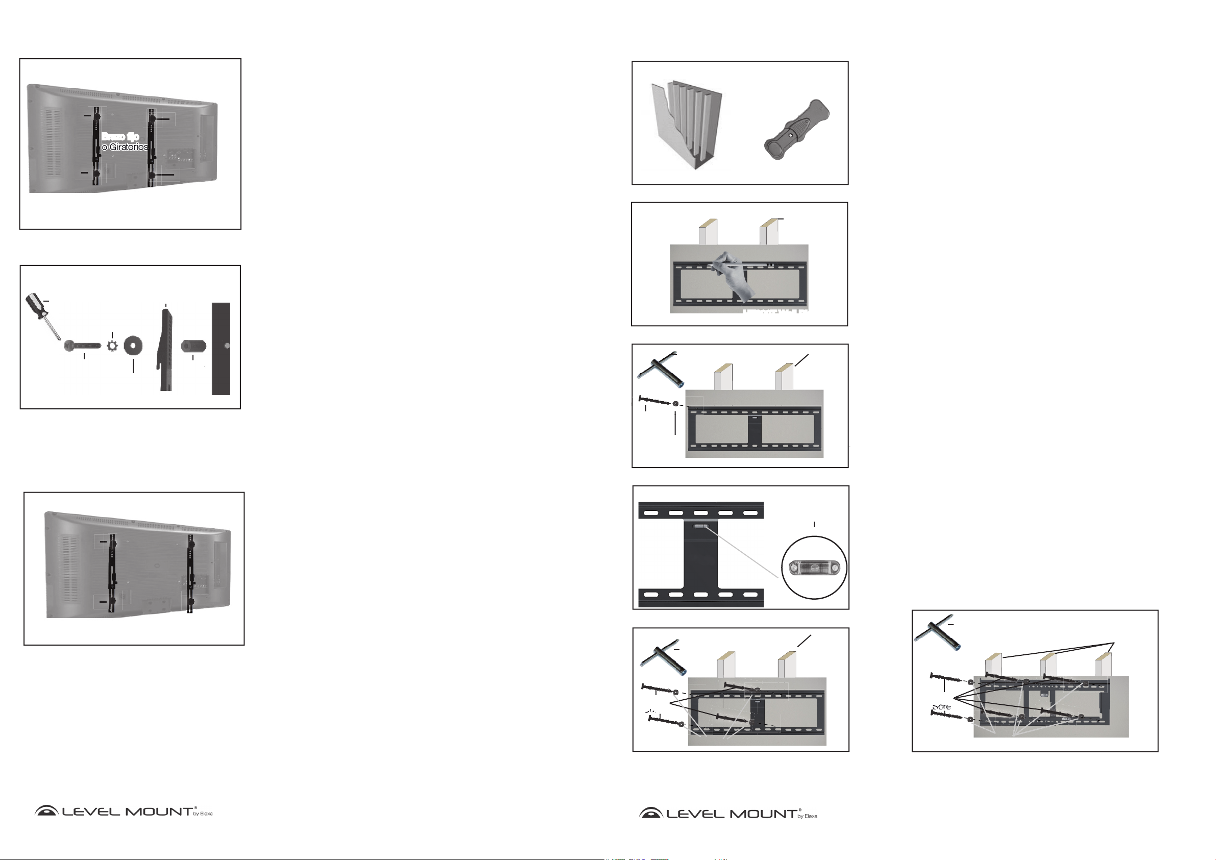
Step 4 – Attaching the Wall Plate to the Wall
Option A – If the Wall is Drywall
To attach the Wall Plate to drywall, locate two wooden studs using the Stud
Finder as shown in Figure 8. After you have determined the spot where you
believe the center of each stud to be (using the Stud Finder), hammer a small
nail into that spot far enough to confirm that you are hammering into solid wood
(and not something less dense, like particle board); remove the nail when done.
Adjust Wall Plate to desired width (if applicable). Line up the left top hole of the
Wall Plate with the stud center marked on the wall at the desired height. Then,
use a pencil to mark the wall through the top left hole in the Wall Plate over the
center of one of the studs as shown in Figure 9.
Imagen 6
Destornillador
Phillips
Arandelas de presión
M4/M5/M6/M8
Tornillo M4, M5,
M6/M8
Utilice el separador sólo en caso de que la
parte trasera de su televisor sea hueca
Brazo fijo o
giratorio
Arandelas
Imagen 7
Televisor
de pantalla
plana
Tornillo
Tornillo
Brazo fijo
o Giratorios
Televisor
de pantalla
plana
Separa dores
(Brazos Fijos Muestran)
Cuidado:
Apriete los tornillos sólo hasta que estén seguros, con
cuidado de no pasarse de rosca.
Paso 3 – Fijar los Brazos Fijos o Giratorios (sin Brazos de
Extensión) a la parte trasera de su televisor
Este paquete incluye tornillos de distintos tamaños que encontrará en las Bolsas
1 a 5. Por favor, asegúrese de utilizar el tamaño de tornillo adecuado para su
televisor.
Los televisores pequeños necesitan las siguientes herramientas: (Para la
mayoría de televisores menores de 50’’ o 127 cm)
• Tornillo M4 (Bolsa 1) o Tornillo M5 (Bolsa 2)
• Arandelas de presión M4 (Bolsa 1) o arandelas de presión M5 (Bolsa 2)
• Arandelas 20 mm x 5.5 mm x 1,0 mm (Bolsa 5)
• Es posible que necesite una arandela adicional para evitar que la cabeza del
tornillo se incruste en la parte trasera del televisor
• Brazo fijo, giratorio o voladizo
• Separador (Bolsa 5) Sólo en caso de que la parte trasera de su televisor sea
hueca.
Los televisores grandes necesitan las siguientes herramientas: (Para la mayoría
de televisores mayores de 50’’ o 127 cm)
• Tornillo M6 (Bolsa 3) o Tornillo M8 (Bolsa 4)
• Arandelas de presión M6 (Bolsa 3) o arandelas de presión M8 (Bolsa 4)
• Brazo fijo, giratorio o voladizo
• Separador (Bolsa 5) Sólo en caso de que la parte trasera de su televisor sea
hueca.
Para fijar los brazos fijos o giratorios a la parte trasera de su televisor, coloque
los 2 tornillos de cada brazo en los agujeros del brazo fijo o giratorio y apriételos
con cuidado en los agujeros de la parte trasera de su televisor. Si encuentra
resistencia, saque de inmediato el tornillo y escoja otro tamaño que entre
fácilmente y permita fijar el tornillo de manera segura. Apriete bien los tornillos a
la parte trasera de su televisor, tal y como muestran las Imágenes 7.
Cuidado:
Apriete los tornillos sólo hasta que estén seguros, con cuidado
de no pasarse de rosca.
Hex
Screw
Washer
Hex Nut
Wrench
Figure 10
Figure 11
HE800T Wall Plate
Figure 12
Hex Nut
Wrench
HE800T Wall Plate
Drywall Stud
HE800T Wall Plate
Built-in
Bubble Level/
Spirit Level
Drywall Stud
To attach the Wall Plate to the wall, drill a 4mm pilot hole where the top left
pencil mark was made. Using a Hex Nut Wrench, drive 1 Hex Screw with
Washer (Bag 6) through the one of the top left slots in the Wall Plate and through
the drywall into the stud as shown in Figure 10.
Once the top left screw is secure, adjust the Wall Plate until it is level using the
Built-in Bubble Level/Spirit Level as shown in Figure 10. With a pencil, mark
the desired location for the 3 remaining holes in the center of the two studs
identified. Drill the 3 remaining holes with a 4mm drill bit where marked.
Using a Hex Nut Wrench, drive in the additional 3 Hex Screws and Washers
(Bag 6) to secure the Wall Plate to the wall as shown in Figure 12. Screw tightly
enough to produce a strong bond, but do not over-tighten or there may be
damage to the mount or screws.
Caution: Due to the weight of the TV it is essential to mount the Wall Plate to at
least 2 wooden studs and that all 4 screws be used when mounting the
Wall Plate to the wall.
Note For DC65ADLP, ELPFW-07, HETWF, LM65ADLP,
NTPFW, LMPFW85 and HETWF– Attaching the Wall Plate
in an Extended Position
The DC65ADLP, ELPFW-07, HETWF, LM65ADLP, NTPFW & LMPFW85 mounts
can be widened to accommodate a variety of large TV sizes. The mounting holes
can expand up to 38” wide, which will reach three drywall studs. If you are using
the mount to its fullest width, it is recommended that the mount be attached to
three wood studs as shown in Figure 12A.
Hex Nut
Wrench
Figure 12A
Drywall Studs
22
www.levelmount.com
1-888-229-1459
EU: +0044 844 567 2657
©2011 Level Mount - Patents Pending
UK: 0844 567 2657
Hex
Screw
Washer
HE800T Wall Plate
7
Hex
Screw
Washer
ADLP/ELPFW-07
Wall Plate
www.levelmount.com
1-888-229-1459
EU: +0044 844 567 2657
©2011 Level Mount - Patents Pending
UK: 0844 567 2657

Assembly/Installation
Built-in Bubble Level/
Spirit Level
Concrete Wall
Concrete Anchors
Concrete Wall
Concrete Wall
Drill
Masonry Drill Bit
12mm
Concrete Wall
HE800T Wall Plate
HE800T Wall Plate
azos de exte
ns
feriores
T
or
ni
ll
o
Montaje/Instalación
Built-in Bubble Level/
Spirit Level
Figure 14
Concrete Wall
Figure 15
Figure 13
Concrete Wall
HE800T Wall Plate
Masonry Drill Bit
12mm
Drill
Concrete Wall
Concrete Anchors
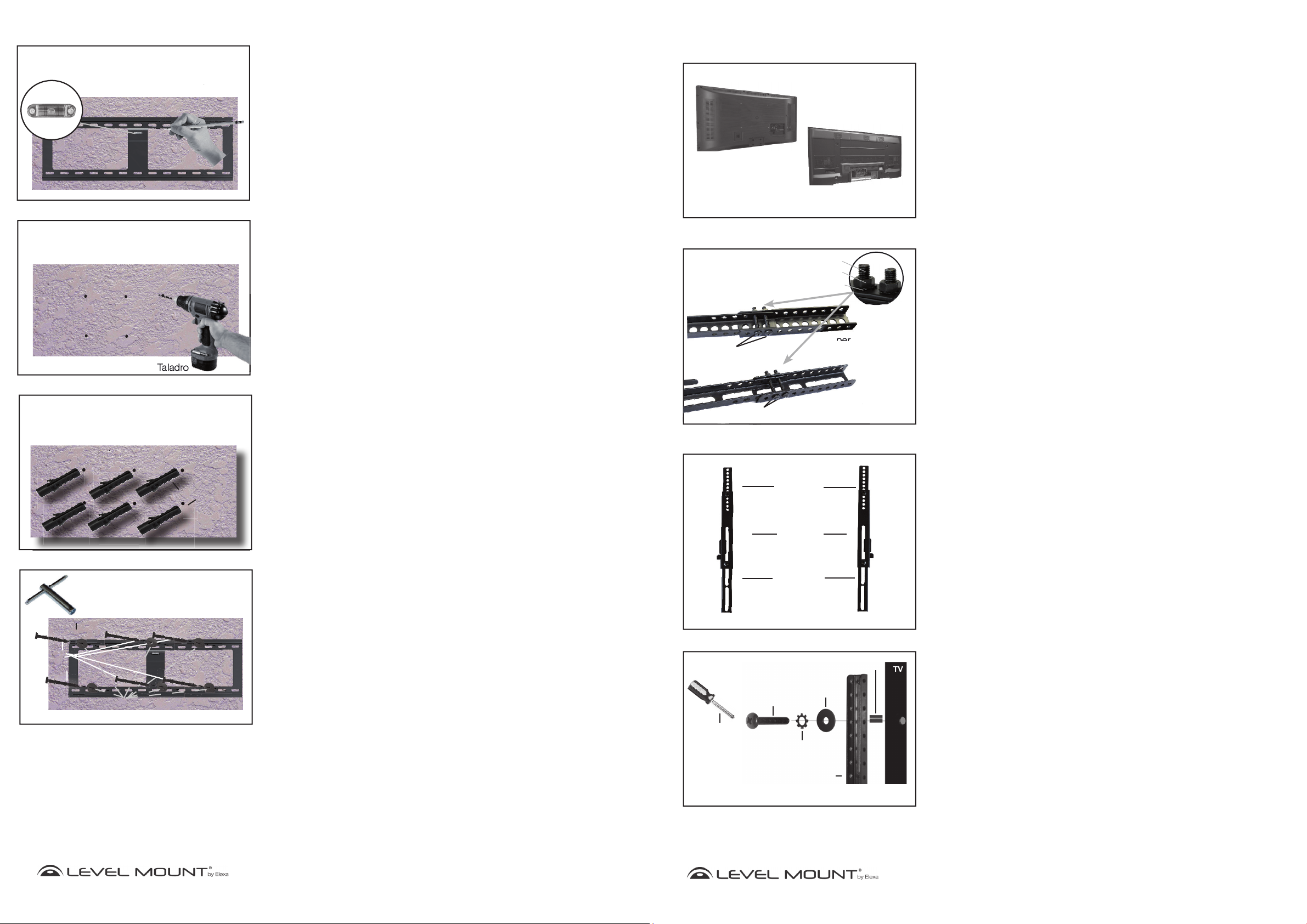
Option B – If the Wall is Concrete
To attach the Wall Plate to concrete, place the Wall Plate at the desired height.
Mark 6 holes with a pencil when the Wall Plate is level indicated by the Built-in
Bubble Level/Spirit Level as shown in Figure 13.
Set the Wall Plate to the side. Drill 6 holes into the concrete, where marked,
as shown in Figure 14. When drilling the holes for the Concrete Anchors (Bag
6) into the concrete, use an electric drill with a 12mm masonry bit.
Caution: Do not use a hammer drill, which would break out and weaken the
concrete.
Insert the 6 Concrete Anchors (Bag 6) into the holes and set them flush to the
concrete wall by tapping them in with a hammer as shown in Figure 15.
To attach the Wall Plate to the concrete wall, use a Hex Nut Wrench to drive in
6 Hex Screws and Washers (Bag 6) into each of the Concrete Anchors through
the Wall Plate as shown in Figure 16. Screw tightly enough to produce a
strong bond, but do not over-tighten or there may be damage to the mount or
screws.
Caution: Due to the weight of the TV, it is essential that all 6 screws (Bag 6)
be used when mounting the Wall Plate to the wall.
Respaldo plano
Imagen 2
M5 Tornillo
M5 Tornillo
Imagen 1
Respaldo hueco
Tuerca hexagonal
Arandela de presión
Tornillo
Brazos de extensión
superiores
Brazos de extensión
inferiores
Imagen 3
Brazos de
extensión
superiores
Brazos fijo o
giratorio
Paso 1 – Escoja el soporte correcto en función de la parte
trasera de su televisor
Antes de empezar la instalación, compruebe si la parte trasera de su televisor es
plana o hueca, tal y como muestra la Imagen 1. Si la parte trasera de su televisor es hueca, es posible que necesita utilizar los separadores (Bolsa 5), tal y como
muestran las Imágenes 4 y 6. Los separadores sirven para rellenar el hueco que
queda en la parte trasera de su televisor, de manera que el soporte quede perfectamente fijado a la parte trasera de su televisor.
Paso 2 – Instalación del Brazo de Extensión (en caso necesario)
Si los agujeros del brazo de extensión no están alineados con los agujeros de la
parte trasera de su televisor, no taladre ningún otro agujero. En lugar de ello, siga
estas instrucciones para instalar el brazo de extensión. En caso contrario, vaya
directamente al Paso 3.
Nota:
Modelo 200 o 400 no necesitan brazos de extensión. Puede utilizar los brazos de
extensión para los Modelos 600 o 900, adecuados para televisores de pantalla plana
con modelo VESA de agujero vertical mayor de 370 mm para Brazos Fijos o mayor
de 500 mm para Brazos Giratorios o Voladizos. Las instrucciones o etiquetas de su
televisor deberían especificar el tipo de modelo VESA de agujeros de su televisor.
Los televisores de pantalla plana adecuados para los soportes de pared
Paso 2a – Fijar el Brazo de Extensión a los Brazos Fijos o
Giratorios
Fije el Brazo de Extensión a los Brazos Fijos o Giratorios utilizándolas siguientes herramientas, tal y como muestra la Imagen 2:
• Tornillos M5 (Bolsa 7)
• Arandelas de presión M5 (Bolsa 7)
• Brazo de extensión
• Brazo fijo o giratorio
• Tuerca hexagonal M5 (Bolsa 7)
Ajuste el tornillo de la Imagen 2 para mover los brazos de extensión de manera que
queden alineados con los agujeros de la parte trasera de su televisor de pantalla
plana.
Paso 2b – Fijación completa del Brazo de Extensión
Hex
Screw
Figure 16
Hex Nut Wrench
Washer
Concrete Wall
HE800T Wall Plate
Brazos de
extensión
inferiores
Los 4 Brazos de Extensión deberían estar fijados de la misma forma. Una vez terminado, sus brazos fijos o giratorios junto con los brazos de extensión deberían tener el
aspecto de las Imágenes 3.
(Brazos Fijos Muestran)
Paso 2c – Fijar los Brazos de Extensión a la parte trasera del
televisor
Imagen 4
Tornillo M4,
M5 , M6 o M8
Destornillador
Phillips
Utilice el separador sólo en caso de que la parte
www.levelmount.com
8
©2011 Level Mount - Patents Pending
1-888-229-1459
EU: +0044 844 567 2657
UK: 0844 567 2657
Arandelas de presión
M4/M5/M6/M8
Brazo de extensión
trasera de su televisor sea hueca
Separadores
Arandelas
Este paquete incluye tornillos de distintos tamaños que encontrará en las Bolsas 1
a 5. Por favor, asegúrese de utilizar el tamaño de tornillo adecuado para su televisor.
Los televisores pequeños necesitan las siguientes herramientas: (Para la mayoría de
televisores menores de 50’’ o 127 cm)
• Tornillo M4 (Bolsa 1) o Tornillo M5 (Bolsa 2)
• Arandelas de presión M4 (Bolsa 1) o arandelas de presión M5 (Bolsa 2)
• Arandelas 20 mm x 5.5 mm x 1,0 mm (Bolsa 5)
• Es posible que necesite una arandela adicional para evitar que la cabeza del
tornillo se incruste en la parte trasera del televisor
• Brazo de extensión
• Separador (Bolsa 5) Sólo en caso de que la parte trasera de su televisor sea
hueca.
www.levelmount.com
21
©2011 Level Mount - Patents Pending
1-888-229-1459
EU: +0044 844 567 2657
UK: 0844 567 2657

Cómo empezar
Fixed/Tilt Arms attached to back
of TV
i
T
La
tc
WaWall
Allen Screw
Wall Plate attached to the wall
Assembly/Installation
¡CUIDADO!
!
Estos soportes de pared para TV fueron diseñados específi camente para sostener televisores
con un peso máximo de hasta 200 libras (90 kg) y con las siguientes dimensiones: 37 "85" (939,8 mm - 21519 mm) HE800T, HE885T y 26” - 85” (660,4 mm - 2159 mm) NTPFW,
LMPFW85, DC65ADLP, LM65ADLP, ELPFW-07, HETWF. El uso de este producto con un
pesado televisor que el peso máximo, o que exceda estas dimensiones, puede resultar en
lesiones personales graves y daños al equipo y propiedades.
1. No empiece a instalar el soporte de pared para televisión hasta no haber leído y comprendido las instrucciones y
advertencias de estas Instrucciones de Instalación. Si no lee, comprende completamente y sigue estas instrucciones
podría provocar lesiones personales serias o daños al equipo y propiedad. Es responsabilidad del instalador
asegurarse de que todos los componentes estén correctamente montados e instalados de acuerdo con las
instrucciones proporcionadas.
2. Si no encuentra la respuesta a una pregunta en estas Instrucciones de Instalación, revise por favor las preguntas
frecuentes que encontrará en el apartado “Consejos Útiles” de la página de detalles del Soporte de pared para
televisión, o póngase en contacto con nosotros en los teléfonos que encontrará más adelante, en el apartado
“¿Necesita ayuda?”. Si no está seguro de haber comprendido alguno de los pasos de estas instrucciones, o de su
capacidad para instalar el soporte de pared para televisión de manera segura y eficaz, debería ponerse en contacto
con un profesional.
3. Este soporte de pared para televisión contiene piezas pequeñas que podrían ser peligrosas; manténgalas fuera del
alcance de los niños.
4. El soporte de pared para televisión debe ir fijado a una estructura de madera o a los tacos perfectamente instalados
en el hormigón. No instale el soporte de pared para televisión sobre paredes de pladur. Si va a instalarlo sobre una
estructura de madera, asegúrese de poner los tornillos de fijación en el centro de la estructura. Vea las Instrucciones
del Detector de Madera, más abajo. No utilice el soporte de pared para televisión con otros dispositivos que no sean
los especificados en estas instrucciones.
5. Asegúrese de haber apretado bien todos los tornillos antes de cargar todo el peso del televisor sobre el soporte
de pared. Apriete bien los tornillos, pero sin llegar a pasarse de rosca. En cuanto vea que el tornillo está pegado
al televisor y le cuesta girar el destornillador, deténgase; de lo contrario, corre el riesgo de pasarse de rosca, lo
que podría provocar daños en el soporte de pared para televisor, reduciendo considerablemente su capacidad de
sujeción. Es posible que, de vez en cuando, necesite revisar que los tornillos están debidamente apretados.
6. Los tornillos deberían encajar completa y fácilmente en los agujeros del televisor. Si alguno de los tornillos
proporcionados no encaja bien en el sistema de montaje del soporte de pared, el instalador no deberá taladrar
agujeros en el televisor bajo ningún concepto, ni en ninguno de los componentes del soporte de pared para televisión.
Si usa tornillos de un tamaño no adecuado podría provocar daños en el televisor.
7. No levante más peso del que pueda soportar. Se necesitan al menos dos personas para levantar y colocar el televisor
sobre el soporte de pared.
8. Antes de instalar su soporte de pared, asegúrese de tener todas las partes indicadas en estas Instrucciones de
Instalación, y de que estén en buenas condiciones. No utilice nunca partes dañadas, ni intente instalar el soporte de
pared sin tener todos los elementos necesarios.
9. El instalador es responsable de escoger el lugar y la superficie más adecuados para instalar este soporte de pared,
de manera que quede perfectamente fijado a la pared. También es responsabilidad del instalador asegurarse de que
el televisor esté correcta y adecuadamente fijado en el soporte de pared, utilizando sólo los cierres y componentes
incluidos, así como de comprobar que los tornillos y cables no entren en contacto con cables, tuberías o partes de
metal dentro de la pared (puesto que podría dañar dichos elementos o provocar un cortocircuito).
10. Level Mount ha hecho todo lo posible por que estas Instrucciones de Instalación sean lo más precisas y completas posible.
Sin embargo, Level Mount no puede asegurarle que la información contenida en las mismas cubra todos los detalles,
condiciones o variaciones, ni que cubra todas los posibles incidentes relacionados con la instalación, montaje o uso de
este producto. Level Mount no garantiza, de manera expresa ni implícita, que la información contenida en este documento
sea exacta, completa o suficiente. Level Mount no se responsabiliza de ningún daño o lesión causado por el montaje,
instalación o uso indebido.
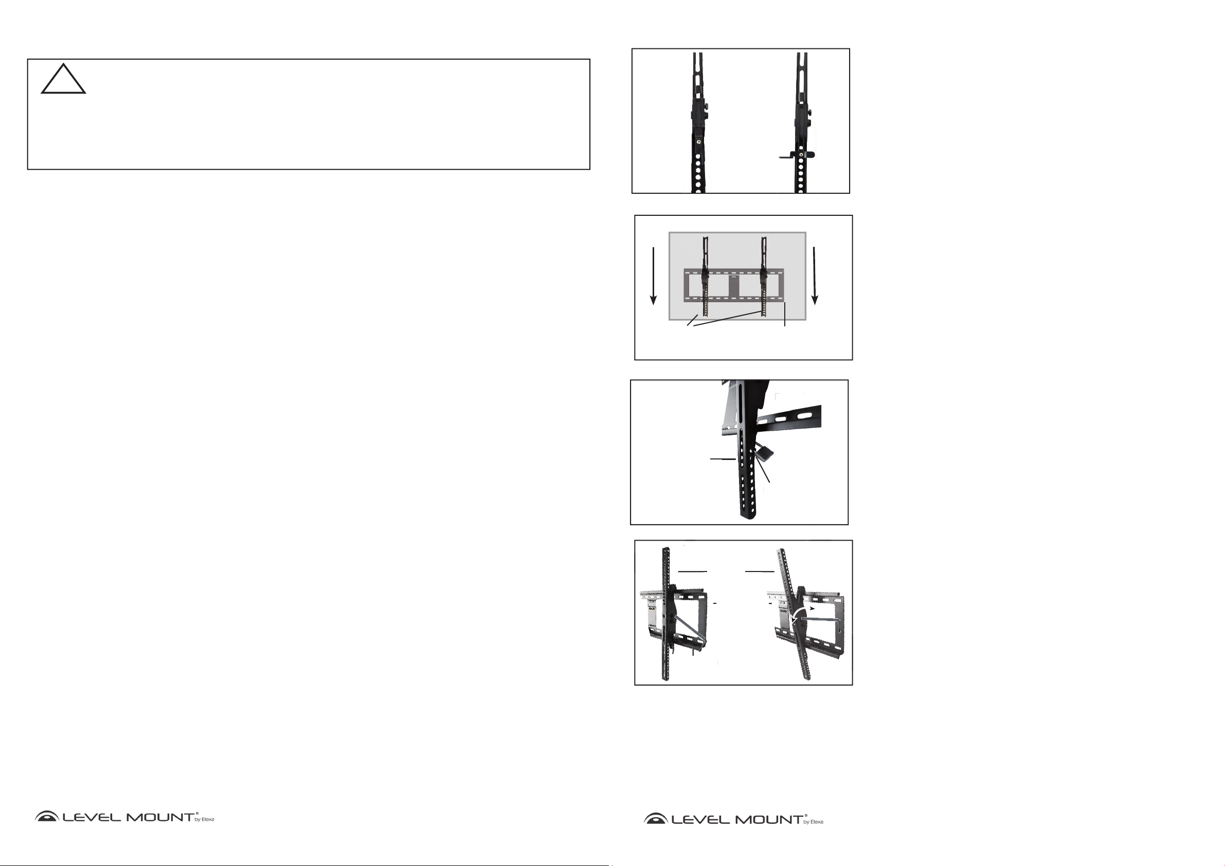
Figure 17
Fixed/
Tilt Arm
Locked
Figure 18
TV
Fixed/Tilt Arms attached to back
of TV
Wall Plate attached to the wall
Figure 19
Tilt Arm
Locking Latch
ocking
Figure 20
Tilt Arm
Allen Screw
Allen Wrench Key
Wall plate
Fixed/
T
Tilt Arm
Unlocked
Wall Plate
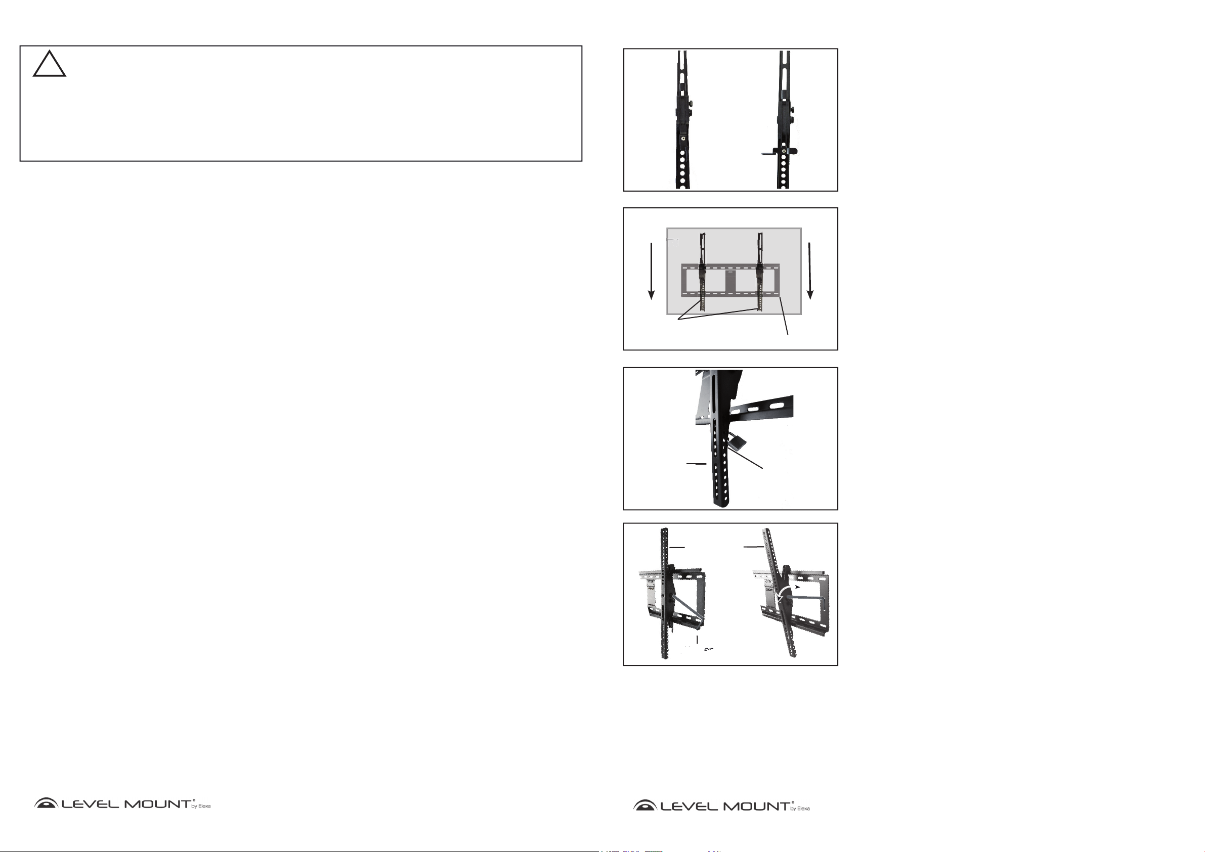
Step 5 – Mounting the TV to the Wall Plate
To mount the TV to the wall, first you will need to unlock the Fixed/Tilt Arms.
As shown in Figure 17, push the latch up to unlock and push the latch down
to lock.
After the Fixed/Tilt Arms are unlocked, two people will need to lift the TV with
the Fixed/Tilt Arms attached. Place the Fixed/Tilt Arms on the upper lip of
the Wall Plate (which has been secured to the wall as specified above) as
shown in Figure 18.
Lock the Fixed/Tilt Arms under the bottom lip of the Wall Plate by turning the
Latch as shown in Figure 17 This should be done for both Arms.
Step 6 –Locking the TV to the Wall Mount (Optional)
(HETWF, HE800T & HE885T Only)
Optional: To lock the TV to the Wall Plate, insert a lock into the Locking Latch
as shown in Figure 19. This will prevent the TV from being lifted off
of the Wall Plate.
Note: The lock is not included.
Step 7 – Tilting the TV (HETWF, HE800T & HE885T
Only)
If you choose to tilt the TV (Tilt Mount Only), pull the top of the TV away from
the wall or push the TV toward the wall.
If locking the Tilt Arm is desired, when the TV is tilted, place the 6mm Allen
Wrench Key. (Bag 6) into the Allen Screw on the Tilt Arm. Tighten clock-wise
to hold the TV in position as shown in Figure 20.
www.levelmount.com
20
©2011 Level Mount - Patents Pending
1-888-229-1459
EU: +0044 844 567 2657
UK: 0844 567 2657
9
©2011 Level Mount - Patents Pending
www.levelmount.com
1-888-229-1459
EU: +0044 844 567 2657
UK: 0844 567 2657

Besion d’aide?
Conseils Utiles
Si vous avez des questions sur l’installation de votre TV Support Mural, s’il vous plaît aller à www.
levelmount.com pour voir les tutoriels produit.
¿Qué hay en la caja?
Contacts Level Mount Service à la Clientèle
Si vous avez des questions, notre formation Service à la clientèle est heureux de vous aider, 24 heures
par jour, 7 jours par semaine, tous les jours de l’année. Contactez Level Mount Service à la clientèle
comme suit:
• Dans les États-Unis appellez: 1-888-229-1459
• En Europe appelez: +0044 844 567 2657
• Dans le Royaume-Uni appelez: 0844 567-2657
• E-mail Level Mount au www.customersupport@elexausa.com
NE PAS RETOURNER CE PRODUIT SUR LE WEBSITE OU MAGASIN DE VOUS L’AVEZ ACHETÉ
Si vous croyez que le produit est défectueux, a une partie manquante ou cassée ou ont de la diffi culté
avec l’assemblage, s’il vous plaît contacter Level Mount direcement 24 heures par jour, 7 jours par
semaine, 365 jours par an comme indiqué ci-dessus, pour une solution rapide et effi cace à votre
problème.
Outils Nécessaires
Inclus
Niveau à Bulle
Ne sot pas compris
Perceuse
Mèche per ceuse 4 mm
Mèche maçonnerie 12 mm
Marteau
Crayon
Placa de Soporte - HE800T, HE885T
Placa de Soporte - HETWF, NTPFW, LMPFW85
Brazos Fijos - 65ADLP, ELPFW-07
Placa de Soporte - 65ADLP, ELPFW-07
Bolsa 1
(4) Arandelas de
presión M4
Bolsa 3
(4) Arandelas de
presión M6
(4) Tornillos
Phillips
M4 x 12 mm
(4) Tornillos
Phillips
M4 x 20 mm
(4) Tornillos
Phillips
M4 x 30 mm
(4) Tornillos
Phillips
M6x12 mm
(4) Tornillos
Phillips
M6x24 mm
(4) Tornillos
Phillips
M6x35 mm
Soporte TV con
respaldo plano
Soporte TV con
respaldo hueco
Soporte TV con
respaldo plano
Soporte TV con
respaldo hueco
Brazo Giratorio - HETWF, HE800T, HE885T
Brazos Fijos - HETWF, NTPFW, LMPFW85
Brazos de Extensión
Bolsa 2
(4) Arandelas de
presión M5
Bolsa 4
(4) Arandelas de
presión M8
(4) Tornillos
Phillips
M5x12 mm
(4) Tornillos
Phillips
M5x20 mm
(4) Tornillos
Phillips
M5x30 mm
(4) Tornillos
Phillips
M8x16 mm
(4) Tornillos
Phillips
M8x25 mm
(4) Tornillos
Phillips
M8x40 mm
Soporte TV con
respaldo plano
Soporte TV con
respaldo hueco
Soporte TV con
respaldo plano
Soporte TV con
respaldo hueco
Clé à mollette Allen
(HETWF, HE800T,
HE885T)
10
Tournevis Phillips
Detecteur de Montants
Clé Hexagonale
www.levelmount.com
1-888-229-1459
EU: +0044 844 567 2657
©2011 Level Mount - Patents Pending
UK: 0844 567 2657
Bolsa 5
Bolsa 7
(8) Tuercas M5
(4) Separadores
Ø17,5 x Ø8,3 x 22,5 mm
(4) Separadores
Ø12,5 x Ø5,5 x 16,5 mm
Tornillos Phillips
para brazos fijos y giratorios
(8) Arandelas de presión M5
(4) Arandelas
Ø20 x Ø5,5 1,0 mm
(8) M5 x 40mm
Bolsa 6
(1)
Llave Allen
(HETWF, HE800T,
HE885T)
(6) Tornillo hexagonal para
madera
19
Ø6.3 x 75mm
(6) Tacos para hormigón
Ø12 x 60 mm
(6) Arandelas
28 mm x Ø8 mm x 1,5 mm
www.levelmount.com
1-888-229-1459
EU: +0044 844 567 2657
©2011 Level Mount - Patents Pending
UK: 0844 567 2657

¿Necesita ayuda?
Consejos útiles
Si tiene alguna duda sobre cómo instalar su soporte de pared para televisión, por favor vaya a www.
levelmount.com para ver los tutoriales del producto.
Contactar con el Servicio de Atención al Cliente Level Mount
Si tiene usted cualquier duda, nuestro departamento de Atención al Cliente le ayudará encantado las
24 horas del día, 7 días a la semana, todos los días del año. Para ponerse en contacto con el Servicio de
Atención al Cliente Level Mount:
• Desde Estados Unidos, marque: 1-888-229-1459
• Desde Europa, marque: +0044 844 567 2657
• Desde Reino Unido, marque: 0844 567 2657
• Envíe un e-mail a Level Mount a www.customersupport@elexausa.com
Quel est le contenu de la boîte?
Bras Rotatifs - HETWF, HE800T, HE885T
Plateau Mural - HE800T, HE885T
NO DEVUELVA ESTE PRODUCTO A LA TIENDA O WEB DONDE LO COMPRÓ
Si cree usted que su producto está defectuoso, que le falta una parte o tiene una parte rota, o si está
teniendo problemas para montarlo, póngase por favor directamente en contacto con Level Mount, las
24 horas del día, 7 días a la semana, 365 días al año, en los teléfonos indicados arriba, y resolveremos
su problema rápida y efi cazmente.
¿Qué herramientas necesita?
Incluidas
Nivel de burbuja
incorporadol
Nivel
Llave Allen
(HETWF, HE800T,
HE885T)
No incluidas
Taladro
Broca 4 mm
Broca para madera
12 mm
Martillo
Lápiz
Destornillador
Phillips
Detector de Madera
Plateau Mural - HETWF, NTPFW, LMPFW85
Bras Fixes - 65ADLP, ELPFW-07
Plateau Mural - 65ADLP, ELPFW-07
Sac 1
(4) M4 Joint de
verrouillage
Sac 3
(4) M6 Joint de
verrouillage
(4) M4X12 mm
Boulon Phillips
(4) M4X20 mm
Boulon Phillips
(4) M4X30 mm
Boulon Phillips
(4) M6X12 mm
Boulon Phillips
(4) M6X24 mm
Boulon Phillips
(4) M6X35 mm
Boulon Phillips
Sac 5
(4) Espaceur
Ø17,5 x Ø8,3 x 22,5mm
(4) Espaceur
Ø12,5 x Ø5,5 x 16,5mm
(4) Joint
Ø20 x Ø5,5 x 1,0mm
Arrière plat
Matériel TV
Arrière bombé
Matériel TV
Arrière plat
Matériel TV
Arrière
bombé
Matériel TV
Bras Fixes - HETWF, NTPFW, LMPFW85
Sac 2
(4) M5 Joint de
verrouillage
Sac 4
(4) M8 Joint de
verrouillage
(4) M5X12 mm
Boulon Phillips
(4) M5X20 mm
Boulon Phillips
(4) M5X30 mm
Boulon Phillips
(4) M8X16 mm
Boulon Phillips
(4) M8X25 mm
Boulon Phillips
(4) M8X40 mm
Boulon Phillips
Sac 6
(1) Clé à mollette Allen
(HETWF, HE800T,
HE885T)
(6) Attaches béton
Ø12 x 60mm
Bras de Rallonge
Arrière plat
Matériel TV
Arrière bombé
Matériel TV
Arrière plat
Matériel TV
Arrière
bombé
Matériel TV
18
Llave hexagonal
www.levelmount.com
1-888-229-1459
EU: +0044 844 567 2657
©2011 Level Mount - Patents Pending
UK: 0844 567 2657
Sac 7
(8) M5 Écrou
Boulon Phillips
(8) M5 x 40mm
(8) M5 Joint de verrouillage
(6)Vis à bois hexagonale
Ø6.3 x 75mm
11
28 mm x Ø8 mm x 1,5 mm
©2011 Level Mount - Patents Pending
(6) Joint
www.levelmount.com
1-888-229-1459
EU: +0044 844 567 2657
UK: 0844 567 2657
AVERTISSEMENTS
Bras rotatifs attaché à
l’arrière de la tv
if
T
Plateau mural fixé au mur
d
v
é
Aé Al
Vis Allen
Assemblage/Installation
ATTENTION !
!
Ce support mural pour écrans plat ont été conçus spécifi quement pour les téléviseurs avec un poids
maximal de 200 lb (90 kg) et avec les dimensions suivantes: 37” - 85” (939,8 mm - 2159 mm) HE800T,
HE885T et 26” - 85” (660,4 mm - 2159 mm) NTPFW, LMPFW85, DC65ADLP, LM65ADLP, ELPFW-07,
HETWF. L’utilisation de ce produit avec un lourd télévision que le poids maximum, ou qui dépasse ces
dimensions, peut entraîner des blessures graves et des dommages à l’équipement et des biens.
1. Ne commencez pas l’installation d’un support mural pour écrans plat sans avoir au préalable lu et compros les
instructions et avertissements qui se trouvent dans ces instructions d’installation. Le fait de ne pas lire, de ne pas
comprendre dans leur intégralité ni de suivre les instructions peut entraîner des blessures graves et des dommages à
l’équipement et aux biens situés à proximité. Il est dans la responsabilité de l’installateur de s’assurer que toutes les
parties sont correctement assemblées et installées selon les instructions fournies.
2. Si vous avez des questions qui ne semblent pas être traitées dans ces Instructions d’installation, veuillez vous rendre
sur la foire aux questions qui se trouve dans la section «Conseils utiles» de la page de détails relative au support mural
pour écrans ou contactez-nous tel qu’indiqué dans la section «Besoin d’aide» ci-dessus. Si vous n’êtes pas certain de
comprendre l’une des étapes énoncées dans ces Instructions ou si vous doutez être en mesure d’installer le support
mural pour écrans de manière sûre et sécurisée, il est préférable que vous adressiez à un entrepreneur professionnel
qualifié.
3. Ce support mural pour écrans plat contient de petites pièces qui pourraient être dangereuses en cas d’ingestion.
Veuillez garder ces pièces hors de portée des enfants.
4. Le support mural pour écrans plat doit être attaché à des montants en bois ou à des chevilles correctement insérées
dans du béton. N’installez pas le support mural pour écrans uniquement sur une cloison sèch ou sur un panneau de
plâtre. Si vous installez le support sur des mentants en bois, assurez-vous que toutes les vis de montage sont placées
au centre des montants. Reportez-vous aux Instructions afférentes au chercheur de montants, incluses ci-dessous.
N’utillsez pas le support mural pour écrans pour des appareils autres que ceux mentionnés dans ces instructions.
5. Assurez-vous que toutes les vis et tous les écrous sont serrés avant de laisser le support mural pour écrans supporter
tout le poids du téléviseur. Serrez les vis et les boulons fermement, mais sans pour autant trop forcer. Une fois que
la tête de la vis est à plat contre la télévision et qu’il devient plus difficile de tourner le tournevis, jusqu’à ce qu’il ne
tourne plus, arrêtez; sinon vous risquez de trop serrer le boulon. Un serrage excessif des vis ou des boulons pourrait
endommager le support mural pour écrans et réduire considérablement sa capacité de soutien. Il est possible que
vous soyez amené à les resserrer périodiquement.
6. Les vis doivent s’enfiler en toute facilité et complètement dans les trous de montage du téléviseur. Si l’une des vis
fournies n’entre pas dans le système du support mural pour écrans, l’installateur ne doit en aucun cas percer de trou
dans le téléviseur ou dans un composant du support mural pour écrans. L’utilisation de vis d’une taille inappropriée
peut endommager le téléviseur.
7. Ne soulevez pas plus de poids que vous ne le pouvez. Il faut au moins deux personnes pour porter et placer le
téléviseur sur le support mural pour écrans.
8. Avant l’installation, assurez-vous que toutes les pièces du support mural pour écrans mentionnées dans ces
instructions d’installation sont présentes et en bon état. N’utilisez jamais de pièces abîmées ou n’essayez jamias
d’installer le support mural pour écrans si vous n’avez pas toutes les pièces requises.
9. Il est de la responsabilité de l’installateur de choisir l’emplacement de l’installation et las surface d’appui sur laquelle
monter ce support mural pour écrans et de s’assurer que le support mural pour écrans est correctement fixé au mur. Il
est aussi de la responsabilité de l’installateur de s’assurer que le téléviseur est correctement et solidement attaché au
support mural pour écrans en utilisant seulement les attaches et les composants fournis et de vérifier que les vis et les
cordons d’alimentation ne sont pas en contact avec des fils électriques, tuyaux ou parties métalliques qui se trouvent
dans le mur (car cela pourrait endommager ces éléments ou provoquer un choc électrique).
10. Elexa Consumer Products, Inc. se sont efforcées de rendre ces Instructions d’installation précises et complètes.
Cependant, Elexa Consumer Products, Inc. ne prétend pas que les informations contenues dans les présentes
couvrent tous les détails, circonstances ou cas particuliers, ni n’anticipeent tous les imprévus possibles en rapport
avec l’installation, l’assemblage ou l’utilisation de ce produit. Elexa Consumer Products, Inc. ne garantit pas
l’exactitude, l’exhaustivité ou la suffisance des informations contenues dans ce document. Elexa Consumer Products,
Inc. n’est pas responsable de tout dommage ou préjudice causé par un mantage, assemblage incorrect, une
installation ou utilisation incorrecte.
Figure 17
Bras rotatif
Verrouillé
Figure 18
TV
Bras rotatifs attaché à
l’arrière de la tv
Figure 19
Bras rotatifs
Figure 20
Bras rotatif
Vis Allen
Clé Allen
Bras rotatif
Déverrouillé
Plateau mural fixé au mur
Plateau mural
Levier de
evier
verrouillage
errouill
Étape 5 – Montage du téléviseur à la plaque murale
Pour monter le téléviseur à la plaque murale, vous devez d’abord déverrouiller les
bras inclinables. Comme illustré en Figure 17, soulevez le loquet pour déverrouiller
et baissez-le pour verrouiller.
Une fois que les bras inclinables sont déverrouillés, il n’y aura besoin que de deux
personnes pour porter le téléviseur avec les bras inclinables attachés. Placez les
bras inclinables sur la lèvre supérieure de la plaque murale (qui a été fixée au mur
comme décrit ci-dessus) comme montré en Figure 18.
Verrouillez les bras inclinables sous la lèvre inférieure de la plaque murale en
tournant le loquet comme dans la Figure 17. Cela devrait être fait sur les deux bras
inclinables.
Étape 6 – Verrouiller le téléviseur au support mural (en
option)
En option : Pour verrouiller le téléviseur au support mural, veuillez insérer un
cadenas au loquet de verrouillage comme montré en Figure 19. Cela
évitera que le téléviseur soit soulevé ou tiré d’un côté de la plaque
murale ou de l’autre.
Remarque : Le cadenas n’est pas inclut.
(Seulement HETWF, HE800T & HE885T)
Étape 7 – Incliner le téléviseur
(Seulement
Si vous décidez d’incliner le téléviseur, éloignez le haut du téléviseur du mur ou
poussez-le vers le mur.
Si vous désirez verrouiller le bras inclinable, lorsque le téléviseur est incliné,
placez la clé Allen de 6 mm (Sachet 6) dans la vis Allen qui se trouve sur la barre
inclinable. Serrez dans le sens des aiguilles d’une montre pour que le téléviseur
reste en position comme montré en Figure 20.
HETWF, HE800T& HE885T)
www.levelmount.com
12
©2011 Level Mount - Patents Pending
1-888-229-1459
EU: +0044 844 567 2657
UK: 0844 567 2657
17
©2011 Level Mount - Patents Pending
www.levelmount.com
1-888-229-1459
EU: +0044 844 567 2657
UK: 0844 567 2657

Assemblage/Installation
Mur béton
Mur béton
Plateau mural
Mur béton
Perceuse
Mèche de maçonnerie
12 mm
Attaches béton
Mur béton
Hexagonale
Vis
hexagonale
Joint
Plateau mural
ge
fé
rieu
r
lo
n
Boulon
p
Assemblage/Installation
Niveau à
bulle Intégré
Figure 14
Mèche de maçonnerie
12 mm
Figure 15
Figure 13
Mur béton
Plateau mural
Mur béton
Perceuse
Mur béton
Attaches béton
Option B – Si le mur est en béton
Pour fixer la plaque murale sur du béton, installez la plaque murale à la hauteur
désirée. Marquez les six trous au crayon une fois que la plaque murale est au
bon niveau en utilisant le niveau à bulle d’air intégré comme montré en Figure13.
Mettez la plaque murale de côté. Percez six trous dans le béton, à l’endroit
des marques, comme montré dans la Figure 13. Lorsque vous percez les trous
pour les chevilles pour béton (Sachet 6) dans le béton, utilisez une perceuse
électrique avec un foret à béton de 12 mm.
Attention : n’utilisez pas de perceuse à percussion, qui pourrait abîmer ou
affaiblir le béton.
Insérez les six chevilles pour béton (Sachet 6) dans les trous et encastrez-les
dans le mur en béton en tapant dessus avec un marteau comme montré dans la
Figure 15.
Pour attacher la plaque murale au mur en béton, utilisez une clé pour écrou
hexagonal pour visser six écrous hexagonaux avec rondelle (Sachet 6) dans
chaque cheville pour béton à travers la plaque murale comme montré dans la
Figure 16. Vissez suffisamment pour que l’attache soit solide, mais ne serrez
pas trop fort, car cela pourrait abîmer la monture ou les vis.
Attention : compte tenu du poids du téléviseur, il est essentiel d’utiliser les 6 vis
(Sachet 6) lors du montage de la plaque murale sur le mur.
Arrière plat
Figure 2
M5 Boulon
M5 Boulon
Figure 1
Arrière Concave
Boulon
Écrou Hexagonal
Rondelle Frein
Bras de Rallonge
Supérieur
Bras de Rallonge
Inférieur
Figure 3
Bras de rallonge supérieur
Bras Fixe/
Inclinable
Étape 1 – Choix du matériel approprié en
fonction de la surface arrière du téléviseur
Avant de commencer l’installation, il faut déterminer si l’arrière
du téléviseur est plat, concave ou convexe tel qu’illustré en
Figure 1. Si votre téléviseur a une surface arrière convexe ou
concave, vous pourriez avoir besoin d’utiliser les entretoises
(Sachet 5) comme illustrées dans la Figure 5 ou dans la Figure
6. L’entretoise est utilisée pour remplir la zone convexe ou
concave du téléviseur de manière à ce que le support du
téléviseur soit entièrement supporté et s’encastre avec l’arrière
du téléviseur.
Étape 2 – Installation du bras de rallonge (si
nécessaire)
Si les trous des bras fixes ou inclinables ne sont pas alignés
avec les trous qui se trouvent à l’arrière du téléviseur, ne percez
pas. Au lieu de cela, suivez ces instructions pour l’installation
du bras de rallonge. Sinon, passez à l’étape 3.
Étape 2a – Attacher le bras de rallonge aux
Bras Fixe ou Inclinable.
Attachez le bras de rallonge aux Bras Fixe ou Inclinable en
utilisant le matériel suivant comme montré dans la Figure 2 :
• Boulons M5 (Sachet 7)
• Rondelle frein M5 (Sachet 7)
• Bras de rallonge
• Bras Fixe ou Inclinable
• Écrou M5 (Sachet 7)
Ajustez le boulon de la Figure 2 pour déplacer le bras de rallonge
afin qu’il soit aligné avec les trous qui se trouvent à l’arrière du
téléviseur.
Étape 2b – Fixation de bras de rallonge
complète
Vis
hexagonale
Hexagonale
Clé
Figure 16
Joint
Mur béton
Plateau mural
16
www.levelmount.com
1-888-229-1459
EU: +0044 844 567 2657
©2011 Level Mount - Patents Pending
UK: 0844 567 2657
Bras de rallonge inférieur
Figure 4
M4, M5, M6, M8
Bras de rallonge
Entretoise
Rondelle frein
M4, M5, M6,
M8 Boulon
Tournevis Phillips
Rondelle
Seulement si la surface arrière du téléviseur est
convexe ou concave.
Les 4 bras de rallonge doivent être attachés de la même manière.
Une fois la fixation complète, vos bras fixes, inclinables ou
cantilever, avec les bras de rallonge attachés, doivent ressembler
à la photo de la Figure 3.
Étape 2c – Attacher les bras de rallonge à
l’arrière du téléviseur
Ce paquet contient des boulons de longueur variable (Sachets 1
à 5). Veuillez utiliser le boulon de longueur appropriée pour votre
téléviseur.
Vous aurez besoin du matériel suivant pour les petits téléviseurs:
(c’est à dire, des téléviseurs de moins de 127 cm – 50 po)
• Boulons M4 (Sachet 1) ou boulons M5 (Sachet 2)
• Rondelle frein M4 (Sachet 1) ou rondelle frein M5 (Sachet 2)
• Rondelle 19,05 x 5,3 x 1,2 mm (Sachet 5)
• Vous pourriez avoir besoin d’une rondelle supplémentaire afin
d’empêcher que le la tête du boulon s’encastre dans l’arrière
du téléviseur
• Bras de rallonge
• Entretoise (Sachet 5) – uniquement si la surface arrière du
téléviseur est convexe ou concave
www.levelmount.com
13
©2011 Level Mount - Patents Pending
1-888-229-1459
EU: +0044 844 567 2657
UK: 0844 567 2657

Assemblage/Installation
7
Plaque mural
Plaque mural
Hexagonale
Plaque mural
go
go
go
go
gogggg
na
Joint
Plaque mural
Hexagonale
Hexagonale
Plaque mural
Joint
Assemblage/Installation
Figure 5
Écran Plat
Boulon
Bras Fixes ou
Inclinable
Boulon
(Bras fixes montré)
Figure 6
M4, M5, M6, M8
Rondelle frein
M4, M5, M6,
M8 Boulon
Tournevis Phillips
Rondelle
Seulement si la surface arrière du téléviseur est
convexe ou concave.
Écran Plat
Boulon
Boulon
Figure 7
Bras Fixes
ou Inclinable
Bras de Rallonge
Supérieur
Bras de Rallonge
Inférieur
Bras Inclinable
Entretoise
Bras de Rallonge
Supérieur
Étape 2c – Attacher les bras de rallonge à
l’arrière du téléviseur (Continuer)
Le matériel suivant est nécessaire pour les grands téléviseurs:
(c’est-à-dire, des téléviseurs de plus de 127 cm – 50 po)
• Boulons M6 (Sachet 3) ou boulons M8 (Sachet 4)
• Boulon M6 (Sachet 3) ou boulon M8 (Sachet 4)
• Bras de rallonge
• Entretoise (Sachet 5) Seulement si la surface arrière du
téléviseur est convexe ou concave.
Pour attacher les bras fixes/inclinables à l’arrière du téléviseur,
placez les deux boulons de chaque bras à travers les trous des
bras fixes/inclinables et vissez soigneusement les boulons dans
les trous qui se trouvent à l’arrière du téléviseur. S’il y a une
résistance, retirez le boulon immédiatement et choisissez un
boulon de bonne taille qui permet un ajustement solide et sûr.
Serrez les boulons a l’arrière du téléviseur sans trop forcer tel
qu’illustré en Figure 5
Attention : Serrez les boulons jusqu’à ce q’uils soient
fermement fixés, sans trop forcer..
Étape 3 – Attacher les bras Bras Fixe ou
Inclinable (sans Bras de rallonge) à
l’arrière du téléviseur
Ce paquet contient des boulons de longueur variable (Sachets
1 à 5). Veuillez utiliser le boulon de longueur appropriée pour
votre téléviseur.
Vous aurez besoin du matériel suivant pour les petits téléviseurs:
(c’est à dire, des téléviseurs de moins de 127 cm – 50 po)
(Figure 7)
• Boulons M4 (Sachet 1) ou boulons M5 (Sachet 2)
• Rondelle frein M4 (Sachet 1) ou rondelle frein M5 (Sachet 2)
• Rondelle 19,05 x 5,3 x 1,2 mm (Sachet 5)
• Vous pourriez avoir besoin d’une rondelle supplémentaire
afin d’empêcher que le la tête du boulon s’encastre dans
l’arrière du téléviseur
• Bras Fixe ou Inclinable
• Entretoise (Sachet 5)- uniquement si la surface arrière du
téléviseur est convexe ou concave
Le matériel suivant est nécessaire pour les grands téléviseurs:
(c’est-à-dire, des téléviseurs de plus de 127 cm – 50 po) (Figure
7)
• Boulons M6 (Sachet 3) ou boulons M8 (Sachet 4)
• Boulon M6 (Sachet 3) ou boulon M8 (Sachet 4)
• Bras Fixe ou Inclinable
• Entretoise (Sachet 5) - uniquement si la surface arrière du
téléviseur est convexe ou concave
Pour attacher les bras fixes/inclinables à l’arrière du téléviseur,
placez les deux boulons de chaque bras à travers les trous des
bras fixes/inclinables et vissez soigneusement les boulons dans
les trous qui se trouvent à l’arrière du téléviseur. S’il y a une
résistance, retirez le boulon immédiatement et choisissez un
boulon de bonne taille qui permet un ajustement solide et sûr.
Serrez les boulons a l’arrière du téléviseur sans trop forcer tel
qu’illustré en Figure 7
Figure 8
Localisateur de montants
Cloison sèche avec attaches exposées
Figure 9
Attache
cloison sèche
Plaque mural
Figure 10
Clé
Hexagonale
Joint
Vis
Hexagonale
Attache cloison
sèche
Plaque mural
Figure 11
bulle Intégré
Plaque mural
Figure 12
Clé
Hexagonale
Vis
hexagonale
Joint
Attache cloison
sèche
Plaque mural
Niveau à
Étape 4 – Percement de trous dans le mur pour la
plaque murale
Option A – Si le mur est une cloison sèche
Pour attacher la plaque murale à une cloison sèche, localisez deux montants
en bois avec le localisateur de montants comme montré dans la Figure 4. Une
fois que vous avez déterminé l’endroit où vous pensez que le centre de chaque
montant se trouve (en utilisant le localisateur de montants), enfoncez un petit
clou à cet endroit assez profondément de manière à ce que vous puissiez
confirmer être en train d’enfoncer dans du bois massif (et non pas dans
quelque chose de moins dense comme un panneau de particules), puis retirez
le clou une fois que c’est fait.
Alignez le trou en haut à gauche de la plaque murale avec le centre du montant
marqué sur le mur et la hauteur désirée. Ensuite, utilisez un crayon pour faire
une marque sur le mur à travers le trou en haut à gauche de la plaque murale
sur le centre d’un des montants comme montré sur la Figure 9.
Pour attacher la plaque murale au mur, percez un avant-trou de 3 mm où la
marque a été faite au crayon. En utilisant la clé pour écrou hexagonal, vissez
un écrou hexagonal avec rondelle (Sachet 6) dans l’un des trous en haut
à gauche de la plaque murale et à travers la cloison sèche jusque dans le
montant comme montré dans la Figure 10.
Une fois la vis en haut à gauche solidement vissée, ajustez la plaque murale
jusqu’à ce qu’elle soit au bon niveau en utilisant le niveau à bulle d’air intégré/
comme montré en Figure 11. Marquez au crayon l’emplacement désiré des
trois trous restants au centre des deux montants identifiés. Percez les trois
trous restants avec une mèche de 3 mm aux endroits indiqués.
En utilisant une clé pour écrou hexagonal, vissez les trois écrous hexagonaux
avec rondelle supplémentaires (Sachet 6) pour fixer la plaque murale au mur
comme montré dans la Figure 12. Vissez suffisamment pour que l’attache soit
solide, mais ne serrez pas trop fort, car cela pourrait abîmer la monture ou les
vis.
Attention : du fait du poids du téléviseur, il est essentiel de fixer la plaque
murale sur au moins deux montants en bois et que les quatre vis
soient utilisées lors du montage de la plaque murale sur le mur.
Note pour les DC65ADLP, ELPFW-07, HETWF,
LM65ADLP, NTPFW, LMPFW85 et HETWF– Fixation de la
Plaque Murale dans une position étendue.
Les DC65ADLP, ELPFW-07, HETWF, LM65ADLP, NTPFW & LMPFW85 Plaques
murale peut être élargi pour accueillir une variété de tailles de télévision de
grande taille. Les trous de montage peut étendre jusqu’à 38 “de large, qui
atteindra trois goujons de cloison sèche. Si vous utilisez le support à sa pleine
largeur, il est recommandé que la monture soit attaché à trois poteaux de bois
comme le montre la figure 12A.
Clé
Hexagonale
Figure 12A
Attache cloison
sèche
(Bras fixes montré)
Bras de Rallonge
Inférieur
Attention : Serrez les boulons jusqu’à ce q’uils soient fermement
fixés, sans trop forcer.
14
www.levelmount.com
1-888-229-1459
EU: +0044 844 567 2657
©2011 Level Mount - Patents Pending
UK: 0844 567 2657
Vis
hexagonale
15
Joint
Plaque mural
©2011 Level Mount - Patents Pending
www.levelmount.com
1-888-229-1459
EU: +0044 844 567 2657
UK: 0844 567 2657
 Loading...