


English
Installation Instructions
Motorized Full Motion LCD/Plasma Wall Mount - SMM-08, LM42SM, DC42SM
!
CAUTION
specifi cally to hold LCD TV’s 10” - 42” and a
maximum weight of up to 100 lbs. Using this
product with a TV heavier than the maximum
weight may result in injury.
DO NOT RETURN THIS PRODUCT TO THE
STORE OR WEB SITE YOU PURCHASED IT
FROM!
IF YOU BELIEVE THIS MOUNT IS DEFECTIVE,
HAS MISSING OR BROKEN PARTS, OR IF
YOU ARE HAVING DIFFICULTY INSTALLING
THIS MOUNT TO YOUR WALL OR FITTING
YOUR TV, PLEASE CONTACT OUR COMPANY,
LEVEL MOUNT, DIRECTLY.
Dial 1 888 229 1459 or email us at
CustomerSupport@ElexaUSA.com any time of
the day or night for a quick and efficient solution
to your problem.
Our trained Customer Service Department is
open 24 hours a day, 7 days a week, every day
of the year and is prepared to assist you in both
English and Spanish.
Please also visit our Web Site at www.
LevelMount.com for assistance.
CAUTION:
Installer must make sure the LCD/Plasma
Wall Mount is properly and securely attached
and that appropriate fasteners are used. It is
the responsibility of the installer to verify that
the mount is anchored properly to the wall.
PLEASE NOTE: THE MOUNT MUST BE
ATTACHED TO WOOD STUDS OR TO
PROPERLY INSTALLED LEAD ANCHORS IN
MASONRY OR CONCRETE. DO NOT MOUNT
ONLY TO DRYWALL.
Before installing, check to make sure all parts
of the mount are included.
Make sure never to exceed the maximum
weight of 100 lbs.
Make sure all screws and bolts are tightened
before allowing Wall Mount to bear the full
weight of the LCD/plasma display.
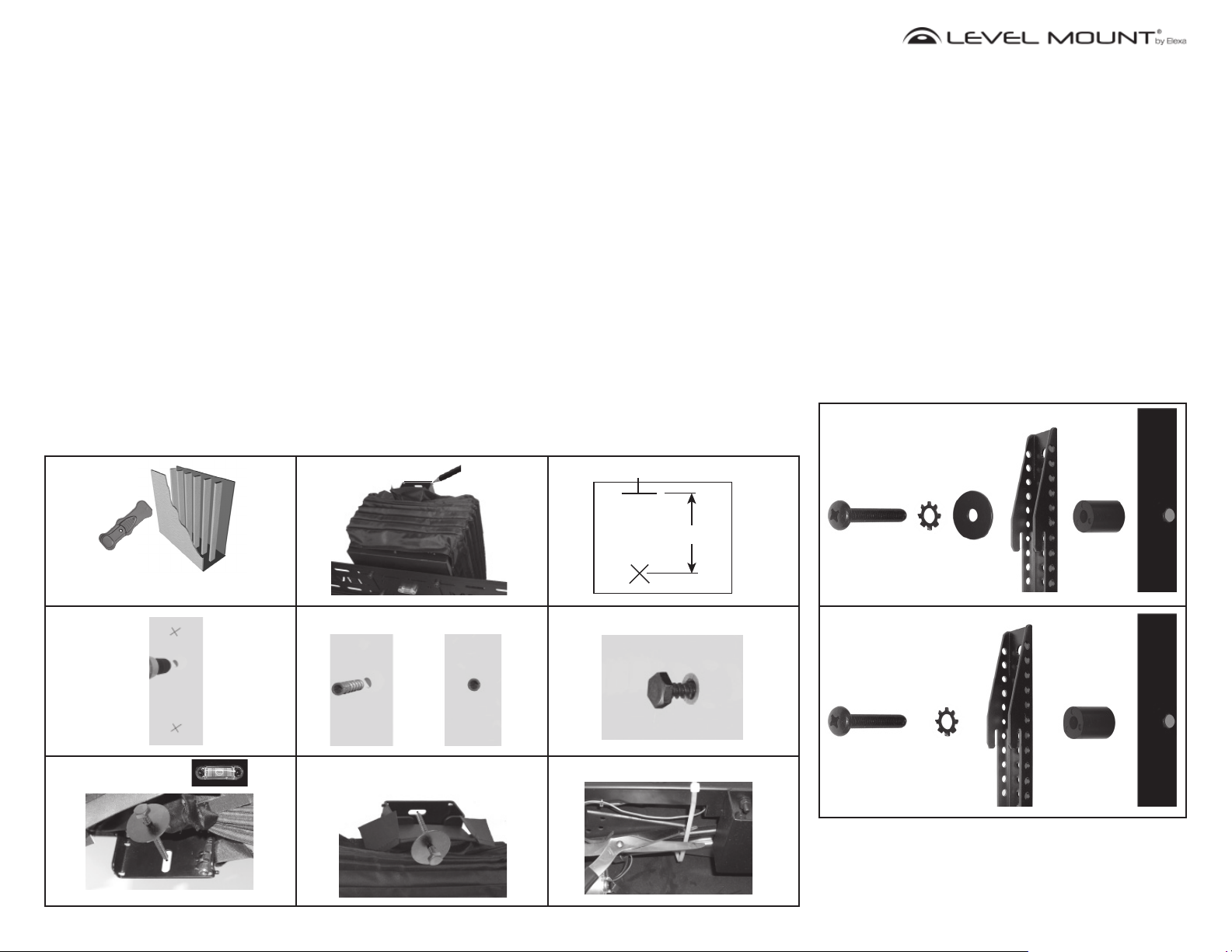
Features:
• Integrated Bubble Level
• Durable Steel Construction
• Easy 2 Piece Mounting
• Tilts 15 degrees, Pans 30 degrees
• Locking Lever
• Stud Finder Included
This wall mount was designed
Stud Finder
LCD/Plasma
Mounting Arm
SMM-08
Mount
Remote
Control
AC
Adapter
Installation
Hardware
Mounting Hardware Included:
Bag Ref Description QTY
A M4X12/Bolts 4
B M4X20/Bolts 4
1
C M4X30/Bolts 4
D M4 Lock Washers 4
E M5X30/Bolts 4
F M5X12/Bolts 4
2
G M5X20/Bolts 4
H M5 Lock Washers 4
I M6X35/Bolts 4
J M6X24/Bolts 4
3
K M6X12/Bolts 4
L M6 Lock Washers 4
M M8x40 bolts 4
4
N M8X25/Bolts 4
O M8 Lock Washers 4
P M4/M5 Spacers 4
5
Q M6/M8 Spacers 4
R WashersΦ20XΦ5.5X1.2 4
S Lag Bolts 3
T WashersΦ38XΦ6.8X1.5 3
6
U Hex wrench 1
V Concrete Anchor
Φ12.5X44.5
Tools required for attachment to stud:
Hex Wrench (Included)•
Stud finder (Included)•
Electric drill•
3/16” Wood Drill Bit•
Tools required for attaching to concrete:
Hex Wrench (Included)•
Electric drill •
1/2’’ (12 mm) Masonry Bit•
www.LevelMount.com
1-888-229-1459
©2008 Level Mount
Patents Pending
3
Installation Instructions:
Attaching Wall Mount to Studs:
Locate a proper place to mount by using a quality stud finder 1.
(Figure 1). Mark center of stud. It is recommended that the
center of the stud be used and that a nail be used to verify that
a stud has been located.
Gently pull back vinyl cover at top of backplate to expose 2.
plate. Hold mount up to wall and mark wall at top of mount
backplate at desired height. (Figure 2) (Set mount aside after
marking)
Measure down stud from top of plate 2-5/8” and mark for first 3.
screw. (Figure 3) and drill (3/16” x 3”) deep pilot hole into wall
at mark
Using Hex Key (Provided) screw (1) Hex Screw into pilot hole 4.
leaving 1/8” gap to wall.
Carefully cut cable tie holding motorized plate. (Figure 9)5.
Place mount on screw using butterfly hole (second hole from 6.
top).
Level mount using Bubble Level and drill 2nd (3/16” x 3”) deep 7.
pilot hole through bottom hole in backplate. (Figure 7)
Using Hex Key attach 2nd screw/washer combination (Do Not 8.
Overtighten) (Figure 7)
Drill 3rd (3/16” x 3”) deep pilot hole through hole through top 9.
hole in backplate. (Figure 8)
Attach 3rd screw/washer combination (Do Not Overtighten) 10.
(Figure 8)
Using Hex Key tighten first screw (Do Not Overtighten)11.
Figure 1 Figure 2 Figure 3
Top of Mount
Attaching Wall Mount to Concrete:
Gently pull back vinyl cover at top of backplate to expose 1.
plate. Hold mount up to wall and mark wall at top of mount
backplate at desired height. (Figure 2) (Set mount aside after
marking)
Measure down from top of plate 2-5/8” and mark for first screw. 2.
(Figure 3)
Drill (1/2” x 3-1/8”) deep hole into wall at mark (Figure 4)3.
Insert Concrete Anchor flush with wall. (Figure 5)4.
Using Hex Key (Provided) screw (1) Hex Screw into concrete 5.
anchor leaving 1/8” gap to wall. (Figure 6)
Place mount on screw using butterfly hole (second hole from 6.
top).
Level mount using Bubble Level mark two remaining mounting 7.
holes on wall.
Remove mount and drill at marks (1/2” x 3-1/4”) deep holes.8.
Insert concrete anchors until flush with wall.9.
Carefully cut cable tie holding motorized plate. (Figure 9)10.
Reinstall mount on single screw. 11.
Attach 2nd and 3rd screw/washer combination (Do Not 12.
Overtighten)
Using Hex Key tighten first screw (Do Not Overtighten)13.
Attaching LCD/Plasma to Mounting Arms:
Determine Correct bolt to attach TV to Mounting Arm.1.
Caution: Carefully thread the bolt into the back
of your LCD to determine which bolt is to be used. If
there is any resistance remove the bolt immediately.
Select longest bolt that can be fully threaded into TV.
Never place LCD/Plasma screen face
down on any surface to prevent scratching.
DO NOT OVERTIGHTEN BOLTS WHEN INSTALLING ARMS
ON TELEVISION.
Install mounting arm to TV with Bolt, Lock Washer, and Flat 2.
Washer for M4 or M5 Bolts. (Figure 10)
Install mounting arm to TV with Bolt and Lock Washer3. for M6
or M8 Bolts. (Figure 11)
Figure 10
M4 and M5 Bolts
Bags 1 or 2
Top of Mount Mark
Please Refer to Stud Finder
Instruction Manual
Figure 4 Figure 5 Figure 6
U
T
S
Figure 7 Figure 8 Figure 9
Top of Mount
S
T
Bottom of Mount
2-5/8”
Figure 11
M6 and M8 Bolts
Bags 3 or 4
(USE SPACER
ONLY IF
NEEDED)
(USE SPACER
ONLY IF
NEEDED)
www.LevelMount.com
1-888-229-1459
©2008 Level Mount
Patents Pending
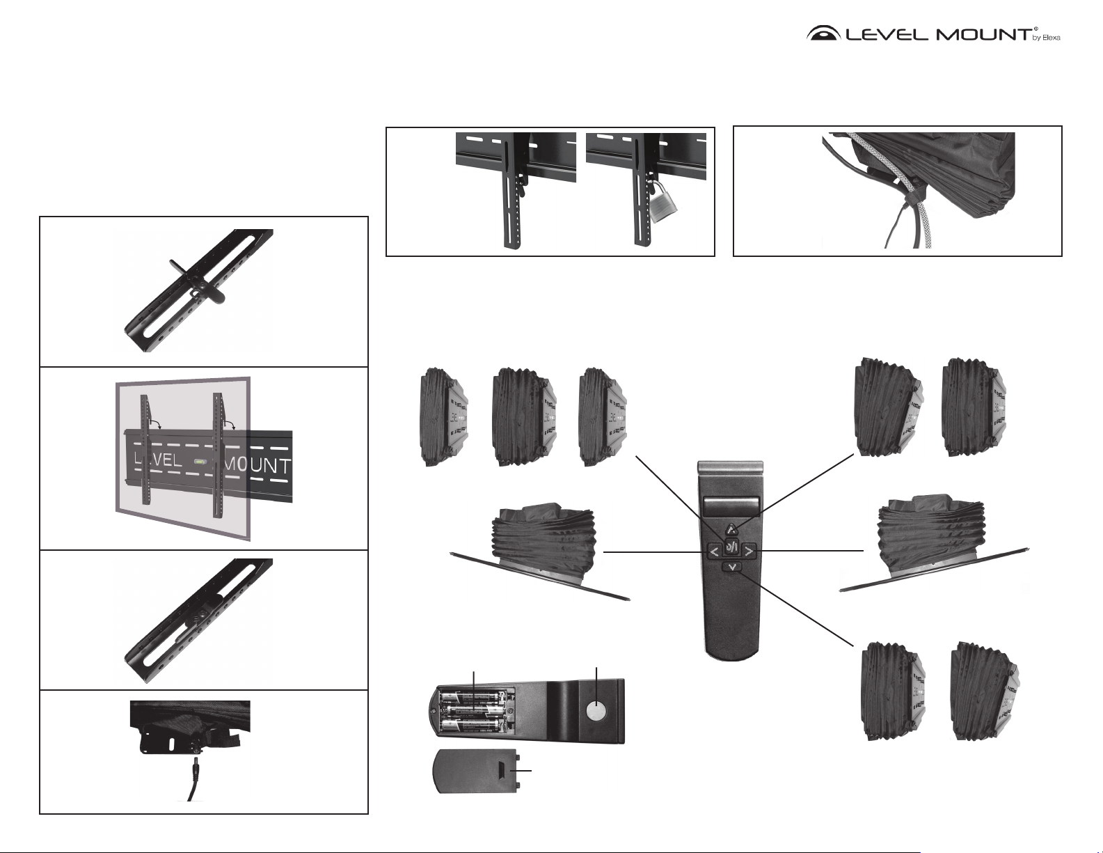
Attaching Mounting Arms to Wall Mount:
Place locking levers on mounting arm in horizontal position 1.
(Figure 12),
Slide arms with TV over mounting plate (Figure 13).2.
Rotate Locking Levers to vertical position (Figure 14) to 3.
secure TV to mount.
TV may be moved from left to right for final location.4.
Plug in AC power adapter to bottom of mount and wall outlet. 5.
(Figure 15)
Figure 12
Locking TV to Mount:
With locking lever in locked position, add padlock to prevent 1.
theft or accidental movement of lever. (Figure 16)
Figure 16
Using Remote Control:
Press center button once to extend mount from wall1.
Adjust mount as desired.2.
Press center button again to return mount to seated position 3.
(mount will realign before moving back to wall)
Using Cord Management:
Use Velcro strap at bottom of mount to secure all wires and 1.
cables. Make sure to leave enough wire above strap to allow
free movement of mount! (Figure 17)
Figure 17
Press top button to tilt mount up. (mount will
not tilt upward from parallel to wall)
Figure 13
Figure 14
Figure 15
Side View
Top View
Press left button to pan mount left.
AAA x 3
Back of Remote
Magnetic Holder
Battery Cover
Note: Photos taken without TV
or mounting arms installed
Remote
Control
Side View
Top View
Press right button to pan mount right.
Side View
Press bottom button to tilt mount down.
www.LevelMount.com
1-888-229-1459
©2008 Level Mount
Patents Pending

Español
Instrucciones de Instalación
Motion Motorizada íntegro LCD / Plasma Wall Mount - SMM-08, LM42SM, DC42SM
!
PRECAUCIÓN
pared, fue diseñado específi camente para
mantener LCD TV 10 “- 42” y un peso máximo
de hasta 100 libras. El uso de este producto
con un peso superior a la televisión el peso
máximo puede resultar en lesiones.
NO DEVUELVA ESTE PRODUCTO A LA TIENDA
O SITIO WEB EN EL QUE LO COMPRÓ.
SI EL SOPORTE ESTÁ DEFECTUOSO,
PRESENTA PARTES ROTAS O LE FALTAN
PIEZAS; SI TIENE DIFICULTADES PARA
MONTARLO EN LA PARED O PARA
COLOCAR EN ÉL SU TELEVISOR, PÓNGASE
EN CONTACTO DIRECTAMENTE CON LA
EMPRESA LEVEL MOUNT.
Si desea obtener una solución rápida y eficaz para su problema, llame al número de
teléfono 1 888 229 1459 o envíenos un
mensaje de correo electrónico a la dirección
CustomerSupport@ElexaUSA.com, a cualquier hora del día o de la noche.
Nuestro personal del departamento de atención al cliente es muy competente, está disponible de manera permanente durante todo
el año y le atenderán tanto en inglés como
en español.
Si desea obtener más información, acuda a
nuestro sitio Web www.LevelMount.com
PRECAUCIÓN:
Instalador debe asegurarse de que el LCD /
Plasma Wall Mount es adecuada y segura y
de que los sujetadores se utilizan. Es responsabilidad de la instalación para verificar
que el montaje está correctamente anclado
a la pared.
POR FAVOR TENGA EN CUENTA: EL
MONTAJE SE DEBE CONECTAR A LA
MADERA O POSTES PARA CONDUCIR
CORRECTAMENTE INSTALADO EN LOS
ANCLAJES DE MAMPOSTERÍA O DE
HORMIGÓN. NO SÓLO PARA MONTAJE EN
PARED SECA.
Antes de la instalación, asegúrese de que
todas las partes del montaje se incluyen.
Asegúrese de no superar nunca el peso
máximo de 100 libras.
Asegúrese de que todos los tornillos y pernos son más estrictas antes de permitir el
montaje en pared para soportar todo el peso
de la pantalla LCD / plasma pantalla.
Este montaje en la
Características:
•
Nivel de burbuja integrado
• Construcción duradera de acero
•
Construcción de 2 piezas, de fácil instalación
•
Inclinación 15°, Rota 30 grados
•
Palanca de bloqueo
• Se incluye un detector de montantes
Detector de
Montantes
LCD / Plasma
brazo de montaje
SMM-08
Mount
Control
Remoto
AC
Adaptador
Instalación de
Hardware
Incluye Hardware De Montaje:
Bolsa Ref Descripción CNT
A M4X12/Pernos 4
B M4X20/Pernos 4
1
C M4X30/Pernos 4
D Arandela de seguridad M4 4
E M5X30/Pernos 4
F M5X12/Pernos 4
2
G M5X20/Pernos 4
H Arandela de seguridad M5 4
I M6X35/Pernos 4
J M6X24/Pernos 4
3
K M6X12/Pernos 4
L Arandela de seguridad M6 4
M M8x40 Pernos 4
4
N M8X25/Pernos 4
O Arandela de seguridad M8 4
P Espaciador M4/M5 4
5
Q Espaciador M6/M8 4
R ArandelaΦ20XΦ5.5X1.2 4
S lag saeta 3
T ArandelaΦ38XΦ6.8X1.5 3
6
U llave hexagonal 1
V Taco para cemento
Φ12.5X44.5
Herramientas necesarias para la fijación
a montantes:
llave hexagonal• (incluido)
Detector de Montantes (incluido)•
Taladro eléctrico de mano•
3/16” Madera broca•
Herramientas necesarias para la fijación
a paredes de mampostería o concreto:
llave hexagonal• (incluido)
Taladro eléctrico de mano •
1/2’’ (12 mm) albañilería broca•
www.LevelMount.com
1-888-229-1459
©2008 Level Mount
Patentes pendientes
3

Instrucciones de Instalación:
Fijación de montaje en la pared para studs:
Encuentre un lugar adecuado para montar utilizando un buscador 1.
de estudios de calidad (Figura 1). Mark centro de estudios. Se
recomienda que el centro de los estudios se han de utilizar y un
clavo que se utilizará para verificar que un stud ha sido localizado.
Tire suavemente hacia atrás cubierta de vinilo en la parte superior 2.
del soporte trasero para exponer la placa. Mantenga montar hasta la
pared y marque la pared en la parte superior de montaje posterior a
la altura deseada. (Figura 2) (Conjunto de montaje de lado después
de marcar)
Medida en estudios de la placa superior de 2-5/8“ y marca para el 3.
primer tornillo. (Figura 3) y taladro (3/16“ x 3”) de profundidad piloto
agujero en la pared a marca
Uso de llave Allen (Siempre) tornillo (1) Tornillo hexagonal en el 4.
agujero piloto dejando 1/8 “ a diferencia de pared.
Con cuidado, corte el cable empate celebración motorizado placa. 5.
(Figura 9)
Lugar de montaje a tornillo mariposa usando agujero (segundo agu-6.
jero desde la parte superior).
Nivel de montaje usando Bubble Nivel de perforación y segundo 7.
(3/16 “x 3”) de profundidad piloto agujero a través de el fondo del
pozo en el soporte trasero. (Figura 7)
Uso de llave Allen de adjuntar segundo tornillo y arandela de combi-8.
nación (no excesivamente) (Figura 7)
Taladre un tercio (3/16“ x 3”) de profundidad a través de agu-9.
jero piloto a través de agujero en agujero superior soporte trasero.
(Figura 8)
Adjuntar un tercio de tornillo / combinación arandela (no excesivamente)10.
Uso de llave Allen de apretar primer tornillo (no excesivamente).11.
Figura 1 Figura 2 Figura 3
Fijación De Montaje En Pared De Concreto A:
Tire suavemente hacia atrás cubierta de vinilo en la parte 1.
superior del soporte trasero para exponer la placa. Mantenga
montar hasta la pared y marque la pared en la parte superior
de montaje posterior a la altura deseada. (Figura 2) (Conjunto
de montaje de lado después de marcar)
Medida de arriba hacia abajo la placa de 2-5/8“ y marca para 2.
el primer tornillo. (Figura 3)
Drill (1/2“ x 3-1/8”) de profundidad en el agujero en la pared 3.
marca (Figura 4)
Inserte concretas Ancla ras con la pared. (Figura 5) 4.
Uso de llave Allen (Siempre) tornillo (1) Tornillo hexagonal en 5.
hechos concretos ancla dejando 1/8 “a diferencia de pared.
(Figura 6)
Lugar de montaje a tornillo mariposa usando agujero (segundo 6.
agujero desde la parte superior).
Nivel de montaje usando Bubble marca de nivel dos orificios 7.
de montaje en pared.
Eliminar montar y perforar en las marcas (1/2“ x 3-1/4”), agu-8.
jeros profundos.
Inserte las anclas de hormigón hasta el rubor con la pared. 9.
10.
Con cuidado, corte el cable empate celebración motorizado placa.
(Figura 9)
Vuelva a instalar el montaje en un único tornillo. 11.
Adjuntar segundo y tercer tornillo y arandela de combinación 12.
(no excesivamente)
Uso de llave Allen de apretar primer tornillo (no excesiva-13.
mente)
Principio de Monte
Adjuntar LCD / plasma para el montaje de armas:
Determinar Corregir perno para fijar la TV a Brazo de montaje.1.
Precaución: el hilo con cuidado el tornillo en la parte posterior
de su pantalla LCD para determinar que el perno se va a utilizar.
Si existe alguna resistencia a quitar el tornillo immediately.Select
perno más largo que puede ser plenamente rosca en la televisión.
Nunca coloque LCD / Plasma pantalla boca abajo
sobre cualquier superficie para evitar arañazos.
No excesivamente pernos al instalar armas en la televisión.
Instale el montaje del brazo a la TV con Bolt, la arandela de 2.
cierre, y arandela plana de M4 o M5 Bolts. (Figura 10)
Instale el montaje del brazo a la TV con perno y la arandela 3.
de cierre de M6 o M8 Pernos. (Figura 11)
Figura 10
M4 and M5 Pernos
Bolsas 1 or 2
Principio de la marca Monte
Por favor, consulte Stud Finder
manual de instrucciones
Figura 4 Figura 5 Figura 6
U
T
S
Figura 7 Figura 8 Figura 9
Principio de Monte
S
T
Pie de Monte
2-5/8”
(UTILICE EL
ESPACIADOR
SÓLO CUANDO
SEA NECESA-
RIO)
Figura 11
M6 and M8 Pernos
Bolsas 3 or 4
(UTILICE EL
ESPACIADOR
SÓLO CUANDO
SEA NECESA-
RIO)
www.LevelMount.com
1-888-229-1459
©2008 Level Mount
Patentes pendientes

Fijación de montaje de armas para montaje en
pared:
Coloque las palancas de bloqueo en el montaje del brazo en 1.
posición horizontal (Figura 12),
Deslice las armas con la televisión a través de la placa de 2.
montaje (Figura 13).
Palancas de bloqueo Girar a la posición vertical (Figura 14) 3.
para garantizar la TV a montar.
TV se pueden mover de izquierda a derecha para la ubicación 4.
final.
Enchufe el adaptador de alimentación de CA a la parte inferior 5.
de montaje y toma de corriente. (Figura 15)
Figura 12
Figura 13
Bloqueo De Televisión Para Montar:
Con la palanca de bloqueo en posición de bloqueo, añadir 1.
candado para impedir el robo o accidental movimiento de
palanca. (Figura 16)
Figura 16
El Uso De Control Remoto:
Notas de prensa botón una vez para ampliar montaje de 1.
pared
Ajuste el monte como desee. 2.
Notas de prensa el botón de nuevo para volver a montar 3.
posición sentada (montaje se reajustar antes de pasar de
nuevo a la pared).
Nota: Fotos tomadas sin televisión
o un montaje de armas instalado
Vista Lateral
Utilizando El Cordón De Gestión:
Use cinta velcro en la parte inferior del mont para garantizar 1.
todos los cables y cables. Asegúrese de dejar suficiente cable
por encima de la correa para permitir la libre circulación del
mount! (Figure 17)
Figura 17
Presione el botón superior a la inclinación de
montaje. (montaje no rota al alza de forma
paralela a la pared)
Control
remoto
Vista Lateral
Figura 14
Figura 15
Vista
Superior
Pulse botón izquierdo para
montar pan izquierda
AAA x 3
Atrás De Control Remoto
Magnética titular
cubierta de la batería
Pulse el botón derecho para
montar pan derecha.
Vista Lateral
Pulse el botón de abajo
para montar la inclinación hacia abajo
Vista
Superior
www.LevelMount.com
1-888-229-1459
©2008 Level Mount
Patentes pendientes

French
Instructions D’installation
Motorisé full motion LCD / Plasma Wall Mount - SMM-08, LM42SM, DC42SM
!
ATTENTION
spécifi quement conçue pour tenir LCD TV
10 “- 42” et un poids maximal d’un maximum
de 100 lbs. L’utilisation de ce produit avec un
téléviseur plus lourd que le poids maximum mai
entraîner des blessures.
NE RENVOYEZ PAS CE PRODUIT AU
MAGASIN OU SITE WEB OÙ VOUS L’AVEZ
ACHETÉ!
SI VOUS ESTIMEZ QUE CE SUPPORT
EST DÉFECTUEUX, QUE CERTAINES DE
SES PIÈCES SONT MANQUANTES OU
CASSÉES, OU SI VOUS AVEZ DU MAL À
FIXER LEDIT SUPPORT À VOTRE MUR OU À
INSTALLER VOTRE TÉLÉVISEUR, VEUILLEZ
COMMUNIQUER DIRECTEMENT AVEC
NOTRE SOCIÉTÉ, LEVEL MOUNT.
Composez le 1 888 229 1459 ou envoyeznous un courriel à l’adresse CustomerSupport@
ElexaUSA.com, de jour comme de nuit, afin
d’obtenir une solution rapide et efficace à votre
problème.
Notre service à la clientèle est ouvert 24h/24, 7j/7
toute l’année, et nos employés qualifiés pourront
vous répondre en anglais ou en espagnol.
Nous vous invitons également à visiter notre site
Web www.LevelMount.com si vous avez besoin
d’aide.
ATTENTION:
D’installation doit faire en sorte que le LCD
/ Plasma Wall Mount est correctement et
solidement fixés et que les attaches sont utilisés. C’est la responsabilité de l’installateur
de vérifier que le montage est bien ancré au
mur.
S’il vous plaît noter: le montage doit être
jointe à ossature de bois ou à conduire correctement installé ancres en maçonnerie ou
en béton. Ne pas monter à sec seulement
mur.
Avant l’installation, vérifiez que toutes les
parties de la montagne sont inclus.
Assurez-vous de ne jamais dépasser le poids
maximal de 100 lb.
Assurez-vous que toutes les vis et boulons
sont serrés avant de permettre à fixation
murale à porter tout le poids de l’écran LCD
/ plasma écran.
Caractéristiques:
• Niveau à bulle d’air intégré
• Construction métallique durable
• Support de montage facile en 2 parties
• S’incline 15 degrés, Casseroles 30 degrés
• Levier de blocage
• Détecteur de montant inclus
Cette mont a été
télécommande
Détecteur de montant
LCD/Plasma
bras de Montage
SMM-08
Mount
AC
Adaptateur
Installation du
matériel
Matériel De Montage Inclus:
Sac Ref Description
A M4X12/Boulon 4
B M4X20/Boulon 4
1
C M4X30/Boulon 4
D Rondelle Frein M4 4
E M5X30/Boulon 4
F M5X12/Boulon 4
2
G M5X20/Boulon 4
H Rondelle Frein M5 4
I M6X35/Boulon 4
J M6X24/Boulon 4
3
K M6X12/Boulon 4
L Rondelle Frein M6 4
M M8x40 Boulon 4
4
N M8X25/Boulon 4
O Rondelle Frein M8 4
P M4/M5 Entretoises 4
5
Q M6/M8 Entretoises 4
R Rondelle Φ20XΦ5.5X1.2 4
S Décalage Boulon 3
T Rondelle Φ38XΦ6.8X1.5 3
6
U clé hexagonaux 1
V Ancrage pour béton
Φ12.5X44.5
Outils nécessaires pour la fixation de
goujon:
clé hexagonaux• (inclus)
Détecteur de montant (inclus)•
Perceuse électrique•
3/16” bois trépan•
Outils nécessaires pour fixer à béton:
clé hexagonaux• (inclus)
Perceuse électrique •
1/2’’ (12mm) Bit de maçonnerie•
www.LevelMount.com
1-888-229-1459
©2008 Level Mount
Brevets en attente
QTÉ
3

Instructions D’installation:
Fixation de la plaque murale sur des montants de
cloison en bois:
Trouvez un bon endroit pour monter en utilisant une qualité 1.
Cherchez un goujon (Schéma 1). Mark centre de goujon. Il est
recommandé que le centre du goujon être utilisées et que d’un
clou servir à vérifier qu’un clou a été localisé.
Retirez la couverture de vinyle retour en haut de la con-2.
treplaque d’exposer la plaque. Hold up de montage au mur et
mur marque en haut du mont contreplaque à la hauteur désirée. (Schéma 2) (Set de montage de côté après le marquage)
Mesure à des études de haut de la plaque 2-5/8 “et marque 3.
pour la première vis. (Schéma 3) et de forage (3/16“ x 3“) de
profondeur pilote trou dans la paroi de marque
Utilisation de clés Hex (Fourni) vis (1) Hex vis trou pilote en 4.
laissant 1/8“ écart au mur.
Soigneusement coupées cable tie tenue motorisés plaque. 5.
(Schéma 9)
Lieu de montage sur l’aide de vis papillon trou (deuxième trou 6.
de haut en bas).
Niveau de montage en utilisant niveau à bulle et deuxième for-7.
age (3/16“ x 3“) de profondeur pilote trou à travers le trou du
bas en contreplaque.
Utilisation de clés Hex joindre seconde vis / rondelle combinai-8.
son (NE PAS TROP)
Percez un tierss (3/16“ x 3 po) de profondeur pilote trou dans le 9.
trou par trou supérieur en contreplaque.
Joindre une tierss vis / rondelle combinaison (NE PAS TROP) 10.
Utilisation de clés Hex premier resserrer la vis (NE PAS 11.
TROP)
Schéma 1 Schéma 2 Schéma 3
(Schéma 7)
(Schéma 7)
(Schéma 8)
Haut du Mont
Fixation De La Plaque Murale À Un Mur En Béton:
Retirez la couverture de vinyle retour en haut de la con-1.
treplaque d’exposer la plaque. Hold up de montage au mur
et mur marque en haut du mont contreplaque à la hauteur
désirée. (Schéma 2) (Set de montage de côté après le marquage)
Mesure à partir du haut de la plaque 2-5/8 “et marque pour la 2.
première vis. (Figure 3)
Drill (1/2“ x 3-1/8”) de profondeur trou dans la paroi de marque 3.
(Schéma 4)
Insérer Anchor béton au ras de mur. (Schéma 5) 4.
Utilisation de clés Hex (Fourni) vis (1) Hex vis d’ancrage en 5.
béton laissant 1/8 “écart au mur. (Schéma 6)
Lieu de montage sur l’aide de vis papillon trou (deuxième trou 6.
de haut en bas).
Niveau de montage en utilisant niveau à bulle marque deux 7.
autres trous de montage sur le mur.
Retirer de montage et de forage à des marques (1/2“ x 3-1/4”) 8.
des trous profonds.
Insérez les ancres en béton jusqu’au ras de mur. (Schéma 5)9.
Soigneusement coupées cable tie tenue motorisés plaque. 10.
(Schéma 9)
Réinstallez l’assemblage sur la première vis. 11.
Joindre 2e et 3e vis / rondelle combinaison (NE PAS TROP) 12.
Utilisation de clés Hex premier resserrer la vis (NE PAS 13.
TROP)
LCD/Plasme attachés à la bras de Montage:
Déterminer Corriger boulon d’attacher la télé au bras. 1.
Attention: thread soigneusement le boulon à l’arrière
de votre écran LCD pour déterminer boulon qui est
destiné à être utilisé. S’il ya une résistance à supprimer immédiatement le boulon. Sélectionnez boulon
plus long que l’on peut pleinement filetés en télévision.
Ne placez jamais LCD / Plasma écran face vers
le bas sur toute surface pour éviter de rayer.
NE PAS TROP boulons lors de l’installation d’armes à la
télévision.
Installez le bras de montage à la télévision avec Bolt, rondelle 2.
de blocage, et pour machine à laver plate M4 ou M5 Boulons.
(Figure 10)
Installez le bras de montage à la télévision avec boulon et 3.
rondelle de blocage pour M6 ou boulons M8. (Figure 11)
Schéma 10
M4 and M5 Bouton
Sacs 1 or 2
Haut de la marque Mount
Reportez-vous à S’il vous plaît Stud
Cherchez un manuel d’instruction
Schéma 4 Schéma 5 Schéma 6
U
T
S
Schéma 7 Schéma 8 Schéma 9
Haut du Mont
S
T
Bas du Mont
2-5/8”
(UTILISEZ LES
ENTRETOISES
SI NÉCESSAIRE)
Schéma 11
M6 and M8 Bouton
Sacs 3 or 4
(UTILISEZ LES
ENTRETOISES
SI NÉCESSAIRE)
www.LevelMount.com
1-888-229-1459
©2008 Level Mount
Patents Pending

Fixation De Montage Des Armes À Montage Mural:
Lieu leviers de verrouillage sur les bras en position horizontale 1.
(Schéma 12),
Diapositive bras avec TV sur plaque de montage (Schéma 2.
13).
Rotation leviers de verrouillage à la position verticale (Schéma 3.
14) pour garantir la télévision de monter.
TV mai être déplacés de gauche à droite pour emplacement 4.
définitif.
Branchez l’adaptateur AC en bas de la montagne et la prise 5.
murale. (Schéma 15)
Schéma 12
Schéma 13
Verrouillage De Télévision Sur Le Mont:
Avec le levier de verrouillage en position verrouillée, ajouter 1.
cadenas pour empêcher le vol ou le déplacement accidentel
du levier. (Figure 16)
Schéma 16
L’utilisation De Télécommande:
Centre de presse bouton une fois pour étendre montage du mur 1.
Réglez monter comme vous le souhaitez. 2.
Centre de presse bouton pour revenir à monter position assise 3.
(montage vise à réaligner avant de passer à mur).
Note: Photos prises sans la télévision ou de montage bras installé
Utilisation De Cordon De Gestion:
Utilisez sangle Velcro au bas du mont de garantir tous les fil et 1.
les câbles. Assurez-vous de laisser assez de fil abouve sangle
de permettre la libre circulation de la mont! (Figure 17)
Schéma 17
Appuyez sur le bouton haut pour incliner monter. (mount ne se penchera pas
de hausse parallèle au mur)
Télécommande
Schéma 14
Schéma 15
Vue Latérale
Vue de
Dessus
Appuyez sur le bouton à gauche
pour déplacer gauche
AAA x 3
Batterie Couvrir
Retour de la télécommande
Magnétique
titulaire
Vue Latérale
Appuyez sur le bouton à droit
pour déplacer droit
Vue Latérale
Appuyez sur le bouton bas pour incliner la
télévision vers le bas
Vue de
Dessus
www.LevelMount.com
1-888-229-1459
©2008 Level Mount
Brevets en attente
 Loading...