

Lenze 9300 Series, EVS93 V004 Series, V004 Series Installation Manual
I
all
ati
o
EDB9300EN-V004
Buy: www.ValinOnline.com | Phone 844-385-3099 | Email: CustomerService@valin.com
Show/Hide Bookmarks
!N|{
Ä!N|{ä
nst
n
Commissioning
Global Drive
9300 series
Variant V004 - “Safe standstill”

qЬЙлЙ fелнкмЕнбзел ~кЙ зеду о~дбЗ Сзк VPuu ЕзенкзддЙкл пбнЬ нЬЙ СзддзпбеЦ е~гЙйд~нЙлW
Buy: www.ValinOnline.com | Phone 844-385-3099 | Email: CustomerService@valin.com
Show/Hide Bookmarks
EVS93XX- X S V004 9300 servo inverter
EVS93XX- X P V004 9300 servo positioning controller
EVS93XX- X CW V004 9300 servo register controller
EVS93XX- X K V004 9300 cam profiler
EVS93XX- X I V004 9300 servo PLC
EVF93XX- X V V004 9300 vector control
Type
Design:
E = Enclosure IP20
C = Cold Plate
Technology:
I = to IEC 1131
K = Cam profiler
P = Positioning controller
R = Register controller
S = Servo inverter
V = Vector control
Version
Explanation
E 2002 Lenze Drive Systems GmbH
No part of this documentation may be reproduced or made accessible to third parties without written consent by Lenze Drive Systems GmbH.
All indications given in these Operating instructions have been selected carefully and comply with the hardware and software described. Nevertheless,
deviations cannot be ruled out. We do not take any responsibility or liability for damages which might possibly occur.We will include necessary corrections
in subsequent editions.
Version 4.0 12/2002

Preface and general information
Buy: www.ValinOnline.com | Phone 844-385-3099 | Email: CustomerService@valin.com
Show/Hide Bookmarks
1 Preface and general information
1.1 Principle of operation
TheV004 variant of the 9300 range of controllers supports the ”Safe standstill” safety function and
protects against unexpected start-up accordingto the requirementsof EN954-1 “Controlcategory
3” and EN 1037.
The controllers are therefore equipped with an integrated safety relay with feedback contact. The
safety relayisolatesthe supp ly voltage of theoptocouplersfor pulsetransmissionto theIGBTs.An
external +24V DC is required.
This solution offers the following advantages:
• no external motor contactor
• reduced wiring expenses
• saves space
• improved EMC: the motor cable screen must not be interrupted
1.2 About these Instructions
• These Instructions are only valid together with the Operating Instructionsfor the
corresponding controller. All information given in the Operating Instructions still
applies a nd must be observed.
• These Instructions only describe the additional measures to be taken to activate the
“Safe standstill” function:
– wiring of the safetyrelay
– correct sequence for switching the controllers on and off.
• All information given in t hese Instructions m ust be observed without exception.
L EDB9300EN-V004 EN 4.0
1

Safety information
Buy: www.ValinOnline.com | Phone 844-385-3099 | Email: CustomerService@valin.com
Show/Hide Bookmarks
1.3 Safety and application notes for Lenze controllers
(inconformitywith Low-Voltage Directive73/23/EEC)
General
Lenzecontrollers (frequency inverters, servo inverters, DC controllers)can include live and rotating
parts - depending on t heirtypeof protection- duringoperation. Surfacescanbe hot.
Non-authorized removal of the required cover,inappropriate use, incorrect installation or operation,
creates the risk of severe injury to persons or damage to material assets.
For more detailed information please see the documentation.
Alloperations concerning transport, installation, and commissioning as wellas maintenancemust
be carried out by qualified, skilled personnel (IEC 364 and CE NELEC HD 384 or DINVDE0100 and
IEC report 664 or DIN VDE 0110 and national regulations for the prevention of accidents must be
observed).
According to this basic safety information qualified skilled personnel are persons who are familiar
with the installation, assembly, commissioning and operation of the product and who have the
qualifications necessary for their occupation.
Applicationas directed
Drive controllers are components which are designed for installation in electrical systems or
machinery.Theyarenot to beused asappliances. They are intended exclusively for professionaland
commercial purposes according to EN 61000-3-2. The documentation includes information on
compliance with the EN 61000-3-2.
When installing the drive controllers in machines, commissioning (i.e. starting of operation as
directed) is prohibited until it is proven that the machine complies with the regulations of the EC
Directive 98/37/EC (Machinery Directive);EN 60204 must be observed.
Commissioning (i.e.starting of operation asdirected)is only allowed when thereis compliancewith
the EMC Directive ( 89/336/EEC).
Thedrivecontrollersmeettherequirementsof theLowVoltageDirective73/23/EEC.Theharmonised
standards of the series EN 50178/DIN VDE0160 apply to the controllers.
The technical data and information on the connection conditions must be obtained from the
nameplate and the documentation. Theymust be observed in any case.
Warning: The availability of controllers is restricted according to EN 61800-3. Theseproducts can
cause radio interference in residential areas. In this case, special measures can be necessary.
Transport, storage
Please observe the notes on transport, storage and appropriate handling.
Observe the climatic conditions according to EN50178.
Installation
Thecontrollers must beinstalled and cooled according totheregulation and instructionsgiven in the
corresponding documentation.
Ensure proper handling and avoid mechanical stress. Do not bend any components and do not
change any insulation distances during transport or handling. Do not touch any electronic
components and contacts.
Controllers contain electrostatically sensitive components, which can easily be damaged by
inappropriate handling. Do not damage or destroy any electrical components since this might
endanger your health!
2
ba_VPMMbkJsMMQ bk QKM
L

Safety information
Buy: www.ValinOnline.com | Phone 844-385-3099 | Email: CustomerService@valin.com
Show/Hide Bookmarks
Electrical connection
When working on live drive controllers, the applicable national regulations for the prevention of
accidents (e.g.VBG4)mustbe observed.
The electrical installation must be carried out according to the appropriate regulations (e.g. cable
cross-sections, fuses, PE connection). Additional information can be obtained from the
documentation.
The documentation contains information about installation in compliance with EMC (shie lding,
grounding, filters and cables). These notes must also be observed for CE-marked controllers. The
manufacturer of the system or machine is responsible f or the compliance with the required limit
values demanded by the EMC legislation.
Operation
Systems including controllers must be equipped with additional monitoring and protection devices
according to the corresponding standards (e.g. technical equipment, regulations for prevention of
accidents, etc.). If necessary, adapt the controllers to your application. Please observe the
corresponding information given in the Instructions.
After the controller has been disconnected from the supply voltage, live components and power
connectionmustnot betouchedimmediatelysincecapacitorscouldbecharged.Pleaseobservethe
correspondingnoteson thecontroller.
Allcovers and doors must be c losed d uring operation.
Informationfor UL approvedsystems withintegrated controllers: ULwarningsarenoteswhich
apply to UL systems. Thedocumentation contains specialinformatio n about UL.
Safe standstill -1-
VariantV004of the controller series9300 and 9300 vector,variante x4x of the controllerseries 8200
vector and axis c ontroller ECSxAxxx support the function ”Safe standstill”, protection against
unintended start, according to the requirements of Appendix I, No. 1.2.7 of the EC Directive
”Machinery” 98/37/EG, DIN EN 954-1 category 3 and DI N EN 1037. It is absolutely necessary to
observetheinformationabout thefunction”Safestandstill” in thecorresponding documentationand
instructions.
Maintenance and servicing
Pleaseobserve the information given in the documentation.
The product-specific safety and application notes in these instructions must also be
observed!
L
ba_VPMMbkJsMMQ bk QKM
3
Safety information
Buy: www.ValinOnline.com | Phone 844-385-3099 | Email: CustomerService@valin.com
Show/Hide Bookmarks
1.4 Additional safety notes for the “Safe standstill” function
• Only qualified personnel are permitted to install and set up the “Safe standstill” function.
• All safety-relevant external cables (e.g. control cable for the safety relay, feedback contact)
must be protected, for instance by a cable duct. Short circuits between signal and ground and
between signalcables must be avoided.
• In the event of external forces acting on the axis, additional brakes are required. Please take
into accountthegravitationalforceon hanging loads!
Warning!
When using the “Safe standstill” function additional measures are required for “Emergency off”:
Motor and controller are not isolated and not equipped with a ’service switch’ or’repair switch’!
An “Emergency off” requires potential isolation, e.g. by a central mains contactor .
During opera tion
Safety circuits must be checked after first commissioning and subsequently at regular intervals.
1.5 Residual hazards
Intheevent of a short circuit of two power transistors, aresidual movement of up to 180 °/pole pair
number c an occur at the mot or! (Example:4-pole motor residualmovement max. 180 °/2 =90°)
Thisresidual mo vement must betakeninto account for therisk analysis,e.g.safestandstillfor main
spindle drives.
4
ba_VPMMbkJsMMQ bk QKM
L
2 Technical data
Buy: www.ValinOnline.com | Phone 844-385-3099 | Email: CustomerService@valin.com
Show/Hide Bookmarks
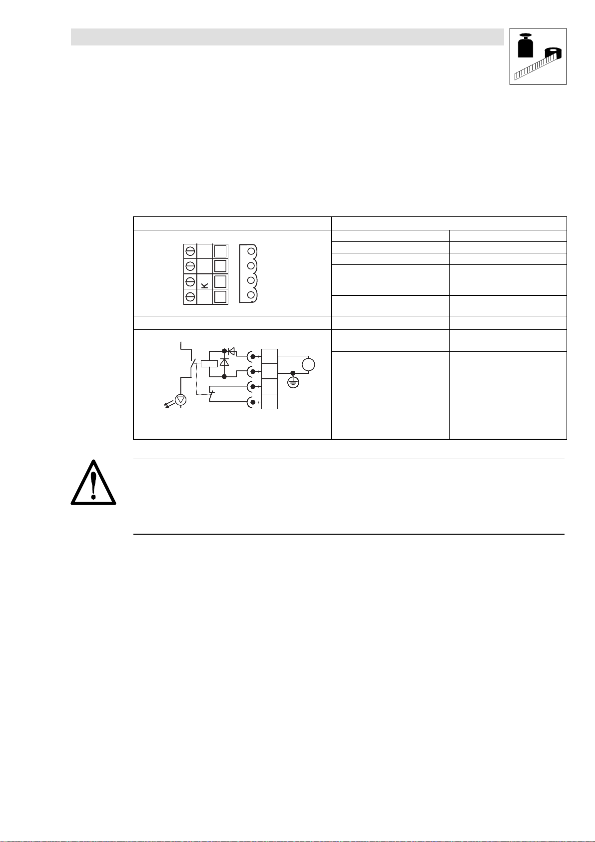
2.1 Safety relay - Technical data/wiring
Thesafetyrelayisconnectedtothefrontofthecontrollerby meansofthe4-pole plugX11.Thesafety
relay is equipped with a freewheeling diode and a reverse voltage protection diode.
Terminal assignment for plug X11 Data for the safety relay
Coil voltage at +20 °C +24 V DC (+19.5 ... 36.0 V)
3 43 3K 3 2
3 43 3K 3 2
3 43 3K 3 2
3 43 3K 3 2
3 43 3K 3 2
K 3 1
K 3 1
K 3 1
K 3 1
K 3 1
Wiring of plug X11 Electrical life time at rated load ~105operating cycles
+ 5 V
+ 5 V
+ 5 V
+ 5 V
K
K
K
K
S R
S R
S R
S R
+
+
+
+
I G B T
I G B T
I G B T
I G B T
• Max. permissible cable cross-section = 1.5 mm@
• Screw tightening torque = 0.5...0.6 Nm (4.4...5.3 Ibin)
3 4
3 4
3 4
3 4
3 4
3 3
3 3
3 3
3 3
3 3
K 3 2
K 3 2
K 3 2
K 3 2
K 3 2
K 3 1
K 3 1
K 3 1
K 3 1
K 3 1
X 1 1
X 1 1
X 1 1
X 1 1
3 4
3 4
3 4
3 4
3 3
3 3
3 3
3 3
K 3 2
K 3 2
K 3 2
K 3 2
K 3 1
K 3 1
K 3 1
K 3 1
D C + 2 4 V
D C + 2 4 V
D C + 2 4 V
D C + 2 4 V
Coil resistance at +20 °C 823 Ω±10%
Switching voltage max. 250 V AC or 200 V DC
Continuous current at max.
permissible ambient temperature
(ohmic load)
Control voltage - contact → coil
Control voltage - contact
Mechanical life time ~107operating cycles
=
=
=
=
Technical data
max. 1.5 A (250 V AC)
max.1.5A(60VDC)
max. 0.5 A (200 V DC)
AC 1500 V
→ contact
AC 1500 V
rms
rms
for 1 min
for 1 min
Warning!
The electrical reference point for the the safety relay coil must be connected to the PE conductor
system (DIN EN60204-1 paragraph 9.4.3)!
This is the only way to protect the unit from earth faults.
L EDB9300EN-V004 EN 4.0
5

Installation
Buy: www.ValinOnline.com | Phone 844-385-3099 | Email: CustomerService@valin.com
Show/Hide Bookmarks
3 Installation
3.1 Circuit for “Safe standstill with safety relay”
Theexample shows minimum wiring of the components. This ensures the troublefree operation of
the“Safe standstill” function of 93XX-V004 controllers.
S a f e t y d o o r m o n i t o r i n gE m e r g e n c y o f f S t a r t - S t o p m o m e n t a r y c o n t a c t p u s h b u t t o n
S 4
S 3
E m e r g e n c y o f f
S 1
A U S E I N
S 2
E m e r g e n c y o f f
s w i t c h i n g d e v i c e
A 1
L 1
L 2
L 3
F 1 . . F 3
K 4
9 3 x x
V 0 0 4
A 3
K 4
t
A 1
A 2
C W
K 2 a
r o t a t i o n
X 1 1
K 3 2 3 4 3 3 E 1K 3 1 E 2 2 8 3 9 5 9 X 5
K
S R
I G B T
Fig. 1 Minimum wiring for 93XX-V004 controllers with safety relay
to EN 954-1 control category 3 and EN 1037, stop category 1 to EN 60204-1
3.1.1 Description
For a circuit with a safety relay for emergency off and door lock follow EN954-1 control category
3 and EN 1037. The circuit in Fig. 1 shows a stop function of stop category 1 to EN 60204-1:
• The circuits for emergency off and door locking are two-channel circuits protected against
short circuits between signal cables. The integrated switching devices are equipped with
positively driven contacts.
S a f e t y d o o r
s w i t c h i n g d e v i c e
C C W
r o t a t i o n
Q S P
C W
C C W
r o t a t i o n
r o t a t i o n
K 4
K 3
t
A 2
K 2 a
K 4
+ 2 4 V
0 V
D C
G N D
R F R
+ 2 4 V
K 3
K 2 a
K 3K 2 bK 2 b
• The 24 V DC supplyforthestart/stop button(S1“OFF”,S2“ON”)flows through the contacts
of A1 (emergency off)and A2(safety door).
• A1 and A2and the relay K3 have an additive effect on the input “Quick-Stop” (QSP)of the
controller (A3)via terminal E1(CW rotation)and terminal E2 (CCWrotation).
• The appropriate control devices must be integrated to ensure a reversal of the direction of
rotation.
• If the safety door is opened during operation, there will be an off-delay on the mains
contactor and also the power supply to the controller. This will not occur if the feedback
contact K31 - K32 of the safety relay (K
X11 (2nd switch-off circuit).
6
EDB9300EN-V004 EN 4.0
)indicates activation of the external pulse inhibit via
SR
L
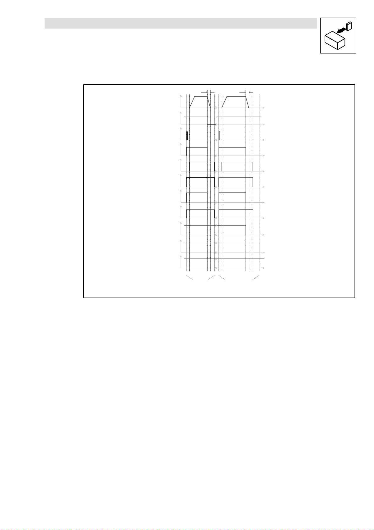
3.1.2 Time chart
Buy: www.ValinOnline.com | Phone 844-385-3099 | Email: CustomerService@valin.com
Show/Hide Bookmarks
Installation
n
S 1
S 2
Q S P
R F R
K
S R
K 2 a
K 2 b
S 4
t
A 2
K 4
t 1 t 2 t 3 t 4 t 5
t
Q S P
" S a f e s t a n d s t i l l "
f u n c t i o n v i a
s t a r t - s t o p m o m e n t a r y
c o n t a c t p u s h b u t t o n
t
Q S P
t 1 t 2 t 3 t 4 t 5 t6
" S a f e s t a n d s t i l l "
f u n c t i o n v i a
" O p e n i n g o f s a f e t y d o o r "
tt
tt
tt
tt
tt
tt
tt
tt
t
t
t
t
Fig. 2 Time characteristic for switching on and off “safe standstill with safety relay”
3.1.3 Time settings
• t1 to t2≥ 50 msec
Set the time relay K2b so that the controller is enabled at least 50 ms after K
switched.
• t3 to t4
t
= Time for controller-internal QSPramp
QSP
The time interval set must ensure that the controller can always be braked to a controlled
standstill when running at max. speed (t3 to t4).
• t3 to t5= t
Set the time relay K2a so that t
This ensures a controlled standstill according to stop category 1 of EN 60204-1. T he
controller will only be enabled again ( t5)once the motor has been braked to a controlled
standstill (t4).
• t3 to t6= Internal time of A1, A2 (t
tA1and tA2must be selected to ensure that the controller brakes the motor to standstill along
theQSPramp withinT
(K4)(t6). This will be required if
– theemergency off button (S3)is pressed during operation.
– the safety door is opened and the feedback contact of K
because of an error in the drive (t6)(2nd switch-off circuit).
+ min. 100 ms (guide value)
QSP
QSP
before the power supply is disconnected via the mains contactor
QSP
+ min. 100 ms safety time will always be achieved.
A1,tA2)
has been
SR
in the controller is not closed
SR
L EDB9300EN-V004 EN 4.0
7
 Loading...