

Page 1
(13360068)
SC & TC SERIES DYNAMIC BRAKING OPTION (For Use with External Resistors)
INSTALLATION AND OPERATION INSTRUCTIONS
(These instructions apply to Dynamic Braking modules 845-200, 845-400, and 845-500 ONLY)
The SC & TC Series Dynamic Braking option can be used with all SCD, SCL, SCM, and TCF models, and SCF models
with parameter version 306 or higher. The parameter version is displayed momentarily when power is applied, and also
appears on a label on the heatsink (For example: PV312).
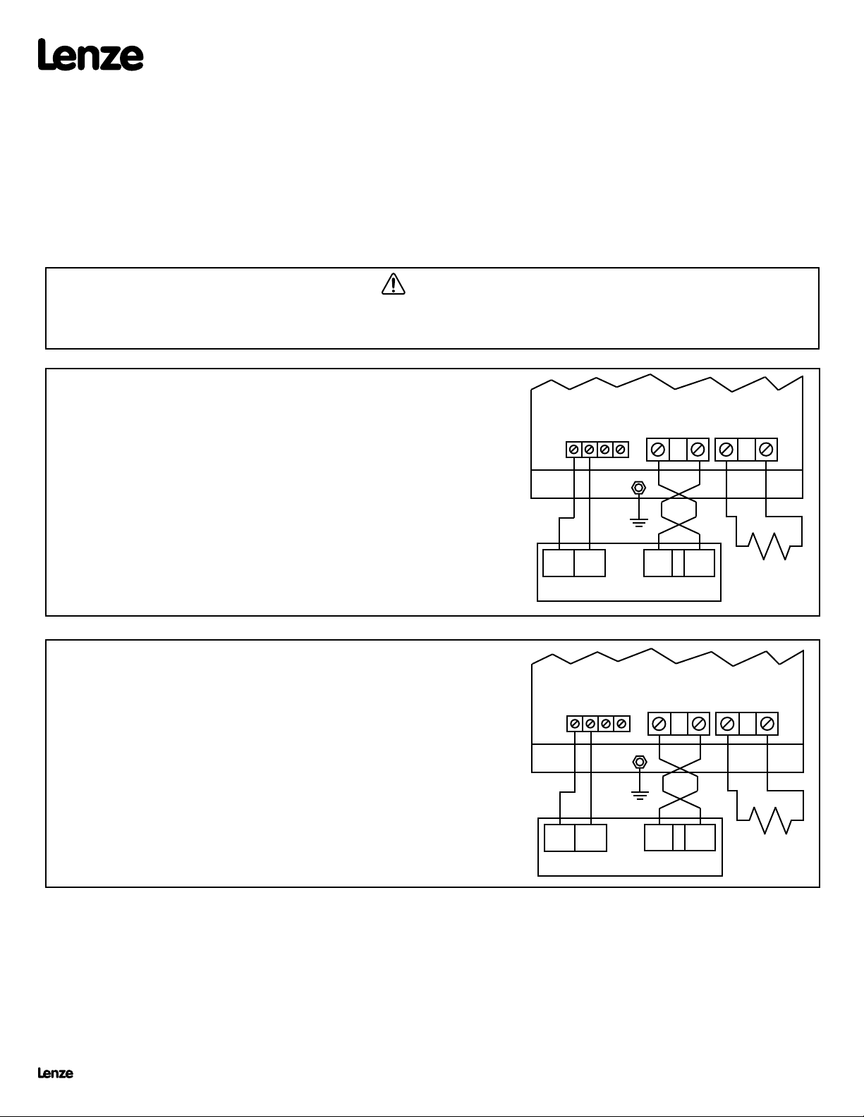
Remove power from the drive and wait three minutes before wiring the DB module. Incorrect wiring of the B+ and B- terminals will result in equipment
damage! The B+ terminal on the DB module must be connected to the B+ terminal on the drive, and the B- terminal on the DB module must be connected
to the B- terminal on the drive.
SCD & SCF SERIES DRIVES
WARNING!
PROGRAMMING:
1. Set Parameter 09 (TB-31 OUTPUT) to DYNAMIC BRAKING (04).
WIRING:
The diagram to the right illustrates how the DB module is wired to the SCD &
SCF Series drive.
See important wiring NOTES below.
DB OPTION MODULE
464743
B -
GND
B - B +
42
312
SCD / SCF DRIVE
B +
R + R -
EXTERNAL
RESISTORS
(SEE NOTE 3)
SCL & SCM SERIES DRIVES
PROGRAMMING
1. Set Parameter 12 (TB-13E FUNCTION) to DYNAMIC BRAKING (20).
WIRING
The diagram to the right illustrates how the DB module is wired to the SCL
and SCM Series drive.
See important wiring NOTES below.
DB OPTION MODULE
42
B -
464743
GND
B +
R + R -
2
13E
SCL / SCM DRIVE
B - B +
EXTERNAL
RESISTORS
(SEE NOTE 3)
NOTE 1: Use 18 AWG wire for control connections. Tighten DB module and drive control terminals to a torque of 2 lb-in
(0.2 Nm). Overtorque of terminals can result in damage.
NOTE 2: Use minimum 14 AWG wire for connections to B+, B-, R+, and R-. Tighten the DB module terminals to a torque
of 2 lb-in (0.2 Nm), and tighten the drive terminals to 4.5 lb-in (0.5 Nm). The B+ and B- wires MUST be twisted
together and must be less than 12 inches long. Twisting the R+ and R- wires is also recommended.
NOTE 3: External resistors (see selection chart on next page) are required when using Dynamic Braking modules 845-
200, 845-400, and 845-500. Only AC Tech supplied resistors are approved for use with 845 dynamic braking
modules.
Lenze Americas • 630 Douglas Street • Uxbridge MA 01569 • USA
Sales (800) 217-9100 • Service (508) 278 9100 • www.lenzeamericas.com
DG01C
13360068
Page 2
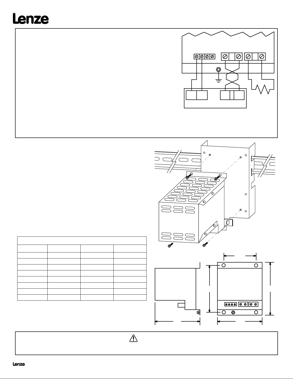
TCF SERIES DRIVES
PROGRAMMING
42
DB OPTION MODULE
B -
464743
B +
R + R -
1. Set Parameter 06 (TB-14 OUTPUT) to DB BRAKE (11).
WIRING
The diagram to the right illustrates how the DB module is wired to the TCF
drive.
Refer to important wiring NOTES herein.
NOTE 1: Use 18 AWG wire for control connections. Tighten DB module and drive
control terminals to a torque of 2 lb-in (0.2 Nm). Overtorque of terminals
can result in damage.
NOTE 2: Use minimum 14 AWG wire for connections to B+, B-, R+, and R-. Tighten the DB module terminals to a torque of 2 lb-in (0.2 Nm), and
tighten the drive terminals to 4.5 lb-in (0.5 Nm). The B+ and B- wires MUST be twisted together and must be less than 12 inches long.
Twisting the R+ and R- wires is also recommended.
NOTE 3: External resistors (see selection chart below) are required when using Dynamic Braking modules 845-200, 845-400, and 845-500. Only AC
Tech supplied resistors are approved for use with 845 dynamic braking modules.
14
11
GND
TCF DRIVE
B - B +
EXTERNAL
RESISTORS
(SEE NOTE 3)
MOUNTING THE DYNAMIC BRAKING MODULE
The diagram to the right illustrates how to mount the DB Module. The DB
Module is compatible with the DIN Rail Mounting Kit option, or can simply be
mounted to a flat surface such as an electrical panel.
NOTE: DO NOT mount the resistors below the drive! The resistors generate
heat, and must be mounted above or to the side of the drive.
DIN RAIL
BRACKET
SELECTING EXTERNAL RESISTORS
Use the chart below to select the proper external resistor assembly:
DB MODULE
EXTERNAL RESISTER ASSEMBLIES
HP 240/200 Vac 480/400 Vac 590/480 Vac
0.25 - 0.5 841-001 841-002 N/A
1 - 1.5 841-002 841-002 841-001
2 841-003 841-003 841-002
3 841-005 841-005 841-004
5 841-006 841-006 841-005
7.5 - 10 841-007 841-007 841-008
15 - 20 841-009 841-009 841-010
25 - 30 N/A 841-011 841-012
NOTE: These resistor assemblies are the same as those used with the MC
Series drives. The DB Module does not include short-circuit protection for the
external resistors. If short-circuit protection is desired, fusing must be supplied
by the customer. Consult Lenze AC Tech.
SIDE VIEW
4.06"
3.1"
WARNING!
Hazard of electric shock! External resistors are connected to the drive's DC bus, which can reach 950 VDC. Connections to external resistors must be
electrically insulated and mechanically shielded for safety. High Voltage warning signs are also recommended.
2.00"
FRONT
VIEW
GND
3.1"
4.6"
Lenze Americas • 630 Douglas Street • Uxbridge MA 01569 • USA
Sales (800) 217-9100 • Service (508) 278 9100 • www.lenzeamericas.com
DG01C
13360068
 Loading...