

Page 1
SMVector Additional I/O Module
Installation and Operation Manual
Page 2

About These Instructions
This documentation applies to the optional Additional I/O module for the SMVector inverter and should be used
in conjunction with the SMVector Operating Instructions (Document SV01) that shipped with the drive. These
documents should be read in their entirety as they contain important technical data and describe the installation
and operation of the drive.
NOTE
To use the I/O Module with SMVector drives rated at 0.33 to 10 HP (0.25 to 7.5 kW) requires
that the drive has software version 3.0 or higher. The software version can be found in
the SMVector drive diagnostic parameter P501. To use the I/O Module options the value
displayed in P501 must be 3.00 or higher.
SMVector drives rated at 15 HP (11.0 kW) and higher all support the I/O options models so
there is no need to verify the value in P501.
© 2008 Lenze AC Tech Corporation
No part of this documentation may be copied or made available to third parties without the explicit written approval
of Lenze AC Tech Corporation. All information given in this documentation has been carefully selected and tested
for compliance with the hardware and software described. Nevertheless, discrepancies cannot be ruled out. Lenze
AC Tech does not accept any responsibility nor liability for damages that may occur. Any necessary corrections will
be implemented in subsequent editions.
Page 3

Contents
1 Safety Information .............................................................................................................1
1.1 Warnings, Cautions and Notes ..............................................................................1
1.1.1 General ....................................................................................................1
1.1.2 Application ...............................................................................................1
1.1.3 Installation ...............................................................................................1
1.1.4 Electrical Connection ................................................................................2
1.1.5 Operation .................................................................................................2
2 Introduction .......................................................................................................................3
2.1 Module Overview ..................................................................................................3
2.2 Module Specification ............................................................................................3
2.3 Module Identification Label ...................................................................................3
3 Installation ........................................................................................................................4
3.1 Mechanical Installation .........................................................................................4
3.2 Module Terminal Block .........................................................................................5
3.3 Electrical Installation .............................................................................................6
3.3.1 Terminal Description ................................................................................6
3.3.2 Module Wiring ..........................................................................................6
4 Commissioning .................................................................................................................7
4.1 Network Parameters (P400) ..................................................................................7
4.2 Additional I/O Module Parameters .........................................................................8
4.3 Display .................................................................................................................10
i ALSV01B
Page 4

1 Safety Information
1.1 Warnings, Cautions and Notes
1.1.1 General
Some parts of Lenze controllers (frequency inverters, servo inverters, DC controllers) can be live, moving
and rotating. Some surfaces can be hot.
Non-authorized removal of the required cover, inappropriate use, and incorrect installation or operation
creates the risk of severe injury to personnel or damage to equipment.
All operations concerning transport, installation, and commissioning as well as maintenance must be
carried out by qualified, skilled personnel (IEC 364 and CENELEC HD 384 or DIN VDE 0100 and IEC report
664 or DIN VDE0110 and national regulations for the prevention of accidents must be observed).
According to this basic safety information, qualified skilled personnel are persons who are familiar with
the installation, assembly, commissioning, and operation of the product and who have the qualifications
necessary for their occupation.
1.1.2 Application
Safety Information
Drive controllers are components designed for installation in electrical systems or machinery. They are
not to be used as appliances. They are intended exclusively for professional and commercial purposes
according to EN 61000-3-2. The documentation includes information on compliance with EN 61000-3-2.
When installing the drive controllers in machines, commissioning (i.e. the starting of operation as directed)
is prohibited until it is proven that the machine complies with the regulations of the EC Directive 2006/42/
EC (Machinery Directive); EN 60204 must be observed.
Commissioning (i.e. starting drive as directed) is only allowed when there is compliance to the EMC
Directive (2004/108/EC).
The drive controllers meet the requirements of the Low Voltage Directive 2006/95/EC. The harmonised
standards of the series EN 50178/DIN VDE 0160 apply to the controllers.
The availability of controllers is restricted according to EN 61800-3. These products can cause
radio interference in residential areas. In the case of radio interference, special measures may be
necessary for drive controllers.
1.1.3 Installation
Ensure proper handling and avoid excessive mechanical stress. Do not bend any components and do not
change any insulation distances during transport or handling. Do not touch any electronic components
and contacts. Controllers contain electrostatically sensitive components, which can easily be damaged by
inappropriate handling. Do not damage or destroy any electrical components since this might endanger
your health! When installing the drive ensure optimal airflow by observing all clearance distances in the
drive's user manual. Do not expose the drive to excessive: vibration, temperature, humidity, sunlight, dust,
pollutants, corrosive chemicals or other hazardous environments.
1 ALSV01B
Page 5
Safety Information
1.1.4 Electrical Connection
When working on live drive controllers, applicable national regulations for the prevention of accidents (e.g.
VBG 4) must be observed.
The electrical installation must be carried out in accordance with the appropriate regulations (e.g.
cable cross-sections, fuses, PE connection). Additional information can be obtained from the regulatory
documentation.
The regulatory documentation contains information about installation in compliance with EMC (shielding,
grounding, filters and cables). These notes must also be observed for CE-marked controllers.
The manufacturer of the system or machine is responsible for compliance with the required limit values
demanded by EMC legislation.
1.1.5 Operation
Systems including controllers must be equipped with additional monitoring and protection devices according
to the corresponding standards (e.g. technical equipment, regulations for prevention of accidents, etc.).
You are allowed to adapt the controller to your application as described in the documentation.
DANGER!
• After the controller has been disconnected from the supply voltage, do not touch the live
components and power connection until the capacitors have discharged. Please observe
the corresponding notes on the controller.
• Do not continuously cycle input power to the controller more than once every three minutes.
• Close all protective covers and doors during operation.
WARNING!
Network control permits automatic starting and stopping of the inverter drive. The system design
must incorporate adequate protection to prevent personnel from accessing moving equipment
while power is applied to the drive system.
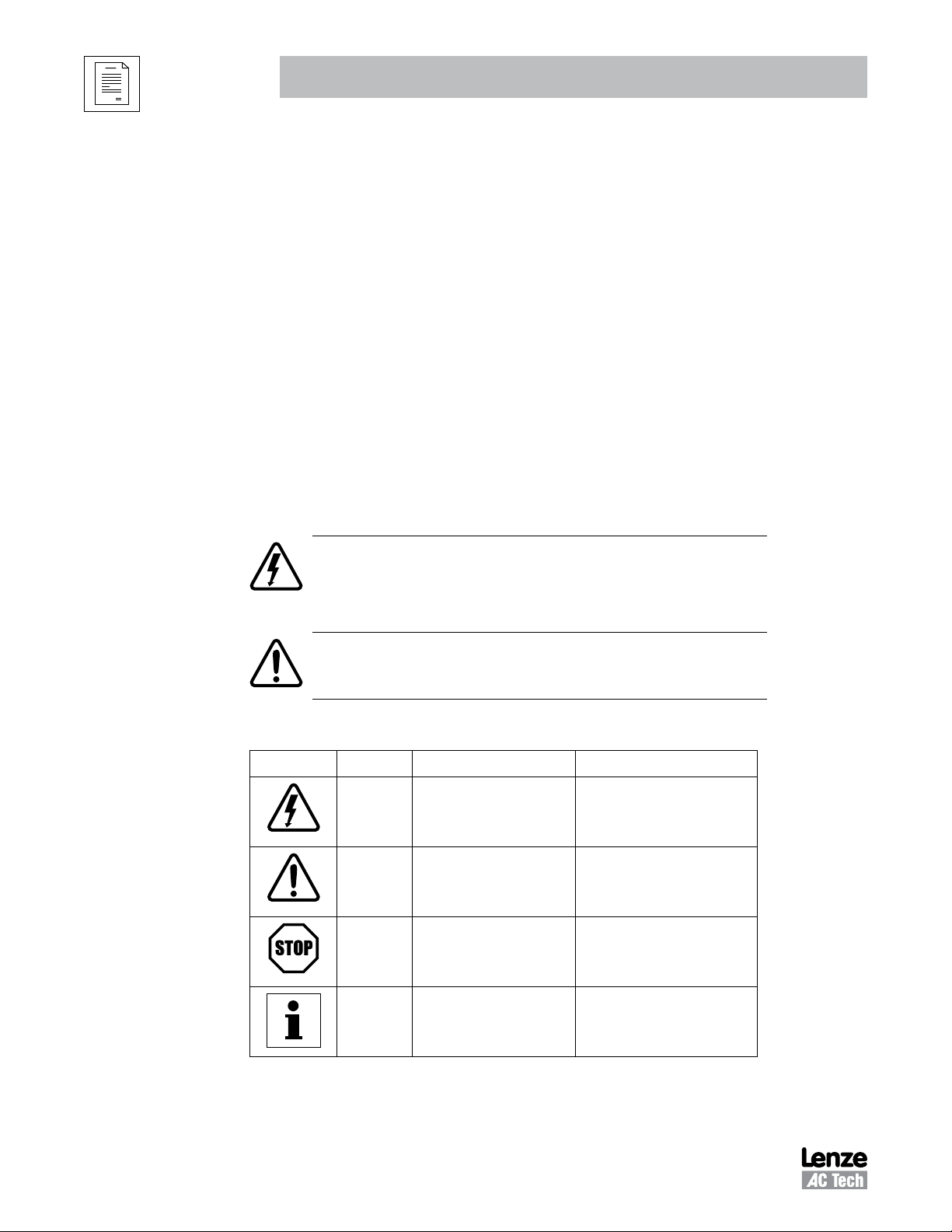
Table 1: Pictographs used in these instructions
Pictograph Signal word Meaning Consequences if ignored
DANGER!
WARNING!
STOP!
NOTE
Warning of Hazardous Electrical
Impending or possible danger
Possible damage to equipment Damage to drive system or its
Useful tip: If observed, it will
make using the drive easier
ALSV01B 2
Voltage.
for persons
Reference to an imminent danger
that may result in death or serious
personal injury if the corresponding
measures are not taken.
Death or injury
surroundings
Page 6

2 Introduction
This manual provides installation and operational data specific to the Additional I/O Module for the SMVector
series inverters. This manual is a supplement (not a substitution for) the standard SMVector - Frequency
Inverter Operating Instructions (document number SV01).
This document assumes that the reader has a working knowledge of the standard SMVector Frequency
Inverter and has familiarity with the programming and operation of the SMVector Frequency Inverter. Please
consult the SMVector - Frequency Inverter Operating Instructions (SV01) for more details.
2.1 Module Overview
The Additional I/O Module is available in two configurations (ESVZAL0, ESVZAL1) for use with the SMVector
Frequency Inverter. The modules are intended to supplement the standard I/O functions available in the
SMVector inverter.
The I/O module fits into the SMVector inverter terminal cover. This allows for easy field installation and
does not add to the overall size of the SMVector inverter.
SMVector inverters that are fitted with an additional I/O module option will no longer have the capability of
accommodating an optional communication module.
Introduction
2.2 Module Specification
• P/N ESVZAL0: 1 programmable form C relay output.
• P/N ESVZAL1: 1 programmable form C relay output and 2 programmable digital inputs.
2.3 Module Identification Label
Figure 1 illustrates the labels on the SMV Additional I/O Module. The SMVector Additional I/O Module is
identifiable by:
• Label affixed to side of the module.
• Part Number ESVZALx on module label.
Right-hand Label:
Ratings & Certifications
Additional I/O ONLY
S/N: 123456789
Left-hand Label:
Module Data
SMV I/O
TYPE: ESVZAL1
ID-NO: 12345678
ESVZAL1-000XX1A10
LISTED
A
B
C
D
E
A: Module Type
B: Model Number
C: Lenze Order Number
D: Firmware Revision
E: Hardware Revision
Figure 1: Additional I/O Module Label
3 ALSV01B
Page 7

Installation
3 Installation
3.1 Mechanical Installation
1. Ensure that for safety reasons the AC supply has been disconnected before opening the terminal
cover.
2. Insert the Additional I/O module in the terminal cover and securely “click” into position as illustrated
in Figure 2.
3. Wire the cables to the connector provided and plug the connector into the option module.
4. Align terminal cover for re-fitting, connect the module umbilical cord to the drive then close the cover
and secure, as shown in Figure 3.
0.5 Nm/ 4.5 lb-in
<_ 2.8 mm²
(12-22 AWG)
7mm
Red wire and black wire
are present in the ESVZAL1
module. They are not
present in the ESVZAL0
module. Refer to wiring
instructions below.
0.5 Nm/ 4.5 lb-in
<_ 2.8 mm²
13F
13G
21 20
19
(12-22 AWG)
7mm
13F
13G
21 20
19
Figure 2a: NEMA 1 (IP31) Installation Figure 2b: NEMA 4X (IP65) Installation
The ESVZAL1 I/O Option Module
contains 1 red wire and 1 black wire
that must be wired into the standard
SMVector Inverter terminal strip.
Connect the black wire to terminal #2.
Connect the red wire to terminal #11.
Refer to adjacent diagram.
Figure 2c: Wiring the ESVZAL1 I/O Module
ALSV01B 4
Terminal Strip of Standard SMVector Inverter
1 2 5 6254
Black and Red wires from ESVZAL1 Module
11 13A 13B 13C
14
30 16 17
Page 8

Installation
Figure 3: Re-Installing the Terminal Cover
3.2 Module Terminal Block
Table 2 identifies the terminals and describes the function of each. Figure 4 illustrates the Additional I/O 5
pole 5mm pluggable connector.
Terminal Function Description
19 Relay N.O.
20 Relay Common
21 Relay N.C.
13F Digital Input Available only on ESVZAL1
13G Digital Input Available only on ESVZAL1
Table 2: Additional I/O Terminals
19
20
21
13F
13G
Figure 4: Additional I/O Connector
5 ALSV01B
Page 9

Installation
Terminal Strip TB#4
3.3 Electrical Installation
3.3.1 Terminal Description
Table 3 contains each terminal's electrical specification and any parameter description associated with
that terminal.
Terminal Function Description
19 Relay N.O. Relay output configurable with P441, P144
20 Relay Common
21 Relay N.C.
Table 3: Additional I/O Module Specifications
AC 250 V / 3 A 17 DC 24 V / 2 A … 240 V / 0.22 A, non-inductive
NOTE
For ESVZAL0:
Control and communications terminals provide reinforced insulation when the drive is connected to a power system
rated up to 300V between phase to ground (PE) and the applied voltage on terminals 19, 20 and 21 is less than 250
VAC between phase and ground (PE)
For ESVZAL1:
Control and communications terminals provide reinforced insulation when the drive is connected to a power system
rated up to 300V between phase to ground (PE) and the applied voltage on terminals 19, 20 and 21 is less than 150
VAC between phase and ground (PE)
Control and communications terminals provide basic insulation when the drive is connected to a power system
rated up to 300V between phase to ground (PE) and the applied voltage on terminals 19, 20 and 21 is less than 250
VAC between phase and ground (PE).
3.3.2 Module Wiring
Figure 5 illustrates the wiring of the ESVZAL0 and ESVZAL1 modules.
13F Digital Input 13F configurable with P426
13G Digital Input
The assertion level of Terminals 13F and 13G will match the assertion level of
the standard SMVector digital inputs 13A, 13B, 13C, etc…
Refer to the description of P120 and Terminal #4 in the SMVector - Frequency
13G configurable with P427
Input Impedance = 4.3 kohm
Inverter Operating Instructions (SV01)
ALSV01B 6
19 20
21
19 20
To SMVector Control
21
13F
Figure 5a: ESVZAL0 Figure 5b: ESVZAL1
NOTE
To assert terminals 13F and 13G with external power
sources, refer to section 3.2.3 of the SMVector
Operating Instructions (SV01)
13G
Page 10

4 Commissioning
4.1 Network Parameters (P400)
Commissioning
Code Possible Settings
No. Name Default Selection
Network Protocol 0 Not Active This parameter setting is based upon the
p400
1 Remote Keypad
2 Modbus RTU
3 CANopen
4 DeviceNet
5 Ethernet
6 Profibus
7 Lecom-B
8 I/O Module
Module Type Installed 0 0 No Module Installed Module type format: 0xAABC; Drive Display:
p401
1 Basic I/O (0x0100, 1.0.0)
2 RS485/Rem. Keypad (0x0200, 2.0.0)
3 CANopen (0x0300, 3.0.0)
11 PROFIBUS (0x1100, 11.0.0)
12 Ethernet (0x1200, 12.0.0)
Module Status 0 0 Not Initialized
P402
1 Initialization: Module to EPM
2 Initialization: EPM to Module
3 Online
4 Failed Initialization Error
5 Time-out Error
6 Initialization Failed Module type mismatch P401
7 Initialization Error Protocol selection mismatch P400
Module Reset 0 0 No Action Returns module parameters 401…499 to the
P403
1 Reset parameters to default values
Module Timeout Action 0 0 No Fault Action to be taken in the event of a Module/
P404
1 STOP (see P111)
2 Quick Stop
3 Fault (F_ntF)
Current Network Fault 0 No Fault
P405
1 F.nF1 NetIdle Mode
2 F.nF2 Loss of Ethernet I/O connection
3 F.nF3 Network Fault
4 F.nF4 Explicit Message Timeout
5 F.nF5 Overall Network Timeout
6 F.nF6 Overall Explicit Timeout
7 F.nF7 Overall I/O Message Timeout
Proprietary Manufacturer specific
P406
p407 … P499
Module Specific Parameters
network or I/O module that is installed.
AA.B.C
AA = Module Type
B = Major revision
C = minor revision
default values shown in the manual
Drive Time-out.
Time is fixed at 200ms
STOP is by the method selected in P111.
Refer to the Communications Reference Guide
specific to the network or I/O module installed.
IMPORTANT
NOTE
Set P400 = 8 for the SMVector drive to communicate with the additional I/O module.
7 ALSV01B
Page 11

Commissioning
4.2 Additional I/O Module Parameters
In addition to the parameters detailed in the SMVector Frequency Inverter Operating Instructions (SV01),
installing the Additional I/O Module provides access to supplementary parameters exclusive to the Additional
I/O Module. Table 4 lists these supplementary parameters.
Table 4: Additional I/O Module Parameters
Code Possible Settings
No. Name Default Selection
TB-13F Input
P426
Function
TB-13G Input
p427
Function
WARNING!
Jog overrides all STOP commands! To stop the drive while in Jog mode, the Jog input must be deactivated or a fault condition induced.
NOTE
• When input is activated, settings 1...7 override P101
• When TB-13A to TB-13D; TB-13F and TB-13G are configured for Auto References other than MOP, TB-13G overrides TB-13F, TB-13F
overrides TB-13D, TB-13D overrides TB-13C, TB-13C overrides TB-13B and TB-13B overrides TB-13A. Any other Auto Reference will
have priority over MOP.
• Settings 10...14 are only valid in Terminal Strip mode (P100 = 1, 4, 5, 6)
• If Start/Run/Jog Forward and Start/Run/Jog Reverse are both activated, drive will STOP
• If Jog input is activated while the drive is running, the drive will enter Jog mode; when Jog input is deactivated, drive will STOP
• An F.AL fault will occur if the Assertion Level switch (ALsw) position does not match the P120 setting and any of the digital inputs
(P121...P124, P426 ... P427) are set to a value other than 0.
• An F.IL fault will occur under the following conditions:
- TB-13A...TB-13D and TB-13F...TB-13G settings are duplicated (each setting, except 0 and 3, can only be used once)
- One input is set to “MOP Up” and another is not set to “MOP Down”, or vice-versa.
- One input is set to 10 and another input is set to 11…14.
- One input is set to 11 or 12 and another input is set for 13 or 14.
• TB-13D and P124 exist in 15HP (11kW) and greater drives only
0 None Disables input
0
1 AUTO Reference: 0-10 VDC For frequency mode, see P160...P161,
2 AUTO Reference: 4-20 mA
RESERVED
4 AUTO Reference: MOP Up • Normally open: Close input to increase or decrease
5 AUTO Reference: MOP Down
6 AUTO Reference: Keypad
7 AUTO Reference: Network
8 Control Select Use when P100 = 4, 5 to switch between terminal strip
9 Network Enable Required to start the drive through the network.
10 Reverse Rotation Open = Forward Closed = Reverse
11 Start Forward
12 Start Reverse
13 Run Forward
14 Run Reverse
15 Jog Forward Jog Forward speed = P134
16 Jog Reverse Jog Reverse speed = P135
17 Accel/Decel #2 Refer to P125, P126
18 DC Brake Refer to P174; close input to override P175
19 Auxiliary Ramp to Stop Normally closed: Opening input will ramp drive to STOP
20 Clear Fault Close to reset fault
21 External Fault
22 Inverse External Fault
F.EF
F.EF
For PID mode, see P204…P205,
For vector torque mode, see P330
speed, PID setpoint or torque setpoint.
• MOP Up is not active while in STOP
control and local or remote keypad control.
Refer to Note for typical circuit
Refer to Note for typical circuit
Active even if P112 = 0
according to P127, even if P111 is set to Coast (0 or 1).
Normally closed circuit; open to trip
Normally open circuit; close to trip
IMPORTANT
ALSV01B 8
Page 12

Commissioning
Code Possible Settings
No. Name Default Selection
p441
Relay Output
TB-19, 20, 21
0 0 None Disables the output
1 Run Energizes when the drive is running
2 Reverse Energizes when reverse rotation is active
3 Fault De-energizes when the drive trips, or power is removed
4 Inverse Fault Energizes when the drive trips
5 Fault Lockout P110 = 3...6: De-energizes if all restart attempts fail
6 At Speed Energizes when output frequency = commanded frequency
7 Above Preset Speed #6 Energizes when output frequency > P136
8 Current Limit Energizes when motor current = P171
9 Follower Loss (4-20 mA) Energizes when 4-20 mA signal falls below 2 mA
10 Loss of Load Energizes when motor load drops below P145; Refer to
11 Local Keypad Control Active
12 Terminal Strip Control Active
13 Remote Keypad Control Active
14 Network Control Active
15 Standard Reference Active Energizes when P101 reference is active
16 Auto Reference Active Energizes when Auto Reference is activated using TB-13
17 Sleep Mode Active Refer to P240...P242
18 PID Feedback < Min. Alarm Energizes when PID feedback signal < P214
19 Inverse PID Feedback < Min. Alarm De-energizes when PID feedback signal < P214
20 PID Feedback > Max Alarm Energizes when PID feedback signal > P215
21 Inverse PID Feedback > Max Alarm De-energizes when PID feedback signal > P215
22 PID Feedback within
Min/Max Alarm range
23 PID Feedback outside
Min/Max Alarm range
24 Reserved
25 Network Activated Requires 15HP (11kW) or higher drive.
26 Loss of 0-10V Input Energizes when 0-10V signal < P158
27 Sequencer Controlled State set in individual sequencer segments
28 Sequencer Active
29 Sequencer Suspended
30 Sequence Done End sequence
31 Output Frequency = 0.0Hz Output inactive
Digital Output
P144
Inversion
P144
0 NO NO NO
1 NO NO YES
2 NO YES NO
3 NO YES YES
4 YES NO NO
5 YES NO YES
6 YES YES NO
7 YES YES YES
NOTE
Inverting P140, P142 or P441 when the parameter is set to NONE (0) will result in the output being
energized continuously.
Invert
P441
Invert
P142
Invert
P140
IMPORTANT
P146 also
Energizes when the selected source is active for start
control
input; refer to P121...P124
Energizes when PID feedback signal is within the Min/Max
Alarm range; refer to P214, P215
Energizes when PID feedback signal is outside the Min/Max
Alarm range; refer to P214, P215
No function for 0.33-10HP (0.25kW-7.5kW) drives.
Used to invert the selections for P140, P441 (Relay Output)
and P142 (TB-14 Output).
EXAMPLE: When P140 = 6 (AT SPEED), the relay is
energized when output frequency = commanded
frequency. IF P144=1, 3, 5 or 7, then P140 is inverted
(INVERSE AT SPEED) and the relay is energized when the
output frequency does not equal the command frequency.
9 ALSV01B
Page 13

4.3 Display
Parameter P530 allows monitoring of the control terminal points and common drive conditions.
An illuminated LED segment indicates:
• the protective circuit is active (LED 1)
• the Logic Assertion Switch is set to High (+)
• input terminal is asserted (LED 2)
• output terminal is energized (LED 4)
• the Charge Relay is not a terminal, this segment will be illuminated when the Charge Relay is energized
(LED 4).
Commissioning
Current Limit Diagnostic
Logic Assertion Switch
Input 1
Input 13B
Relay
Output 14
Input 13D*
LED #
1 2
3
4
Charge
Relay
Additional I/O Module only
Input 13C
Input 13A
Factory Reserved
Protective Diagnostic
* Input 13D available on 15-60HP (11-45kW) models only
Auxiliary Relay
Input 13F
Input 13E
Figure 6: Status Indicators
ALSV01B 10
Page 14

Lenze AC Tech Corporation
630 Douglas Street • Uxbridge MA 01569 • USA
Sales: 800-217-9100 •Service: 508-278-9100
www.lenzeamericas.com
SMVector Additional I/O Module
Installation & Operation Manual (ALSV01B-en2)
(13376253)
 Loading...