

Page 1
EDS84DPSO01
.Ez#
L−force Drives
Ä.Ez#ä
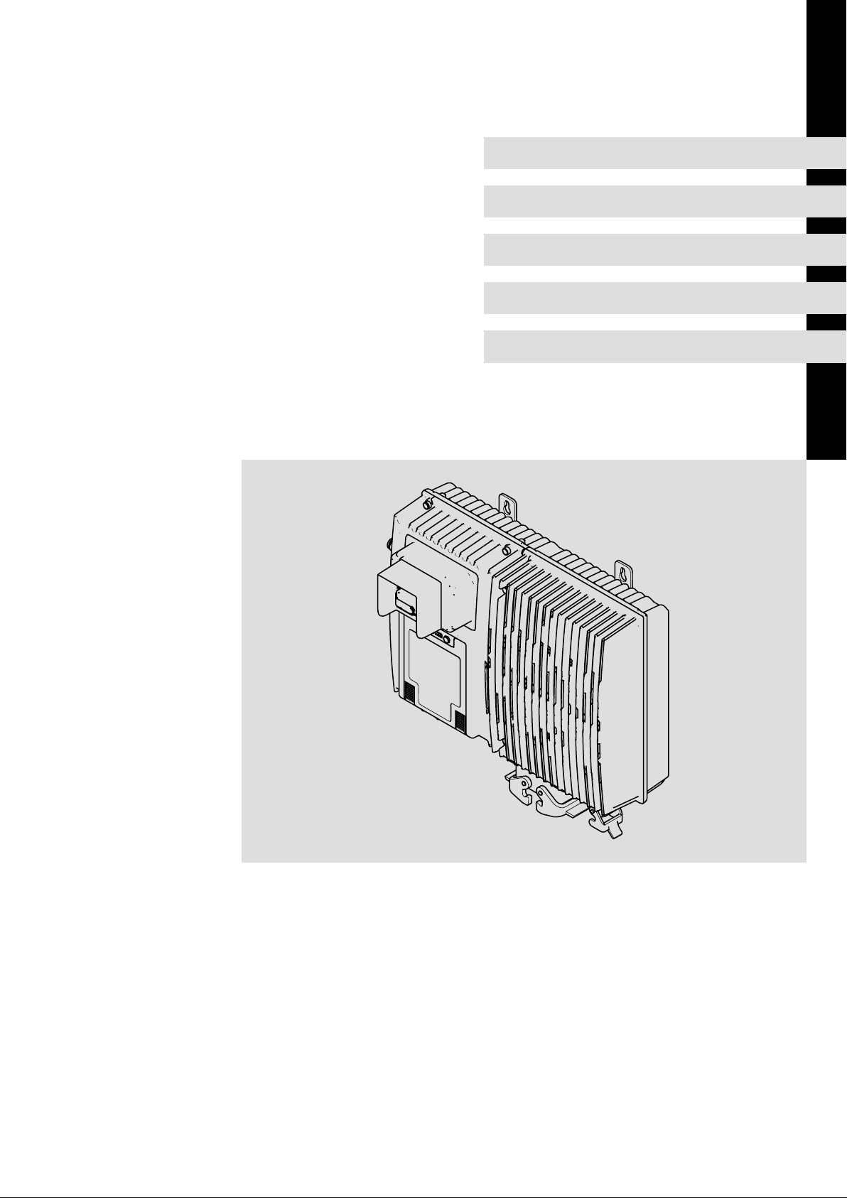
8400 protec
Translation
Manual
SO10 / SO20 / SO30
Drive−based safety
l
Page 2

, Please read these instructions and the documentation of the standard device before you
start working!
Observe the safety instructions given therein!
0Fig. 0Tab. 0
Page 3

Contents i
1 About this documentation 5 . . . . . . . . . . . . . . . . . . . . . . . . . . . . . . . . . . . . . . . . . . . . . . . . . .
1.1 Document history 5 . . . . . . . . . . . . . . . . . . . . . . . . . . . . . . . . . . . . . . . . . . . . . . . . . . . .
1.2 Conventions used 6 . . . . . . . . . . . . . . . . . . . . . . . . . . . . . . . . . . . . . . . . . . . . . . . . . . . .
1.3 Terms and abbreviations used 7 . . . . . . . . . . . . . . . . . . . . . . . . . . . . . . . . . . . . . . . . . .
1.4 Notes used 8 . . . . . . . . . . . . . . . . . . . . . . . . . . . . . . . . . . . . . . . . . . . . . . . . . . . . . . . . . .
2 Safety engineering 9 . . . . . . . . . . . . . . . . . . . . . . . . . . . . . . . . . . . . . . . . . . . . . . . . . . . . . . . .
2.1 Introduction 9 . . . . . . . . . . . . . . . . . . . . . . . . . . . . . . . . . . . . . . . . . . . . . . . . . . . . . . . . .
2.2 Important notes 10 . . . . . . . . . . . . . . . . . . . . . . . . . . . . . . . . . . . . . . . . . . . . . . . . . . . . . .
2.2.1 Hazard and risk analysis 11 . . . . . . . . . . . . . . . . . . . . . . . . . . . . . . . . . . . . . . .
2.2.2 Standards 11 . . . . . . . . . . . . . . . . . . . . . . . . . . . . . . . . . . . . . . . . . . . . . . . . . . .
2.3 Acceptance 12 . . . . . . . . . . . . . . . . . . . . . . . . . . . . . . . . . . . . . . . . . . . . . . . . . . . . . . . . . .
2.3.1 Description 12 . . . . . . . . . . . . . . . . . . . . . . . . . . . . . . . . . . . . . . . . . . . . . . . . . .
2.3.2 Periodic inspections 12 . . . . . . . . . . . . . . . . . . . . . . . . . . . . . . . . . . . . . . . . . . .
2.4 Basics for safety sensors 13 . . . . . . . . . . . . . . . . . . . . . . . . . . . . . . . . . . . . . . . . . . . . . . .
3 Safety option 10 14 . . . . . . . . . . . . . . . . . . . . . . . . . . . . . . . . . . . . . . . . . . . . . . . . . . . . . . . . . . .
3.1 Operating mode 14 . . . . . . . . . . . . . . . . . . . . . . . . . . . . . . . . . . . . . . . . . . . . . . . . . . . . . .
3.1.1 Introduction 14 . . . . . . . . . . . . . . . . . . . . . . . . . . . . . . . . . . . . . . . . . . . . . . . . .
3.1.2 Disconnecting paths 14 . . . . . . . . . . . . . . . . . . . . . . . . . . . . . . . . . . . . . . . . . .
3.1.3 Safety status 15 . . . . . . . . . . . . . . . . . . . . . . . . . . . . . . . . . . . . . . . . . . . . . . . . .
3.1.4 Fail−safe status 15 . . . . . . . . . . . . . . . . . . . . . . . . . . . . . . . . . . . . . . . . . . . . . . .
3.2 Status display 16 . . . . . . . . . . . . . . . . . . . . . . . . . . . . . . . . . . . . . . . . . . . . . . . . . . . . . . .
3.3 Technical data 17 . . . . . . . . . . . . . . . . . . . . . . . . . . . . . . . . . . . . . . . . . . . . . . . . . . . . . . .
3.4 Electrical installation 18 . . . . . . . . . . . . . . . . . . . . . . . . . . . . . . . . . . . . . . . . . . . . . . . . . .
3.5 Certification 19 . . . . . . . . . . . . . . . . . . . . . . . . . . . . . . . . . . . . . . . . . . . . . . . . . . . . . . . . .
4 Safety option 20 20 . . . . . . . . . . . . . . . . . . . . . . . . . . . . . . . . . . . . . . . . . . . . . . . . . . . . . . . . . . .
4.1 Operating mode 20 . . . . . . . . . . . . . . . . . . . . . . . . . . . . . . . . . . . . . . . . . . . . . . . . . . . . . .
4.1.1 Introduction 20 . . . . . . . . . . . . . . . . . . . . . . . . . . . . . . . . . . . . . . . . . . . . . . . . .
4.1.2 Disconnecting paths 21 . . . . . . . . . . . . . . . . . . . . . . . . . . . . . . . . . . . . . . . . . .
4.1.3 Safety status 21 . . . . . . . . . . . . . . . . . . . . . . . . . . . . . . . . . . . . . . . . . . . . . . . . .
4.1.4 Fail−safe status 21 . . . . . . . . . . . . . . . . . . . . . . . . . . . . . . . . . . . . . . . . . . . . . . .
4.2 Status display 22 . . . . . . . . . . . . . . . . . . . . . . . . . . . . . . . . . . . . . . . . . . . . . . . . . . . . . . .
4.3 Technical data 23 . . . . . . . . . . . . . . . . . . . . . . . . . . . . . . . . . . . . . . . . . . . . . . . . . . . . . . .
4.4 Electrical installation 24 . . . . . . . . . . . . . . . . . . . . . . . . . . . . . . . . . . . . . . . . . . . . . . . . . .
4.5 Certification 25 . . . . . . . . . . . . . . . . . . . . . . . . . . . . . . . . . . . . . . . . . . . . . . . . . . . . . . . . .
4.6 Safety functions 26 . . . . . . . . . . . . . . . . . . . . . . . . . . . . . . . . . . . . . . . . . . . . . . . . . . . . . .
4.7 Safe parameter setting 27 . . . . . . . . . . . . . . . . . . . . . . . . . . . . . . . . . . . . . . . . . . . . . . . .
4.7.1 Parameter setting 27 . . . . . . . . . . . . . . . . . . . . . . . . . . . . . . . . . . . . . . . . . . . . .
4.7.2 Parameter sets and axes 30 . . . . . . . . . . . . . . . . . . . . . . . . . . . . . . . . . . . . . . .
EDS84DPSO01 EN 2.1
l 3
Page 4

Contentsi
4.8 Error management 31 . . . . . . . . . . . . . . . . . . . . . . . . . . . . . . . . . . . . . . . . . . . . . . . . . . .
4.8.1 Error states 31 . . . . . . . . . . . . . . . . . . . . . . . . . . . . . . . . . . . . . . . . . . . . . . . . . .
4.8.2 Logbook 31 . . . . . . . . . . . . . . . . . . . . . . . . . . . . . . . . . . . . . . . . . . . . . . . . . . . . .
4.9 Response times 32 . . . . . . . . . . . . . . . . . . . . . . . . . . . . . . . . . . . . . . . . . . . . . . . . . . . . . .
4.9.1 Response times of the inputs 33 . . . . . . . . . . . . . . . . . . . . . . . . . . . . . . . . . . .
4.9.2 Response times of the safety bus 34 . . . . . . . . . . . . . . . . . . . . . . . . . . . . . . . .
5 Safety option 30 35 . . . . . . . . . . . . . . . . . . . . . . . . . . . . . . . . . . . . . . . . . . . . . . . . . . . . . . . . . . .
5.1 Operating mode 35 . . . . . . . . . . . . . . . . . . . . . . . . . . . . . . . . . . . . . . . . . . . . . . . . . . . . . .
5.1.1 Introduction 35 . . . . . . . . . . . . . . . . . . . . . . . . . . . . . . . . . . . . . . . . . . . . . . . . .
5.1.2 Disconnecting paths 36 . . . . . . . . . . . . . . . . . . . . . . . . . . . . . . . . . . . . . . . . . .
5.1.3 Safety status 36 . . . . . . . . . . . . . . . . . . . . . . . . . . . . . . . . . . . . . . . . . . . . . . . . .
5.1.4 Fail−safe status 36 . . . . . . . . . . . . . . . . . . . . . . . . . . . . . . . . . . . . . . . . . . . . . . .
5.1.5 Safe inputs 37 . . . . . . . . . . . . . . . . . . . . . . . . . . . . . . . . . . . . . . . . . . . . . . . . . .
5.2 Status display 39 . . . . . . . . . . . . . . . . . . . . . . . . . . . . . . . . . . . . . . . . . . . . . . . . . . . . . . .
5.3 Technical data 40 . . . . . . . . . . . . . . . . . . . . . . . . . . . . . . . . . . . . . . . . . . . . . . . . . . . . . . .
5.4 Electrical installation 41 . . . . . . . . . . . . . . . . . . . . . . . . . . . . . . . . . . . . . . . . . . . . . . . . . .
5.5 Certification 44 . . . . . . . . . . . . . . . . . . . . . . . . . . . . . . . . . . . . . . . . . . . . . . . . . . . . . . . . .
5.6 Safety functions 45 . . . . . . . . . . . . . . . . . . . . . . . . . . . . . . . . . . . . . . . . . . . . . . . . . . . . . .
5.6.1 Safe torque off 45 . . . . . . . . . . . . . . . . . . . . . . . . . . . . . . . . . . . . . . . . . . . . . . .
5.6.2 Safe stop 1 47 . . . . . . . . . . . . . . . . . . . . . . . . . . . . . . . . . . . . . . . . . . . . . . . . . . .
5.6.3 Emergency stop 49 . . . . . . . . . . . . . . . . . . . . . . . . . . . . . . . . . . . . . . . . . . . . . .
5.6.4 Safe operation mode selector 50 . . . . . . . . . . . . . . . . . . . . . . . . . . . . . . . . . . .
5.6.5 Safe enable switch 52 . . . . . . . . . . . . . . . . . . . . . . . . . . . . . . . . . . . . . . . . . . . .
5.7 Safe parameter setting 54 . . . . . . . . . . . . . . . . . . . . . . . . . . . . . . . . . . . . . . . . . . . . . . . .
5.7.1 Parameter setting 54 . . . . . . . . . . . . . . . . . . . . . . . . . . . . . . . . . . . . . . . . . . . . .
5.7.2 Parameter sets and axes 57 . . . . . . . . . . . . . . . . . . . . . . . . . . . . . . . . . . . . . . .
5.8 Error management 58 . . . . . . . . . . . . . . . . . . . . . . . . . . . . . . . . . . . . . . . . . . . . . . . . . . .
5.8.1 Error states 58 . . . . . . . . . . . . . . . . . . . . . . . . . . . . . . . . . . . . . . . . . . . . . . . . . .
5.8.2 Logbook 58 . . . . . . . . . . . . . . . . . . . . . . . . . . . . . . . . . . . . . . . . . . . . . . . . . . . . .
5.8.3 Module error messages 59 . . . . . . . . . . . . . . . . . . . . . . . . . . . . . . . . . . . . . . . .
5.9 Response times 61 . . . . . . . . . . . . . . . . . . . . . . . . . . . . . . . . . . . . . . . . . . . . . . . . . . . . . .
5.9.1 Response times of the inputs 62 . . . . . . . . . . . . . . . . . . . . . . . . . . . . . . . . . . .
5.9.2 Response times of the safety bus 63 . . . . . . . . . . . . . . . . . . . . . . . . . . . . . . . .
6 Appendix 64 . . . . . . . . . . . . . . . . . . . . . . . . . . . . . . . . . . . . . . . . . . . . . . . . . . . . . . . . . . . . . . . .
6.1 Total index 64 . . . . . . . . . . . . . . . . . . . . . . . . . . . . . . . . . . . . . . . . . . . . . . . . . . . . . . . . . .
l 4
EDS84DPSO01 EN 2.1
Page 5

1 About this documentation
Contents
The manual provides full information on the application as directed of the 8400 protec
controllers in the StateLine or HighLine versions including drive−based safety.
Validity
Type Type designation from hardware version from software version
8400 protec StateLine mit SO10 E84DSxxxxxxxxxxJxx PB −
8400 protec StateLine mit SO20 E84DSxxxxxxxxxxKxx PB −
8400 protec StateLine mit SO30 E84DSxxxxxxxxxxLxx PB −
8400 protec HighLine mit SO10 E84DHxxxxxxxxxxJxx PB −
8400 protec HighLine mit SO20 E84DHxxxxxxxxxxKxx PB −
8400 protec HighLine mit SO30 E84DHxxxxxxxxxxLxx PB −
About this documentation
Document history
1
Target group
This manual is intended for all persons who design, install, commission, and adjust
controllers of the 8400 protec series with drive−based safety.
I Tip!
Information and auxiliary devices around the Lenze products can be found in
the download area at
http://www.Lenze.com
1.1 Document history
Material number Version Description
13290952 1.0 03/2009 TD03 First edition
13295461 1.1 05/2009 TD03 Minor corrections to the "Certification" chapter
13297773 2.0 06/2009 TD15 Corrected and amended by further safety options
.Ez# 2.1 04/2011 TD15 General revision
EDS84DPSO01 EN 2.1
l
5
Page 6

1
About this documentation
Conventions used
1.2 Conventions used
This documentation uses the following conventions to distinguish between different
types of information:
Type of information Identification Examples/notes
Spelling of numbers
Decimal separator Point In general, the decimal point is used.
Warnings
UL warnings
UR warnings
Text
Program name » « PC software
Icons
Page reference ^ Reference to another page with additional
J
O
For instance: 1234.56
Are only given in English.
For example: »Engineer«, »Global Drive
Control« (GDC)
information
For instance: ^ 16 = see page 16
6
l
EDS84DPSO01 EN 2.1
Page 7

About this documentation
Terms and abbreviations used
1
1.3 Terms and abbreviations used
Abbreviation Meaning
24O 24 V voltage supply for non−safe monitoring
Cat. Category according to EN 954−1 (valid until 30 November 2009)
DO Non−safe feedback output
F−PLC Safety PLC
GSDML File containing device−specific data to establish PROFINET communication
GSE File containing device−specific data to establish PROFIBUS communication
OFF state Signal status of the safety sensors when they are activated or respond
ON state Signal status of the safety sensors during normal operation
Opto supply Optocoupler supply for controlling the drivers
OSSD Output Signal Switching Device, tested signal output
PELV Protective Extra Low Voltage
PL Performance Level according to EN ISO 13849−1
PM P/N switching signal paths
PP P/P switching signal paths
PS PROFIsafe
PWM Pulse Width Modulation
S−Bus Safety bus
SD−In Safe input (Safe Digital Input)
SD−Out Safe output (Safe Digital Output)
SELV Safety Extra Low Voltage
SIA, SIB Safe Input, channel A or B, respectively
SIL Safety Integrity Level according to IEC 61508
SO Integrated safety option
Abbreviation Safety function
AIE Error acknowledgement (Acknowledge In Error)
AIS Restart acknowledgement (Acknowledge In Stop)
ES Safe enable switch
OMS Operation Mode Selector
SS1 Safe Stop 1
SSE Safe Stop Emergency
STO Safe Torque Off
Formerly: Safe standstill
EDS84DPSO01 EN 2.1
l
7
Page 8

1
About this documentation
Notes used
1.4 Notes used
The following pictographs and signal words are used in this documentation to indicate
dangers and important information:
Safety instructions
Structure of safety instructions:
} Danger!
(characterises the type and severity of danger)
Note
(describes the danger and gives information about how to prevent dangerous
situations)
Pictograph and signal word Meaning
{ Danger!
} Danger!
( Stop!
Danger of personal injury through dangerous electrical voltage.
Reference to an imminent danger that may result in death or
serious personal injury if the corresponding measures are not
taken.
Danger of personal injury through a general source of danger.
Reference to an imminent danger that may result in death or
serious personal injury if the corresponding measures are not
taken.
Danger of property damage.
Reference to a possible danger that may result in property
damage if the corresponding measures are not taken.
Application notes
Pictograph and signal word Meaning
) Note!
I Tip!
,
Special safety instructions and application notes for UL and UR
Pictograph and signal word Meaning
J Warnings!
O Warnings!
Important note to ensure troublefree operation
Useful tip for simple handling
Reference to another documentation
Safety or application note for the operation of a UL−approved
device in UL−approved systems.
Possibly the drive system is not operated in compliance with UL
if the corresponding measures are not taken.
Safety or application note for the operation of a UR−approved
device in UL−approved systems.
Possibly the drive system is not operated in compliance with UL
if the corresponding measures are not taken.
8
l
EDS84DPSO01 EN 2.1
Page 9

2 Safety engineering
2.1 Introduction
With increasing automation, protection of persons against hazardous movements is
becoming more important. Functional safety describes the measures needed by means of
electrical or electronic equipment to reduce or remove danger caused by failures.
During normal operation, safety equipment prevents people accessing hazardous areas. In
certain operating modes, e.g. set−up mode, work needs to be carried out in hazardous
areas. In these situations the machine operator must be protected by integrated drive and
control measures.
Drive−based safety provides the conditions in the controls and drives to optimise the safety
functions. Planning and installation expenditure is reduced. In comparison to the use of
standard safety engineering, drive−based safety increases machine functionality and
availability.
Safety engineering
Introduction
2
Drive−based safety with L−force | 8400 protec
Unlike control cabinet devices, decentralised drives are frequency inverters which are not
locally mounted but directly attached to the application on site. Due to this
product−specific property, they must meet demanding requirements for robustness and
class of protection.
8400 protec controllers are optionally available with drive−based safety.
"Drive−based safety" stands for applied safety functions, which can be used for the
protection of persons working on machines.
The motion functions are continued to be executed by the controller. The drive−based
safety monitors the safe compliance with the limit values and provides the safe inputs and
outputs. When the limit values are exceeded, the drive−based safety starts the control
functions according to EN 60204−1 directly in the controller.
The safety functions are suitable for applications according to IEC 61508 to SIL 3 and
achieve a performance level (PL) e and the control category 3 or 4 depending on the safety
option according to EN ISO 13849−1.
EDS84DPSO01 EN 2.1
l
9
Page 10

2
2.2 Important notes
Safety engineering
Important notes
Application as directed
The controllers that are equipped with safety engineering must not be modified by the
user. This concerns the unauthorised exchange or removal of the safety engineering.
} Danger!
Danger to life through improper installation
Improper installation of safety engineering systems can cause an uncontrolled
starting action of the drives.
Possible consequences:
ƒ Death or severe injuries
Protective measures:
ƒ Safety engineering systems may only be installed and commissioned by
qualified and skilled personnel.
ƒ All control components (switches, relays, PLC, ...) and the control cabinet
must comply with the requirements of ISO 138491 and ISO 13849−2. This
includes i.a.:
– Switches, relays with at least IP54 enclosure.
– Control cabinet with at least IP54 enclosure.
– Please refer to ISO 138491 and ISO 13849−2 for all further requirements.
ƒ Wiring must be shielded.
ƒ All safety relevant cables outside the control cabinet must be protected, e.g.
by means of a cable duct:
– Ensure that no short circuits can occur.
– For further measures see EN ISO 13849−2.
ƒ If an external force acts upon the drive axes, additional brakes are required.
Please observe that hanging loads are subject to the force of gravity!
10
} Danger!
When the "safe torque off" (STO) function is used, an "emergency
switching−off" according to EN 60204 is not possible without additional
measures. There is no electrical isolation, no service switch or repair switch
between motor and controller!
Emergency switching−off" requires an electrical isolation, e.g. by a central
mains contactor!
l
EDS84DPSO01 EN 2.1
Page 11

During operation
After the installation is completed, the operator must check the wiring of the safety
function.
The functional test must be repeated at regular intervals. The time intervals to be selected
depend on the application, the entire system and the corresponding risk analysis. The
inspection interval should not exceed one year.
Residual hazards
In case of a short−circuit of two power transistors a residual movement of the motor of up
to 180 °/number of pole pairs may occur! (Example: 4−pole motor Þ residual movement
max. 180 °/2 = 90 °)
This residual movement must be considered in the risk analysis, e.g. safe torque off for
main spindle drives.
2.2.1 Hazard and risk analysis
Safety engineering
Important notes
Hazard and risk analysis
2
This documentation can only accentuate the need for hazard analysis. The user of the
integrated safety system must read up on standards and the legal situation:
Before the launch of a machine, the manufacturer of the machine must conduct a hazard
analysis according to Machinery Directive 2006/42/EC to determine the hazards
associated with the application of the machine. The Machinery Directive refers to three
basic principles for the highest possible level of safety:
ƒ Hazard elimination / minimisation by the construction itself.
ƒ Required protective measures must be taken against hazards which cannot be
eliminated.
ƒ Existing residual hazards must be documented and the user must be informed of
them.
Detailed information on the hazard analysis procedure is provided in the EN 1050, risk
assessment principles. The results of the hazard analysis determine the category for
safety−related control systems according to EN ISO 13849−1. Safety−oriented parts of the
machine control must be compliant.
2.2.2 Standards
Safety regulations are confirmed by laws and other governmental guidelines and
measures and the prevailing opinion among experts, e.g. by technical regulations.
The regulations and rules to be applied must be observed in accordance with the
application.
EDS84DPSO01 EN 2.1
l
11
Page 12

2
2.3 Acceptance
2.3.1 Description
Safety engineering
Acceptance
Description
The machine manufacturer must check and prove the operability of the safety functions
used.
Inspector
The machine manufacturer must authorise a person with expertise and knowledge of the
safety functions to carry out the test.
Test report
The test result of every safety function must be documented and signed by the inspector.
) Note!
If parameters of the safety functions are changed, the inspector must repeat
the test and record the results in the test report.
Scope of test
A complete test comprises the following:
ƒ Documenting the plant including the safety functions:
– Creating an overview screen of the plant
– Describing the plant
– Describing the safety equipment
– Documenting the safety functions used
ƒ Checking the function of the safety functions used:
– "Safe torque off" function, STO
– "Safe stop 1" function, SS1
– "Safe emergency stop" function, SSE
ƒ Preparing the test report:
– Documenting the functional test
– Checking the parameters
– Signing the test report
ƒ Preparing the appendix with test records:
– Protocols from the plant
– External recording
2.3.2 Periodic inspections
The correct sequence of the safety−oriented functions must be checked in periodic
inspections. The risk analysis or applicable regulations determine the time distances
between the tests. The inspection interval should not exceed one year.
12
l
EDS84DPSO01 EN 2.1
Page 13

2.4 Basics for safety sensors
Passive sensors
Passive sensors are two−channel switching elements with contacts. The connecting cables
and the sensor function must be monitored.
The contacts must switch simultaneously (equivalently). Nevertheless, safety functions
will be activated as soon as at least one channel is switched.
The switches must be wired according to the closed−circuit principle.
Examples of passive sensors:
ƒ Door contact switch
ƒ Emergency−off control units
Active sensors
Active sensors are units with 2−channel semiconductor outputs (OSSD outputs). With the
integrated safety system of this device series, test pulses < 1 ms for monitoring the
outputs and cables are permissible. The maximally permissible connection capacity of the
outputs is to be observed.
Safety engineering
Basics for safety sensors
2
P/M−switching sensors switch the positive and negative cable or the signal and ground
wire of a sensor signal.
The outputs have to switch simultaneously. Nevertheless, safety functions are triggered
as soon as at least one channel is switched.
Examples of active sensors:
ƒ Lightgrid
ƒ Laser scanner
ƒ Control systems
Use of the safety option 30 (SO30):
Sensor inputs
For unused sensor inputs, "Input deactivated" must be parameterised.
Connected deactivated sensors can create the false impression of safety technology being
provided. For this reason, a deactivation of sensors by parameter setting only is not
permissible and not possible. It is monitored that no sensor signal is pending.
EDS84DPSO01 EN 2.1
l
13
Page 14
3
M
SO
PWM
µC
PC
3x
3x
Xxx
Safety option 10
Operating mode
Introduction
3 Safety option 10
3.1 Operating mode
3.1.1 Introduction
Due to safety option 10, the following safety functions can be used:
ƒ Safe torque off (STO),
formerly: safe standstill
If requested, the safe disconnection of the drive is achieved through:
ƒ Directly connected active sensors
ƒ Passive sensors connected to a safety switching device
The safety functions are suitable for applications according to IEC 61508 to SIL 3 and
achieve a performance level (PL) e and the control category 4 according to EN ISO 13849−1.
} Danger!
If the request for the safety function is cancelled, the drive will restart
automatically.
You must provide external measures which ensure that the drive only restarts
after a confirmation (EN 60204).
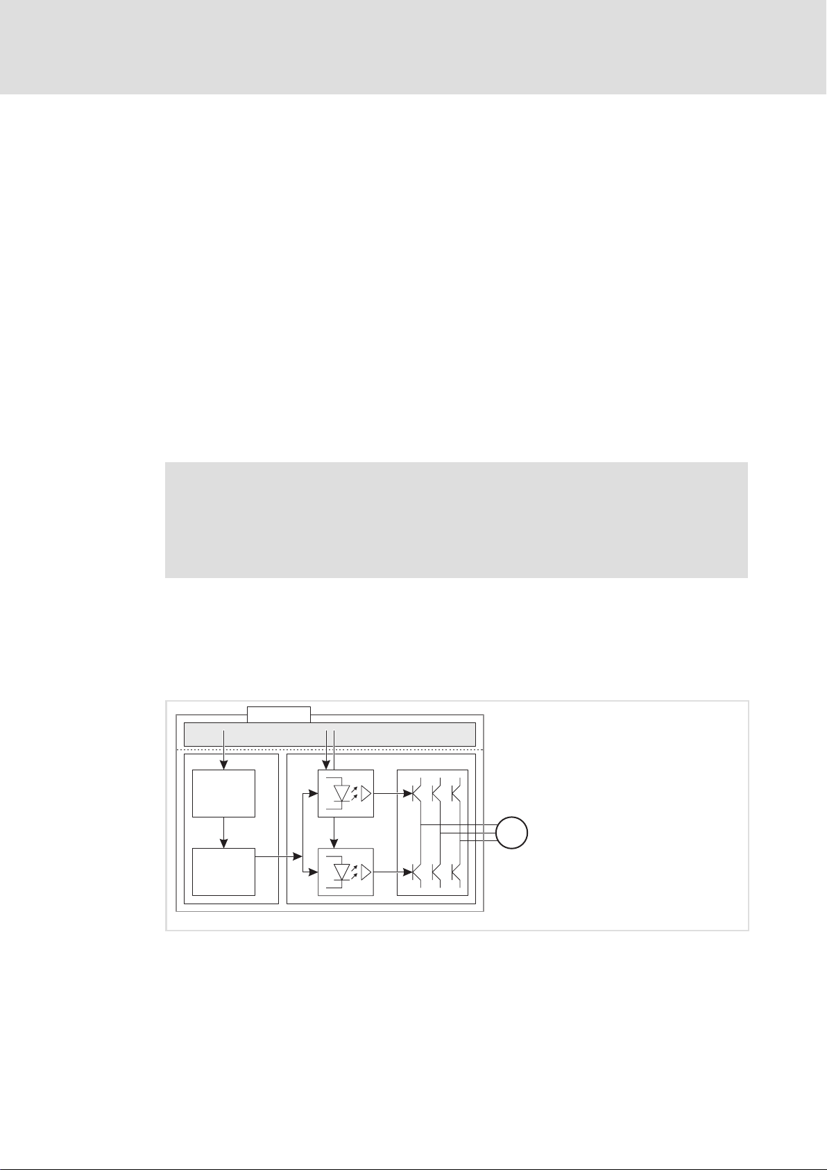
3.1.2 Disconnecting paths
The transmission of the pulse width modulation is safely switched (off) by the safety unit.
After this, the power drivers do not generate a rotating field. The motor is safely switched
to torqueless operation (STO).
14
E84DPSO02
Fig. 3−1 Operating principle of safety unit
SO Safety option 10, 20, or 30
xxx Control terminals used in safety engineering systems or safety bus
C Control section
mC Microcontroller
PWM Pulse width modulation
P Power section
M Motor
l
EDS84DPSO01 EN 2.1
Page 15

3.1.3 Safety status
When the controller is disconnected from the safety unit, the "Safe torque off" (STO) status
is set (C00155 bit 10 = 1).
3.1.4 Fail−safe status
When internal errors of the safety unit are detected, the motor is safely switched to
torqueless operation (fail−safe status).
Safety option 10
Operating mode
Safety status
3
EDS84DPSO01 EN 2.1
l
15
Page 16
3
Safety option 10
Status display
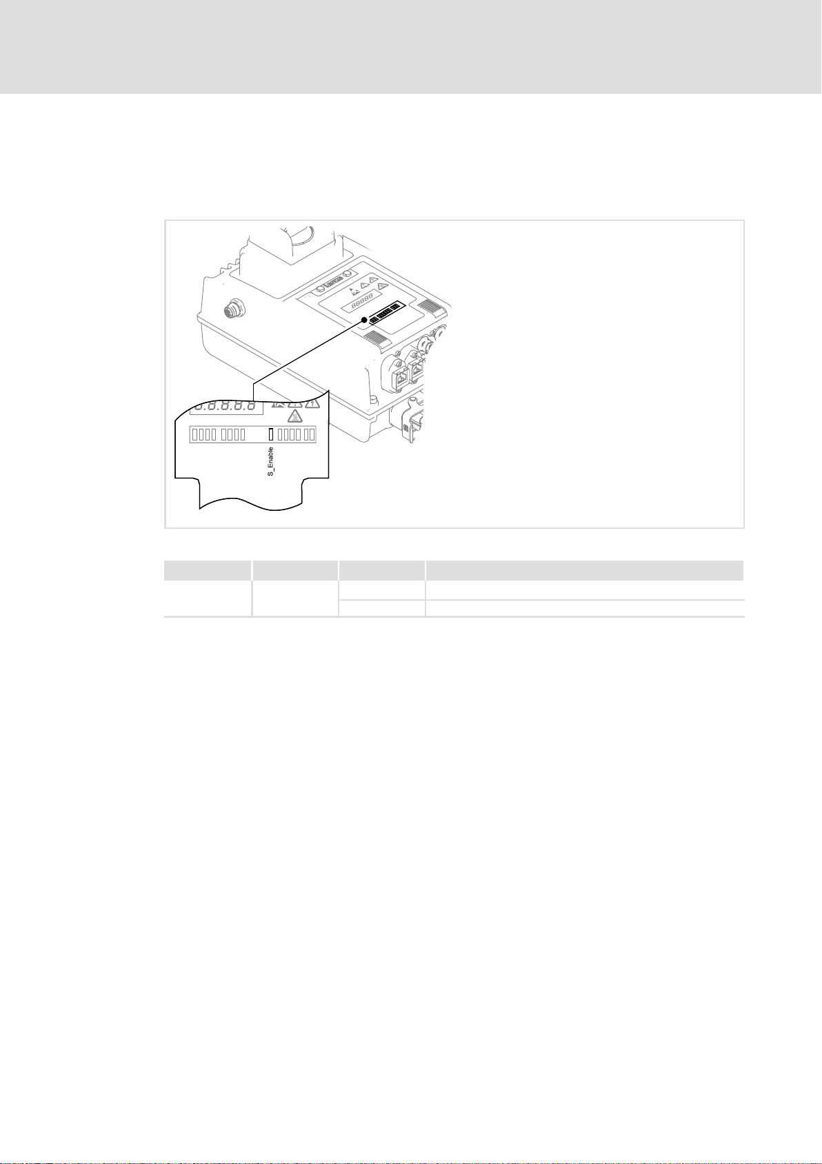
3.2 Status display
The operating status of the "STO" safety function is displayed using an LED on the front of
the controller.
Fig. 3−2 Position of the LED for the drive−based safety on the device
Pos. Colour State Description
S−Enable yellow
The status of safety option 10 is solely shown via the "S−Enable" display. All other displays have no function.
on Controller is enabled
blinking Safety function is active (non−safe display)
E84DPSO06 SO10
16
l
EDS84DPSO01 EN 2.1
Page 17

3.3 Technical data
Supply
The safe input and the output are isolated and designed for a low−voltage supply through
a safely separated power supply unit (SELV/PELV) of 24 V DC. P/N switching input signals
and test pulses £ 1 ms are permissible.
Active sensors are directly connected to the X61 circular connector.
Passive sensors are connected to the X61 circular connector via a switching device. The
switching device must comply with the required performance level of the application.
There is no monitoring for short circuits.
Detailed features of the inputs and outputs of the safety unit
Terminal Specification [Unit] min. typ. max.
SIA, SIB
GI GND potential for SIA / SIB and for the non−safe
24O Supply voltage through safely separated power supply
DO
24O, DO Output current A 0.2
Safety option 10
Technical data
Low signal
High signal
Input capacitance at switch−off
Input delay (tolerated test pulse)
Switch−off time (depending on the controller)
Running time
Input current mA 45 50
Input capacitance at switch−on, reduced
signalling output
unit (SELV/PELV)
Low signal
High signal
V −3 0 5
V 18 24 30
nF 3
ms 1
ms 2.5 4
ms 3
mF 22
V 18 24 30
V 0 0.8
V 18 24 30
3
Truth table
EDS84DPSO01 EN 2.1
Safe input / channel Signalling
SIA SIB DO1/DO Description of device status Enable
001
0 1 0 0
1 0 0 0
1 1 0 Drive active 1
output
"Safe torque off" activated
Controller
) Note!
Safe inputs have two channels (...A/...B). The channels must be triggered
separately and simultaneously (equivalent).
Active triggering of only one channel indicates faulty sensors or impermissible
wiring.
Despite this, the integrated safety system is activated as soon as at least one
channel has been triggered.
l
0
17
Page 18
3
Safety option 10
Electrical installation
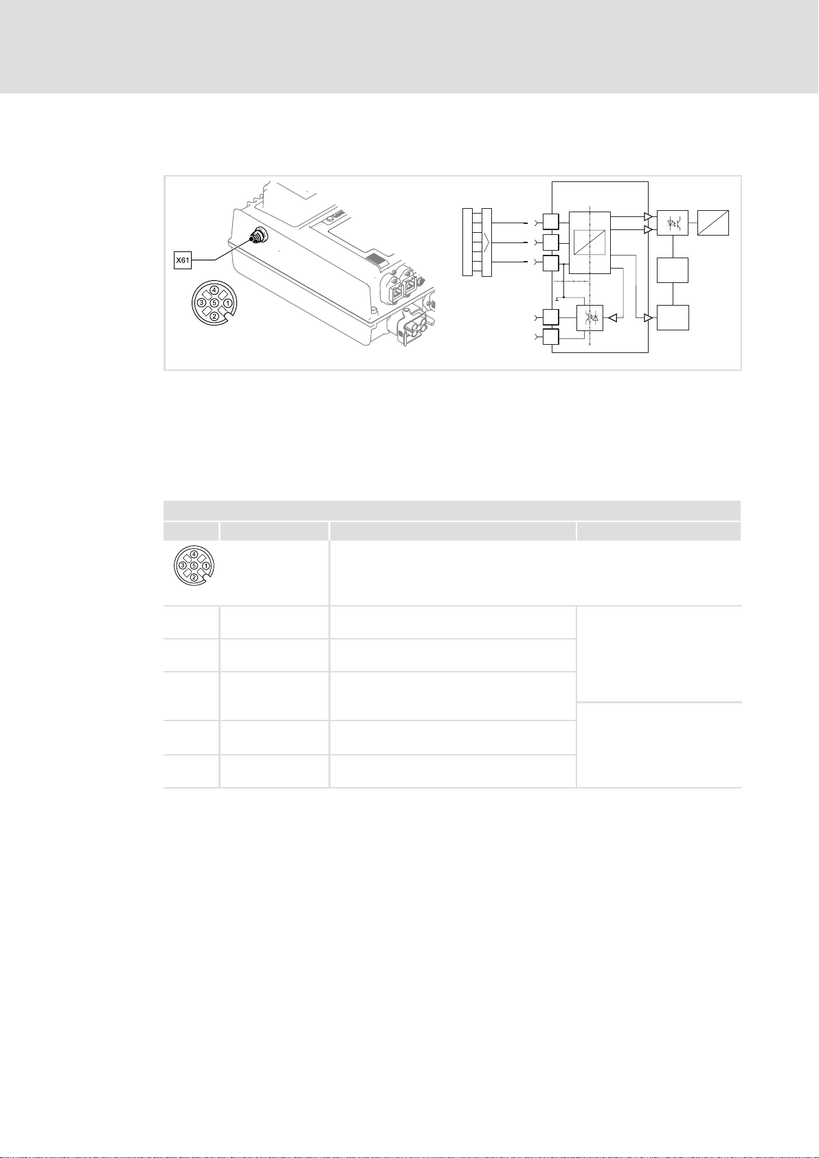
3.4 Electrical installation
SO
SIA
-
SIB
GI
DO1
24O
E84DPSO005 E84DPSO03
Fig. 3−3 Block diagram − safe torque off (STO)
SO Safety option 10
X61 M12 circular connector for safety engineering systems
SIA, SIB, GI Connections for shutdown paths
24O, DO1 Feedback connections
mC Microcontroller
PWM Pulse width modulation
X61 − connection of safety system "Safety Option 10"
Pin Connection Description Data
M12, 5−pole pins, A−coded
84DPSO05_5
1 SIA Safe input, channel A
I
typ
LOW: −3 ... 5 V
2 SIB Safe input, channel, B
HIGH: 18 ... 30 V
Supply through safely
separated power supply unit
5 GI 1. GND potential for SIA/SIB
(SELV/PELV).
2. GND potential for the non−safe signalling
output
4 24O 24−V voltage supply for the non−safe signalling
output
3 DO1 Non−safe signalling output: "SafeTorqueOff"
with 2−channel request by SIA and SIB
24 V, max. 0.2 A
short−circuit−proof
Supply through safely
separated power supply unit
(SELV/PELV).
High active
~
-
PWM
µC
= 45 mA
18
l
EDS84DPSO01 EN 2.1
Page 19

3.5 Certification
I Tip!
The "TÜV Rheinland Group" certificate is available on the Internet under:
http://www. Lenze.com
Safety option 10
Certification
3
EDS84DPSO01 EN 2.1
l
19
Page 20

4
Safety option 20
Operating mode
Introduction
4 Safety option 20
4.1 Operating mode
4.1.1 Introduction
Due to safety option 20, the following safety functions can be used:
ƒ Safe torque off (STO),
formerly: safe standstill
ƒ Safe stop 1 (SS1)
ƒ Safe stop emergency (SSE)
ƒ Safe operation mode selector (OMS)
ƒ Safe enable switch (ES)
The safe disconnection of the drive is achieved through:
ƒ a higher−level safety PLC via PROFIsafe/PROFINET
ƒ a higher−level safety PLC via PROFIsafe/PROFIBUS
The functions of the safety option must be parameterised via the »Engineer«.
The motion functions are continued to be executed by the controller. The drive−based
safety monitors the safe compliance with the limit values. When the limit values are
exceeded, the drive−based safety starts the control functions according to EN 60204−1
directly in the controller.
The safety functions are suitable for applications according to IEC 61508 to SIL 3 and
achieve a performance level (PL) e and the control category 3 according to EN ISO 13849−1.
20
l
EDS84DPSO01 EN 2.1
Page 21

4.1.2 Disconnecting paths
M
SO
PWM
µC
PC
3x
3x
Xxx
The transmission of the pulse width modulation is safely switched (off) by the safety unit.
After this, the power drivers do not generate a rotating field. The motor is safely switched
to torqueless operation (STO).
Fig. 4−1 Operating principle of safety unit
SO Safety option 10, 20, or 30
xxx Control terminals used in safety engineering systems or safety bus
C Control section
mC Microcontroller
PWM Pulse width modulation
P Power section
M Motor
Safety option 20
Operating mode
Disconnecting paths
4
E84DPSO02
4.1.3 Safety status
When the controller is disconnected from the safety unit, the "Safe torque off" (STO) status
is set (C00155 bit 10 = 1).
4.1.4 Fail−safe status
When internal errors of the safety unit are detected, the motor is safely switched to
torqueless operation (fail−safe status).
EDS84DPSO01 EN 2.1
l
21
Page 22

4
Safety option 20
Status display
4.2 Status display
Light−emitting diodes (LED) on the front of the controller display the operating status of
the safety engineering system.
Pos. Colour State Description
on
S−State green
S−Error red
S−Acknw yellow on A parameter set acceptance must be acknowledged
S−Enable yellow
blinking Drive−based safety is in service status
off
on Fault, trouble or warning
blinking
off Error−free operation
on Controller is enabled
blinking Safety function is active (non−safe display)
Communication between standard device and safety system
is running
Communication between standard device and safety system
is not possible
Drive−based safety is not accepted by the standard device
E84DPSO06 SO20
22
l
EDS84DPSO01 EN 2.1
Page 23

4.3 Technical data
Safety option 20 is exclusively controlled via the safety bus. Supply voltages, signal levels
etc. of the used safety bus system are relevant.
Since there are no inputs or outputs at the application end, connection data need not be
specified.
Safety option 20
Technical data
4
EDS84DPSO01 EN 2.1
l
23
Page 24

4
4.4 Electrical installation
Safety option 20
Electrical installation
Safety option 20 does not require external wiring because the safety functions are
exclusively controlled via the used safety bus.
24
l
EDS84DPSO01 EN 2.1
Page 25

4.5 Certification
I Tip!
The "TÜV Rheinland Group" certificate is available on the Internet under:
http://www. Lenze.com
Safety option 20
Certification
4
EDS84DPSO01 EN 2.1
l
25
Page 26

4
4.6 Safety functions
Safety option 20
Safety functions
The available safety functions comply with the safety functions of safety option 30
(¶ 45). However, the safety engineering system is exclusively controlled via the safety
bus. Therefore, the controller with safety option 20 is not provided with connections for
safety sensors.
26
l
EDS84DPSO01 EN 2.1
Page 27

4.7 Safe parameter setting
) Note!
Safety−relevant parameters can exclusively be transmitted to the drive−based
safety by safe parameter setting using the »Engineer«.
The parameter set is saved to the memory module and the drive−based safety
with a definite module ID which must comply with the effective safety address
in the drive−based safety.
The following is required for the parameterisation and configuration of the safety option:
ƒ A computer with a Windows® operating system (XP or 2000)
ƒ The Lenze »Engineer« PC software
ƒ Connection with the controller via an interface.
– diagnostic interface X70 with diagnostic USB adapter
– PROFINET
– Ethernet
Safety option 20
Safe parameter setting
Parameter setting
4
Further information and help can be found in:
ƒ the online help of the controller with safety option
ƒ the 8400 protec software manual, integrated safety system ...,
order designation: EDS84DWTSO
4.7.1 Parameter setting
Safety−relevant parameters can exclusively be transmitted to the drive−based safety by
safe parameter setting. The parameter set is saved to the memory module and the
drive−based safety with a definite module ID which must comply with the effective safety
address in the drive−based safety.
Safe parameter setting requires the service status. The service status means:
ƒ The standard stop is active and the drive is safely switched to torqueless operation
(STO).
ƒ The communication via the safety bus is active but passivated.
About the service status:
ƒ It can be activated by the Lenze »Engineer« PC software.
ƒ It can be quit by reinitialising the drive−based safety, i.e. the communication via the
safety bus is interrupted.
EDS84DPSO01 EN 2.1
) Note!
The service status also occurs if the parameter set in the memory module does
not comply with the parameter set in the drive−based safety during
initialisation.
l
27
Page 28

4
4.7.1.1 Parameter setting with the Lenze »Engineer« PC software
Safety option 20
Safe parameter setting
Parameter setting
Safe parameter setting is supported by the Lenze »Engineer« PC software as of
version 2.10.
The parameter setting is described in the software manual of drive−based safety for 8400
protec controllers. In addition, the software provides comprehensive online help.
Password
To store a safe parameter set, a password is required. The standard password is: "Lenze
SM301". The password can be changed and must have at least six characters.
Use "General reset" to delete the safe parameter set in the memory module and the
drive−based safety. The drive−based safety must be reparameterised.
The password is reset to the standard "Lenze SM301".
28
l
EDS84DPSO01 EN 2.1
Page 29

4.7.1.2 Parameter set transfer from the memory module
The safe parameter set transfer is supported by a safe parameter set saved to the memory
module, e.g. when replacing the standard device or parameterising the drive−based safety,
without the Lenze »Engineer« PC software via the memory module.
ƒ A valid parameter set with a corresponding module ID must be stored.
ƒ The drive−based safety must be in the service status.
ƒ Open the service hatch on the standard device to be able to operate the "T1" and
"T2" pushbuttons.
The transfer of the parameter set from the memory module must be acknowledged with
the pushbuttons:
ƒ the drive−based safety is in the service status
– the "S_State" LED is blinking
– the "S_Error" LED is lit
– the "S_Acknw" LED is lit
– the "S_Enable" LED is blinking
Safety option 20
Safe parameter setting
Parameter setting
4
ƒ press and hold the "T1" and "T2" pushbuttons at the same time
ƒ the "S_Acknw" LED starts blinking
ƒ if the "S_Acknw" LED goes out, release both pushbuttons immediately
ƒ after a few seconds, the "S_Acknw" LED is lit again
ƒ press and hold the "T1" and "T2" pushbuttons at the same time again
ƒ the "S_Acknw" LED starts blinking
ƒ if the "S_Acknw" LED goes out, release both pushbuttons immediately
ƒ The parameter set transfer is completed successfully.
If system−related response times (approx. 2.5 s) cannot be complied with, the parameter
transfer is cancelled. The process must be started again.
In case of success, the parameter transfer is recorded in the logbook of the standard device
and the service status is quit by a software restart.
If the parameter set is invalid, an error is indicated and the "S_Error" LED is lit.
I
AS
0
I
S82
0
t
max
Fig. 4−2 Acknowledgement procedure
AS "S_Acknw" LED
S82 "Left" and "Right" pushbuttons at the same time
t Time axis
t
max
t
max
Maximum permissible response time
t
t
max
SM301DIA_P
EDS84DPSO01 EN 2.1
l
29
Page 30

4
4.7.2 Parameter sets and axes
Safety option 20
Safe parameter setting
Parameter sets and axes
The unambiguousness of an axis with safety functions in a drive system can be achieved
by means of the safety address. In the safe parameter set a module ID is stored. This
module ID is compared to the effective safety address (C15112) in the drive−based safety.
When a drive−based safety is initialised, e.g. when loading the parameter set, the
compliance of the safety address will be checked. If no compliance exists, an initialisation
error is reported.
) Note!
ƒ Clearly define the safety address in a drive system or plant.
ƒ Document the address in circuit diagrams and labels.
ƒ Ensure identical settings when replacing the standard device or the memory
module.
In drive systems with activated safety bus the safety address is also used as the safety bus
target address. The clear assignment of the safety address must be configured in the safety
PLC.
In drive systems without activated safety bus, unambiguousness and correct assignment
of the safety address must be checked. For this purpose, use the Lenze »Engineer« PC
software or an EZAEBK200x diagnosis terminal.
30
l
EDS84DPSO01 EN 2.1
Page 31

4.8 Error management
4.8.1 Error states
Detected errors or maloperation of the drive are assigned to error states with definite
reactions. The reaction can be co−ordinated with the complete drive via the error states.
Safety option 20
Error management
Error states
4
Features
System error Trouble Warning
Event Fatal internal error Fault Monitoring function
"S_State" LED is lit is lit is lit
Status of drive−based
safety
The control category
according to EN 954−1 ...
Reaction The motor immediately
Acknowledgement after
deactivated event
Tab. 4−1 Overview of error states
Lockout (CPU stopped) Error status Normal operation
... has been abandoned ... has been abandoned ... has not been abandoned
switches to torque−free
operation via
l STO
l Connection and
disconnection of the
24−V supply at the
safety module
Error status
The motor is stopped via
l STO or
l SS1
l Error acknowledgement (AIE) via X62 (positive
signal pulse with a signal duration of 0.3 ... 10 s)
l Fault acknowledgement (AIE) via the safety bus
(Bit "PS_AIE")
l Connection and disconnection of the 24−V supply at
the safety module
) Note!
If the system fault also occurs after switching the 24−V supply, please contact
the service.
When using PROFIsafe as safety bus:
ƒ If faults occur in the PROFIsafe communication, the data is passivated by the
PROFIsafe driver.
ƒ After the PROFIsafe communication is reinitialised, the drive is automatically
enabled again if no standstill function is selected.
ƒ Events which cause an error status are sent as diagnostic telegram via the safety
bus.
4.8.2 Logbook
Error states are saved in the logbook of the standard device. The following is entered:
ƒ Type of response (e.g. trouble, warning, or information) to the event
ƒ Module which has caused the event (e.g. MCTRL or TEMPCONTROL)
ƒ Date/time (in case of memory module with real−time clock)
ƒ Value of the power−on time meter
The available logbook entries can be displayed in the »Engineer« when an online
connection has been established.
EDS84DPSO01 EN 2.1
l
31
Page 32

4
Safety option 20
Response times
4.9 Response times
In order to detect the response time to a safety function the entire system must be
considered. The following is relevant:
ƒ Response time of the connected sensors.
ƒ Input delay of the safety inputs.
ƒ Internal processing time.
ƒ When using PROFIsafe as safety bus:
– Monitoring time for the cyclic service in the PROFIBUS/PROFINET.
– Monitoring time of the PROFIsafe in the safety PLC.
– Processing time in the safety PLC.
ƒ Delay times due to further components.
S
0
1
t
t
1
t
i
2
μC
t
3
t
5
SF
t=0
t
ps
3
2
t
4
μC
Fig. 4−3 Response times to the request of a safety function
0 Standard device
1 Drive−based safety
2 Safety PLC
3 Safety bus
mC Microcontroller
S Safety sensor technology
SF Activated safety function
lcu12x_352
32
l
EDS84DPSO01 EN 2.1
Page 33

Safety option 20
Response times
Response times of the inputs
4
4.9.1 Response times of the inputs
Response time to an event in the sensors
Time interval (Fig. 4−3) [ms]
t1Response time of the sensors according to manufacturer
t
Input delay of the safe inputs
2
tiProcessing time in drive−based safety 4
Safety function starts after ... S
Tab. 4−2 Response time to an event in the sensors
C15034:
Input error:
information
0 ... 100
2
EDS84DPSO01 EN 2.1
l
33
Page 34

4
Safety option 20
Response times
Response times of the safety bus
4.9.2 Response times of the safety bus
PROFIsafe
Response time to an event in the safety sensors (PROFIsafe input data)
Time interval (Fig. 4−3) [ms]
t1Response time of the sensors according to manufacturer
t
Input delay of the safe inputs
2
t3Processing time in drive−based safety 24
PROFIsafe input data ready for transmission to ... S
tPsPROFIsafe cycle time according to manufacturer
PROFIsafe input data ready for processing in the safety PLC ... S
Tab. 4−3 Response time to an event in the sensors
Response time to a PROFIsafe control word (PROFIsafe output data)
Time interval (Fig. 4−3) [ms]
t4Processing time in the safety PLC must be calculated
tPsPROFIsafe cycle time according to manufacturer
t5Processing time in drive−based safety 14
Safety function starts after ... S
Tab. 4−4 Response time in case of PROFIsafe request
C15034:
Input error:
information
0 ... 100
2
information
information
Information on how to calculate the processing time and transmission time of the
PROFIsafe can be found in the documentation of the safety PLC used.
) Note!
If PROFIsafe communication is troubled, the fail−safe status will be reached
after the PROFIsafe monitoring time (F_WD_Time) has expired. PROFIsafe
communication is passivated.
Example
ƒ After an event has occurred at a safe input, the message is fed back to drive−based
safety via the safety PLC.
ƒ Drive−based safety activates a safety function.
ƒ Hence, the maximum response time to the event is calculated as follows:
t
max response
When calculating the maximum response time, include the times of the safety functions,
e.g. in case of SS1 the stopping time (30 s) until STO is active.
= t1 + t2 + t3 + max {tWD; tPS + t4 + tPs + t5}
34
l
EDS84DPSO01 EN 2.1
Page 35

5 Safety option 30
5.1 Operating mode
5.1.1 Introduction
Due to safety option 30, the following safety functions can be used:
ƒ Safe torque off (STO),
formerly: safe standstill
ƒ Safe stop 1 (SS1)
ƒ Safe stop emergency (SSE)
ƒ Safe operation mode selector (OMS)
ƒ Safe enable switch (ES)
The safe disconnection of the drive is achieved through:
Safety option 30
Operating mode
Introduction
5
ƒ a higher−level safety PLC via PROFIsafe/PROFINET
ƒ connected active or passive sensors
The functions of the safety option must be parameterised via the »Engineer«.
The motion functions are continued to be executed by the controller. The drive−based
safety monitors the safe compliance with the limit values. When the limit values are
exceeded, the drive−based safety starts the control functions according to EN 60204−1
directly in the controller.
The safety functions are suitable for applications according to IEC 61508 to SIL 3 and
achieve a performance level (PL) e and the control category 3 according to EN ISO 13849−1.
EDS84DPSO01 EN 2.1
l
35
Page 36

5
M
SO
PWM
µC
PC
3x
3x
Xxx
Safety option 30
Operating mode
Disconnecting paths
5.1.2 Disconnecting paths
The transmission of the pulse width modulation is safely switched (off) by the safety unit.
After this, the power drivers do not generate a rotating field. The motor is safely switched
to torqueless operation (STO).
Fig. 5−1 Operating principle of safety unit
SO Safety option 10, 20, or 30
xxx Control terminals used in safety engineering systems or safety bus
C Control section
mC Microcontroller
PWM Pulse width modulation
P Power section
M Motor
E84DPSO02
5.1.3 Safety status
When the controller is disconnected from the safety unit, the "Safe torque off" (STO) status
is set (C00155 bit 10 = 1).
5.1.4 Fail−safe status
When internal errors of the safety unit are detected, the motor is safely switched to
torqueless operation (fail−safe status).
36
l
EDS84DPSO01 EN 2.1
Page 37

Safety option 30
Operating mode
Safe inputs
5
5.1.5 Safe inputs
Contact function test
) Note!
Make sure that an internal contact function test is carried out at the safe
inputs:
Safe input in the ON state
ƒ A LOW level at one channel puts the input in the OFF state. The discrepancy
ƒ A LOW level must be detected at both channels within the discrepancy time,
ƒ To be able to acknowledge the discrepancy error, a LOW level must be
Safe input in the OFF state
ƒ A HIGH level at one channel starts the discrepancy monitoring.
ƒ A HIGH level must be detected at both channels within the discrepancy
ƒ To be able to acknowledge the discrepancy error, a HIGH level must be
monitoring starts simultaneously.
otherwise a discrepancy error will be reported.
detected before at both channels.
time, otherwise a discrepancy error will be reported.
detected before at both channels.
ON state
Value of safe input:
ON state
Switch both channels
to ON state
Discrepancy monitoring Discrepancy monitoring
Value of safe input:
OFF state
One channel in
ON state
OFF state
Value of safe input:
OFF state
Fig. 5−2 Status behaviour − contact function test
One channel in
OFF state
Value of safe input:
OFF state
Switch both channels
to OFF state
SSP94SM355
EDS84DPSO01 EN 2.1
l
37
Page 38

5
Safety option 30
Operating mode
Safe inputs
A
B
C
D
Fig. 5−3 Contact function test − error−free input signals
A
B
C
D
AIE
Fig. 5−4 Contact function test − faulty input signals
A, B Safe input, channel A and channel B
C Internal valuation of the safe input
D Discrepancy monitoring
AIE Fault acknowledgement
Discrepancy monitoring active
Discrepancy monitoring − time−out
Fault acknowledgement impermissible
Fault acknowledgement permissible
SSP94SM358_1
SSP94SM358_2
38
l
EDS84DPSO01 EN 2.1
Page 39

5.2 Status display
Light−emitting diodes (LED) on the front of the controller display the operating status of
the safety engineering system.
Safety option 30
Status display
5
Pos. Colour State Description
on
S−State green
S−Error red
S−Acknw yellow on A parameter set acceptance must be acknowledged
S−Enable yellow
blinking Drive−based safety is in service status
off
on Fault, trouble or warning
blinking
off Error−free operation
on Controller is enabled
blinking Safety function is active (non−safe display)
Communication between standard device and safety system
is running
Communication between standard device and safety system
is not possible
Drive−based safety is not accepted by the standard device
E84DPSO06 SO30
EDS84DPSO01 EN 2.1
l
39
Page 40

5
Safety option 30
Technical data
5.3 Technical data
24 V supply
The safety option 30 component does not require an external supply voltage.
Inputs and outputs
The inputs are isolated and designed for a low−voltage supply of 24 V DC.
Detailed features of the safe inputs
Terminal Specification [Unit] min. typ. max.
I1A, I1B
I2A, I2B
AIE, AIS
AIE, AIS Input delay (operating time) s 0.3 10
24I Voltage supply only for AIE and AIS V 24
CLA, CLB
PLC input, IEC−61131−2, 24 V, type 1
Low signal input voltage
Input current at low signal mA 15
High signal input voltage
Input current at high signal mA 2 15
Input capacitance
Repetition rate of the test pulses
PLC output, IEC−61131−2, 24 V DC, 50 mA
Low signal output voltage
High signal output voltage
Output current
Cable capacity
Cable resistance of a passive sensor
V −3 0 5
V 15 24 30
nF 3.5
ms 50
V 0 0.8
V 17 24 29
mA 60
nF 100
W 200
Safety option 30 does not provide any safe outputs.
40
l
EDS84DPSO01 EN 2.1
Page 41

5.4 Electrical installation
Principle circuit diagram
Safety option 30
Electrical installation
AIE
1
24_ACK
2
AIS
3
GND-SM
4
GND-SM
5
X62
5
E84Dx...-x xxS
CLA
1
CLB
2
GND-CLK
S3
S1
E84DxWT... 8400 protec controller with safety option 30
S1 Passive sensor with channel A and B (at X64 in our example)
S3 Higher−level safety control (active sensor)
S4 Lightgrid (active sensor) (at X63 in our example)
3
S4
I1A
4
GND-I1
5
I1B
6
GND-CLK
7
GND-I1
8
CLA
1
CLB
2
GND-CLK
3
I2A
4
GND-I2
5
I2B
6
GND-CLK
7
GND-I2
8
L
X63
X64
84DPSSO031
EDS84DPSO01 EN 2.1
l
41
Page 42

5
Safety option 30
Electrical installation
Terminal assignment
} Danger!
Danger to life through improper installation
Improper installation of the safety engineering systems can cause
anuncontrolled starting action of the drives.
Possible consequences:
ƒ Death or severe injuries
Protective measures:
ƒ The installation of the cables between X62, X63, and X64 and the connected
components must be shielded:
– Attach the shield at least in the connector shell.
– Also attach the shield to the connected component if possible.
X62 − connection of safety engineering system "Safety Option 30"
Pin Connection Description Data
M12, 5−pole sockets, A−coded
84DPSO05_5
1 AIE Error acknowledgement
2 24_ACK 24−V supply voltage for reset button max. 300 mA
3 AIS Restart acknowledgement
4 GND_SM
5 GND_SM
GND potential
42
l
EDS84DPSO01 EN 2.1
Page 43

Safety option 30
Electrical installation
X63 − connection of the "Safety Option 30" safety engineering system
Pin Connection Description Data
M12, sockets 8−pole, A−coded
84DSO05_8
1 CLA Clock output, channel A
2 CLB Clock output, channel B
3 GND_CLK GND potential − clock output, channel A
4 I1A Safe input 1, channel A
5 GND_I1 GND potential − input 1, channel A
6 I1B Safe input 1, channel B
7 GND_CLK GND potential − clock output, channel B
8 GND_I1 GND potential − input 1, channel B
X64 − connection of the "Safety Option 30" safety engineering system
Pin Connection Description Data
M12, sockets 8−pole, A−coded
5
84DSO05_8
1 CLA Clock output, channel A
2 CLB Clock output, channel B
3 GND_CLK GND potential − clock output, channel A
4 I2A Safe input 2, channel A
5 GND_I2 GND potential − input 2, channel A
6 I2B Safe input 2, channel B
7 GND_CLK GND potential − clock output, channel B
8 GND_I2 GND potential − input 2, channel B
EDS84DPSO01 EN 2.1
l
43
Page 44

5
5.5 Certification
Safety option 30
Certification
I Tip!
The "TÜV Rheinland Group" certificate is available on the Internet under:
http://www. Lenze.com
44
l
EDS84DPSO01 EN 2.1
Page 45

5.6 Safety functions
5.6.1 Safe torque off
Safe Torque Off/STO
This function corresponds to a "Stop 0" according to EN 60204.
When this function is used, the power supply of the motor is immediately (t1) safely
interrupted. The motor cannot create a torque and thus no dangerous movements of the
drive can occur. Additional measures, e.g. mechanical brakes are needed against
movements caused by external force.
I
0
0
n
Safety option 30
5
Safety functions
Safe torque off
t
1
0
t1
t1
2
I
STO
0
0 Input signal of the request of a safety function
I ON state
O OFF state
1 Speed characteristic n of the motor
t Time axis
tx Action instant
2 Feedback(s)
The restart behaviour can be set (C15300/1). Function sequence and error response have
no adjustable parameters.
t
t
SM301DIA_STO
} Danger!
If the request for the safety function is cancelled, the drive will restart
automatically.
You must provide external measures which ensure that the drive only restarts
after a confirmation (EN 60204).
EDS84DPSO01 EN 2.1
l
45
Page 46

5
Safety option 30
Safety functions
Safe torque off
Activation
How to activate the function:
ƒ "OFF state" at a safe input, the function of which has been assigned by parameter
setting.
ƒ Via a safety bus data telegram with corresponding content.
ƒ As response to the error stop request.
ƒ As response to the emergency stop request if the function has been parameterised
as emergency stop function (C15205).
46
l
EDS84DPSO01 EN 2.1
Page 47

Safety option 30
Safety functions
Safe stop 1
5
5.6.2 Safe stop 1
Safe Stop 1 / SS1
This function corresponds to a "Stop 1" according to EN 60204.
The function monitors the reaching of the speed n = 0 (C15310) within an adjustable
stopping time (C15305). The speed is calculated from the encoder data (safe speed
measurement). Without encoder the function evaluates the speed status n = 0 from the
standard device. For this, the monitored stopping time parameterised in the safety module
must be 0.5 s longer than the stopping time in the controller.
When the stopping time (t2) has elapsed, the power supply of the motor is immediately
safely interrupted (STO). The motor cannot create a torque and thus no dangerous
movements of the drive. If a standstill was not reached, an error message is caused
additionally.
Additional measures, e.g. mechanical brakes are needed against movements caused by
external force. The time for a brake to be applied must be considered when defining the
stopping time.
A restart is only possible after the stopping time has elapsed.
I
0
1
2
SS1
STO
0
n
0
I
0
I
0
t
S
t1 t2
t1
0 Input signal of the request of a safety function
I ON state
0 OFF state
1 Speed characteristic n of the motor
t Time axis
tx Action instant
Monitored stopping time
t
S
–– Normal operation
−−− Incorrect operation
2 Feedback(s)
t
t
t
t
SM301DIA_SS1
EDS84DPSO01 EN 2.1
l
47
Page 48

5
Safety option 30
Safety functions
Safe stop 1
Activation
How to activate the function:
ƒ "OFF state" at a safe input, the function of which has been assigned by parameter
setting.
ƒ Via a safety bus data telegram with corresponding content.
ƒ As response to the error stop request.
ƒ As response to the emergency stop request if the function has been parameterised
as emergency stop function (C15205).
48
l
EDS84DPSO01 EN 2.1
Page 49

Safety option 30
Safety functions
Emergency stop
5
5.6.3 Emergency stop
Safe Stop Emergency/SSE
The emergency stop function activates STO or SS1. The function to be executed can be
adjusted (C15205). In special operation, the emergency stop cannot be avoided.
) Note!
Connect the emergency stop buttons which must not be overruled by a special
operation to the emergency stop function. For this purpose, parameterise the
safe input as "emergency stop" (C15031).
The emergency stop function can also be requested with SSE bit via the safety
bus.
The activation of the function is reported internally to the standard device and via the
safety bus of the higher−level control.
Activation
How to activate the function:
ƒ "OFF state" at a safe input, the function of which has been assigned by parameter
setting.
ƒ Via a safety bus data telegram with corresponding content.
EDS84DPSO01 EN 2.1
l
49
Page 50

5
Safety option 30
Safety functions
Safe operation mode selector
5.6.4 Safe operation mode selector
Operation Mode Selector / OMS
The function provides a special operation of the drive. In the special operation the drive is
stopped (status 2). The drive can be traversed in the special operation via an enable switch
(status 3).
For the stop status in the special operation, the STO or SS1 functions can be parameterised.
For motion functions in the special operation, the free movement can be parameterised.
The parameterised monitoring function will be automatically activated with the transition
to the special operation.
The special operation enables an override of the simple STO and SS1 stop functions by the
enable switch.
An active emergency stop function is also executed in special operation.
The special operation can also be selected via the safety bus by the F−PLC, unless a safe
input is parameterised as operation mode selector.
The return to normal operation is only possible in the stop status. Since the drive is stopped
in status 2, the AIS acknowledgement is required for restart. The parameters for the restart
STO/SS1 are used.
) Note!
When returning to normal operation, the automatic restart is not permissible.
If "automatic restart" is parameterised, this can be prevented by special
measures, e.g. programming in the higher−level control.
) Note!
The "safe enable switch" function serves to directly cancel/complete the
stopping times assigned to the stop functions.
) Note!
If an error (e.g. a discrepancy error) occurs at a safe input to which the OMS
function has been assigned, normal operation will be selected. This
corresponds to the OFF state. The "S_Error" LED is lit and STO is not activated.
The special operation can only be selected again when the error has been
eliminated and acknowledged.
50
l
EDS84DPSO01 EN 2.1
Page 51

Safety option 30
Safety functions
Safe operation mode selector
Preconditions
A safe input must be parameterised and interconnected as operation mode selector. You
can only connect and parameterise an operation mode selector. The OMS bit of the safety
bus must be deactivated (C15113).
The special operation can also be selected via the safety bus with the OMS bit, unless a safe
input is set as operation mode selector.
The plausibility check rejects ambiguous settings until they are parameterised correctly.
) Note!
The "free traversing" setting for the special operation (C15201) motion
function must be suitable for the application!
Activation
How to activate the function:
ƒ Via a safe input which has been assigned to the function by parameterisation. In
addition, the requested operating mode depends on OMS: Function at LOW level
(C15202).
Example:
Normal operation at LOW level
The special operation is activated via a key−operated switch. The "Special operation
with LOW level" function is not permissible for a key−operated switch which uses the
special operation for short−circuiting purposes. An open circuit in the cable of the
switch would activate the special operation which is otherwise only possible with a key.
Special operation at LOW level
The special operation is active if a safety grid (safety door) is openend, i.e. the safe input
provides a LOW level and executes the parameterised stop function.
5
Only if no safe input is used, the function can only be activated via the safety bus:
ƒ A data telegram with corresponding contents must be transmitted to the standard
device.
EDS84DPSO01 EN 2.1
l
51
Page 52

5
Safety option 30
Safety functions
Safe enable switch
5.6.5 Safe enable switch
Enable Switch / ES
The drive can be traversed in special operation using an enable switch (see operation mode
selector).
Operating mode Normal Special
Event Impact Impact
− Status −
Request − OMS special operation via ...
... safe input Change W Status
... safety bus same response − only possible as an alternative to the safe input
Request − ES confirmation via ...
... safe input No function Status
... via safety bus same response − only possible as an alternative to the safe input
Stop request Status
Emergency stop Status
SM301OMS01
Stop function ...
l STO
l SS1
... is executed
Activated monitoring functions
remain active.
l Free movement
is not executed
parameterised function ...
l STO
l SS1
... is executed
parameterised function ...
l STO
l SS1
... is executed
52
l
EDS84DPSO01 EN 2.1
Page 53

Safety option 30
Safety functions
Safe enable switch
Preconditions
A safe input must be parameterised and interconnected as enable switch. You can only
connect and parameterise one enable switch. The ES bit of the safety bus must be
deactivated (C15113).
The enable switch function can also be selected via the safety bus with the ES bit, unless
a safe input is parameterised as enable switch.
The special operation must be activated.
The plausibility check rejects ambiguous settings until they are parameterised correctly.
Activation
How to activate the function:
ƒ Via a safe input which has been assigned to the function by parameterisation. In
addition, the requested operating mode depends on OMS: Function at LOW level
(C15202).
Example:
Normal operation at LOW level
The special operation is activated via a key−operated switch. The "Special operation
with LOW level" function is not permissible for a key−operated switch which uses the
special operation for short−circuiting purposes. An open circuit in the cable of the
switch would activate the special operation which is otherwise only possible with a key.
Special operation at LOW level
The special operation is active if a safety grid (safety door) is openend, i.e. the safe input
provides a LOW level and executes the parameterised stop function.
5
Only if no safe input is used, the function can only be activated via the safety bus:
ƒ A data telegram with corresponding contents must be transmitted to the standard
device.
EDS84DPSO01 EN 2.1
l
53
Page 54

5
5.7 Safe parameter setting
Safety option 30
Safe parameter setting
Parameter setting
) Note!
Safety−relevant parameters can exclusively be transmitted to the drive−based
safety by safe parameter setting using the »Engineer«.
The parameter set is saved to the memory module and the drive−based safety
with a definite module ID which must comply with the effective safety address
in the drive−based safety.
The following is required for the parameterisation and configuration of the safety option:
ƒ A computer with a Windows® operating system (XP or 2000)
ƒ The Lenze »Engineer« PC software
ƒ Connection with the controller via an interface.
– diagnostic interface X70 with diagnostic USB adapter
– PROFINET
– Ethernet
Further information and help can be found in:
ƒ the online help of the controller with safety option
ƒ the 8400 protec software manual, integrated safety system ...,
order designation: EDS84DWTSO
5.7.1 Parameter setting
Safety−relevant parameters can exclusively be transmitted to the drive−based safety by
safe parameter setting. The parameter set is saved to the memory module and the
drive−based safety with a definite module ID which must comply with the effective safety
address in the drive−based safety.
Safe parameter setting requires the service status. The service status means:
ƒ The standard stop is active and the drive is safely switched to torqueless operation
(STO).
ƒ The communication via the safety bus is active but passivated.
About the service status:
ƒ It can be activated by the Lenze »Engineer« PC software.
ƒ It can be quit by reinitialising the drive−based safety, i.e. the communication via the
safety bus is interrupted.
54
) Note!
The service status also occurs if the parameter set in the memory module does
not comply with the parameter set in the drive−based safety during
initialisation.
l
EDS84DPSO01 EN 2.1
Page 55

Safety option 30
Safe parameter setting
Parameter setting
5.7.1.1 Parameter setting with the Lenze »Engineer« PC software
Safe parameter setting is supported by the Lenze »Engineer« PC software as of
version 2.10.
The parameter setting is described in the software manual of drive−based safety for 8400
protec controllers. In addition, the software provides comprehensive online help.
Password
To store a safe parameter set, a password is required. The standard password is: "Lenze
SM301". The password can be changed and must have at least six characters.
Use "General reset" to delete the safe parameter set in the memory module and the
drive−based safety. The drive−based safety must be reparameterised.
The password is reset to the standard "Lenze SM301".
5
EDS84DPSO01 EN 2.1
l
55
Page 56

5
Safety option 30
Safe parameter setting
Parameter setting
5.7.1.2 Parameter set transfer from the memory module
The safe parameter set transfer is supported by a safe parameter set saved to the memory
module, e.g. when replacing the standard device or parameterising the drive−based safety,
without the Lenze »Engineer« PC software via the memory module.
ƒ A valid parameter set with a corresponding module ID must be stored.
ƒ The drive−based safety must be in the service status.
ƒ Open the service hatch on the standard device to be able to operate the "T1" and
"T2" pushbuttons.
The transfer of the parameter set from the memory module must be acknowledged with
the pushbuttons:
ƒ the drive−based safety is in the service status
– the "S_State" LED is blinking
– the "S_Error" LED is lit
– the "S_Acknw" LED is lit
– the "S_Enable" LED is blinking
ƒ press and hold the "T1" and "T2" pushbuttons at the same time
ƒ the "S_Acknw" LED starts blinking
ƒ if the "S_Acknw" LED goes out, release both pushbuttons immediately
ƒ after a few seconds, the "S_Acknw" LED is lit again
ƒ press and hold the "T1" and "T2" pushbuttons at the same time again
ƒ the "S_Acknw" LED starts blinking
ƒ if the "S_Acknw" LED goes out, release both pushbuttons immediately
ƒ The parameter set transfer is completed successfully.
If system−related response times (approx. 2.5 s) cannot be complied with, the parameter
transfer is cancelled. The process must be started again.
In case of success, the parameter transfer is recorded in the logbook of the standard device
and the service status is quit by a software restart.
If the parameter set is invalid, an error is indicated and the "S_Error" LED is lit.
I
AS
0
I
S82
0
t
max
Fig. 5−5 Acknowledgement procedure
AS "S_Acknw" LED
S82 "Left" and "Right" pushbuttons at the same time
t Time axis
t
max
t
max
Maximum permissible response time
t
t
max
SM301DIA_P
56
l
EDS84DPSO01 EN 2.1
Page 57

5.7.2 Parameter sets and axes
The unambiguousness of an axis with safety functions in a drive system can be achieved
by means of the safety address. In the safe parameter set a module ID is stored. This
module ID is compared to the effective safety address (C15112) in the drive−based safety.
When a drive−based safety is initialised, e.g. when loading the parameter set, the
compliance of the safety address will be checked. If no compliance exists, an initialisation
error is reported.
) Note!
ƒ Clearly define the safety address in a drive system or plant.
ƒ Document the address in circuit diagrams and labels.
ƒ Ensure identical settings when replacing the standard device or the memory
module.
In drive systems with activated safety bus the safety address is also used as the safety bus
target address. The clear assignment of the safety address must be configured in the safety
PLC.
Safety option 30
Safe parameter setting
Parameter sets and axes
5
In drive systems without activated safety bus, unambiguousness and correct assignment
of the safety address must be checked. For this purpose, use the Lenze »Engineer« PC
software or an EZAEBK200x diagnosis terminal.
EDS84DPSO01 EN 2.1
l
57
Page 58

5
Safety option 30
Error management
Error states
5.8 Error management
5.8.1 Error states
Detected errors or maloperation of the drive are assigned to error states with definite
reactions. The reaction can be co−ordinated with the complete drive via the error states.
Features
System error Trouble Warning
Event Fatal internal error Fault Monitoring function
"S_State" LED is lit is lit is lit
Status of drive−based
safety
The control category
according to EN 954−1 ...
Reaction The motor immediately
Acknowledgement after
deactivated event
Tab. 5−1 Overview of error states
Lockout (CPU stopped) Error status Normal operation
... has been abandoned ... has been abandoned ... has not been abandoned
switches to torque−free
operation via
l STO
l Connection and
disconnection of the
24−V supply at the
safety module
Error status
The motor is stopped via
l STO or
l SS1
l Error acknowledgement (AIE) via X62 (positive
signal pulse with a signal duration of 0.3 ... 10 s)
l Fault acknowledgement (AIE) via the safety bus
(Bit "PS_AIE")
l Connection and disconnection of the 24−V supply at
the safety module
) Note!
If the system fault also occurs after switching the 24−V supply, please contact
the service.
When using PROFIsafe as safety bus:
ƒ If faults occur in the PROFIsafe communication, the data is passivated by the
PROFIsafe driver.
ƒ After the PROFIsafe communication is reinitialised, the drive is automatically
enabled again if no standstill function is selected.
ƒ Events which cause an error status are sent as diagnostic telegram via the safety
bus.
5.8.2 Logbook
Error states are saved in the logbook of the standard device. The following is entered:
ƒ Type of response (e.g. trouble, warning, or information) to the event
ƒ Module which has caused the event (e.g. MCTRL or TEMPCONTROL)
ƒ Date/time (in case of memory module with real−time clock)
ƒ Value of the power−on time meter
The available logbook entries can be displayed in the »Engineer« when an online
connection has been established.
58
l
EDS84DPSO01 EN 2.1
Page 59

Safety option 30
Error management
Module error messages
5
5.8.3 Module error messages
Entries
Range
Error number
Communication − standard device
16
17 0x11 Synchronisation error − standard device No error status
PROFIsafe
34 0x22 PROFIsafe communication error
35 0x23 F_WD_Time exceeded
36 0x24 PROFIsafe deactivated
37 0x25 PROFIsafe has quit Data Exchange
38 0x26 PROFIsafe invalid data
39 0x27 Error − F parameter
Inputs
49 0x31 Error − discrepancy or functional test SD−In1
50 0x32 Error − discrepancy or functional test SD−In2
53 0x35 Internal error AIS
54 0x36 Internal error AIE
55 0x37 Internal error − module switch
57 0x39 Deactivated SD−In1 = high
58 0x3A Deactivated SD−In2 = high
PROFIsafe
64 0x40 F_Dest_Add does not equal F address
65 0x41 F_Dest_Add = 0 or FFFFhex
66 0x42 F_Source_Add = 0 or FFFFhex
67 0x43 F_WD_Time is 0 msec
68 0x44 F_SIL exceeds technical SIL
69 0x45 F_CRC_Length error
70 0x46 F parameter version incorrect
71 0x47 PROFIsafe CRC1 error
72 0x48 reserved (PS standard) −
73 0x49 reserved (PS standard) −
74 0x4A reserved (PS standard) −
Test functions
81 0x51 Error SD−Inx/CLx
93 0x5D Error − internal disconnecting path
94 0x5E Test pulse error − internal switch−off path
Safety functions
97 0x61 SS1: Stopping time exceeded
Description Error type/response/
0x10 Communication error − standard device
(communication between standard device and SM301 cancelled)
(PROFIsafe monitoring time activated)
(Wrong parameter setting of the F PLC)
(Initialisation error, input in ON state)
(internal short circuit in one of the inputs)
(internal error of the safe switch−off logic)
(internal error of the safe switch−off logic)
(The drive has not reached zero speed within the stopping time.)
Note
Warning/STO
Logbook entry/info
PROFIsafe passivated/−
No error status
No diagnostic telegram via
PROFINET
PROFIsafe parameter
setting/STO
No error status
Trouble/−
OFF state for the affected
input
Trouble/STO
PROFIsafe parameter
setting/STO
No error status
Trouble/−
OFF state for all SD−In
Trouble/STO
OFF state for all SD−In
Trouble/STO
Warning/STO
EDS84DPSO01 EN 2.1
l
59
Page 60

5
Safety option 30
Error management
Module error messages
DescriptionRange Error type/response/
Description
Error number
Test functions − inputs
144 0x90 Stuck at High SD−In1, channel A
(Short circuit (High)
145 0x91 Stuck at High SD−In1, channel B
146 0x92 Stuck at High SD−In2, channel A
147 0x93 Stuck at High SD−In2, channel B
154 0x9A CLA/CLB short circuit
Short circuit between the CLA and CLB clock outputs
Safe parameterisation
160 0xA0 New parameter set deleted
(by the safe parameter setting in the Engineer)
161 0xA1 New safe parameter set loaded
(by the safe parameter setting in the Engineer or the procedure
with the module switch)
162 0xA2 Memory module parameter set − access error
(Error while accessing the parameter set of the memory module.)
163 0xA3 Different parameter sets
(within the memory module and the drive−based safety)
164 0xA4 No safe parameter set in the drive−based safety
(drive−based safety does not have a parameter set)
165 0xA5 Defective SM301 parameter set
(parameter set of the drive−based safety is defective)
166 0xA6 Parameter set in memory module − format error
(Format error in parameter set of memory module)
167 0xA7 Parameter set − plausibility error
168 0xA8 Parameter set − communication error
(Communication error when loading the parameter set)
169 0xA9 Module ID does not equal effective safety address
(Module ID in the parameter set does not equal the effective
safety address)
Test functions − internal module
192 0xC0 Reference voltage error
Error type/response/
Note
Note
Trouble/−
SD−In1: OFF state
Trouble/−
SD−In2: OFF state
Trouble/−
SD−In: OFF state
−/−
Logbook entry: Info
Trouble/STO
OFF state for all SD−In
Warning/STO
OFF state for all SD−In
60
193 0xC1 6 V voltage error
194 0xC2 5 V voltage error
195 0xC3 2.6 V voltage error
Tab. 5−2 Description of the numerical entries
l
Trouble/STO
OFF state for all SD−In
EDS84DPSO01 EN 2.1
Page 61

5.9 Response times
In order to detect the response time to a safety function the entire system must be
considered. The following is relevant:
ƒ Response time of the connected sensors.
ƒ Input delay of the safety inputs.
ƒ Internal processing time.
ƒ When using PROFIsafe as safety bus:
– Monitoring time for the cyclic service in the PROFIBUS/PROFINET.
– Monitoring time of the PROFIsafe in the safety PLC.
– Processing time in the safety PLC.
ƒ Delay times due to further components.
S
Safety option 30
5
Response times
0
1
t
t
1
t
i
2
μC
t
3
t
5
SF
t=0
t
ps
3
2
t
4
μC
Fig. 5−6 Response times to the request of a safety function
0 Standard device
1 Drive−based safety
2 Safety PLC
3 Safety bus
mC Microcontroller
S Safety sensor technology
SF Activated safety function
lcu12x_352
EDS84DPSO01 EN 2.1
l
61
Page 62

5
Safety option 30
Response times
Response times of the inputs
5.9.1 Response times of the inputs
Response time to an event in the sensors
Time interval (Fig. 5−6) [ms]
t1Response time of the sensors according to manufacturer
t
Input delay of the safe inputs
2
tiProcessing time in drive−based safety 4
Safety function starts after ... S
Tab. 5−3 Response time to an event in the sensors
C15034:
Input error:
information
0 ... 100
2
62
l
EDS84DPSO01 EN 2.1
Page 63

Safety option 30
Response times
Response times of the safety bus
5
5.9.2 Response times of the safety bus
PROFIsafe
Response time to an event in the safety sensors (PROFIsafe input data)
Time interval (Fig. 5−6) [ms]
t1Response time of the sensors according to manufacturer
t
Input delay of the safe inputs
2
t3Processing time in drive−based safety 24
PROFIsafe input data ready for transmission to ... S
tPsPROFIsafe cycle time according to manufacturer
PROFIsafe input data ready for processing in the safety PLC ... S
Tab. 5−4 Response time to an event in the sensors
Response time to a PROFIsafe control word (PROFIsafe output data)
Time interval (Fig. 5−6) [ms]
t4Processing time in the safety PLC must be calculated
tPsPROFIsafe cycle time according to manufacturer
t5Processing time in drive−based safety 14
Safety function starts after ... S
Tab. 5−5 Response time in case of PROFIsafe request
C15034:
Input error:
information
0 ... 100
2
information
information
Information on how to calculate the processing time and transmission time of the
PROFIsafe can be found in the documentation of the safety PLC used.
) Note!
If PROFIsafe communication is troubled, the fail−safe status will be reached
after the PROFIsafe monitoring time (F_WD_Time) has expired. PROFIsafe
communication is passivated.
Example
ƒ After an event has occurred at a safe input, the message is fed back to drive−based
safety via the safety PLC.
ƒ Drive−based safety activates a safety function.
ƒ Hence, the maximum response time to the event is calculated as follows:
t
max response
When calculating the maximum response time, include the times of the safety functions,
e.g. in case of SS1 the stopping time (30 s) until STO is active.
= t1 + t2 + t3 + max {tWD; tPS + t4 + tPs + t5}
EDS84DPSO01 EN 2.1
l
63
Page 64

i
Contents
Total index
6 Appendix
6.1 Total index
A
Activation, 46, 48, 49, 51, 53
D
Definition of notes used, 8
Definitions, Terms, 7
Disconnecting paths, 14, 21, 36
E
Electrical installation, 18, 24, 41
Emergency stop, 49
Error management, Logbook, 31, 58
Error states, 31, 58
F
Fail−safe status, 15, 21, 36
H
Hazard analysis, 11
I
Inputs, safe, 37
Installation, electrical, 18, 24, 41
Introduction, 14, 20, 35
L
Logbook, 31, 58
N
Notes, definition, 8
P
Parameter setting, safe, 27, 54
Password, Length, Reset, 28, 55
Preconditions, 51, 53
Response times, 32, 61
Risk analysis, 11
S
Safe enable switch, 52
Safe inputs, 37
Safe operation mode selector, 50
Safe parameter setting, 27, 54
− Service status, 27, 54
Safe stop 1, 47
Safe torque off, 45
Safety, safety engineering, 9
Safety engineering, 9
− application as directed, 10
− Certification, 19, 25, 44
− safety functions, 26, 45
Safety functions, 26, 45
− safety instructions, during operation, 11
Safety instructions
− definition, 8
− during operation, 11
− layout, 8
Safety option
− 10, 14
− 20, 20
− 30, 35
Safety status, 15, 21, 36
Sensors, basics, 13
Service status, 27, 54
Stop 1, safe ..., 47
T
Technical data, 17, 23, 40
Terms, definitions, 7
Torque, safe torque off, 45
Total index, 64
R
Residual hazards, 11
64
V
Validity, documentation, 5
l
EDS84DPSO01 EN 2.1
Page 65

Contents
Total index
i
EDS84DPSO01 EN 2.1
l
65
Page 66

F
(
Ê
ü
© 04/2011
Lenze Drives GmbH
Postfach 10 13 52
D−31763 Hameln
Germany
+49(0)5154/ 82−0
+49(0)5154/ 82−28 00
Lenze@Lenze.de
www.Lenze.com
Service Lenze Service GmbH
Breslauer Straße 3
D−32699 Extertal
Germany
(
Ê
008000/ 2446877 (24 h helpline)
+49(0)5154/ 82−11 12
Service@Lenze.de
EDS84DPSO01 § .Ez# § EN § 2.1 § TD15
10987654321
Q
 Loading...