

Page 1
L
Doc ID: S94CAN01A
S921
CANopen Communication Module
S94CAN01A
Page 2

Table of Contents
1 Preface and General Information . . . . . . . . . . . . . . . . . . . . . . . . . . . . . . . . 1
1.1 How to use these Operating Instructions . . . . . . . . . . . . . . . . . . . . . . . . . 1
2 Safety Information . . . . . . . . . . . . . . . . . . . . . . . . . . . . . . . . . . . . . . . . 2
2.1 Persons responsible for safety . . . . . . . . . . . . . . . . . . . . . . . . . . . . . . 2
2.2 General safety information . . . . . . . . . . . . . . . . . . . . . . . . . . . . . . . . 2
3 Technical data . . . . . . . . . . . . . . . . . . . . . . . . . . . . . . . . . . . . . . . . . . 3
3.1 Related documents . . . . . . . . . . . . . . . . . . . . . . . . . . . . . . . . . . . . 3
3.2 General information . . . . . . . . . . . . . . . . . . . . . . . . . . . . . . . . . . . . 3
3.3 Installation . . . . . . . . . . . . . . . . . . . . . . . . . . . . . . . . . . . . . . . . 3
3.4 Configuration . . . . . . . . . . . . . . . . . . . . . . . . . . . . . . . . . . . . . . . 4
4 CANopen DS301 Communication Profile Support . . . . . . . . . . . . . . . . . . . . . . . 7
4.1 Supported NMT (Network Management) services: . . . . . . . . . . . . . . . . . . . . 7
4.2 The Heartbeat Error Control Service . . . . . . . . . . . . . . . . . . . . . . . . . . . 7
4.3 Communication Objects. . . . . . . . . . . . . . . . . . . . . . . . . . . . . . . . . . 8
5. Drive 94 Specific Objects and functionality . . . . . . . . . . . . . . . . . . . . . . . . . 10
5.1 CAN Velocity mode . . . . . . . . . . . . . . . . . . . . . . . . . . . . . . . . . . . 10
5.2 CAN Torque mode . . . . . . . . . . . . . . . . . . . . . . . . . . . . . . . . . . . 10
5.3 E94 Drive specific objects. . . . . . . . . . . . . . . . . . . . . . . . . . . . . . . . 11
Page 3

Preface & General Info
1 Preface and General Information
1.1 How to use these Operating Instructions
• These Operating Instructions are intended for safety-relevant operation on and with the
E94ZACAN1 CANopen option module. They contain safety information which must be
observed.
• All personnel working on and with the module must have these Operating Instructions
available and observe the information and notes relevant for them.
• These instructions are only valid in combination with the Operating Instructions of the
corresponding controller. They must always be complete and in a perfectly readable
state.
ENGLISH
1
Page 4

2 Safety Information
2.1 Persons responsible for safety
Operator
• An operator is any natural or legal person who uses the drive system or on behalf of
whom the drive system is used.
• The operator or his safety personnel is obliged to ensure
- the compliance with all relevant regulations, instructions, and legislation.
- that only skilled personnel works on and with the drive system.
- that the personnel have the Operating Instructions available for all corresponding
works.
- that all unqualified personnel are prohibited from working on and with the drive
system.
Qualified personnel
Qualified personnel are persons who - because of their education, experience, instructions,
and knowledge about corresponding standards and regulations, rules for the prevention of
accidents, and operating conditions - are authorized by the person responsible for the safety
of the plant to perform the required actions and who are able to recognize potential hazards.
(Definition for qualified personnel to VDE 105 or IEC 364)
Safety Info
2.2 General safety information
• These safety notes do claim to be complete. In case of questions and problems please
contact your Lenze representative.
• At the time of delivery the drive system meets the state of the art and ensures basically
safe operation.
• The indications given in these Operating Instructions refer to the stated hardware and
software versions of the controller.
• The controller is hazardous if:
- unqualified personnel work on and with the controller.
- the controller is used inappropriately.
• Ensure by appropriate measures that neither personal injury nor damage to property
may occur in the event of failure of the drive system.
• The drive system must only be operated when no faults occur.
• Retrofitting, modifications, or redesigns are basically prohibited. Lenze must be
contacted in all cases.
ENGLISH
2
Page 5

3 Technical data
3.1 Related documents
• CANopen Application Layer and Communication Profile or CiA Draft Standard 301
• Drive 94 reference manual
3.2 General information
The internationally standardized CAN bus protocol, which had been developed for the
European Automobile Industry, is mainly characterized by
• Its resistance against interference and extreme temperatures
• Short transfer times
• Low connection expenses
These advantages have made CAN products interesting for other industries too.
The CANopen communication profile is based on CAN technology.
Technical Data
The CANopen protocol has been developed by the CiA(CON in Automation) in conformity
with the CAL (CON Application Layer). All mandatory parts of the CiA DS301 protocol,
version 4.01 have been implemented in the E94ZACAN1 Module.
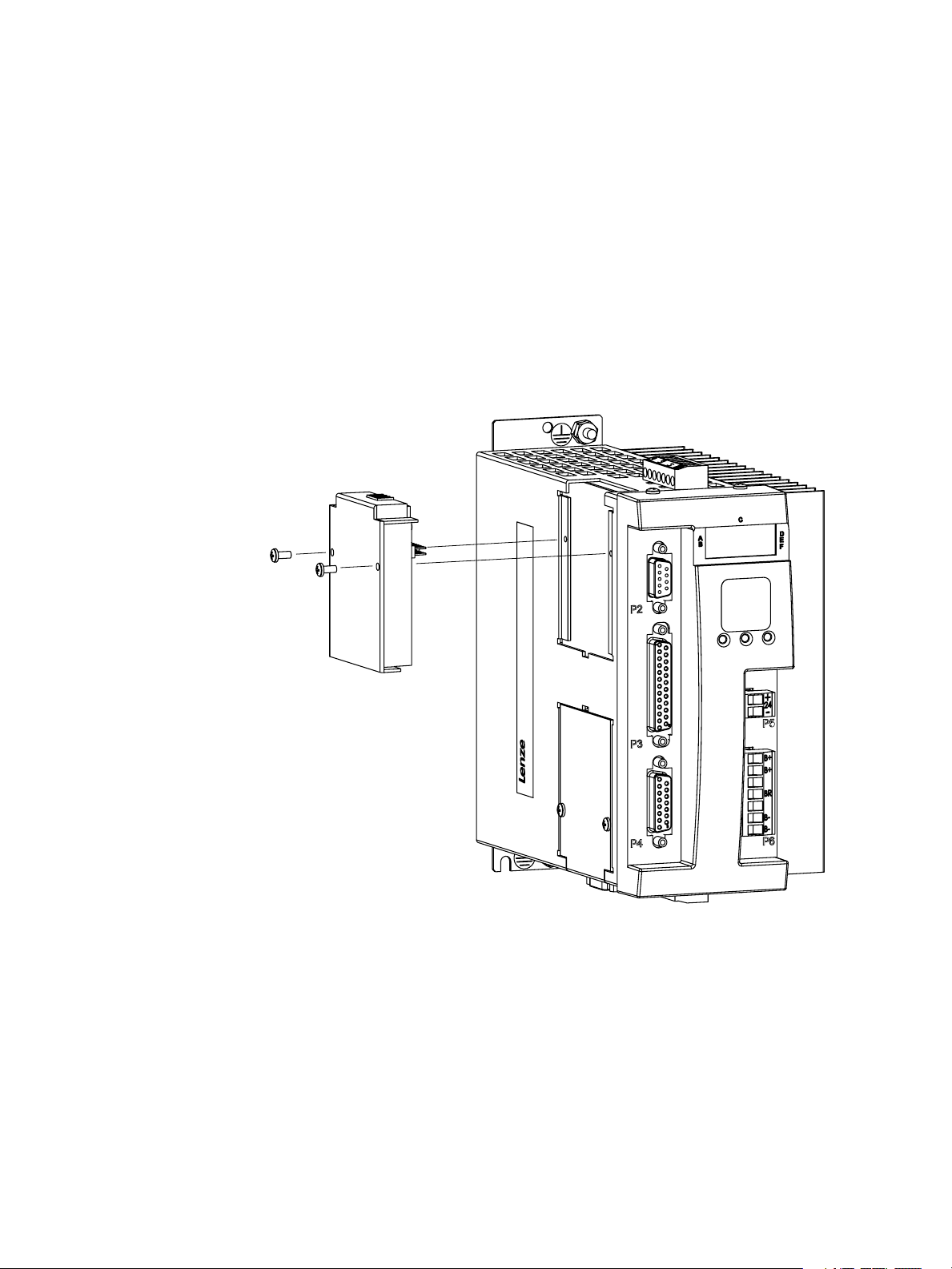
3.3 Installation
The E94ZCAN1 CANopen Communication Module is designed to operate with the E94S
SimpleServo drive. For proper installation……
• Remove power from the drive and allow unit to discharge
• Remove blank module cover from Option Bay 1
• Plug in the 20 pin connector into drive
• Plug in the CANopen module
• Use set screws to connect module to drive
ENGLISH
ENGLISH
3
3
Page 6

3.4 Configuration
Drive 94 supports CANopen communication protocol through its CANopen Communication
Module. Upon power up, the drives firmware detects the CAN Module and automatically
enables both the CANopen functionality as well as the CANopen configuration menu.
We can utilize SimpleServo LED display and push buttons to both configure the drive for the
CAN network, as well as check and set drive parameters. The “UP” (▲) and “DOWN” (▼)
buttons are used to navigate through the drives parameters.
Power up the drive and review the display.
rvn_ Drive is Enabled and in Run mode. Disable the drive by deactivating the Enable
input.
DiS_ Drive is Disabled and ready to be configured. Press the “ENTER” button
( ) to continue.
StAt Current drive status. From here you use the “UP” (▲) and “DOWN” (▼) buttons to
navigate through the drives parameters. Press the “DOWN” (▼) button to continue.
CAnd CAN delay menu. This is the delay in seconds after which a “start remote node”
message can be broadcast and its value is between 0 and 5 (seconds). Press
the “ENTER” button ( ) to view this number and use the “UP” (▲) and “DOWN”
(▼) buttons to change the delay setting. Set the delay back to “0” and press the
“ENTER” button ( ) to exit. Press the “DOWN” (▼) button to continue.
Technical Data
CAn0 CAN operational mode. This is where you define what mode you want the drive to
be in at power up. This parameter is R/W. To view the setting, press the “ENTER”
button ( ). Use the “UP” (▲) and “DOWN” (▼) buttons to change the setting.
Select setting “1” and press the “ENTER” button ( ) to store your setting and to
exit. Press the “DOWN” (▼) button to continue
___0 CAN starts in pre-operational state.
___1 CAN starts in operational mode.
___2 CAN starts in operational mode and is a “quasi master”, meaning that it
will send “start remote node” message (described in standard DS301)
after a delay specified in CAnd menu.
CAnS CAN network status value. This is a binary representation of the status of the
CAN network. This is read only parameter and you can have more than one
status active at one time. Press the “ENTER” button ( ) to view status. Press the
“ENTER” button ( ) to exit. Press the “DOWN” (▼) button to continue.
___1 Initialization Complete.
___2 CAN bit or frame error occurred.
___4 CAN “error passive” occurred.
___8 Receive queue overrun occurred.
__16 Transmit queue overrun occurred.
__32 Reserved
__64 Reserved
_128 CAN “bus off” error occurred
ENGLISH
ENGLISH
4
4
Page 7

Technical Data
CAnA CAN network address. This parameter is R/W and can be between 0 and 127. This
is the drives address on the CAN Network. Press the “ENTER” button ( ) to view
address setting. Use the “UP” (▲) and “DOWN” (▼) buttons to change the setting.
Press the “ENTER” button ( ) to store your setting and to exit. Press the “DOWN”
(▼) button to continue.
CAnb CAN network baud rate. This is R/W parameter. Use the “UP” (▲) and “DOWN”
(▼) buttons to change the setting. Select setting “500” and press the “ENTER”
button ( ) to store your setting and to exit. Press the “DOWN” (▼) button to
continue.
1000 1000Kb baud rate
_800 800Kb baud rate
_500 500Kb baud rate
_250 250Kb baud rate
_125 125Kb baud rate
__50 50Kb baud rate
__20 20Kb baud rate
__10 10Kb baud rate
Hx.xx Drive Hardware Revision (ex. H1.01). Read only press the “DOWN” (▼) button to
continue.
Fx.xx Drive Firmware Revision (Version F1.12 or greater required for CANOPEN
Network). Read only. Press the “DOWN” (▼) button to continue.
OPEr Drive Operating Mode. This is a R/W parameter. Use the “UP” (▲) and “DOWN”
(▼) buttons to change the setting. Select either CAnV (CANBUS Velocity Mode)
or CAnt (CANBUS Torque Mode). Press the “ENTER” button ( ) to store your
setting and to exit. Press the “DOWN” (▼) button to continue.
POS_ Position Mode
uEL_ Velocity Mode
torq Torque Mode
CAnu CANBUS Velocity Mode
CAnt CANBUS Torque Mode
t-uL Velocity Limited Torque Mode.
bAud E94 Drive Baud Rate. This Baud Rate is only for RS232/RS485 communications.
It doesn’t affect the CANBUS Network. This is R/W parameter. Use the “UP” (▲)
and “DOWN” (▼) buttons to change the setting. Select setting “38.4” and press the
“ENTER” button ( ) to store your setting and to exit. Press the “DOWN” (▼) button
to continue.
_38.4 8400 bits per second
_19.2 19200 bits per second
__9.6 9600 bits per second
ENGLISH
ENGLISH
5
5
Page 8

Technical Data
Adr_ E94 Drive address. This address is only for RS232/RS485 communications. It
doesn’t affect the CANBUS Network. This parameter is R/W and can be between 0
and 31. Press the “ENTER” button ( ) to view address setting. Use the “UP” (▲)
and “DOWN” (▼) buttons to change the setting. Press the “ENTER” button ( ) to
store your setting and to exit. Press the “DOWN” (▼) button to continue.
FLtS E94 Drive Fault History. This parameter is Read only. Press the “ENTER” button (
) to view. Use the “UP” (▲) and “DOWN” (▼) buttons to scroll through the fault
history. Press the “ENTER” button ( ) to exit. Press the “DOWN” (▼) button to
continue.
Ht__ E94 Drive Heatsink Temperature. This parameter is Read only and shows heatsink
temperature in °C if greater than 40°C. Otherwise the display show “LO” (low).
Press the “ENTER” button ( ) to view. Press the “ENTER” button ( ) again to
exit. Press the “DOWN” (▼) button to continue.
EnC_ E94 Drive Encoder Activity. This parameter is Read only and shows primary
encoder counts for encoder diagnostics activity. Press the “ENTER” button ( ) to
view. Press the “ENTER” button ( ) again to exit. Press the “DOWN” (▼) button
to continue.
HALL E94 Drive Hall Activity. This parameter is Read only and displays the motors Hall
sensor state. Press the “ENTER” button ( ) to view. Press the “ENTER” button (
) again to exit. Press the “DOWN” (▼) button to continue.
bUS_ E94 Drive DC Bus Voltage. This parameter is Read only and displays the DC bus
voltage value. Press the “ENTER” button ( ) to view. Press the “ENTER” button (
) again to exit. Press the “DOWN” (▼) button to continue.
CUrr E94 Drive Phase Current. This parameter is Read only and displays the current
value of the motors phase current (RMS) while the drive is enabled. If the drive is
disabled the display will show “diS”. Press the “ENTER” button ( ) to view. Press
the “ENTER” button ( ) again to exit. Press the “DOWN” (▼) button to continue.
ENGLISH
ENGLISH
6
6
Page 9

Communication Objects
4 CANopen DS301 Communication Profile Support
4.1 Supported NMT (Network Management) services:
The E94 Drive automatically goes to an Operational state upon reset without waiting for the
Start Node command from the NMT master.
• Start Node – Upon receiving this service request from the NMT master the drive will
resume operation. This only is applicable when the drive is in the Stopped state. The
drive resumes its move and its CANopen SDO and PDO services are operational again.
• Stop Node – Upon receiving this service request the drive stops its motion and holds its
position. (Note: power is still applied to the motor) The drive also disables its CANopen
SDO and PDO services.
• Reset Node – Upon receiving this service request the drive will reset. If the drive is in
motion it executes a quick stop before it resets.
• Reset Communication – Resets the CAN communication driver.
4.2 The Heartbeat Error Control Service
The E94 Drive can be set up as a heartbeat producer. In this mode the drive will periodically
send out a heartbeat requests. The heartbeat producer time is stored in index 0x1017 in the
object dictionary as a multiple of 1 millisecond.
Value of 0 for the heartbeat producer time disables the heartbeat service.
ENGLISH
7
Page 10

Communication Objects
4.3 Communication Objects
OBJECT NAME DESCRIPTION
1000h Device Type The E94 Drive is not DSP 402 compliant but follows some
of the major velocity and torque profiles recommendations.
Therefore it uses custom device profile value of
0x00022192.
1001h Error Register The following values are allowed:
0 – NO error
1 – over voltage
2 – feedback error
3 – over current
4 – over temperature
5 – external fault detection
6 – over speed
7 – position error excess
8 – bad motor data
1008h Manufacturer Device Name Drive 94 uses the ‘SS94’ device name
1009h Manufacturer Hardware Version It is 0x94xx where xx is the current version number
100Ah Manufacturer Software Version It is 0x94xx where xx is the current version number
1017h Producer Heartbeat Time See 1.2 above
1018h Identity Object Vendor ID – 0x00456765
Product Code - 0x0000005E
1400h 1st receive PDO Parameter
(Torque)
1401h 2nd receive PDO Parameter
(Velocity)
1600h 1st receive PDO Mapping (Torque) Only the following static mapping is supported:
1601h 2nd receive PDO Mapping (Velocity) Only the following static mapping is supported:
Asynchronous PDO with 255 transmission type used only
if the drive is in CAN Torque mode. The target torque
update is triggered immediately upon receiving of this
RPDO.
Sub index 01 contains the RPDO COB-ID and has R/W
access. The default value of this COB-ID is 0x200 + CAN
network node id/address.
Asynchronous PDO with 255 transmission type and used
only if the drive is in CAN Velocity mode. The target
velocity update is triggered immediately upon receiving of
this RPDO.
Sub index 01 contains the RPDO COB-ID and has R/W
access. The default value of this COB-ID is 0x300 + CAN
network node id/address.
Sub index 01 -> 6040h Control word
Sub index 02 -> 6071h Target Torque
NOTE: This object is used only in CAN Torque mode
Sub index 01 -> 6040h Control word
Sub index 02 -> 60FFh Target Velocity
NOTE: This object is used only in CAN Velocity mode
ENGLISH
8
Page 11

Communication Objects
OBJECT NAME DESCRIPTION
1800h 1st transmit PDO Parameter
(Torque)
1801h 2nd transmit PDO Parameter
(Velocity)
1A00h 1st transmit PDO Mapping (Torque) Only the following static mapping is supported:
1A01h 2nd transmit PDO Mapping
(Velocity)
Sub index 01 -> TPDO COB-ID with R/W access. The
default value of this COB-ID is 0x180 + CAN network node
id/address.
Sub index 02 -> TPDO Type. Asynchronous TPDO with
255 transmission type.
Sub index 03 -> Inhibit Time in ms with R/W access. The
TPDO cannot be transmitted before the time set in this
parameter elapses.
Value of 0 disables this functionality.
Sub index 03 -> Event Timer in ms with R/W access. The
TPDO will be sent when the time set in this parameter
elapses whether or not an occurrence of the event
associated with this TPDO is detected.
NOTE: This TPDO is used in CAN Torque Mode only.
Inhibit Time & Event Time cannot both be 0 at the same
time.
Sub index 01 -> TPDO COB-ID with R/W access. The
default value of this COB-ID is 0x180 + CAN network node
id/address.
Sub index 02 -> TPDO Type. Asynchronous TPDO with
255 transmission type.
Sub index 03 -> Inhibit Time in ms with R/W access. The
TPDO cannot be transmitted before the time set in this
parameter elapses.
Value of 0 disables this functionality.
Sub index 03 -> Event Timer in ms with R/W access. The
TPDO will be sent when the time set in this parameter
elapses whether or not an occurrence of the event
associated with this TPDO is detected.
NOTE: This TPDO is used in CAN Velocity Mode only.
Inhibit Time & Event Time cannot both be 0 at the same
time.
Sub index 01 -> 6041h Status word
Sub index 02 -> 6077h Torque Actual Value
NOTE: This object is used only in CAN Torque mode
Only the following static mapping is supported:
Sub index 01 -> 6041h Status word
Sub index 02 -> 606Ch Velocity Actual Value
NOTE: This object is used only in CAN Velocity mode
ENGLISH
9
Page 12

Drive Objects
5. Drive 94 Specific Objects and functionality
When using the CANopen protocol the E94 drive has two modes of operation.
• CAN Velocity Mode
• CAN Torque Mode.
5.1 CAN Velocity mode
The Velocity reference is provided internally through the Object 60FFh (Target Velocity)
statically mapped in RPDO2. Commands can be sent to the drive through the Object 6040h
(Control Word) also statically mapped in RPDO2.
Please see the Object 6040h (Control Word) description below for the available
commands.
The CANopen network master should use the RPDO2 service to provide Target Velocity
and Control Commands to the drive.
The E94 Drive uses TPDO2 to send to the master status information through the Object
6041h Status word and the current velocity value through the Object 606Ch Velocity
Actual Value. Please see the Object 6041h Status word description below for the
available status information.
The drive94V.eds file is provided for usage by the CANopen master when the drive is in
CAN Velocity mode.
5.2 CAN Torque mode
The Torque reference is provided internally through the Object 6071h (Target Torque)
statically mapped in RPDO1. Commands can be sent to the drive through the Object 6040h
(Control Word) also statically mapped in RPDO2.
Please see the Object 6040h (Control Word) description below for the available
commands.
The CANopen network master should use the RPDO1 service to provide Target Torque and
Control Commands to the drive.
Drive 94 uses TPDO1 to send to the master status information through the Object 6041h
Status word and the current velocity value through the Object 6077h Torque Actual
Value. Please see the Object 6041h Status word description below for the available status
information.
The drive94T.eds file is provided for usage by the CANOpen master when the drive is in
CAN Torque mode.
ENGLISH
10
Page 13

Drive Objects
5.3 E94 Drive specific objects
Please see the provided drive94T.eds and drive94V.eds files and the SimpleServo Model 94 Users
Manual for a more complete description of all SDO objects and for setup instructions.
OBJECT NAME TYPE
6040h Control Word WORD The drive can execute the following
commands:
2 – Quick Stop
3 – Enable Drive
4 – Disable Drive
5 – Fault Reset
6 - Continue
6041h Status Word WORD Two bytes status is provided with the
following meaning:
Bit 0 - RUN indication
Bit 1 - Velocity in speed window
Bit 3 - Drive at fault
Bit 5 - Zero velocity reached
Bit 8 - Under voltage
Bit 11 - Regen indication
Bit 13 - Current limit reached
6071h Target Torque Float This object provides the Torque
reference in Amperes (A) to the DSP.
NOTE: This object is used only in CAN
Torque mode
6077h Torque Actual Value Float This object represents the actual Torque
value in Amperes (A) retrieved from the
DSP.
NOTE: This object is used only in CAN
Torque mode
60FFh Target Velocity Float This object provides the Velocity
reference in RPM to the DSP.
NOTE: This object is used only in CAN
Velocity mode
606Ch Velocity Actual Value Float This object represents the actual
Velocity value in RPM retrieved from the
DSP.
NOTE: This object is used only in CAN
Velocity mode
ENGLISH
11
Page 14

OBJECT NAME TYPE
6402h TorqueConst Float
6403h VoltageConst Float
6404h Inductance Float
6405h Resistance Float
6406h MaxPhaseCurrent Float
6407h TerminalVoltage WORD
6408h RotorInertia Float
6409h MaxVelocity Float
640Ah HallCode WORD
640Bh NumberPoles WORD
640Ch Encoder WORD
640Dh CurrentLimit Float
640Eh PeakCurrentLimit Float
640Fh InvertAnalogInput BYTE
6410h CurrentAnalogInput Float
6411h VelocityAnalogInput Float
6412h AccDecFlag BYTE
6413h AccelLimit Float
6414h DecelLimit Float
6415h StepRevolution WORD
6416h StepInputType BYTE
6417h AnalogOutput BYTE
6418h CurrentScale Float
6419h VelocityScale Float
641Ah AnalogBand WORD
641Bh AnalogOffset WORD
641Ch ZeroSpeed WORD
641Dh SpeedWindow WORD
641Eh AtSpeed WORD
641Fh PosErr Float
6420h MaxErrTime WORD
6421h VelPGain WORD
6422h VelIGain WORD
6423h PosPGain WORD
6424h PosIGain Float
6425h DGain WORD
6426h VFFGain Float
6427h ILimit WORD
6428h FaultReset BYTE
6429h FeedbackLoss BYTE
642Ah In2Func BYTE
Drive Objects
ENGLISH
12
Page 15

OBJECT NAME TYPE
642Bh In2Polarity BYTE
642Ch InBounceDelay input1 WORD
642Dh InBounceDelay input2 WORD
642Eh OutFunc output1 BYTE
642Fh OutFunc output2 BYTE
6430h OutPolarity output1 BYTE
6431h OutPolarity output2 BYTE
6432h Eset UNSIGNED WORD
6433h FeedbackType UNSIGNED WORD
6434h PwmIndex UNSIGNED BYTE
6435h GearRatioTop UNSIGNED WORD
6436h GearRatioBottom UNSIGNED WORD
6437h ReferenceType UNSIGNED BYTE
6438h MotorTempSensorResistance UNSIGNED WORD
6439h MotorTempSensorEnable UNSIGNED BYTE
6440h RegenDutyCycle UNSIGNED WORD
6441h EncoderRepeatSource UNSIGNED BYTE
6442h TorqueVelocityLimit FLOAT
6443h SeGearRatioTop SIGNED WORD
6444h SeGearRatioBottom UNSIGNED WORD
6445h SeEnable UNSIGNED BYTE
6446h SeIGain FLOAT
6447h SePosErr UNSIGNED WORD
6448h SeMaxErrTime FLOAT
6449h VelocityRegWnd SIGNED WORD
6450h LowPeakCurrentLimit FLOAT
6451h CANOperationalState UNSIGNED BYTE
6452h CANStartNodeDelay UNSIGNED BYTE
Drive Objects
ENGLISH
13
Page 16

l
AC Technology Corporation
member of the Lenze Group
630 Douglas Street
Uxbridge, MA 01569
Telephone: (508) 278-9100
Facsimile: (508) 278-7873
Doc ID: S94CAN01A
 Loading...