

Page 1
Inverter
8400
Inverter Drives 8400 BaseLine C
_ _ _ _ _ _ _ _ _ _ _ _ _ _
E84AVBCxxxxx...
Reference manual EN
Ä.>ZVä
13295753
L
Page 2

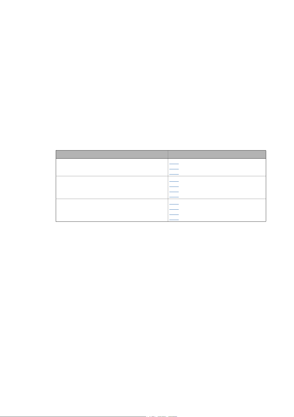
Overview of technical documentation for Inverter Drives 8400
_ _ _ _ _ _ _ _ _ _ _ _ _ _ _ _ _ _ _ _ _ _ _ _ _ _ _ _ _ _ _ _ _ _ _ _ _ _ _ _ _ _ _ _ _ _ _ _ _ _ _ _ _ _ _ _ _ _ _ _ _ _ _ _
Project planning, selection & ordering Legend:
Hardware manual 8400 BaseLine C/D Printed documentation
Catalogue Online documentation
(PDF/Engineer online help)
Mounting & wiring Abbreviations used:
MA 8400 BaseLine C BA Operating Instructions
MA for the accessories KHB Communication manual
MA Mounting instructions
Parameterisation SW Software/reference manual
SW 8400 BaseLine C This documentation
Drive commissioning
SW 8400 BaseLine C This documentation
Chapter "Commissioning"
Chapter "Diagnostics & error management"
Remote maintenance manual
Networking
KHB for the communication medium used
MA for the accessories
2 Lenze · 8400 BaseLine C · Reference manual · DMS 1.6 EN · 01/2014 · TD05
Page 3

Contents
Contents
_ _ _ _ _ _ _ _ _ _ _ _ _ _ _ _ _ _ _ _ _ _ _ _ _ _ _ _ _ _ _ _ _ _ _ _ _ _ _ _ _ _ _ _ _ _ _ _ _ _ _ _ _ _ _ _ _ _ _ _ _ _ _ _
1 About this documentation _ _ _ _ _ _ _ _ _ _ _ _ _ _ _ _ _ _ _ _ _ _ _ _ _ _ _ _ _ _ _ _ _ _ _ _ _ _ _ 8
1.1 Document history _ _ _ _ _ _ _ _ _ _ _ _ _ _ _ _ _ _ _ _ _ _ _ _ _ _ _ _ _ _ _ _ _ _ _ _ _ _ _ _ _ _ _ _ 8
1.2 Conventions used _ _ _ _ _ _ _ _ _ _ _ _ _ _ _ _ _ _ _ _ _ _ _ _ _ _ _ _ _ _ _ _ _ _ _ _ _ _ _ _ _ _ _ _ 9
1.3 Terminology used _ _ _ _ _ _ _ _ _ _ _ _ _ _ _ _ _ _ _ _ _ _ _ _ _ _ _ _ _ _ _ _ _ _ _ _ _ _ _ _ _ _ _ _ 10
1.4 Definition of the notes used _ _ _ _ _ _ _ _ _ _ _ _ _ _ _ _ _ _ _ _ _ _ _ _ _ _ _ _ _ _ _ _ _ _ _ _ _ _ 11
2 Introduction: Parameterising the controller _ _ _ _ _ _ _ _ _ _ _ _ _ _ _ _ _ _ _ _ _ _ _ _ _ _ _ _ _ _ 12
2.1 General notes on parameters _ _ _ _ _ _ _ _ _ _ _ _ _ _ _ _ _ _ _ _ _ _ _ _ _ _ _ _ _ _ _ _ _ _ _ _ _ _ 13
2.2 Handling the memory module _ _ _ _ _ _ _ _ _ _ _ _ _ _ _ _ _ _ _ _ _ _ _ _ _ _ _ _ _ _ _ _ _ _ _ _ _ 14
2.3 Internal Keypad _ _ _ _ _ _ _ _ _ _ _ _ _ _ _ _ _ _ _ _ _ _ _ _ _ _ _ _ _ _ _ _ _ _ _ _ _ _ _ _ _ _ _ _ _ 17
2.3.1 Display elements and control panel _ _ _ _ _ _ _ _ _ _ _ _ _ _ _ _ _ _ _ _ _ _ _ _ _ _ _ _ _ 17
2.3.2 LED status display _ _ _ _ _ _ _ _ _ _ _ _ _ _ _ _ _ _ _ _ _ _ _ _ _ _ _ _ _ _ _ _ _ _ _ _ _ _ 18
2.3.3 Display messages _ _ _ _ _ _ _ _ _ _ _ _ _ _ _ _ _ _ _ _ _ _ _ _ _ _ _ _ _ _ _ _ _ _ _ _ _ _ _ 19
2.3.4 Menu structure _ _ _ _ _ _ _ _ _ _ _ _ _ _ _ _ _ _ _ _ _ _ _ _ _ _ _ _ _ _ _ _ _ _ _ _ _ _ _ _ 21
2.3.5 User menu _ _ _ _ _ _ _ _ _ _ _ _ _ _ _ _ _ _ _ _ _ _ _ _ _ _ _ _ _ _ _ _ _ _ _ _ _ _ _ _ _ _ 22
2.3.6 Quick saving of all parameters at the push of a button _ _ _ _ _ _ _ _ _ _ _ _ _ _ _ _ _ _ 23
2.3.7 Password protection _ _ _ _ _ _ _ _ _ _ _ _ _ _ _ _ _ _ _ _ _ _ _ _ _ _ _ _ _ _ _ _ _ _ _ _ _ 23
3 Commissioning _ _ _ _ _ _ _ _ _ _ _ _ _ _ _ _ _ _ _ _ _ _ _ _ _ _ _ _ _ _ _ _ _ _ _ _ _ _ _ _ _ _ _ _ _ 25
3.1 Safety instructions with regard to commissioning _ _ _ _ _ _ _ _ _ _ _ _ _ _ _ _ _ _ _ _ _ _ _ _ _ _ 25
3.2 Preparing the 8400 BaseLine for commissioning _ _ _ _ _ _ _ _ _ _ _ _ _ _ _ _ _ _ _ _ _ _ _ _ _ _ _ 26
3.3 Commissioning with integrated keypad _ _ _ _ _ _ _ _ _ _ _ _ _ _ _ _ _ _ _ _ _ _ _ _ _ _ _ _ _ _ _ _ 27
3.3.1 Load Lenze setting _ _ _ _ _ _ _ _ _ _ _ _ _ _ _ _ _ _ _ _ _ _ _ _ _ _ _ _ _ _ _ _ _ _ _ _ _ _ 27
3.3.2 Parameterise drive/application _ _ _ _ _ _ _ _ _ _ _ _ _ _ _ _ _ _ _ _ _ _ _ _ _ _ _ _ _ _ _ 28
3.3.3 Save parameter settings safe against mains failure _ _ _ _ _ _ _ _ _ _ _ _ _ _ _ _ _ _ _ _ 29
3.3.4 Enable controller and select speed _ _ _ _ _ _ _ _ _ _ _ _ _ _ _ _ _ _ _ _ _ _ _ _ _ _ _ _ _ 30
3.4 Commissioning with the »Engineer« _ _ _ _ _ _ _ _ _ _ _ _ _ _ _ _ _ _ _ _ _ _ _ _ _ _ _ _ _ _ _ _ _ _ 31
3.4.1 Preconditions for commissioning with the »Engineer« _ _ _ _ _ _ _ _ _ _ _ _ _ _ _ _ _ _ 31
3.4.2 Creating an »Engineer« project & going online _ _ _ _ _ _ _ _ _ _ _ _ _ _ _ _ _ _ _ _ _ _ _ 32
3.4.3 Parameterise drive/application _ _ _ _ _ _ _ _ _ _ _ _ _ _ _ _ _ _ _ _ _ _ _ _ _ _ _ _ _ _ _ 33
3.4.4 Save parameter settings safe against mains failure _ _ _ _ _ _ _ _ _ _ _ _ _ _ _ _ _ _ _ _ 37
3.4.5 Enable controller and select speed _ _ _ _ _ _ _ _ _ _ _ _ _ _ _ _ _ _ _ _ _ _ _ _ _ _ _ _ _ 37
3.5 PC manual control _ _ _ _ _ _ _ _ _ _ _ _ _ _ _ _ _ _ _ _ _ _ _ _ _ _ _ _ _ _ _ _ _ _ _ _ _ _ _ _ _ _ _ _ 39
3.5.1 Activating PC manual control _ _ _ _ _ _ _ _ _ _ _ _ _ _ _ _ _ _ _ _ _ _ _ _ _ _ _ _ _ _ _ _ 39
3.5.2 Speed control _ _ _ _ _ _ _ _ _ _ _ _ _ _ _ _ _ _ _ _ _ _ _ _ _ _ _ _ _ _ _ _ _ _ _ _ _ _ _ _ _ 42
4 Device control (DCTRL) _ _ _ _ _ _ _ _ _ _ _ _ _ _ _ _ _ _ _ _ _ _ _ _ _ _ _ _ _ _ _ _ _ _ _ _ _ _ _ _ _ 44
4.1 Device commands _ _ _ _ _ _ _ _ _ _ _ _ _ _ _ _ _ _ _ _ _ _ _ _ _ _ _ _ _ _ _ _ _ _ _ _ _ _ _ _ _ _ _ _ 46
4.1.1 Load Lenze setting _ _ _ _ _ _ _ _ _ _ _ _ _ _ _ _ _ _ _ _ _ _ _ _ _ _ _ _ _ _ _ _ _ _ _ _ _ _ 48
4.1.2 Loading parameter settings _ _ _ _ _ _ _ _ _ _ _ _ _ _ _ _ _ _ _ _ _ _ _ _ _ _ _ _ _ _ _ _ _ 48
4.1.3 Save parameter settings _ _ _ _ _ _ _ _ _ _ _ _ _ _ _ _ _ _ _ _ _ _ _ _ _ _ _ _ _ _ _ _ _ _ _ 49
4.1.4 Import EPM data _ _ _ _ _ _ _ _ _ _ _ _ _ _ _ _ _ _ _ _ _ _ _ _ _ _ _ _ _ _ _ _ _ _ _ _ _ _ _ 50
4.1.5 Enable/Inhibit controller _ _ _ _ _ _ _ _ _ _ _ _ _ _ _ _ _ _ _ _ _ _ _ _ _ _ _ _ _ _ _ _ _ _ _ 50
4.1.6 Activate/Deactivate quick stop _ _ _ _ _ _ _ _ _ _ _ _ _ _ _ _ _ _ _ _ _ _ _ _ _ _ _ _ _ _ _ 50
4.1.7 Reset error _ _ _ _ _ _ _ _ _ _ _ _ _ _ _ _ _ _ _ _ _ _ _ _ _ _ _ _ _ _ _ _ _ _ _ _ _ _ _ _ _ _ 51
4.1.8 Delete logbook _ _ _ _ _ _ _ _ _ _ _ _ _ _ _ _ _ _ _ _ _ _ _ _ _ _ _ _ _ _ _ _ _ _ _ _ _ _ _ _ 51
4.1.9 Identify motor parameters _ _ _ _ _ _ _ _ _ _ _ _ _ _ _ _ _ _ _ _ _ _ _ _ _ _ _ _ _ _ _ _ _ _ 51
4.1.10 CAN reset node _ _ _ _ _ _ _ _ _ _ _ _ _ _ _ _ _ _ _ _ _ _ _ _ _ _ _ _ _ _ _ _ _ _ _ _ _ _ _ _ 52
4.2 Device states _ _ _ _ _ _ _ _ _ _ _ _ _ _ _ _ _ _ _ _ _ _ _ _ _ _ _ _ _ _ _ _ _ _ _ _ _ _ _ _ _ _ _ _ _ _ _ 53
4.2.1 Init _ _ _ _ _ _ _ _ _ _ _ _ _ _ _ _ _ _ _ _ _ _ _ _ _ _ _ _ _ _ _ _ _ _ _ _ _ _ _ _ _ _ _ _ _ _ _ 55
4.2.2 MotorIdent _ _ _ _ _ _ _ _ _ _ _ _ _ _ _ _ _ _ _ _ _ _ _ _ _ _ _ _ _ _ _ _ _ _ _ _ _ _ _ _ _ _ 56
4.2.3 SafeTorqueOff _ _ _ _ _ _ _ _ _ _ _ _ _ _ _ _ _ _ _ _ _ _ _ _ _ _ _ _ _ _ _ _ _ _ _ _ _ _ _ _ 56
4.2.4 ReadyToSwitchON _ _ _ _ _ _ _ _ _ _ _ _ _ _ _ _ _ _ _ _ _ _ _ _ _ _ _ _ _ _ _ _ _ _ _ _ _ _ 57
4.2.5 SwitchedON _ _ _ _ _ _ _ _ _ _ _ _ _ _ _ _ _ _ _ _ _ _ _ _ _ _ _ _ _ _ _ _ _ _ _ _ _ _ _ _ _ _ 58
4.2.6 OperationEnabled _ _ _ _ _ _ _ _ _ _ _ _ _ _ _ _ _ _ _ _ _ _ _ _ _ _ _ _ _ _ _ _ _ _ _ _ _ _ 59
Lenze · 8400 BaseLine C · Reference manual · DMS 1.6 EN · 01/2014 · TD05 3
Page 4

Contents
_ _ _ _ _ _ _ _ _ _ _ _ _ _ _ _ _ _ _ _ _ _ _ _ _ _ _ _ _ _ _ _ _ _ _ _ _ _ _ _ _ _ _ _ _ _ _ _ _ _ _ _ _ _ _ _ _ _ _ _ _ _ _ _
4.2.7 Trouble _ _ _ _ _ _ _ _ _ _ _ _ _ _ _ _ _ _ _ _ _ _ _ _ _ _ _ _ _ _ _ _ _ _ _ _ _ _ _ _ _ _ _ _ 60
4.2.8 Fault _ _ _ _ _ _ _ _ _ _ _ _ _ _ _ _ _ _ _ _ _ _ _ _ _ _ _ _ _ _ _ _ _ _ _ _ _ _ _ _ _ _ _ _ _ _ 61
4.3 "Inhibit at power-on" auto-start option _ _ _ _ _ _ _ _ _ _ _ _ _ _ _ _ _ _ _ _ _ _ _ _ _ _ _ _ _ _ _ _ 62
5 Motor control (MCTRL) _ _ _ _ _ _ _ _ _ _ _ _ _ _ _ _ _ _ _ _ _ _ _ _ _ _ _ _ _ _ _ _ _ _ _ _ _ _ _ _ _ 64
5.1 Motor selection/Motor data _ _ _ _ _ _ _ _ _ _ _ _ _ _ _ _ _ _ _ _ _ _ _ _ _ _ _ _ _ _ _ _ _ _ _ _ _ _ 65
5.1.1 Selecting a motor from the motor catalogue in the »Engineer« _ _ _ _ _ _ _ _ _ _ _ _ _ _ 68
5.1.2 Automatic motor data identification _ _ _ _ _ _ _ _ _ _ _ _ _ _ _ _ _ _ _ _ _ _ _ _ _ _ _ _ 70
5.2 Selecting the control mode _ _ _ _ _ _ _ _ _ _ _ _ _ _ _ _ _ _ _ _ _ _ _ _ _ _ _ _ _ _ _ _ _ _ _ _ _ _ _ 73
5.2.1 Selection help _ _ _ _ _ _ _ _ _ _ _ _ _ _ _ _ _ _ _ _ _ _ _ _ _ _ _ _ _ _ _ _ _ _ _ _ _ _ _ _ _ 75
5.3 Defining current and speed limits _ _ _ _ _ _ _ _ _ _ _ _ _ _ _ _ _ _ _ _ _ _ _ _ _ _ _ _ _ _ _ _ _ _ _ 76
5.4 V/f characteristic control (VFCplus) _ _ _ _ _ _ _ _ _ _ _ _ _ _ _ _ _ _ _ _ _ _ _ _ _ _ _ _ _ _ _ _ _ _ _ 78
5.4.1 Parameterisation dialog/signal flow _ _ _ _ _ _ _ _ _ _ _ _ _ _ _ _ _ _ _ _ _ _ _ _ _ _ _ _ 78
5.4.2 Basic settings _ _ _ _ _ _ _ _ _ _ _ _ _ _ _ _ _ _ _ _ _ _ _ _ _ _ _ _ _ _ _ _ _ _ _ _ _ _ _ _ _ 80
5.4.2.1 Defining the V/f characteristic shape _ _ _ _ _ _ _ _ _ _ _ _ _ _ _ _ _ _ _ _ _ 80
5.4.2.2 Defining current limits (Imax controller) _ _ _ _ _ _ _ _ _ _ _ _ _ _ _ _ _ _ _ 81
5.4.3 Optimise control behaviour _ _ _ _ _ _ _ _ _ _ _ _ _ _ _ _ _ _ _ _ _ _ _ _ _ _ _ _ _ _ _ _ _ 82
5.4.3.1 Adapting the V/f base frequency _ _ _ _ _ _ _ _ _ _ _ _ _ _ _ _ _ _ _ _ _ _ _ 83
5.4.3.2 Adapting the Vmin boost _ _ _ _ _ _ _ _ _ _ _ _ _ _ _ _ _ _ _ _ _ _ _ _ _ _ _ 84
5.4.3.3 Optimising the Imax controller _ _ _ _ _ _ _ _ _ _ _ _ _ _ _ _ _ _ _ _ _ _ _ _ 85
5.4.3.4 Torque limitation _ _ _ _ _ _ _ _ _ _ _ _ _ _ _ _ _ _ _ _ _ _ _ _ _ _ _ _ _ _ _ _ 85
5.4.4 Remedies for undesired drive behaviour _ _ _ _ _ _ _ _ _ _ _ _ _ _ _ _ _ _ _ _ _ _ _ _ _ _ 86
5.5 Sensorless vector control (SLVC) _ _ _ _ _ _ _ _ _ _ _ _ _ _ _ _ _ _ _ _ _ _ _ _ _ _ _ _ _ _ _ _ _ _ _ _ 87
5.5.1 Parameterisation dialog _ _ _ _ _ _ _ _ _ _ _ _ _ _ _ _ _ _ _ _ _ _ _ _ _ _ _ _ _ _ _ _ _ _ _ 88
5.5.2 Speed control with torque limitation _ _ _ _ _ _ _ _ _ _ _ _ _ _ _ _ _ _ _ _ _ _ _ _ _ _ _ _ 89
5.5.3 Basic settings _ _ _ _ _ _ _ _ _ _ _ _ _ _ _ _ _ _ _ _ _ _ _ _ _ _ _ _ _ _ _ _ _ _ _ _ _ _ _ _ _ 90
5.5.4 Optimise control behaviour _ _ _ _ _ _ _ _ _ _ _ _ _ _ _ _ _ _ _ _ _ _ _ _ _ _ _ _ _ _ _ _ _ 90
5.5.5 Remedies for undesired drive behaviour _ _ _ _ _ _ _ _ _ _ _ _ _ _ _ _ _ _ _ _ _ _ _ _ _ _ 91
5.6 Parameterisable additional functions _ _ _ _ _ _ _ _ _ _ _ _ _ _ _ _ _ _ _ _ _ _ _ _ _ _ _ _ _ _ _ _ _ 92
5.6.1 Selection of switching frequency _ _ _ _ _ _ _ _ _ _ _ _ _ _ _ _ _ _ _ _ _ _ _ _ _ _ _ _ _ _ 92
5.6.2 Flying restart function _ _ _ _ _ _ _ _ _ _ _ _ _ _ _ _ _ _ _ _ _ _ _ _ _ _ _ _ _ _ _ _ _ _ _ _ 94
5.6.3 DC-injection braking _ _ _ _ _ _ _ _ _ _ _ _ _ _ _ _ _ _ _ _ _ _ _ _ _ _ _ _ _ _ _ _ _ _ _ _ _ 96
5.6.4 Slip compensation _ _ _ _ _ _ _ _ _ _ _ _ _ _ _ _ _ _ _ _ _ _ _ _ _ _ _ _ _ _ _ _ _ _ _ _ _ _ 99
5.6.5 Oscillation damping _ _ _ _ _ _ _ _ _ _ _ _ _ _ _ _ _ _ _ _ _ _ _ _ _ _ _ _ _ _ _ _ _ _ _ _ _ 100
5.7 Braking operation/braking energy management _ _ _ _ _ _ _ _ _ _ _ _ _ _ _ _ _ _ _ _ _ _ _ _ _ _ _ 101
5.7.1 Setting the voltage source for braking operation _ _ _ _ _ _ _ _ _ _ _ _ _ _ _ _ _ _ _ _ _ _ 102
5.7.2 Avoiding thermal overload of the brake resistor _ _ _ _ _ _ _ _ _ _ _ _ _ _ _ _ _ _ _ _ _ _ 102
5.8 Monitoring _ _ _ _ _ _ _ _ _ _ _ _ _ _ _ _ _ _ _ _ _ _ _ _ _ _ _ _ _ _ _ _ _ _ _ _ _ _ _ _ _ _ _ _ _ _ _ _ 103
5.8.1 Device overload monitoring (Ixt) _ _ _ _ _ _ _ _ _ _ _ _ _ _ _ _ _ _ _ _ _ _ _ _ _ _ _ _ _ _ 103
5.8.2 Motor load monitoring (I2xt) _ _ _ _ _ _ _ _ _ _ _ _ _ _ _ _ _ _ _ _ _ _ _ _ _ _ _ _ _ _ _ _ 104
5.8.3 Brake resistor monitoring (I2xt) _ _ _ _ _ _ _ _ _ _ _ _ _ _ _ _ _ _ _ _ _ _ _ _ _ _ _ _ _ _ _ 106
5.8.4 Mains phase failure monitoring _ _ _ _ _ _ _ _ _ _ _ _ _ _ _ _ _ _ _ _ _ _ _ _ _ _ _ _ _ _ _ 107
5.5.4.1 Optimising the starting performance after a controller enable _ _ _ _ _ _ _ 90
5.6.3.1 Manual DC-injection braking (DCB) _ _ _ _ _ _ _ _ _ _ _ _ _ _ _ _ _ _ _ _ _ _ 97
5.6.3.2 Automatic DC-injection braking (Auto-DCB) _ _ _ _ _ _ _ _ _ _ _ _ _ _ _ _ _ 97
6I/O terminals _ _ _ _ _ _ _ _ _ _ _ _ _ _ _ _ _ _ _ _ _ _ _ _ _ _ _ _ _ _ _ _ _ _ _ _ _ _ _ _ _ _ _ _ _ _ _ 108
6.1 Digital terminals _ _ _ _ _ _ _ _ _ _ _ _ _ _ _ _ _ _ _ _ _ _ _ _ _ _ _ _ _ _ _ _ _ _ _ _ _ _ _ _ _ _ _ _ _ 109
6.2 Analog terminals _ _ _ _ _ _ _ _ _ _ _ _ _ _ _ _ _ _ _ _ _ _ _ _ _ _ _ _ _ _ _ _ _ _ _ _ _ _ _ _ _ _ _ _ 111
6.2.1 Parameterising analog input _ _ _ _ _ _ _ _ _ _ _ _ _ _ _ _ _ _ _ _ _ _ _ _ _ _ _ _ _ _ _ _ _ 112
6.3 User-defined terminal assignment _ _ _ _ _ _ _ _ _ _ _ _ _ _ _ _ _ _ _ _ _ _ _ _ _ _ _ _ _ _ _ _ _ _ _ 114
6.3.1 Source-destination principle _ _ _ _ _ _ _ _ _ _ _ _ _ _ _ _ _ _ _ _ _ _ _ _ _ _ _ _ _ _ _ _ _ 115
6.3.2 Changing the terminal assignment with the »Engineer« _ _ _ _ _ _ _ _ _ _ _ _ _ _ _ _ _ 116
6.3.3 Changing the terminal assignment via configuration parameters _ _ _ _ _ _ _ _ _ _ _ _ 117
6.4 Electrical data _ _ _ _ _ _ _ _ _ _ _ _ _ _ _ _ _ _ _ _ _ _ _ _ _ _ _ _ _ _ _ _ _ _ _ _ _ _ _ _ _ _ _ _ _ _ 119
4 Lenze · 8400 BaseLine C · Reference manual · DMS 1.6 EN · 01/2014 · TD05
Page 5

Contents
_ _ _ _ _ _ _ _ _ _ _ _ _ _ _ _ _ _ _ _ _ _ _ _ _ _ _ _ _ _ _ _ _ _ _ _ _ _ _ _ _ _ _ _ _ _ _ _ _ _ _ _ _ _ _ _ _ _ _ _ _ _ _ _
7 Drive application _ _ _ _ _ _ _ _ _ _ _ _ _ _ _ _ _ _ _ _ _ _ _ _ _ _ _ _ _ _ _ _ _ _ _ _ _ _ _ _ _ _ _ _ 121
7.1 Parameterisation dialog _ _ _ _ _ _ _ _ _ _ _ _ _ _ _ _ _ _ _ _ _ _ _ _ _ _ _ _ _ _ _ _ _ _ _ _ _ _ _ _ _ 122
7.1.1 Signal flow _ _ _ _ _ _ _ _ _ _ _ _ _ _ _ _ _ _ _ _ _ _ _ _ _ _ _ _ _ _ _ _ _ _ _ _ _ _ _ _ _ _ 124
7.1.1.1 Selection of the main speed setpoint _ _ _ _ _ _ _ _ _ _ _ _ _ _ _ _ _ _ _ _ _ 126
7.1.1.2 Motor potentiometer function _ _ _ _ _ _ _ _ _ _ _ _ _ _ _ _ _ _ _ _ _ _ _ _ 126
7.1.1.3 Process controller _ _ _ _ _ _ _ _ _ _ _ _ _ _ _ _ _ _ _ _ _ _ _ _ _ _ _ _ _ _ _ _ 126
7.2 Interface description _ _ _ _ _ _ _ _ _ _ _ _ _ _ _ _ _ _ _ _ _ _ _ _ _ _ _ _ _ _ _ _ _ _ _ _ _ _ _ _ _ _ 127
7.3 Setting parameters (short overview) _ _ _ _ _ _ _ _ _ _ _ _ _ _ _ _ _ _ _ _ _ _ _ _ _ _ _ _ _ _ _ _ _ _ 132
7.4 Pre-assignment of the drive application _ _ _ _ _ _ _ _ _ _ _ _ _ _ _ _ _ _ _ _ _ _ _ _ _ _ _ _ _ _ _ _ 133
7.4.1 Input connections _ _ _ _ _ _ _ _ _ _ _ _ _ _ _ _ _ _ _ _ _ _ _ _ _ _ _ _ _ _ _ _ _ _ _ _ _ _ 133
7.4.2 Output connections _ _ _ _ _ _ _ _ _ _ _ _ _ _ _ _ _ _ _ _ _ _ _ _ _ _ _ _ _ _ _ _ _ _ _ _ _ 134
7.4.3 Internal signal flow for control via terminals _ _ _ _ _ _ _ _ _ _ _ _ _ _ _ _ _ _ _ _ _ _ _ _ 135
7.4.4 Internal signal flow for control via CAN _ _ _ _ _ _ _ _ _ _ _ _ _ _ _ _ _ _ _ _ _ _ _ _ _ _ _ 136
7.4.5 Process data assignment for control via CAN _ _ _ _ _ _ _ _ _ _ _ _ _ _ _ _ _ _ _ _ _ _ _ _ 137
7.5 Terminal assignment of the control modes _ _ _ _ _ _ _ _ _ _ _ _ _ _ _ _ _ _ _ _ _ _ _ _ _ _ _ _ _ _ 139
7.5.1 Terminals 0 _ _ _ _ _ _ _ _ _ _ _ _ _ _ _ _ _ _ _ _ _ _ _ _ _ _ _ _ _ _ _ _ _ _ _ _ _ _ _ _ _ _ 140
7.5.2 Terminals 2 _ _ _ _ _ _ _ _ _ _ _ _ _ _ _ _ _ _ _ _ _ _ _ _ _ _ _ _ _ _ _ _ _ _ _ _ _ _ _ _ _ _ 140
7.5.3 Terminals 11 _ _ _ _ _ _ _ _ _ _ _ _ _ _ _ _ _ _ _ _ _ _ _ _ _ _ _ _ _ _ _ _ _ _ _ _ _ _ _ _ _ 141
7.5.4 Terminals 16 _ _ _ _ _ _ _ _ _ _ _ _ _ _ _ _ _ _ _ _ _ _ _ _ _ _ _ _ _ _ _ _ _ _ _ _ _ _ _ _ _ 141
7.5.5 Keypad _ _ _ _ _ _ _ _ _ _ _ _ _ _ _ _ _ _ _ _ _ _ _ _ _ _ _ _ _ _ _ _ _ _ _ _ _ _ _ _ _ _ _ _ 142
7.5.6 PC _ _ _ _ _ _ _ _ _ _ _ _ _ _ _ _ _ _ _ _ _ _ _ _ _ _ _ _ _ _ _ _ _ _ _ _ _ _ _ _ _ _ _ _ _ _ _ 143
7.5.7 CAN _ _ _ _ _ _ _ _ _ _ _ _ _ _ _ _ _ _ _ _ _ _ _ _ _ _ _ _ _ _ _ _ _ _ _ _ _ _ _ _ _ _ _ _ _ _ 144
8 Diagnostics & error management _ _ _ _ _ _ _ _ _ _ _ _ _ _ _ _ _ _ _ _ _ _ _ _ _ _ _ _ _ _ _ _ _ _ _ 145
8.1 Basics on error handling in the controller _ _ _ _ _ _ _ _ _ _ _ _ _ _ _ _ _ _ _ _ _ _ _ _ _ _ _ _ _ _ _ 145
8.2 Drive diagnostics with the »Engineer« _ _ _ _ _ _ _ _ _ _ _ _ _ _ _ _ _ _ _ _ _ _ _ _ _ _ _ _ _ _ _ _ _ 146
8.3 Drive diagnostics via bus system _ _ _ _ _ _ _ _ _ _ _ _ _ _ _ _ _ _ _ _ _ _ _ _ _ _ _ _ _ _ _ _ _ _ _ _ 148
8.4 Logbook _ _ _ _ _ _ _ _ _ _ _ _ _ _ _ _ _ _ _ _ _ _ _ _ _ _ _ _ _ _ _ _ _ _ _ _ _ _ _ _ _ _ _ _ _ _ _ _ _ 149
8.4.1 Functional description _ _ _ _ _ _ _ _ _ _ _ _ _ _ _ _ _ _ _ _ _ _ _ _ _ _ _ _ _ _ _ _ _ _ _ _ 149
8.4.2 Reading out logbook entries _ _ _ _ _ _ _ _ _ _ _ _ _ _ _ _ _ _ _ _ _ _ _ _ _ _ _ _ _ _ _ _ _ 150
8.4.3 Exporting logbook entries to a file _ _ _ _ _ _ _ _ _ _ _ _ _ _ _ _ _ _ _ _ _ _ _ _ _ _ _ _ _ _ 150
8.5 Monitoring _ _ _ _ _ _ _ _ _ _ _ _ _ _ _ _ _ _ _ _ _ _ _ _ _ _ _ _ _ _ _ _ _ _ _ _ _ _ _ _ _ _ _ _ _ _ _ _ 151
8.5.1 Monitoring configuration _ _ _ _ _ _ _ _ _ _ _ _ _ _ _ _ _ _ _ _ _ _ _ _ _ _ _ _ _ _ _ _ _ _ 152
8.5.2 Setting the error response _ _ _ _ _ _ _ _ _ _ _ _ _ _ _ _ _ _ _ _ _ _ _ _ _ _ _ _ _ _ _ _ _ _ 153
8.6 Maloperation of the drive _ _ _ _ _ _ _ _ _ _ _ _ _ _ _ _ _ _ _ _ _ _ _ _ _ _ _ _ _ _ _ _ _ _ _ _ _ _ _ _ 154
8.7 Error messages of the operating system _ _ _ _ _ _ _ _ _ _ _ _ _ _ _ _ _ _ _ _ _ _ _ _ _ _ _ _ _ _ _ _ 156
8.7.1 Structure of the error number (bit coding) _ _ _ _ _ _ _ _ _ _ _ _ _ _ _ _ _ _ _ _ _ _ _ _ _ 156
8.7.1.1 Error type _ _ _ _ _ _ _ _ _ _ _ _ _ _ _ _ _ _ _ _ _ _ _ _ _ _ _ _ _ _ _ _ _ _ _ _ 156
8.7.1.2 Error subject area _ _ _ _ _ _ _ _ _ _ _ _ _ _ _ _ _ _ _ _ _ _ _ _ _ _ _ _ _ _ _ _ 157
8.7.1.3 Error ID _ _ _ _ _ _ _ _ _ _ _ _ _ _ _ _ _ _ _ _ _ _ _ _ _ _ _ _ _ _ _ _ _ _ _ _ _ 157
8.7.1.4 Example for bit coding of the error number _ _ _ _ _ _ _ _ _ _ _ _ _ _ _ _ _ 158
8.7.2 Reset of error message _ _ _ _ _ _ _ _ _ _ _ _ _ _ _ _ _ _ _ _ _ _ _ _ _ _ _ _ _ _ _ _ _ _ _ _ 158
8.7.3 Short overview (A-Z) _ _ _ _ _ _ _ _ _ _ _ _ _ _ _ _ _ _ _ _ _ _ _ _ _ _ _ _ _ _ _ _ _ _ _ _ _ 159
8.7.4 Cause & possible remedies _ _ _ _ _ _ _ _ _ _ _ _ _ _ _ _ _ _ _ _ _ _ _ _ _ _ _ _ _ _ _ _ _ 161
Lenze · 8400 BaseLine C · Reference manual · DMS 1.6 EN · 01/2014 · TD05 5
Page 6

Contents
_ _ _ _ _ _ _ _ _ _ _ _ _ _ _ _ _ _ _ _ _ _ _ _ _ _ _ _ _ _ _ _ _ _ _ _ _ _ _ _ _ _ _ _ _ _ _ _ _ _ _ _ _ _ _ _ _ _ _ _ _ _ _ _
9 System bus "CAN on board" _ _ _ _ _ _ _ _ _ _ _ _ _ _ _ _ _ _ _ _ _ _ _ _ _ _ _ _ _ _ _ _ _ _ _ _ _ _ _ 169
9.1 General information _ _ _ _ _ _ _ _ _ _ _ _ _ _ _ _ _ _ _ _ _ _ _ _ _ _ _ _ _ _ _ _ _ _ _ _ _ _ _ _ _ _ _ 170
9.1.1 General data and application conditions _ _ _ _ _ _ _ _ _ _ _ _ _ _ _ _ _ _ _ _ _ _ _ _ _ _ 171
9.1.2 Supported protocols _ _ _ _ _ _ _ _ _ _ _ _ _ _ _ _ _ _ _ _ _ _ _ _ _ _ _ _ _ _ _ _ _ _ _ _ _ 171
9.1.3 Communication time _ _ _ _ _ _ _ _ _ _ _ _ _ _ _ _ _ _ _ _ _ _ _ _ _ _ _ _ _ _ _ _ _ _ _ _ _ 172
9.1.4 Activating the bus terminating resistor _ _ _ _ _ _ _ _ _ _ _ _ _ _ _ _ _ _ _ _ _ _ _ _ _ _ _ 173
9.1.5 Setting baud rate & node address _ _ _ _ _ _ _ _ _ _ _ _ _ _ _ _ _ _ _ _ _ _ _ _ _ _ _ _ _ _ 173
9.2 LED status displays for the system bus _ _ _ _ _ _ _ _ _ _ _ _ _ _ _ _ _ _ _ _ _ _ _ _ _ _ _ _ _ _ _ _ _ 174
9.3 Going online via system bus (CAN on board) _ _ _ _ _ _ _ _ _ _ _ _ _ _ _ _ _ _ _ _ _ _ _ _ _ _ _ _ _ 175
9.4 Structure of the CAN data telegram _ _ _ _ _ _ _ _ _ _ _ _ _ _ _ _ _ _ _ _ _ _ _ _ _ _ _ _ _ _ _ _ _ _ 176
9.4.1 Identifier _ _ _ _ _ _ _ _ _ _ _ _ _ _ _ _ _ _ _ _ _ _ _ _ _ _ _ _ _ _ _ _ _ _ _ _ _ _ _ _ _ _ _ 176
9.4.2 User data _ _ _ _ _ _ _ _ _ _ _ _ _ _ _ _ _ _ _ _ _ _ _ _ _ _ _ _ _ _ _ _ _ _ _ _ _ _ _ _ _ _ _ 178
9.5 Communication phases/network management _ _ _ _ _ _ _ _ _ _ _ _ _ _ _ _ _ _ _ _ _ _ _ _ _ _ _ _ 179
9.5.1 Status transitions _ _ _ _ _ _ _ _ _ _ _ _ _ _ _ _ _ _ _ _ _ _ _ _ _ _ _ _ _ _ _ _ _ _ _ _ _ _ _ 180
9.5.2 Network management telegram (NMT) _ _ _ _ _ _ _ _ _ _ _ _ _ _ _ _ _ _ _ _ _ _ _ _ _ _ _ 181
9.5.3 Parameterising the controller as CAN master _ _ _ _ _ _ _ _ _ _ _ _ _ _ _ _ _ _ _ _ _ _ _ _ 182
9.6 Process data transfer _ _ _ _ _ _ _ _ _ _ _ _ _ _ _ _ _ _ _ _ _ _ _ _ _ _ _ _ _ _ _ _ _ _ _ _ _ _ _ _ _ _ 183
9.6.1 Available process data objects _ _ _ _ _ _ _ _ _ _ _ _ _ _ _ _ _ _ _ _ _ _ _ _ _ _ _ _ _ _ _ _ 184
9.6.1.1 RPDO1 | Port block "LP_CanIn1" _ _ _ _ _ _ _ _ _ _ _ _ _ _ _ _ _ _ _ _ _ _ _ _ 185
9.6.1.2 RPDO2 | Port block "LP_CanIn2" _ _ _ _ _ _ _ _ _ _ _ _ _ _ _ _ _ _ _ _ _ _ _ _ 186
9.6.1.3 TPDO1 | Port block "LP_CanOut1" _ _ _ _ _ _ _ _ _ _ _ _ _ _ _ _ _ _ _ _ _ _ _ 187
9.6.1.4 TPDO2 | Port block "LP_CanOut2" _ _ _ _ _ _ _ _ _ _ _ _ _ _ _ _ _ _ _ _ _ _ _ 188
9.6.2 Identifiers of the process data objects _ _ _ _ _ _ _ _ _ _ _ _ _ _ _ _ _ _ _ _ _ _ _ _ _ _ _ _ 189
9.6.3 Transmission type _ _ _ _ _ _ _ _ _ _ _ _ _ _ _ _ _ _ _ _ _ _ _ _ _ _ _ _ _ _ _ _ _ _ _ _ _ _ 190
9.6.4 PDO synchronisation via sync telegram _ _ _ _ _ _ _ _ _ _ _ _ _ _ _ _ _ _ _ _ _ _ _ _ _ _ _ 192
9.6.5 Monitoring of the RPDOs for data reception _ _ _ _ _ _ _ _ _ _ _ _ _ _ _ _ _ _ _ _ _ _ _ _ 193
9.7 Parameter data transfer _ _ _ _ _ _ _ _ _ _ _ _ _ _ _ _ _ _ _ _ _ _ _ _ _ _ _ _ _ _ _ _ _ _ _ _ _ _ _ _ _ 194
9.7.1 Identifiers of the parameter data objects _ _ _ _ _ _ _ _ _ _ _ _ _ _ _ _ _ _ _ _ _ _ _ _ _ _ 195
9.7.2 User data _ _ _ _ _ _ _ _ _ _ _ _ _ _ _ _ _ _ _ _ _ _ _ _ _ _ _ _ _ _ _ _ _ _ _ _ _ _ _ _ _ _ _ 195
9.7.2.1 Command _ _ _ _ _ _ _ _ _ _ _ _ _ _ _ _ _ _ _ _ _ _ _ _ _ _ _ _ _ _ _ _ _ _ _ _ 196
9.7.2.2 Addressing by means of index and subindex _ _ _ _ _ _ _ _ _ _ _ _ _ _ _ _ _ 197
9.7.2.3 Data 1 ... Data 4 _ _ _ _ _ _ _ _ _ _ _ _ _ _ _ _ _ _ _ _ _ _ _ _ _ _ _ _ _ _ _ _ _ 198
9.7.2.4 Error messages _ _ _ _ _ _ _ _ _ _ _ _ _ _ _ _ _ _ _ _ _ _ _ _ _ _ _ _ _ _ _ _ _ 199
9.7.3 Parameter data telegram examples _ _ _ _ _ _ _ _ _ _ _ _ _ _ _ _ _ _ _ _ _ _ _ _ _ _ _ _ _ 201
9.7.3.1 Read parameters _ _ _ _ _ _ _ _ _ _ _ _ _ _ _ _ _ _ _ _ _ _ _ _ _ _ _ _ _ _ _ _ 201
9.7.3.2 Write parameters _ _ _ _ _ _ _ _ _ _ _ _ _ _ _ _ _ _ _ _ _ _ _ _ _ _ _ _ _ _ _ _ 202
9.7.3.3 Read block parameters _ _ _ _ _ _ _ _ _ _ _ _ _ _ _ _ _ _ _ _ _ _ _ _ _ _ _ _ _ 203
9.8 Monitoring _ _ _ _ _ _ _ _ _ _ _ _ _ _ _ _ _ _ _ _ _ _ _ _ _ _ _ _ _ _ _ _ _ _ _ _ _ _ _ _ _ _ _ _ _ _ _ _ 206
9.8.1 Integrated error detection _ _ _ _ _ _ _ _ _ _ _ _ _ _ _ _ _ _ _ _ _ _ _ _ _ _ _ _ _ _ _ _ _ _ 206
9.8.2 Heartbeat protocol _ _ _ _ _ _ _ _ _ _ _ _ _ _ _ _ _ _ _ _ _ _ _ _ _ _ _ _ _ _ _ _ _ _ _ _ _ _ 207
9.8.2.1 Telegram structure _ _ _ _ _ _ _ _ _ _ _ _ _ _ _ _ _ _ _ _ _ _ _ _ _ _ _ _ _ _ _ 207
9.8.2.2 Parameter setting _ _ _ _ _ _ _ _ _ _ _ _ _ _ _ _ _ _ _ _ _ _ _ _ _ _ _ _ _ _ _ 208
9.8.2.3 Commissioning example _ _ _ _ _ _ _ _ _ _ _ _ _ _ _ _ _ _ _ _ _ _ _ _ _ _ _ _ 209
9.8.3 Emergency telegram _ _ _ _ _ _ _ _ _ _ _ _ _ _ _ _ _ _ _ _ _ _ _ _ _ _ _ _ _ _ _ _ _ _ _ _ _ 210
9.9 Implemented CANopen objects _ _ _ _ _ _ _ _ _ _ _ _ _ _ _ _ _ _ _ _ _ _ _ _ _ _ _ _ _ _ _ _ _ _ _ _ _ 211
6 Lenze · 8400 BaseLine C · Reference manual · DMS 1.6 EN · 01/2014 · TD05
Page 7

Contents
_ _ _ _ _ _ _ _ _ _ _ _ _ _ _ _ _ _ _ _ _ _ _ _ _ _ _ _ _ _ _ _ _ _ _ _ _ _ _ _ _ _ _ _ _ _ _ _ _ _ _ _ _ _ _ _ _ _ _ _ _ _ _ _
10 Parameter reference _ _ _ _ _ _ _ _ _ _ _ _ _ _ _ _ _ _ _ _ _ _ _ _ _ _ _ _ _ _ _ _ _ _ _ _ _ _ _ _ _ _ _ 228
10.1 Structure of the parameter descriptions _ _ _ _ _ _ _ _ _ _ _ _ _ _ _ _ _ _ _ _ _ _ _ _ _ _ _ _ _ _ _ _ 229
10.1.1 Data type _ _ _ _ _ _ _ _ _ _ _ _ _ _ _ _ _ _ _ _ _ _ _ _ _ _ _ _ _ _ _ _ _ _ _ _ _ _ _ _ _ _ _ 230
10.1.2 Parameters with read-only access _ _ _ _ _ _ _ _ _ _ _ _ _ _ _ _ _ _ _ _ _ _ _ _ _ _ _ _ _ _ 230
10.1.3 Parameters with write access _ _ _ _ _ _ _ _ _ _ _ _ _ _ _ _ _ _ _ _ _ _ _ _ _ _ _ _ _ _ _ _ 231
10.1.3.1 Parameters with setting range _ _ _ _ _ _ _ _ _ _ _ _ _ _ _ _ _ _ _ _ _ _ _ _ 231
10.1.3.2 Parameters with selection list _ _ _ _ _ _ _ _ _ _ _ _ _ _ _ _ _ _ _ _ _ _ _ _ _ 231
10.1.3.3 Parameters with bit-coded setting _ _ _ _ _ _ _ _ _ _ _ _ _ _ _ _ _ _ _ _ _ _ 232
10.1.3.4 Parameters with subcodes _ _ _ _ _ _ _ _ _ _ _ _ _ _ _ _ _ _ _ _ _ _ _ _ _ _ _ 233
10.1.4 Parameter attributes _ _ _ _ _ _ _ _ _ _ _ _ _ _ _ _ _ _ _ _ _ _ _ _ _ _ _ _ _ _ _ _ _ _ _ _ _ 234
10.2 Parameter list _ _ _ _ _ _ _ _ _ _ _ _ _ _ _ _ _ _ _ _ _ _ _ _ _ _ _ _ _ _ _ _ _ _ _ _ _ _ _ _ _ _ _ _ _ _ 235
10.2.1 Selection lists for configuration parameters _ _ _ _ _ _ _ _ _ _ _ _ _ _ _ _ _ _ _ _ _ _ _ _ 298
10.2.1.1 Selection list - analog signals _ _ _ _ _ _ _ _ _ _ _ _ _ _ _ _ _ _ _ _ _ _ _ _ _ 298
10.2.1.2 Selection list - digital signals _ _ _ _ _ _ _ _ _ _ _ _ _ _ _ _ _ _ _ _ _ _ _ _ _ _ 299
10.3 Table of attributes _ _ _ _ _ _ _ _ _ _ _ _ _ _ _ _ _ _ _ _ _ _ _ _ _ _ _ _ _ _ _ _ _ _ _ _ _ _ _ _ _ _ _ _ 300
11 Function library _ _ _ _ _ _ _ _ _ _ _ _ _ _ _ _ _ _ _ _ _ _ _ _ _ _ _ _ _ _ _ _ _ _ _ _ _ _ _ _ _ _ _ _ _ 304
11.1 L_MPot_1 _ _ _ _ _ _ _ _ _ _ _ _ _ _ _ _ _ _ _ _ _ _ _ _ _ _ _ _ _ _ _ _ _ _ _ _ _ _ _ _ _ _ _ _ _ _ _ _ 305
11.1.1 Activate & control motor potentiometer _ _ _ _ _ _ _ _ _ _ _ _ _ _ _ _ _ _ _ _ _ _ _ _ _ _ 307
11.1.2 Deactivate motor potentiometer _ _ _ _ _ _ _ _ _ _ _ _ _ _ _ _ _ _ _ _ _ _ _ _ _ _ _ _ _ _ 308
11.2 L_NSet_1 _ _ _ _ _ _ _ _ _ _ _ _ _ _ _ _ _ _ _ _ _ _ _ _ _ _ _ _ _ _ _ _ _ _ _ _ _ _ _ _ _ _ _ _ _ _ _ _ _ 309
11.2.1 Main setpoint path _ _ _ _ _ _ _ _ _ _ _ _ _ _ _ _ _ _ _ _ _ _ _ _ _ _ _ _ _ _ _ _ _ _ _ _ _ _ 310
11.2.2 JOG setpoints _ _ _ _ _ _ _ _ _ _ _ _ _ _ _ _ _ _ _ _ _ _ _ _ _ _ _ _ _ _ _ _ _ _ _ _ _ _ _ _ _ 310
11.2.3 Setpoint inversion _ _ _ _ _ _ _ _ _ _ _ _ _ _ _ _ _ _ _ _ _ _ _ _ _ _ _ _ _ _ _ _ _ _ _ _ _ _ 311
11.2.4 Ramp function generator for the main setpoint _ _ _ _ _ _ _ _ _ _ _ _ _ _ _ _ _ _ _ _ _ _ 311
11.2.5 S-shaped ramp _ _ _ _ _ _ _ _ _ _ _ _ _ _ _ _ _ _ _ _ _ _ _ _ _ _ _ _ _ _ _ _ _ _ _ _ _ _ _ _ 311
11.3 L_PCTRL_1 _ _ _ _ _ _ _ _ _ _ _ _ _ _ _ _ _ _ _ _ _ _ _ _ _ _ _ _ _ _ _ _ _ _ _ _ _ _ _ _ _ _ _ _ _ _ _ _ 312
11.3.1 Control characteristic _ _ _ _ _ _ _ _ _ _ _ _ _ _ _ _ _ _ _ _ _ _ _ _ _ _ _ _ _ _ _ _ _ _ _ _ _ 315
11.3.2 Ramp function generator _ _ _ _ _ _ _ _ _ _ _ _ _ _ _ _ _ _ _ _ _ _ _ _ _ _ _ _ _ _ _ _ _ _ 316
11.3.3 Operating range of the PID process controller _ _ _ _ _ _ _ _ _ _ _ _ _ _ _ _ _ _ _ _ _ _ _ 316
11.3.4 Evaluation of the output signal _ _ _ _ _ _ _ _ _ _ _ _ _ _ _ _ _ _ _ _ _ _ _ _ _ _ _ _ _ _ _ 316
11.4 L_RLQ_1 _ _ _ _ _ _ _ _ _ _ _ _ _ _ _ _ _ _ _ _ _ _ _ _ _ _ _ _ _ _ _ _ _ _ _ _ _ _ _ _ _ _ _ _ _ _ _ _ _ 317
11.5 LS_AnalogInput _ _ _ _ _ _ _ _ _ _ _ _ _ _ _ _ _ _ _ _ _ _ _ _ _ _ _ _ _ _ _ _ _ _ _ _ _ _ _ _ _ _ _ _ _ 319
11.6 LS_DigitalInput _ _ _ _ _ _ _ _ _ _ _ _ _ _ _ _ _ _ _ _ _ _ _ _ _ _ _ _ _ _ _ _ _ _ _ _ _ _ _ _ _ _ _ _ _ 320
11.7 LS_DigitalOutput _ _ _ _ _ _ _ _ _ _ _ _ _ _ _ _ _ _ _ _ _ _ _ _ _ _ _ _ _ _ _ _ _ _ _ _ _ _ _ _ _ _ _ _ 321
11.8 LS_DisFree _ _ _ _ _ _ _ _ _ _ _ _ _ _ _ _ _ _ _ _ _ _ _ _ _ _ _ _ _ _ _ _ _ _ _ _ _ _ _ _ _ _ _ _ _ _ _ _ 322
11.9 LS_DisFree_a _ _ _ _ _ _ _ _ _ _ _ _ _ _ _ _ _ _ _ _ _ _ _ _ _ _ _ _ _ _ _ _ _ _ _ _ _ _ _ _ _ _ _ _ _ _ _ 323
11.10 LS_DisFree_b _ _ _ _ _ _ _ _ _ _ _ _ _ _ _ _ _ _ _ _ _ _ _ _ _ _ _ _ _ _ _ _ _ _ _ _ _ _ _ _ _ _ _ _ _ _ _ 324
11.11 LS_DriveInterface _ _ _ _ _ _ _ _ _ _ _ _ _ _ _ _ _ _ _ _ _ _ _ _ _ _ _ _ _ _ _ _ _ _ _ _ _ _ _ _ _ _ _ _ 325
11.12 LS_Keypad _ _ _ _ _ _ _ _ _ _ _ _ _ _ _ _ _ _ _ _ _ _ _ _ _ _ _ _ _ _ _ _ _ _ _ _ _ _ _ _ _ _ _ _ _ _ _ _ 328
11.13 LS_ParFix _ _ _ _ _ _ _ _ _ _ _ _ _ _ _ _ _ _ _ _ _ _ _ _ _ _ _ _ _ _ _ _ _ _ _ _ _ _ _ _ _ _ _ _ _ _ _ _ _ 329
11.14 LS_ParFree_a _ _ _ _ _ _ _ _ _ _ _ _ _ _ _ _ _ _ _ _ _ _ _ _ _ _ _ _ _ _ _ _ _ _ _ _ _ _ _ _ _ _ _ _ _ _ _ 330
11.15 LS_ParFree_b _ _ _ _ _ _ _ _ _ _ _ _ _ _ _ _ _ _ _ _ _ _ _ _ _ _ _ _ _ _ _ _ _ _ _ _ _ _ _ _ _ _ _ _ _ _ _ 331
11.16 LS_SetError_1 _ _ _ _ _ _ _ _ _ _ _ _ _ _ _ _ _ _ _ _ _ _ _ _ _ _ _ _ _ _ _ _ _ _ _ _ _ _ _ _ _ _ _ _ _ _ 332
Index _ _ _ _ _ _ _ _ _ _ _ _ _ _ _ _ _ _ _ _ _ _ _ _ _ _ _ _ _ _ _ _ _ _ _ _ _ _ _ _ _ _ _ _ _ _ _ _ _ _ _ 333
Your opinion is important to us _ _ _ _ _ _ _ _ _ _ _ _ _ _ _ _ _ _ _ _ _ _ _ _ _ _ _ _ _ _ _ _ _ _ _ _ _ 340
Lenze · 8400 BaseLine C · Reference manual · DMS 1.6 EN · 01/2014 · TD05 7
Page 8

1 About this documentation
1.1 Document history
_ _ _ _ _ _ _ _ _ _ _ _ _ _ _ _ _ _ _ _ _ _ _ _ _ _ _ _ _ _ _ _ _ _ _ _ _ _ _ _ _ _ _ _ _ _ _ _ _ _ _ _ _ _ _ _ _ _ _ _ _ _ _ _
1 About this documentation
Danger!
The controller is a source of danger which may lead to death or severe injury of persons.
To protect yourself and others against these dangers, observe the safety instructions before switching on the controller.
Please read the safety instructions in the mounting instructions and the hardware manual of the 8400 BaseLine C controller. Both documents are supplied with the controller.
This documentation contains information on the parameterisation of the 8400 BaseLine C controller using the integrated keypad and the L-force »Engineer«.
The information in this documentation is valid for the 8400 BaseLine C controller with the following
nameplate data:
Product series Type designation From software version
8400 BaseLine C E84AVBCxxxxxxxx 01.00
Depending on the software version of the controller and the version of the installed »Engineer«
software, the screenshots in this documentation may differ from the representation in the »Engineer«.
Tip!
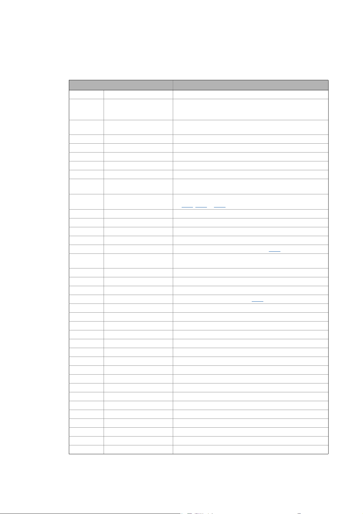
1.1 Document history
Version Description
Information and tools around the Lenze products can be found in the Download area on
http://www.Lenze.com
1.6 01/2014 TD05 Error corrections & supplements and converted to new layout
1.5 04/2013 TD05 Error corrections & supplements, parameter reference V03.04.00
1.4 04/2011 TD05 Error corrections & supplements, parameter reference V03.03.00
1.3 09/2010 TD05 Restructuring of some chapters, error corrections & supplements
1.2 11/2009 TD06 Error corrections
1.1 05/2009 TD06 Error corrections
1.0 04/2009 TD06 First edition
8
Lenze · 8400 BaseLine C · Reference manual · DMS 1.6 EN · 01/2014 · TD05
Page 9
1 About this documentation
1.2 Conventions used
_ _ _ _ _ _ _ _ _ _ _ _ _ _ _ _ _ _ _ _ _ _ _ _ _ _ _ _ _ _ _ _ _ _ _ _ _ _ _ _ _ _ _ _ _ _ _ _ _ _ _ _ _ _ _ _ _ _ _ _ _ _ _ _
1.2 Conventions used
This documentation uses the following conventions to distinguish between different types of information:
Type of information Writing Examples/notes
Spelling of numbers
Decimal separator Point The decimal point is generally used.
For example: 1234.56
Text
Version info Blue text colour All information that only applies to a certain controller
Program name » « The Lenze »Engineer« PC software ...
Window italics The Message window ... / The Options dialog box...
Variable identifier By setting bEnable to TRUE...
Control element bold The OK button... / The Copy command... / The Properties
Sequence of menu
commands
Shortcut <bold> Press <F1> to open the online help.
Hyperlink Underlined
DIP switch \
("Backslash")
Icons
Page reference ( 9) Optically highlighted reference to another page. In this
Step-by-step instructions
software version or higher is identified accordingly in this
documentation.
Example: This function extension is available from software
version V3.0!
tab... / The Name input field...
If the execution of a function requires several commands,
the individual commands are separated by an arrow: Select
Open to...
File
If a command requires a combination of keys, a "+" is placed
between the key symbols:
Use <Shift>+<ESC> to...
Optically highlighted reference to another topic. In this
documentation activated by mouse-click.
For separating the data of the DIP-Schalterbank from the
switch number, the Backlash" is used.
For instance, S2\8 indicates bank S2 and switch 8 (on the far
right).
documentation activated by mouse-click.
Step-by-step instructions are indicated by a pictograph.
Information that is only valid for or as from a certain software version of the controller are marked
accordingly in this documentation.
Lenze · 8400 BaseLine C · Reference manual · DMS 1.6 EN · 01/2014 · TD05 9
Page 10
1 About this documentation
1.3 Terminology used
_ _ _ _ _ _ _ _ _ _ _ _ _ _ _ _ _ _ _ _ _ _ _ _ _ _ _ _ _ _ _ _ _ _ _ _ _ _ _ _ _ _ _ _ _ _ _ _ _ _ _ _ _ _ _ _ _ _ _ _ _ _ _ _
1.3 Terminology used
Term Meaning
»Engineer« Lenze PC software which supports you in "engineering" (parameterisation, diag-
Application A technology application is a drive solution equipped with Lenze's experience
ASM Asynchronous motor
CINH Abbreviation: Controller inhibit (pulse inhibit)
Code Parameter used for controller parameterisation or monitoring. The term is usu-
DC-injection braking DC injection braking is to brake and/or hold the motor. For this purpose, the
DCTRL Abbreviation: Drive control (device control)
Display code Parameter that displays the current state or value of an input/output of a sys-
EPM Memory module on which all parametes of the drive system are saved non-vola-
Function block A function block can be compared with an integrated circuit that contains a cer-
Holding brake The holding brake serves to hold the rotor by means of a mechanical unit.
LA Abbreviation: Lenze Application block
Lenze setting This setting is the default factory setting of the device.
LP Abbreviation: Lenze Port block
LS Abbreviation: Lenze System block
MCTRL Abbreviation: Motor control
Port block Block for implementing the process data transfer via a fieldbus
QSP Quick stop ("Quick stop):
Service brake The service brake serves to shutdown rotary or translatory masses in motion in
SLVC Motor control: Sensorless vector control ("SensorLess Vector Control")
SM Synchronous motor
Subcode If a code contains several parameters, the individual parameters are stored un-
System block In the application, system blocks provide interfaces to basic functions and to the
nostics and configuration) throughout the whole life cycle, i.e. from planning to
maintenance of the commissioned machine.
and know-how in which function and system blocks interconnected to a signal
flow are the basis for implementing typical drive tasks.
ally called "index".
8400 BaseLine C creates a quasi DC field at the stator of the asynchronous machine. The energy to be dissipated is converted into heat in the rotor.
tem block.
tilely. These include the parameters of the controller and communication-relevant parameters for the communication unit used.
tain control logic and delivers one or several values when being executed.
• Each function block has a unique identifier, e.g. "L_MPot_1" (motor potentiometer function)
• Example: "LA_NCtrl" – block for the "actuating drive speed" application.
• Example: "LP_Network_In" – port block for fieldbus communication.
• Example: "LS_DigitalInput" – system block for digital input signals.
The motor control is decoupled from the setpoint selection and within a parameterisable deceleration time, the motor is brought to a standstill (n
a controlled manner. The energy to be dissipated in this process is converted into
heat in the form of friction energy. This process is a regular and recurring operating mode.
der "subcodes".
This manual uses a slash "/" as a separator between code and subcode
(e.g. "C118/3").
The term is usually called "subindex".
hardware of the controller (e.g. to the digital inputs).
act
=0).
10
Lenze · 8400 BaseLine C · Reference manual · DMS 1.6 EN · 01/2014 · TD05
Page 11

1 About this documentation
1.4 Definition of the notes used
_ _ _ _ _ _ _ _ _ _ _ _ _ _ _ _ _ _ _ _ _ _ _ _ _ _ _ _ _ _ _ _ _ _ _ _ _ _ _ _ _ _ _ _ _ _ _ _ _ _ _ _ _ _ _ _ _ _ _ _ _ _ _ _
Term Meaning
USB diagnostic adapter The USB diagnostic adapter is used for the operation, parameterisation, and di-
VFCplus Motor control: V/f characteristic control ("Voltage Frequency Control")
1.4 Definition of the notes used
The following signal words and symbols are used in this documentation to indicate dangers and important information:
Safety instructions
Layout of the safety instructions:
agnostics of the controller. Data are exchanged between the PC (USB connection) and the controller (diagnostic interface on the front) via the diagnostic
adapter.
• Order designation: E94AZCUS
Pictograph and signal word!
(characterise the type and severity of danger)
Note
(describes the danger and informs how to prevent dangerous situations)
Pictograph Signal word Meaning
Danger! Danger of personal injury through dangerous electrical voltage
Danger! Danger of personal injury through a general source of danger
Stop! Danger of property damage
Application notes
Pictograph Signal word Meaning
Note! Important note to ensure trouble-free operation
Refere nce to an i mmin ent d ange r tha t may resu lt in deat h or serio us pe rsonal in jury
if the corresponding measures are not taken.
Refere nce to an i mmin ent d ange r tha t may resu lt in deat h or serio us pe rsonal in jury
if the corresponding measures are not taken.
Reference to a possible danger that may result in property damage if the corresponding measures are not taken.
Tip! Useful tip for easy handling
Lenze · 8400 BaseLine C · Reference manual · DMS 1.6 EN · 01/2014 · TD05 11
Page 12
2 Introduction: Parameterising the controller
_ _ _ _ _ _ _ _ _ _ _ _ _ _ _ _ _ _ _ _ _ _ _ _ _ _ _ _ _ _ _ _ _ _ _ _ _ _ _ _ _ _ _ _ _ _ _ _ _ _ _ _ _ _ _ _ _ _ _ _ _ _ _ _
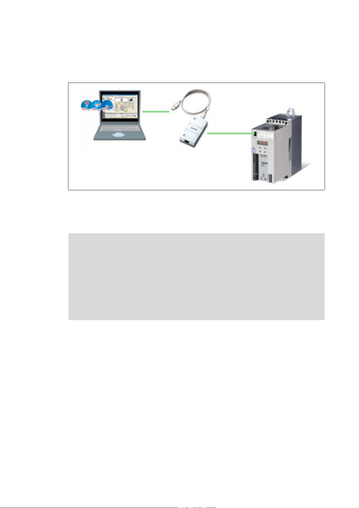
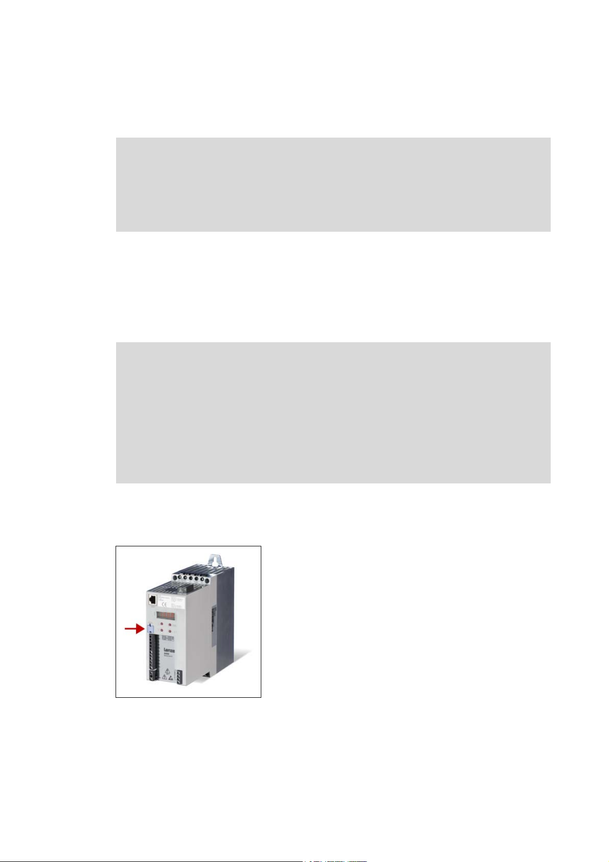
2 Introduction: Parameterising the controller
[2-1] Example configuration for parameterising the controller (here: BaseLine D)
Being a component of a machine which includes a speed-variable drive system, the controller needs
to be adjusted to its drive task and the motor. The controller is adjusted by changing parameters
which are saved in the memory module.
Danger!
The parameters can optionally be accessed from the integrated keypad, or the L-force »Engineer«,
or a master control via fieldbus communication:
In general, changing a parameter causes an immediate response in the controller!
• This may lead to undesirable behaviour on the motor shaft if the controller has been
enabled!
• Setpoint sources, for instance, may switch over all of a sudden (e.g. when configuring
the signal source for the main setpoint).
Certain device commands or settings which may cause critical states of drive behaviour
constitute exceptions. Such parameter changes are only possible if the controller is inhibited. Otherwise, a corresponding error message will be issued.
• The USB diagnostic adapter, for instance, can be used for the communication between the PC
(including the L-force »Engineer« software) and the controller, see illustration. The USB diagnostic adapter is the connection between the PC (free USB port) and the controller (diagnostic
interface).
• For fieldbus communication, the 8400 BaseLine C controller is provided with a CANopen interface.
12 Lenze · 8400 BaseLine C · Reference manual · DMS 1.6 EN · 01/2014 · TD05
Page 13
2 Introduction: Parameterising the controller
2.1 General notes on parameters
_ _ _ _ _ _ _ _ _ _ _ _ _ _ _ _ _ _ _ _ _ _ _ _ _ _ _ _ _ _ _ _ _ _ _ _ _ _ _ _ _ _ _ _ _ _ _ _ _ _ _ _ _ _ _ _ _ _ _ _ _ _ _ _
2.1 General notes on parameters
All parameters for controller parameterising or monitoring are saved as so-called "codes".
• The codes are numbered and designated by a "C" in front of the code, e.g. "C002" in the documentation and the keypad display.
• In addition, every code has a name and specific attributes:
• Access type (read, write)
•Data type
• Limit values
• Lenze setting (factory-set scaling)
• For the sake of clarity, some codes contain "subcodes" for saving parameters.
• This manual uses a slash "/" as a separator between code and subcode (e.g. "C115/1").
• In the keypad display, the subcodes are designated by a small "c", e.g. "c001".
• According to their functionality, the parameters are divided into three groups:
Parameter group Examples
Setting parameters
Parameters for specifying setpoints and for setting device /
monitoring functions.
Configuration parameters
Parameters for configuring signal connections within the device, e.g. assignment of the digital input terminals to the
control inputs of the application.
Diagnostic/Display parameters
Parameters for displaying device-internal process factors,
current actual values, and status messages, e.g. for diagnostic purposes. These are read-only parameters.
C007: Selection of control mode
C012
: Acceleration time - main setpoint
C039
: Fixed setpoints
C620
: System connection list: 16-bit
C621
: System connection list: Bool
C700
: LA_NCtrl: Analog connection list
C701
: LA_NCtrl: Digital connection list
C052
: Motor voltage
C137
: Device status
C150
: Status word
C165
: Error info
Tip!
The terms "code" and "subcode" generally correspond to the terms "index" and "subindex"
and "parameter" and "subparameter".
Lenze · 8400 BaseLine C · Reference manual · DMS 1.6 EN · 01/2014 · TD05 13
Page 14
2 Introduction: Parameterising the controller
2.2 Handling the memory module
_ _ _ _ _ _ _ _ _ _ _ _ _ _ _ _ _ _ _ _ _ _ _ _ _ _ _ _ _ _ _ _ _ _ _ _ _ _ _ _ _ _ _ _ _ _ _ _ _ _ _ _ _ _ _ _ _ _ _ _ _ _ _ _
2.2 Handling the memory module
Danger!
After power-off, wait at least three minutes before working on the controller. When removing the memory module, ensure that the controller is deenergised.
If the memory module has been removed and the device is switched on, the connector
pins are live and thus dangerous since the protection against contact is missing.
All parameters of the drive system are saved non-volatilely in the memory module of the controller.
This includes the parameters of the controller and parameters relevant for communication.
The plug-in version is especially suited for
• restoring an application after replacing a device.
• duplicating identical drive tasks within the 8400 BaseLine frequency inverter series, e.g. by
using the optionally available EPM Programmer.
Note!
• When the device is switched on, all parameters are automatically loaded from the memory module to the main memory of the controller.
• The 8400 BaseLine and 8400 motec controllers use the same (grey) memory module.
The memory module can be shifted between these controllers but the controller must
When handling the memory module, a distinction is drawn between the following scenarios:
Delivery status
be reparameterised afterwards.
• The memory module is not compatible with the memory modules of the
8400 StateLine and 8400 HighLine controllers.
• If the memory module has been removed, the "PS01" error message appears.
• The memory module is plugged into the EPM slot at the
front of the controller.
• The Lenze setting of the parameters is stored in the memory module.
• The memory module can be preconfigured with customerspecific data.
• The memory module is available as a spare part - without
any data.
14
Lenze · 8400 BaseLine C · Reference manual · DMS 1.6 EN · 01/2014 · TD05
Page 15

2 Introduction: Parameterising the controller
2.2 Handling the memory module
_ _ _ _ _ _ _ _ _ _ _ _ _ _ _ _ _ _ _ _ _ _ _ _ _ _ _ _ _ _ _ _ _ _ _ _ _ _ _ _ _ _ _ _ _ _ _ _ _ _ _ _ _ _ _ _ _ _ _ _ _ _ _ _
During operation
Stop!
The memory module must not be plugged in or unplugged during operation.
• The memory module (EPM) is required for operation.
• Full functionality of the memory module is even provided if the power supply has been switched
off and only the electronic components of the controller are externally supplied by a 24 V DC voltage, e.g. via the X4/24E terminal.
• Parameter settings can be saved manually.
• Parameter settings can be loaded manually.
• Parameter changes can be saved automatically.
Replacing the controller
• In the event of a device replacement, the entire parameter data of an axis can be copied to the
replacement device by "taking along" the memory module, so that additional PC or diagnosis
terminal operations are not required.
• When replacing the controller, the versions of the old device and the new device are of importance. Before data are actually transferred, the versions are internally checked. Basically, the following applies:
• Parameter sets of old devices with V 1.0 can be processed on new devices ≥ V1.0
(downward compatibility).
• Parameters of devices with higher versions are not supported on devices with lower versions.
An error message (PS02/PS03) occurs if the parameter set versions of the two devices are not
compatible.
Saving the parameters in the memory module safe against mains failure
Controller parameter changes via the »Engineer«, the integrated keypad, or a master control via
fieldbus communication will be lost after mains switching of the controller unless the settings have
been explicitly saved.
You have various opportunities to prevent a data loss by saving the parameter settings in the memory module:
• Quick saving of all parameters at the push of a button
• Automatic saving of parameter changes
• Manual saving of parameter settings
( 49)
( 49)
( 23)
Lenze · 8400 BaseLine C · Reference manual · DMS 1.6 EN · 01/2014 · TD05 15
Page 16

2 Introduction: Parameterising the controller
2.2 Handling the memory module
_ _ _ _ _ _ _ _ _ _ _ _ _ _ _ _ _ _ _ _ _ _ _ _ _ _ _ _ _ _ _ _ _ _ _ _ _ _ _ _ _ _ _ _ _ _ _ _ _ _ _ _ _ _ _ _ _ _ _ _ _ _ _ _
Parameter set transfer using the »Engineer«
When an online connection to the controller has been established, the following transfer functions
can directly be executed via the Toolbar or the Online menu using the L-force »Engineer«:
Symbol Menu command Shortcut
Download parameter set <F5>
Read parameter set from device <F7>
Save parameter set
Tip!
Detailed information on parameter set transfers using the »Engineer« can be found in the
»Engineer« online help.
16
Lenze · 8400 BaseLine C · Reference manual · DMS 1.6 EN · 01/2014 · TD05
Page 17
2 Introduction: Parameterising the controller
8888
B
ESC
C
D
E
F
A
1
2.3 Internal Keypad
_ _ _ _ _ _ _ _ _ _ _ _ _ _ _ _ _ _ _ _ _ _ _ _ _ _ _ _ _ _ _ _ _ _ _ _ _ _ _ _ _ _ _ _ _ _ _ _ _ _ _ _ _ _ _ _ _ _ _ _ _ _ _ _
2.3 Internal Keypad
The controller front is provided with an integrated keypad. Use the keypad for quick and simple parameter setting and for displaying current actual values and device states via the respective display
parameters.
Note!
After switching on the controller, the internal keypad performs a quick self-test. All segments of the display flash. After the self-test, the keypad shows "rdy" for a short time
and then changes to the display of the setpoint speed of the motor. The keypad is now
ready for operation.
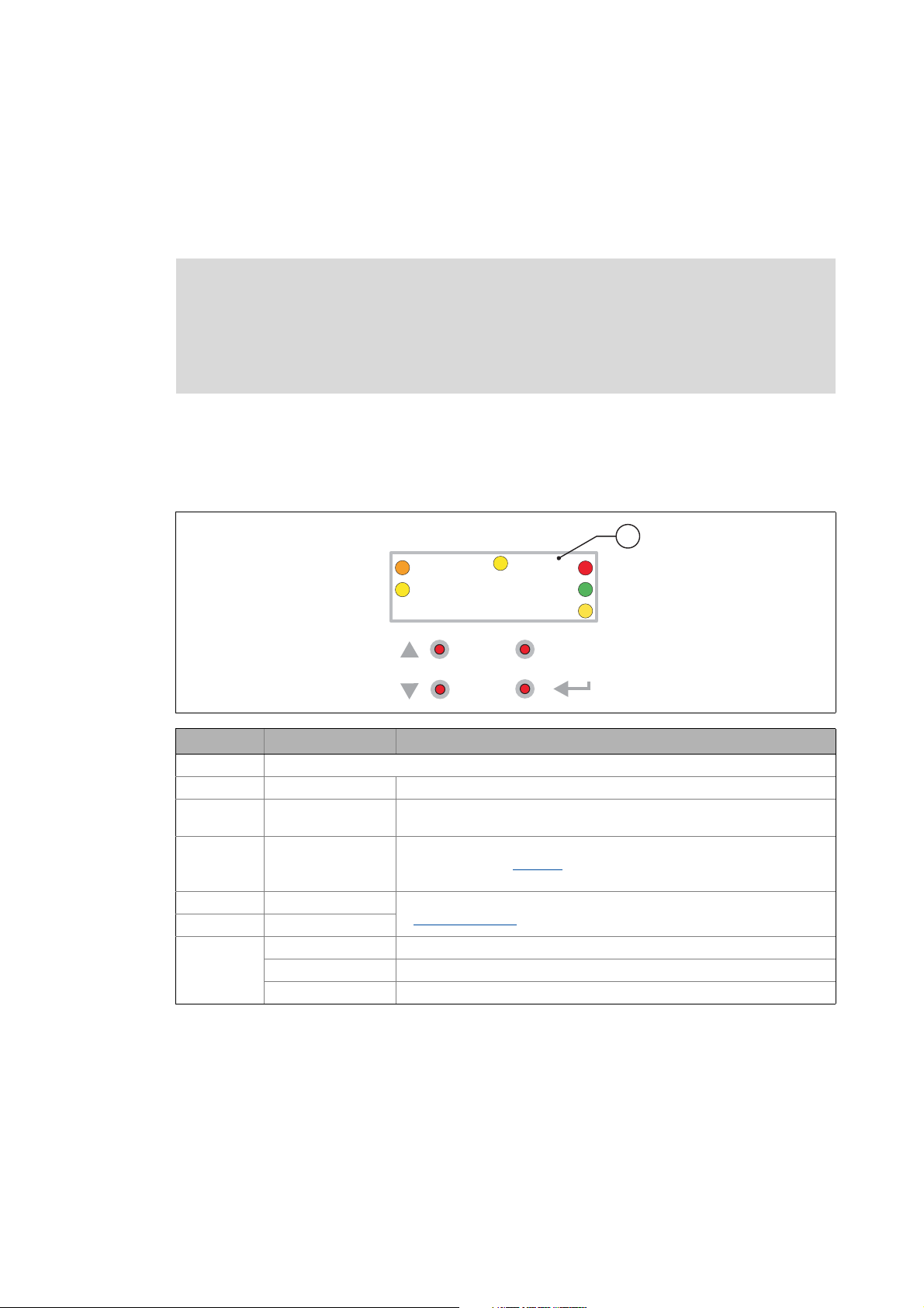
2.3.1 Display elements and control panel
Important status information of the controller is displayed optically by LEDs. The positions of the coloured LEDs are marked on the housing by letters.
Symbol Information Meaning
4-character display with LEDs (A ... F)
A orange Set current/torque limit is reached
B yellow Minus sign for identifying the negative numbers bigger than 4 characters
C yellow User LED
D red DRIVE ERROR / DRIVE READY
E green
F yellow Direction of rotation: CCW rotation
Off Direction of rotation: CW rotation
blinking Commanded direction is not equal to actual direction (e.g. during reversing)
when the rotational direction has been reversed.
•configurable via C621/42
• user-defined LED status
LED status display
( 18)
Lenze · 8400 BaseLine C · Reference manual · DMS 1.6 EN · 01/2014 · TD05 17
Page 18
2 Introduction: Parameterising the controller
8888
B
C
D
E
F
A
2.3 Internal Keypad
_ _ _ _ _ _ _ _ _ _ _ _ _ _ _ _ _ _ _ _ _ _ _ _ _ _ _ _ _ _ _ _ _ _ _ _ _ _ _ _ _ _ _ _ _ _ _ _ _ _ _ _ _ _ _ _ _ _ _ _ _ _ _ _
Control elements
Key Name Function
ESC Escape key On menu and parameter level: Back
In case of parameter processing: Abort (discard changed setting)
↵ Enter key On menu and parameter level: Next (confirm selection)
In case of parameter processing: OK (accept changed setting)
Long pressing (3 seconds): Saving of all parameters
Navigation key
upwards
Navigation key
downwards
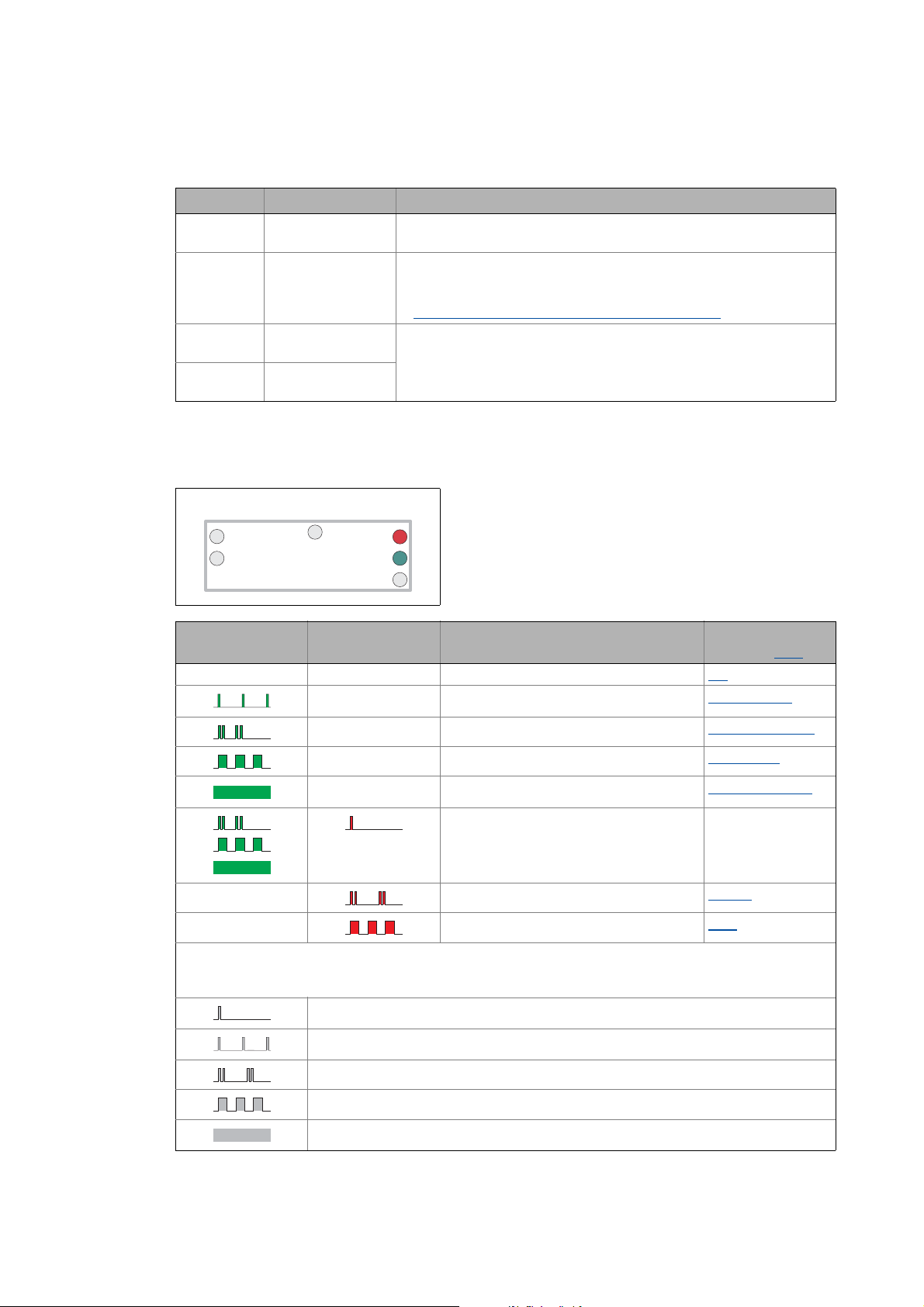
2.3.2 LED status display
Quick saving of all parameters at the push of a button
On menu and parameter level: Navigation
In case of parameter processing: Set parameter value
Long pressing (> 2 seconds): Quick scroll function
( 23)
Information on some operating states can quickly be obtained via the front D and E LEDs:
The meaning can be seen from the table below.
E
"DRIVE READY"
OFF OFF OFF or initialisation active Init
OFF Trouble is active Trouble
OFF Fault is active Fault
D
"DRIVE ERROR"
OFF Safe torque off is active SafeTorqueOff
OFF Device is ready to start ReadyToSwitchON
OFF Device is switched on SwitchedON
OFF Motor data identification/operation OperationEnabled
Description Device state
(Display in C137
The controller is ready to switch on, switched
on or the operation is enabled and a warning
is indicated.
)
18
Legend
The symbols used for indicating the LED states have the following meaning:
LED is flashing once approx. every 3 seconds (slow flash)
LED is flashing once approx. every 1.25 seconds (flash)
LED is flashing twice approx. every 1.25 seconds (double flash)
LED is blinking every second
LED is permanently on
Lenze · 8400 BaseLine C · Reference manual · DMS 1.6 EN · 01/2014 · TD05
Page 19
2 Introduction: Parameterising the controller
2.3 Internal Keypad
_ _ _ _ _ _ _ _ _ _ _ _ _ _ _ _ _ _ _ _ _ _ _ _ _ _ _ _ _ _ _ _ _ _ _ _ _ _ _ _ _ _ _ _ _ _ _ _ _ _ _ _ _ _ _ _ _ _ _ _ _ _ _ _
2.3.3 Display messages
Display Meaning
An01 constant Analog input 1: Current < 4 mA
bF blinking Identification error.
• Drive ID stored in EMP does not match the drive ID stored in the
controller.
br flashes during the hold time
of DC braking
CA06 constant CAN CRC error
CA07 constant CAN Bus Warn
CA08 constant CAN Bus Stopped
CA0b constant CAN Bus Live Time
CA0F constant CAN: Bit 14 ("SetFail") in the control word is set.
CAL blinking Identification is executed.
CAL / Err alternatively blinking Identification is not ready to start.
CAL / Stop alternatively blinking Identification is ready to start.
CE1 constant CAN: Time monitoring for RPDO1 has tripped.
CE2 constant CAN: Time monitoring for RPDO2 has tripped.
CE4 constant CAN Bus Off
CL constant Clamp: The current limit value selected in C022
dec constant Deceleration is temporarily suspended because of higher bus volta-
dF01 ... dF10 constant Internal error
dH69 constant Adjustment data error
Err blinking A wrong password has been entered.
FCL constant The current limit value selected in C022
FSt constant "Flying restart" function is executed.
ID1 constant Motor data identification error
LU constant DC bus undervoltage
OC1 constant Power section - short circuit
OC12 constant I2xt brake resistor overload
OC2 constant Power section - earth fault
OC5 constant Ixt overload
OC6 constant I2xt motor overload
OC9 constant Ixt overload - shutdown limit
OH constant Heatsink overtemperature
OU constant DC bus overvoltage
PASS 0.5 seconds on Password protection is active
PS01 constant No memory module inserted
PS02 constant Parameter set is invalid
PS03 constant Parameter set device invalid
PS31 constant Incompatible or unknown HW components have been found.
Su02 constant One mains phase is missing
DC braking is executed.
The operation is not yet enabled.
• C088
, C089 or C090 is 0.
ge
has been reached.
has been exceeded.
Lenze · 8400 BaseLine C · Reference manual · DMS 1.6 EN · 01/2014 · TD05 19
Page 20

2 Introduction: Parameterising the controller
2.3 Internal Keypad
_ _ _ _ _ _ _ _ _ _ _ _ _ _ _ _ _ _ _ _ _ _ _ _ _ _ _ _ _ _ _ _ _ _ _ _ _ _ _ _ _ _ _ _ _ _ _ _ _ _ _ _ _ _ _ _ _ _ _ _ _ _ _ _
Display Meaning
US01 constant User error 1
US02 constant User error 2
Detailed information on diagnostics using the »Engineer« and a description of possible
error messages can be found in the chapter entitled "Diagnostics & error management
( 145)
".
20
Lenze · 8400 BaseLine C · Reference manual · DMS 1.6 EN · 01/2014 · TD05
Page 21
2 Introduction: Parameterising the controller
ģĤ;
MM
2#55
Ħ
(6&
(6&
%
(6&
(6&
%
(6&
ĥ
ĥ
(6&
6WDWH 3DVVZRUG 0HQX &RGH 6XEFRGH 9DOXH
2.3 Internal Keypad
_ _ _ _ _ _ _ _ _ _ _ _ _ _ _ _ _ _ _ _ _ _ _ _ _ _ _ _ _ _ _ _ _ _ _ _ _ _ _ _ _ _ _ _ _ _ _ _ _ _ _ _ _ _ _ _ _ _ _ _ _ _ _ _
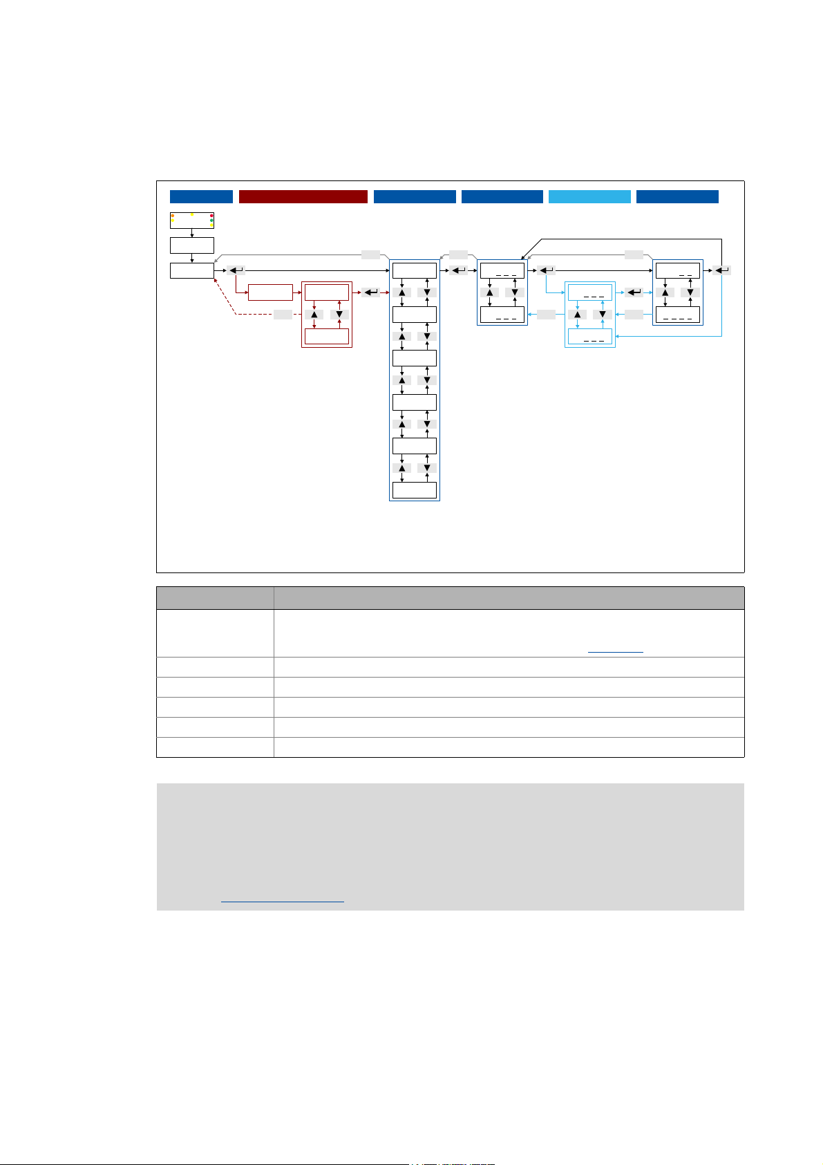
2.3.4 Menu structure
• Without active password protection, the "password" level will be skipped.
• The following applies when changing between the levels "Menu", "Code" and "Subcode":
The keypad records the last selection.
• For codes without subcodes, the "Subcode" level will be skipped.
Menu Info
-0- Access to the parameters of the user menu.
• The user menu of a device serves to create a selection of frequently used parameters to
be able to access and change these parameters quickly. User menu
-1- Access to all drive parameters.
-2- Access to parameters for quick commissioning with terminal control.
-3- Access to parameters for quick commissioning with the integrated keypad.
-4- Access to motor control parameters.
-5- Access to diagnostic/display parameters.
Note!
When the password protection is activated and no password or a wrong password is entered, only the parameters of the user menu can be accessed using the integrated keypad. All other menus/parameters require the correct password.
Password protection
( 23)
( 22)
Lenze · 8400 BaseLine C · Reference manual · DMS 1.6 EN · 01/2014 · TD05 21
Page 22
2 Introduction: Parameterising the controller
2.3 Internal Keypad
_ _ _ _ _ _ _ _ _ _ _ _ _ _ _ _ _ _ _ _ _ _ _ _ _ _ _ _ _ _ _ _ _ _ _ _ _ _ _ _ _ _ _ _ _ _ _ _ _ _ _ _ _ _ _ _ _ _ _ _ _ _ _ _
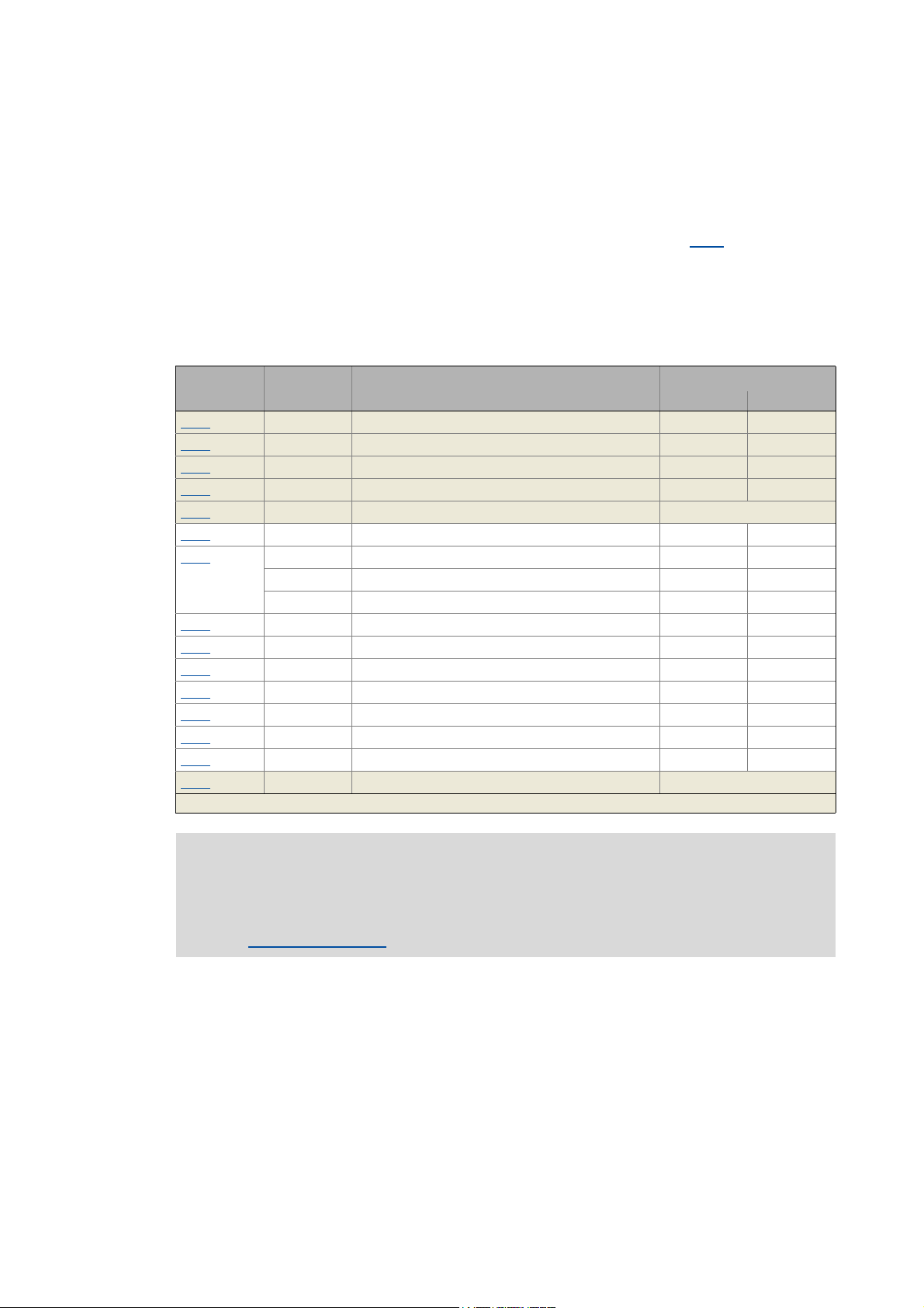
2.3.5 User menu
The user menu (menu -0-) contains a selection of frequently used parameters to be able to access
and change these parameters quickly.
• The integrated keypad serves to change the preset parameter selection in C517
: Enter the codes
the user menu is to contain into the subcodes c001 ...c020. When "0" is set, no entry is displayed
in the user menu.
• The »Engineer« serves to configure the user menu on the User menu tab of the controller. Here,
additional functions are available for loading and saving the parameter selection.
The user menu contains the following parameters:
Code Subcode Info Lenze setting
Value Unit
C051 - Display of actual speed value - rpm
C053 - Display of DC-bus voltage - V
C054 - Display of motor current - A
C061 - Display of heatsink temperature - °C
C137 - Display of device status -
C011
C039
C012
C013
C015
C016
C022
C120
C087 - Rated motor speed 1460 rpm
C099 - Display of firmware version -
Highlighted in grey = display parameter
- Reference speed 1500 rpm
c001 Fixed setpoint 1 40.0 %
c002 Fixed setpoint 2 60.0 %
c003 Fixed setpoint 3 80.0 %
- Acceleration time - main setpoint 2.0 s
- Deceleration time - main setpoint 2.0 s
-V/f base frequency 50.0Hz
- Vmin boost 0.0 %
- Imax in motor mode 47.00 A
- Motor overload threshold (I2xt) 100 %
22
Note!
If the password protection is activated and no password or a wrong password is entered,
only these parameters can be accessed with the integrated keypad.
Password protection
( 23)
Lenze · 8400 BaseLine C · Reference manual · DMS 1.6 EN · 01/2014 · TD05
Page 23
2 Introduction: Parameterising the controller
B
ESC
C
D
E
F
A
8888
3 sec
SAVE
2.3 Internal Keypad
_ _ _ _ _ _ _ _ _ _ _ _ _ _ _ _ _ _ _ _ _ _ _ _ _ _ _ _ _ _ _ _ _ _ _ _ _ _ _ _ _ _ _ _ _ _ _ _ _ _ _ _ _ _ _ _ _ _ _ _ _ _ _ _
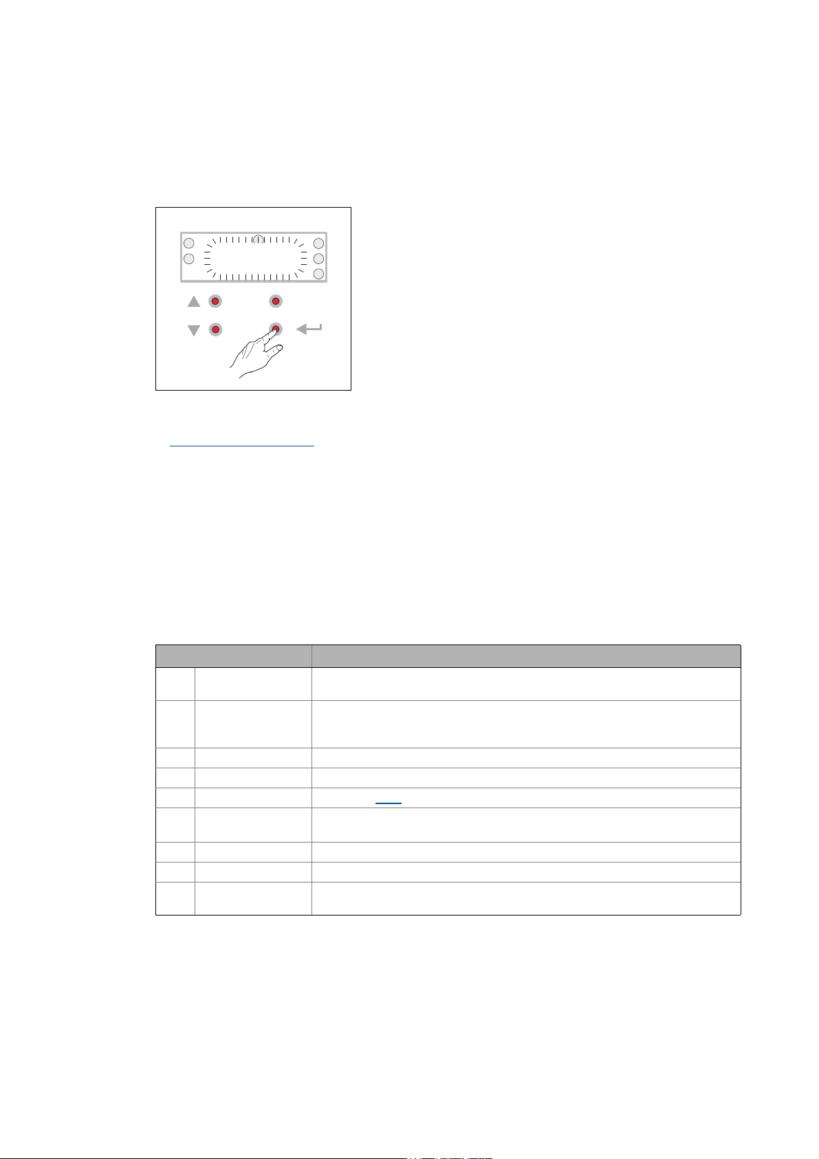
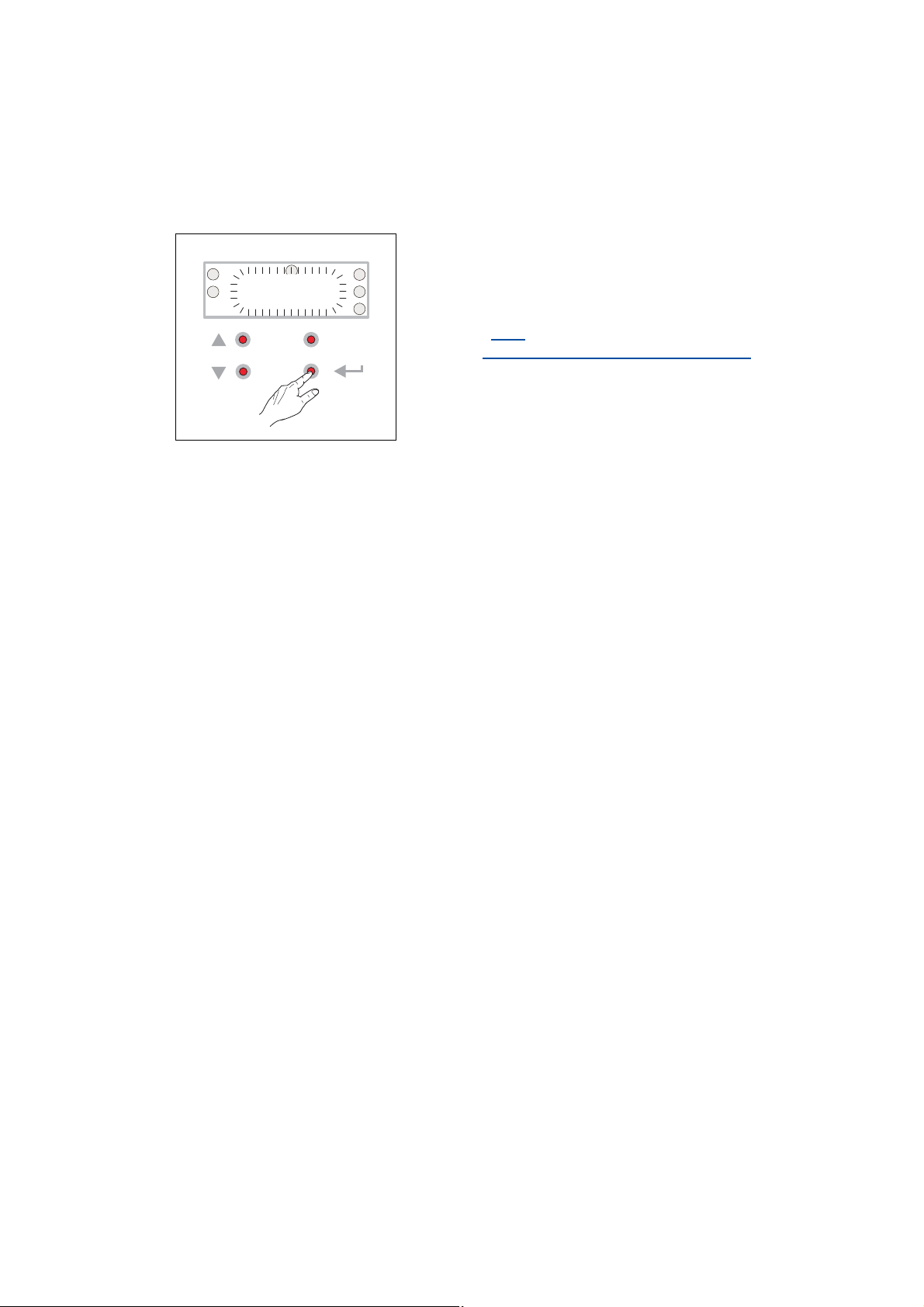
2.3.6 Quick saving of all parameters at the push of a button
Keep the entry button pressed for 3 seconds to save all parameter settings safe against mains failure.
• During the saving process, "SAVE" is blinking in the display.
• After approximately 2 seconds, "SAVE" will disappear from
the display and you can continue your work.
Related topics:
Save parameter settings
( 49)
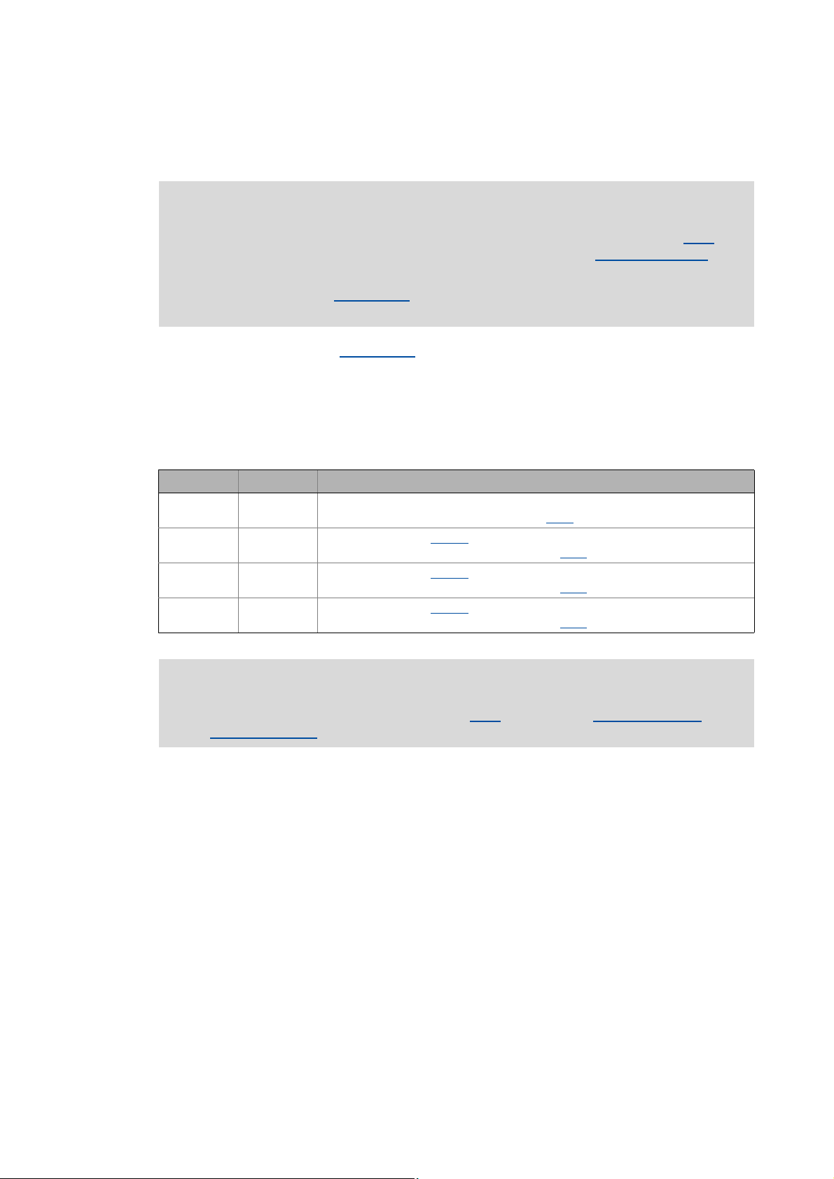
2.3.7 Password protection
The controller offers the option to protect the unauthorised access to the menu level by assigning a
password. The following sections describe how to create, change, or delete the password protection
and how to access the menu level via the password.
Enter password and confirm it
Carry out the steps if you want to create the password protection for the first time for e.g. a controller in default status:
Step Info
1. Mains on After the mains has been switched on and the keypad self test has been completed,
2. ↵ After pressing the enter key:
3. Select menu -1- (all parameters).
4. ↵ Confirm selection.
5. Select code C094
6. ↵ Confirm selection.
7. Set the desired password ("01" ... "9999").
8. ↵ Accept password.
9. ↵ (3 seconds) Keep the entry button pressed for 3 seconds in order to save the parameter settings
"00" is displayed
Wit hout password protection you ha ve fre e acce ss from here to al l menus (and thus
all parameters).
("password").
("00" is now blinking, i.e. entry is possible.)
safe against mains failure.
Lenze · 8400 BaseLine C · Reference manual · DMS 1.6 EN · 01/2014 · TD05 23
Page 24
2 Introduction: Parameterising the controller
2.3 Internal Keypad
_ _ _ _ _ _ _ _ _ _ _ _ _ _ _ _ _ _ _ _ _ _ _ _ _ _ _ _ _ _ _ _ _ _ _ _ _ _ _ _ _ _ _ _ _ _ _ _ _ _ _ _ _ _ _ _ _ _ _ _ _ _ _ _
Change the existing password or deactivate the password protection
Step Info
1. Mains on After the mains has been switched on and the keypad self test has been completed,
2. ↵ After pressing the enter key and with existing password protection:
3. Enter password.
4. ↵ Confirm entry.
5. Select menu -1- (all parameters).
6. ↵ Confirm selection.
7. Select code C094
8. ↵ Confirm selection.
9. Change password: Set new password ("01" ... "9999").
10. ↵ Accept setting.
11. ↵ (3 seconds) Keep the entry button pressed for 3 seconds in order to save the parameter settings
"00" is displayed
"PASS" is displayed for a short time, then "0000".
("password").
(The existing password is now blinking, i.e. a change is possible.)
Deactivate password protection: Set "00".
safe against mains failure.
Access password-protected controller without knowing the password
When the password protection is activated and no password or a wrong password is entered, only
the max. 20 parameters of the user menu
Step Info
1. Mains on After the mains has been switched on and the keypad self test has been completed,
2. ↵ After pressing the enter key and with existing password protection:
3. ↵
or
↵
"00" is displayed
"PASS" is displayed for a short time, then "0000".
After direct confirmation of the value "0000":
• Only the parameters of the user menu
When the wrong password has been entered and confirmed:
• "Err" is displayed for a short time, then only the parameters of the User menu
be selected.
can be accessed.
can be selected.
can
Reach password-protected menu level with knowing the password
Step Info
1. Mains on After the mains has been switched on and the keypad self test has been completed,
2. ↵ After pressing the enter key and with existing password protection:
3. Enter password.
4. ↵ When the correct password has been confirmed:
"00" is displayed
"PASS" is displayed for a short time, then "0000".
You have free access from here to all menus (and thus all parameters).
24
Lenze · 8400 BaseLine C · Reference manual · DMS 1.6 EN · 01/2014 · TD05
Page 25

3 Commissioning
3.1 Safety instructions with regard to commissioning
_ _ _ _ _ _ _ _ _ _ _ _ _ _ _ _ _ _ _ _ _ _ _ _ _ _ _ _ _ _ _ _ _ _ _ _ _ _ _ _ _ _ _ _ _ _ _ _ _ _ _ _ _ _ _ _ _ _ _ _ _ _ _ _
3 Commissioning
The 8400 BaseLine C controller is commissioned in one of the following ways:
• Commissioning with integrated keypad
• If only a few parameters have to be adapted.
• For test/demonstration purposes.
• Commissioning with PC/»Engineer«
• The »Engineer« provides a comfortable access to all parameters of the 8400 BaseLine C controller and hence full flexibility in the commissioning process.
3.1 Safety instructions with regard to commissioning
General safety instructions
In order to prevent injury to persons or damage to material assets
• before connecting the mains voltage
• The wiring for completeness, short circuit, and earth fault
• The "emergency stop" function of the entire system
• The motor circuit configuration (star/delta) must be adapted to the output voltage of the
controller
• The in-phase connection of the motor
• Check the setting of the most important drive parameters before enabling the controller
• The V/f rated frequency must be adapted to the motor circuit configuration!
• The drive parameters relevant for your application must be set correctly!
• The configuration of the I/O terminals must be adapted to the wiring!
• Make sure that no speed setpoint is applied before controller enable
, check
:
.
Safety instructions with regard to motor operation
Danger!
• For thermal reasons, continuous operation of self-ventilated motors at a low field frequency and rated motor current is not permissible!
• If required, activate the Brake resistor monitoring (I2xt)
• With regard to the V/f base frequency (C015
controllers 8400 StateLine/HighLine/TopLine:
For the 8400 BaseLine, the reference voltage for the V/f base frequency is the rated
motor voltage (C090
tage on the supply side).
) according to motor nameplate (independent of the mains vol-
. ( 106)
), observe the following difference to the
Lenze · 8400 BaseLine C · Reference manual · DMS 1.6 EN · 01/2014 · TD05 25
Page 26
3 Commissioning
DI1DI2
DI3
DI4
RFR
X4
24EDO1
12I
AR
A1U
GND
0 10V...
1k
10k
W
...
W
AR
A1U
GND
DI1DI2
DI3
RFR
X4
DO1 12I24E
DI4
3.2 Preparing the 8400 BaseLine for commissioning
_ _ _ _ _ _ _ _ _ _ _ _ _ _ _ _ _ _ _ _ _ _ _ _ _ _ _ _ _ _ _ _ _ _ _ _ _ _ _ _ _ _ _ _ _ _ _ _ _ _ _ _ _ _ _ _ _ _ _ _ _ _ _ _
3.2 Preparing the 8400 BaseLine for commissioning
Danger!
Take all the necessary safety precautions before you carry out the following commissioning steps and switch the device on!
Safety instructions with regard to commissioning
1. Wiring the power connections
• Refer to the mounting instructions supplied with the drive controller to find help on how to
correctly design the power connections to match the requirements of your device.
2. Wire the control connections
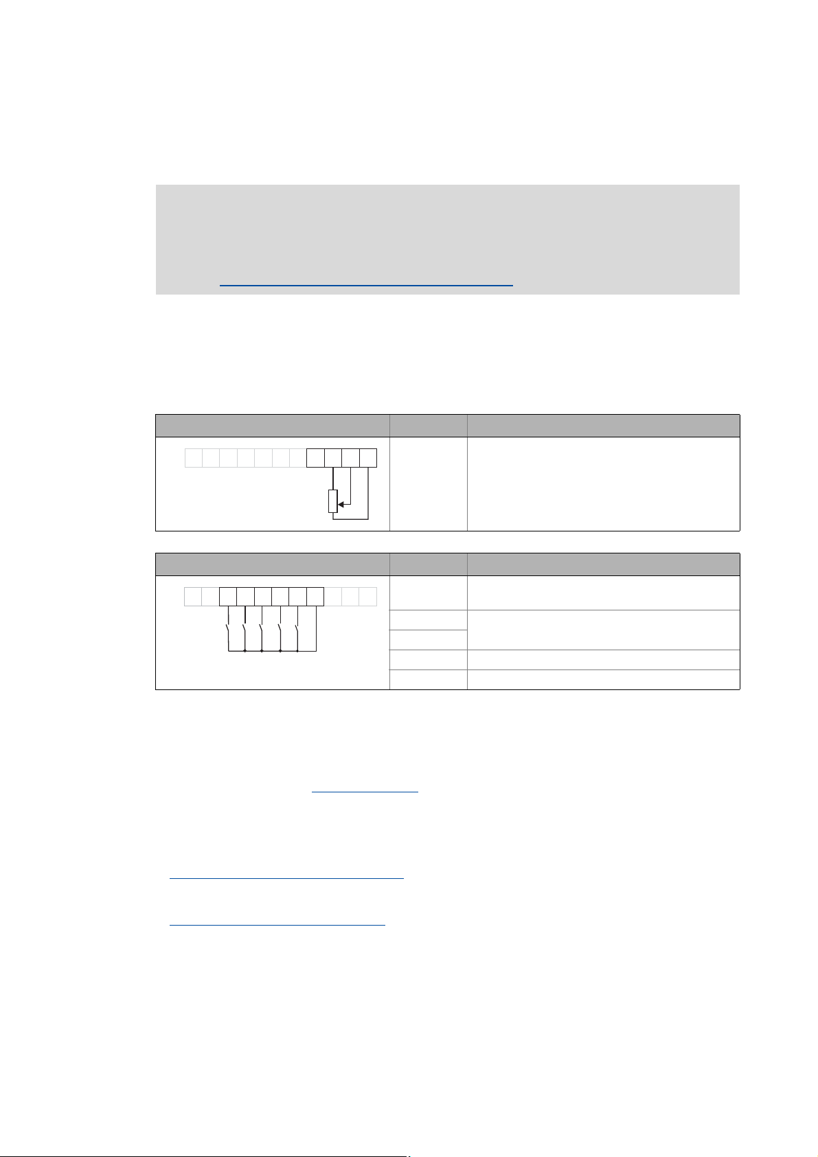
• The following shows the wiring for the Lenze setting.
Analog input at X4 Terminal Function
A1U Setpoint selection
( 25)
• Scaling: 10 V ≡ 100 % ≡ 1500 rpm
(for 4-pole motor)
Digital inputs at X4 Terminal Function
RFR Controller enable: HIGH level
Error reset: HIGH-LOW edge
DI1 Selection fixed setpoint 1 ... 3
DI2
DI1 ... DI4: All HIGH active
DI3 Request DC-injection braking (DCB)
DI4 Request change of direction of rotation
3. Inhibit the controller:
Set terminal X4/RFR to LOW level or open contact to terminal X4/12I .
4. Switch on voltage supply of the controller.
• Information on some operating states can be quickly obtained via the LED display of the integrated keypad. LED status display
( 18)
When the green LED is blinking and the red LED is off, the controller is ready to start and you can
continue with commissioning as required:
Commissioning with integrated keypad
( 27)
or
Commissioning with the »Engineer«
( 31)
Lenze · 8400 BaseLine C · Reference manual · DMS 1.6 EN · 01/2014 · TD05
26
Page 27
3 Commissioning
3.3 Commissioning with integrated keypad
_ _ _ _ _ _ _ _ _ _ _ _ _ _ _ _ _ _ _ _ _ _ _ _ _ _ _ _ _ _ _ _ _ _ _ _ _ _ _ _ _ _ _ _ _ _ _ _ _ _ _ _ _ _ _ _ _ _ _ _ _ _ _ _
3.3 Commissioning with integrated keypad
Only a few parameters need to be adapted for the drive. Afterwards, the drive application can be immediately controlled via the digital and analog inputs of the controller in the preset control mode
"Terminals 0".
Information on how to use the integrated keypad can be found in the chapter entitled
"Internal Keypad
Commissioning steps
In the following, commissioning of the controller using the integrated keypad is described step by
step. Please process the chapters consecutively and execute all steps carefully. This procedure will
help you to commission the controller quickly and as safe as possible:
Load Lenze setting
Parameterise drive/application ( 28)
". ( 17)
Save parameter settings safe against mains failure
Enable controller and select speed
3.3.1 Load Lenze setting
In order to achieve a defined device configuration, it is advisable to make sure that the device is in
its original delivery state. For this purpose, the "Load Lenze setting" device command is available.
Step Info
1. Mains on After the mains has been switched on and the keypad self test has been completed,
2. ↵ After pressing the enter key:
3. Select menu -2-.
4. ↵ Confirm selection.
5. ↵ Confirm first code C002
6. ↵ Confirm subcode c001 ("load Lenze setting").
7. Set value "01" (≡ "Start").
8. ↵ Accept parameter setting to execute the "Load Lenze setting" device command.
( 29)
( 30)
"00" is displayed
Wit hout password protection you ha ve fre e acce ss from here to al l menus (and thus
all parameters).
• The menu -2- contains parameters for quick commissioning with terminal control.
("device commands") of the menu -2-.
Lenze · 8400 BaseLine C · Reference manual · DMS 1.6 EN · 01/2014 · TD05 27
Page 28
3 Commissioning
3.3 Commissioning with integrated keypad
_ _ _ _ _ _ _ _ _ _ _ _ _ _ _ _ _ _ _ _ _ _ _ _ _ _ _ _ _ _ _ _ _ _ _ _ _ _ _ _ _ _ _ _ _ _ _ _ _ _ _ _ _ _ _ _ _ _ _ _ _ _ _ _
3.3.2 Parameterise drive/application
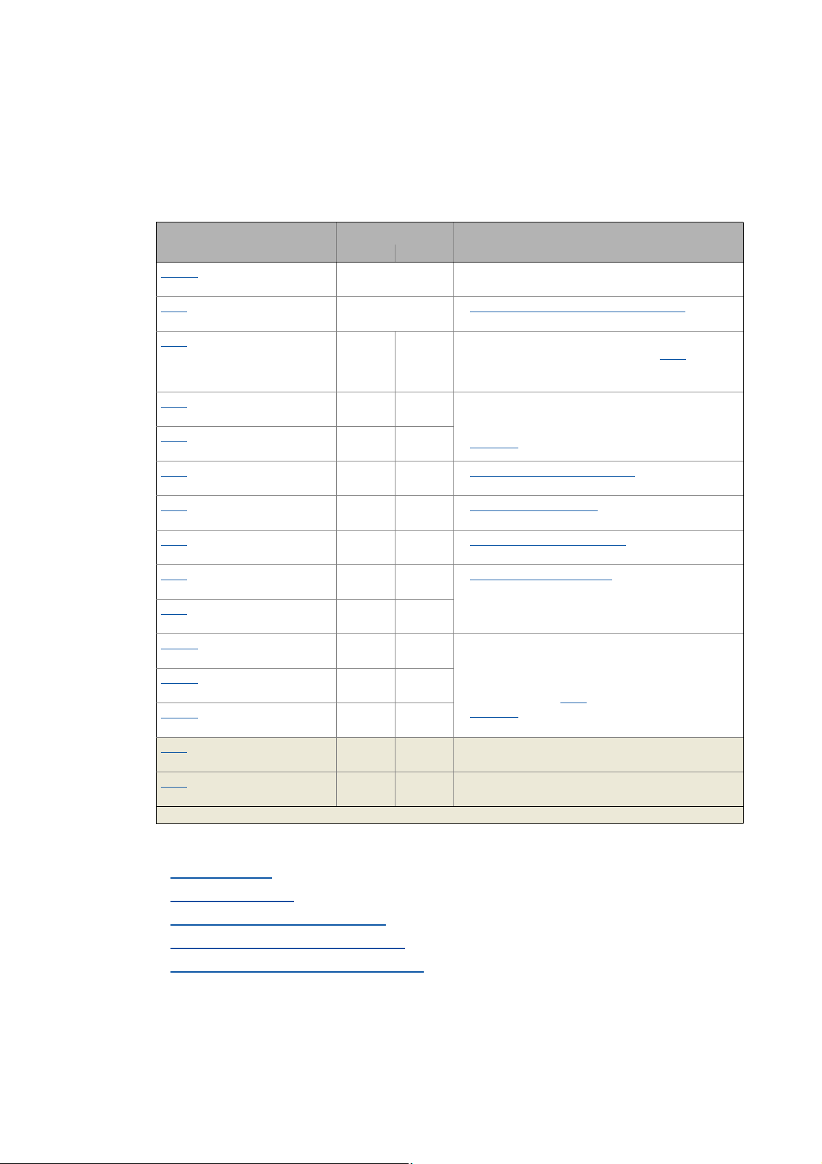
The menu -2- of the integrated keypad contains all basic parameters to commission the drive/application "actuating drive speed" quickly and easily for a terminal control. When you set these parameters to suitable and sensible values, the controller can be operated properly.
Parameter Lenze setting Info
Value Unit
C002/1
Load Lenze setting
C007
Select control mode
C011
Reference speed
C012
Acceleration time - main setpoint
C013
Deceleration time - main setpoint
C015
V/f base frequency
C016
Vmin boost
C022
Current limit (in motor mode)
C087
Rated motor speed
C089
Rated motor frequency
C039/1
Fixed setpoint 1
C039/2
Fixed setpoint 2
C039/3
Fixed setpoint 3
C051
Actual speed value
C054
Current motor current
Highlighted in grey = display parameter
0: Off / ready Reset all parameters to the Lenze setting which are sa-
10: Terminals 0 Terminal assignment of the control modes
1500 rpm All speed setpoint selections are provided in % and al-
2.0 s The setpoint is led via a ramp function generator with li-
2.0 s
50.0 Hz Adapting the V/f base frequency
0.0 % Adapting the Vmin boost
47.00 A Optimising the Imax controller
1460 rpm Motor selection/Motor data
50 Hz
40.0 % A fixed setpoint for the setpoint generator can be acti-
60.0 %
80.0 %
- rpm
- A
ved in the controller firmware.
( 139)
ways refer to the reference speed set in C011
The motor reference speed is given on the motor name-
plate.
near characteristic. The ramp function generator converts setpoint step-changes at the input into a ramp.
L_NSet_1
vated instead of the main setpoint via the digital inputs
DI1 and DI2.
• The fixed setpoints are selected in [%] based on the
reference speed (C011
L_NSet_1
( 309)
( 83)
( 84)
( 85)
( 65)
).
( 309)
.
28
More detailed information on the drive application:
Drive application
Interface description
Setting parameters (short overview)
Pre-assignment of the drive application
Terminal assignment of the control modes
( 121)
( 127)
( 132)
( 133)
( 139)
Lenze · 8400 BaseLine C · Reference manual · DMS 1.6 EN · 01/2014 · TD05
Page 29
3 Commissioning
B
ESC
C
D
E
F
A
8888
3 sec
SAVE
3.3 Commissioning with integrated keypad
_ _ _ _ _ _ _ _ _ _ _ _ _ _ _ _ _ _ _ _ _ _ _ _ _ _ _ _ _ _ _ _ _ _ _ _ _ _ _ _ _ _ _ _ _ _ _ _ _ _ _ _ _ _ _ _ _ _ _ _ _ _ _ _
3.3.3 Save parameter settings safe against mains failure
If parameter settings are changed in the controller, those changes will be lost after mains switching
of the controller unless the settings have been saved explicitly.
• Keep the entry button pressed for 3 seconds in order to save
the parameter settings safe against mains failure.
Tip!
In C141
Automatic saving of parameter changes
, an automatic saving can be activated.
( 49)
Lenze · 8400 BaseLine C · Reference manual · DMS 1.6 EN · 01/2014 · TD05 29
Page 30
3 Commissioning
3.3 Commissioning with integrated keypad
_ _ _ _ _ _ _ _ _ _ _ _ _ _ _ _ _ _ _ _ _ _ _ _ _ _ _ _ _ _ _ _ _ _ _ _ _ _ _ _ _ _ _ _ _ _ _ _ _ _ _ _ _ _ _ _ _ _ _ _ _ _ _ _
3.3.4 Enable controller and select speed
Note!
If the controller is enabled at power-on and the auto-start option is activated in C142 "In-
hibit at power-on" (Lenze setting), the controller remains in the "ReadyToSwitchON
te.
For changing to the "SwitchedON
nal X4/RFR to LOW level or open contact to terminal X4/12I.
When the controller is in the "SwitchedON" state:
1. Enable controller:
Set terminal X4/RFR to HIGH level or close contact to terminal X4/12I n.
2. Select speed:
• In the "Terminals 0" by selecting a voltage at the analog input or by selecting a fixed setpoint
via the digital inputs DI1/DI2.
" state, first deactivate the controller enable: Set termi-
" sta-
DI1 DI2 Speed selection
LOW LOW The setpoint speed is selected via the analog input 1
• Scaling: 10 V ≡ 100 % ≡ reference speed (C011
HIGH LOW The fixed setpoint 1 (C039/1
• Lenze setting: 40 % of the reference speed (C011
LOW HIGH The fixed setpoint 2 (C039/2
• Lenze setting: 60 % of the reference speed (C011
HIGH HIGH The fixed setpoint 3 (C039/3
• Lenze setting: 80 % of the reference speed (C011
) is used as setpoint speed.
) is used as setpoint speed.
) is used as setpoint speed.
)
)
)
)
Note!
Observe the actual speed value (display in C051) as well as the LED status display and
Display messages
Tip!
More control functions in the "Terminals 0" control mode:
• DI3: HIGH level ≡ request DC-injection braking
• DI4: HIGH level ≡ request change of direction of rotation
indicated in the integrated keypad.
30
Lenze · 8400 BaseLine C · Reference manual · DMS 1.6 EN · 01/2014 · TD05
Page 31

3 Commissioning
3.4 Commissioning with the »Engineer«
_ _ _ _ _ _ _ _ _ _ _ _ _ _ _ _ _ _ _ _ _ _ _ _ _ _ _ _ _ _ _ _ _ _ _ _ _ _ _ _ _ _ _ _ _ _ _ _ _ _ _ _ _ _ _ _ _ _ _ _ _ _ _ _
3.4 Commissioning with the »Engineer«
Commissioning with the »Engineer« is suited for every drive task and in particular for drive tasks
with more demanding requirements/more comprehensive parameter setting.
In the following, commissioning of the controller is described step by step. Please process the chapters consecutively and execute all steps carefully. This procedure will help you to commission the
controller quickly and as safe as possible:
Preconditions for commissioning with the »Engineer«
Creating an »Engineer« project & going online
Parameterise drive/application
Save parameter settings safe against mains failure
Enable controller and select speed
3.4.1 Preconditions for commissioning with the »Engineer«
For commissioning, you need
• a PC that satisfies the following requirements:
• processor with 1.4 GHz or higher
• at least 512 MB RAM and 650 MB free hard disc space
• Microsoft® Windows® 2000 operating system (from service pack 2 onwards) or
Windows® XP
• the Lenze »Engineer« PC software
• a connection to the controller, e.g. via USB diagnostic adapter:
• Connect the USB diagnostic adapter to the diagnostic interface X6.
• Connect the USB diagnostic adapter to the PC via a free USB port.
Tip!
How to obtain/update the L-force »Engineer« software:
• Download from the Internet:
The full version of the »Engineer StateLevel« is provided free of charge. Current software
can be found on the Internet in the "Services & Downloads" area under http://
www.Lenze.com.
• Requesting the CD
Yo u c an a ls o re qu est th e L-fo rc e »Eng in eer « s epa ra tel y o n CD fr ee of c ha rge at you r L enz e
representative. See the "About Lenze" area on our homepage for e.g. the corresponding
German address.
Lenze · 8400 BaseLine C · Reference manual · DMS 1.6 EN · 01/2014 · TD05 31
Page 32

3 Commissioning
3.4 Commissioning with the »Engineer«
_ _ _ _ _ _ _ _ _ _ _ _ _ _ _ _ _ _ _ _ _ _ _ _ _ _ _ _ _ _ _ _ _ _ _ _ _ _ _ _ _ _ _ _ _ _ _ _ _ _ _ _ _ _ _ _ _ _ _ _ _ _ _ _
3.4.2 Creating an »Engineer« project & going online
You can find detailed information on the general use of the »Engineer« in the online help
which you can call with [F1].
• In the "Working with projects" chapter, all options of the start-up wizard are described
to create a new »Engineer« project.
The following steps describe the standard procedure of creating a project using the Select
component from catalogue option. Here, you select the single components (controller, motor, etc.)
from selection lists.
1. Start the »Engineer«.
2. Create a new project by means of the Start-up wizard and the Select component from catalogue
option:
•In the Component dialog step, select the 8400 BaseLine C controller.
• Select the other components (motor/gearbox) to be added to the project in the Other
components dialog step.
3. Go online.
• After a successful connection to the controller, the following status is displayed in the Status
line:
4. Download parameter set.
• This command serves to overwrite the current parameter settings in the controller by parameter settings of the »Engineer« project.
32
Lenze · 8400 BaseLine C · Reference manual · DMS 1.6 EN · 01/2014 · TD05
Page 33

3 Commissioning
3.4 Commissioning with the »Engineer«
_ _ _ _ _ _ _ _ _ _ _ _ _ _ _ _ _ _ _ _ _ _ _ _ _ _ _ _ _ _ _ _ _ _ _ _ _ _ _ _ _ _ _ _ _ _ _ _ _ _ _ _ _ _ _ _ _ _ _ _ _ _ _ _
3.4.3 Parameterise drive/application
Go to Workspace and change to the Application parameters tab.
Parameterising the motor control
On the left, the parameters of the motor control are arranged:
1. Go to the Motor control (C006
Note!
In the Lenze setting, the V/f characteristic control (VFCplus) with linear characteristic is
set in C006
• The V/f characteristic control (VFCplus) is an motor control for standard frequency inverter applications based on a simple and robust control process which is suitable for
the operation of machines with linear or square-law load torque characteristic (e.g.
fans).
• The parameter settings have been set in advance in such a way that, if the drive controller and 50 Hz asynchronous machine match each other in terms of performance,
the drive controller is immediately ready for operation without any further parameter
setting work and the motor works satisfactorily.
as motor control.
) list field and select the required motor control.
Lenze · 8400 BaseLine C · Reference manual · DMS 1.6 EN · 01/2014 · TD05 33
Page 34

3 Commissioning
3.4 Commissioning with the »Engineer«
_ _ _ _ _ _ _ _ _ _ _ _ _ _ _ _ _ _ _ _ _ _ _ _ _ _ _ _ _ _ _ _ _ _ _ _ _ _ _ _ _ _ _ _ _ _ _ _ _ _ _ _ _ _ _ _ _ _ _ _ _ _ _ _
2. Adapting the parameters of the motor control:
Parameter Lenze setting Info
Value Unit
V/f base frequency
(C015
)
Imax in motor mode
)
(C022
Vmin boost
)
(C016
50.0 Hz Adapting the V/f base frequency
47.00 A Optimising the Imax controller
0.0 % Adapting the Vmin boost
( 83)
( 85)
( 84)
Tip!
Also check the other information on the nameplate against the motor data set in the drive
controller. You can find further information in the chapter entitled "Motor selection/Motor
data". ( 65)
Recommendations for the following application cases:
• If the controller and motor differ greatly from each other in terms of performance:Set
the Imax limit (in motor mode) in C022
• If a higher starting torque is required:
In idle state of the motor, set the Vmin boost in C016
current flows at a field frequency of f = 3 Hz (display in C058
• If a high torque is to be available at low speed and without a feedback:Select the "sensorless vector control" (SLVC) in C006
to double the rated motor current.
in such a way that the rated motor
).
as motor control.
34
Lenze · 8400 BaseLine C · Reference manual · DMS 1.6 EN · 01/2014 · TD05
Page 35

3 Commissioning
3.4 Commissioning with the »Engineer«
_ _ _ _ _ _ _ _ _ _ _ _ _ _ _ _ _ _ _ _ _ _ _ _ _ _ _ _ _ _ _ _ _ _ _ _ _ _ _ _ _ _ _ _ _ _ _ _ _ _ _ _ _ _ _ _ _ _ _ _ _ _ _ _
Parameterise application
On the right of the Application parameters tab, the parameters of the application are arranged:
1. Select the required control mode in the Control mode (C007
• The corresponding wiring diagram is displayed in a pop-up window if you click the button
right to the list field.
• For a detailed description, see chapter entitled "Terminal assignment of the control modes
( 139)
2. Optional
• For this purpose select the required operating mode in the L_PCTRL_1: Operating mode
• For a detailed description see the function block L_PCTRL_1
• The parameterisation dialog of the process controller can be accessed via the Process
3. Optional
• For this purpose, select "1: On" in the L_MPot_1: Use (C806
• For a detailed description see the function block L_MPot_1
• The parameterisation dialog of the process controller can be accessed via the Motor
: Use process controller.
(C242
) list field.
controller button.
: Use motor potentiometer.
potentiometer button.
) list field.
. ( 312)
) list field.
. ( 305)
".
Lenze · 8400 BaseLine C · Reference manual · DMS 1.6 EN · 01/2014 · TD05 35
Page 36

3 Commissioning
3.4 Commissioning with the »Engineer«
_ _ _ _ _ _ _ _ _ _ _ _ _ _ _ _ _ _ _ _ _ _ _ _ _ _ _ _ _ _ _ _ _ _ _ _ _ _ _ _ _ _ _ _ _ _ _ _ _ _ _ _ _ _ _ _ _ _ _ _ _ _ _ _
4. Adapt parameters of the application:
Parameter Lenze setting Info
Value Unit
Accel. time - main setpoint
(C012
)
Decel. time - main setpoint
(C013
)
Reference speed
)
(C011
Deceleration time - quick
stop
(C105
)
Fixed setpoint 1
(C039/1
Fixed setpoint 2
(C039/2
Fixed setpoint 3
(C039/3
)
)
)
2.0 s The setpoint is led via a ramp function generator with li-
2.0 s
1500 rpm All speed setpoint selections are provided in % and al-
5.0 s When "quick stop" is requested, the motor control is de-
40.0 % A fixed setpoint for the setpoint generator can be acti-
60.0 %
80.0 %
near characteristic. The ramp function generator converts setpoint step-changes at the input into a ramp.
L_NSet_1
ways refer to the reference speed set in C011
The motor reference speed is given on the motor nameplate.
coupled from the setpoint selection and within the deceleration time parameterised in C105
brought to a standstill in (n
Activate/Deactivate quick stop
vated instead of the main setpoint via the digital inputs
DI1 and DI2.
• The fixed setpoints are selected in [%] based on the
reference speed (C011
L_NSet_1
( 309)
( 309)
.
=0).
act
).
, the motor is
( 50)
Tip!
•Via the Signal flow button, you get one dialog level lower to the signal flow of the appli-
cation with further parameterisation opportunities. See chapter entitled
"Parameterisation dialog
• The preconfigured I/O connection in the selected control mode can be changed via configuration parameters. See chapter entitled "User-defined terminal assignment
More detailed information on the drive application:
Drive application
Interface description
( 121)
( 127)
Setting parameters (short overview)
Pre-assignment of the drive application
Terminal assignment of the control modes
". ( 122)
". ( 114)
( 132)
( 133)
( 139)
36
Lenze · 8400 BaseLine C · Reference manual · DMS 1.6 EN · 01/2014 · TD05
Page 37

3 Commissioning
3.4 Commissioning with the »Engineer«
_ _ _ _ _ _ _ _ _ _ _ _ _ _ _ _ _ _ _ _ _ _ _ _ _ _ _ _ _ _ _ _ _ _ _ _ _ _ _ _ _ _ _ _ _ _ _ _ _ _ _ _ _ _ _ _ _ _ _ _ _ _ _ _
3.4.4 Save parameter settings safe against mains failure
In order that parameter settings made in the device do not get lost by means of mains switching,
you must safe the parameter set explicitly safe against mains failure in the device.
• Save parameter set
3.4.5 Enable controller and select speed
Note!
If the controller is enabled at power-on and the auto-start option is activated in C142
(Lenze setting), the controller remains in the "ReadyToSwitchON
For changing to the "SwitchedON
nal X4/RFR to LOW level or open contact to terminal X4/12I.
" state, first deactivate the controller enable: Set termi-
" state (display in C137).
When the controller is in the "SwitchedON" state:
1. Enable controller:
Set terminal X4/RFR to HIGH level or close contact to terminal X4/12I n.
2. Select speed:
• In the "Terminals 0" by selecting a voltage at the analog input or by selecting a fixed setpoint
via the digital inputs DI1/DI2.
DI1 DI2 Speed selection
LOW LOW The setpoint speed is selected via the analog input 1
• Scaling: 10 V ≡ 100 % ≡ reference speed (C011
HIGH LOW The fixed setpoint 1 (C039/1
• Lenze setting: 40 % of the reference speed (C011
LOW HIGH The fixed setpoint 2 (C039/2
• Lenze setting: 60 % of the reference speed (C011
HIGH HIGH The fixed setpoint 3 (C039/3
• Lenze setting: 80 % of the reference speed (C011
) is used as setpoint speed.
) is used as setpoint speed.
) is used as setpoint speed.
)
)
)
)
Note!
Observe the actual speed value (display in C051) as well as the LED status display and
Display messages
indicated in the keypad.
Tip!
More control functions in the "Terminals 0" control mode:
• DI3: HIGH level ≡ request DC-injection braking
• DI4: HIGH level ≡ request change of direction of rotation
Lenze · 8400 BaseLine C · Reference manual · DMS 1.6 EN · 01/2014 · TD05 37
Page 38

3 Commissioning
3.4 Commissioning with the »Engineer«
_ _ _ _ _ _ _ _ _ _ _ _ _ _ _ _ _ _ _ _ _ _ _ _ _ _ _ _ _ _ _ _ _ _ _ _ _ _ _ _ _ _ _ _ _ _ _ _ _ _ _ _ _ _ _ _ _ _ _ _ _ _ _ _
Diagnostics options
When the »Engineer« is used, trouble during commissioning can be detected and eliminated conveniently. Proceed as follows:
• Check whether error messages appear in the »Engineer«.
• You can find a description of each possible message in the chapter entitled "Diagnostics &
error management". ( 145)
• Check the input terminals for their corresponding setpoints.
•The Terminal assignment tab displays the current input/output signals.
• Check the signal flow of the application.
• To do this, open the Application Parameters tab and click on the Signal flow button. The signal flow which is then shown enables a view of the setpoints being applied and their processing.
38
Lenze · 8400 BaseLine C · Reference manual · DMS 1.6 EN · 01/2014 · TD05
Page 39

3 Commissioning
3.5 PC manual control
_ _ _ _ _ _ _ _ _ _ _ _ _ _ _ _ _ _ _ _ _ _ _ _ _ _ _ _ _ _ _ _ _ _ _ _ _ _ _ _ _ _ _ _ _ _ _ _ _ _ _ _ _ _ _ _ _ _ _ _ _ _ _ _
3.5 PC manual control
This function extension is available as of version 03.03.00 and is supported by the »Engineer« as of
version 2.14!
For test and demonstration purposes, PC manual control can be used to manually control various
drive functions via the »Engineer« when an online connection has been established.
Supported drive functions:
• Speed control (follow a speed setpoint)
• Activate/Deactivate quick stop
More control functions:
• Reset of error message
• Set digital/analog outputs (in preparation)
Diagnostic functions:
• Display of the actual speed value and motor current (in a temporal characteristic)
• Display of the current device state
• Display of the status determining error
• Display of the status of the digital/analog inputs (in preparation)
3.5.1 Activating PC manual control
Stop!
PC manual control must be explicitly activated by the user.
If PC manual control is activated, the controller is inhibited via device command (C002/
16) first.
Note!
For activated PC manual control:
The online connection between the PC and the controller is monitored by the controller.
• If the online connection is interrupted for longer than 2 s, error response "Fault" is triggered, i.e. the motor becomes torqueless and is coasting unless it already is at standstill.
PC manual control transmits all required control and setpoint signals to the motor interface.
• The application is now decoupled from these interfaces, but will be processed as before and remains unchanged.
• It does not matter what type of motor control is set in C006
Lenze · 8400 BaseLine C · Reference manual · DMS 1.6 EN · 01/2014 · TD05 39
.
Page 40

3 Commissioning
3.5 PC manual control
_ _ _ _ _ _ _ _ _ _ _ _ _ _ _ _ _ _ _ _ _ _ _ _ _ _ _ _ _ _ _ _ _ _ _ _ _ _ _ _ _ _ _ _ _ _ _ _ _ _ _ _ _ _ _ _ _ _ _ _ _ _ _ _
How to activate PC manual control:
1. If an online connection to the controller has not been established yet:
Go online.
2. Go to Workspace and change to the Application parameters tab.
3. Go to the Overview dialog level and click the PC manual control button.
• The following safety note is displayed first:
•Click the Cancel button to abort the action and close the dialog box.
4. To acknowledge the note and activate PC manual control:
Click the Connect PC manual control button.
• The controller is inhibited via device command (C002/16
•The PC manual control operator dialog is displayed.
).
40
Lenze · 8400 BaseLine C · Reference manual · DMS 1.6 EN · 01/2014 · TD05
Page 41

3 Commissioning
3.5 PC manual control
_ _ _ _ _ _ _ _ _ _ _ _ _ _ _ _ _ _ _ _ _ _ _ _ _ _ _ _ _ _ _ _ _ _ _ _ _ _ _ _ _ _ _ _ _ _ _ _ _ _ _ _ _ _ _ _ _ _ _ _ _ _ _ _
PC manual control operator dialog
On the left-hand side, the PC manual control operator dialog includes control elements which serve
to select various control functions. On the right-hand side, setpoint and status displays are provided
for diagnostic purposes:
Note!
PC manual control can be exited any time by clicking the Close button.
If you exit PC manual control or change to another tab, the controller is inhibited via device command (C002/16
ready is at standstill.
The execution of the various functions is described in the following chapters.
), i.e. the motor becomes torqueless and is coasting unless it al-
Lenze · 8400 BaseLine C · Reference manual · DMS 1.6 EN · 01/2014 · TD05 41
Page 42

3 Commissioning
3.5 PC manual control
_ _ _ _ _ _ _ _ _ _ _ _ _ _ _ _ _ _ _ _ _ _ _ _ _ _ _ _ _ _ _ _ _ _ _ _ _ _ _ _ _ _ _ _ _ _ _ _ _ _ _ _ _ _ _ _ _ _ _ _ _ _ _ _
3.5.2 Speed control
Via the Speed control tab, simply make the drive rotate in the "Speed follower" operating mode without the need to set control parameters or feedback systems:
How to make the motor rotate in its most basic way:
1. Set the desired speed setpoint in [%] based on the reference speed, e.g. directly in the
Setpoint PC input field or via the slider.
•Via the -- / 0 / ++ buttons, the currently set speed setpoint can be reduced/increased in
steps of 10 percent or set to zero.
•Via the Set setpoint A/B buttons, the speed setpoint can be set to a previously set constant value A/B.
2. To start the speed follower:
Enable the controller via the Enable controller button.
• Please observe that the controller will not be enabled if other sources of controller inhibit (e.g. terminal RFR) are active.
• The enabled controller is now following the selected speed setpoint.
• To avoid shocks or overload in case of great setpoint changes, the speed setpoint follows
a linear ramp generator with adjustable acceleration/deceleration time.
•Via the Inhibit controller button, the controller can be inhibited again, i.e. the motor becomes torqueless and is coasting unless it already is at standstill.
42
Lenze · 8400 BaseLine C · Reference manual · DMS 1.6 EN · 01/2014 · TD05
Page 43

3 Commissioning
3.5 PC manual control
_ _ _ _ _ _ _ _ _ _ _ _ _ _ _ _ _ _ _ _ _ _ _ _ _ _ _ _ _ _ _ _ _ _ _ _ _ _ _ _ _ _ _ _ _ _ _ _ _ _ _ _ _ _ _ _ _ _ _ _ _ _ _ _
Further functions:
•If the Set quick stop (QSP) button is clicked, the motor is braked to a standstill within the dece-
leration time parameterised in C105
•Via the Deactivate quick stop (QSP) button, the quick stop can be deactivated.
•Via the << Left and Right >> buttons, the direction of rotation can be changed.
.
Lenze · 8400 BaseLine C · Reference manual · DMS 1.6 EN · 01/2014 · TD05 43
Page 44

4 Device control (DCTRL)
_ _ _ _ _ _ _ _ _ _ _ _ _ _ _ _ _ _ _ _ _ _ _ _ _ _ _ _ _ _ _ _ _ _ _ _ _ _ _ _ _ _ _ _ _ _ _ _ _ _ _ _ _ _ _ _ _ _ _ _ _ _ _ _
4 Device control (DCTRL)
This chapter provides information on the internal device control as well as the device commands
which can be executed via the subcodes of C002
• The device control causes the controller to take defined device states.
• The device control provides a multitude of status information in many ways:
• Optically via the LED status display
• As text messages in the
• As process signals via the outputs of the LS_DriveInterface
• Via diagnostic / display parameters which are included in the »Engineer« parameter list as
well as in the Diagnostics category in the keypad.
Logbook. ( 149)
.
of the integrated keypad. ( 18)
system block. ( 325)
Note!
The device states of the controller are based on the operating states of the CiA402 standard. Device states
( 53)
44 Lenze · 8400 BaseLine C · Reference manual · DMS 1.6 EN · 01/2014 · TD05
Page 45

4 Device control (DCTRL)
_ _ _ _ _ _ _ _ _ _ _ _ _ _ _ _ _ _ _ _ _ _ _ _ _ _ _ _ _ _ _ _ _ _ _ _ _ _ _ _ _ _ _ _ _ _ _ _ _ _ _ _ _ _ _ _ _ _ _ _ _ _ _ _
How to get to the parameterisation dialog of the device control:
1. »Engineer« Go to the Project view and select the 8400 BaseLine C controller.
2. Go to Workspace and change to the Application parameters tab.
3. Go to the Overview dialog level and click the Drive interface button.
Parameterisation dialog in the »Engineer«
The parameterisation dialog shows the input / output signals and the internal signal flow of the
LS_DriveInterface
system block which displays the device control in the application:
Range / Meaning Display parameter
Display of the CAN control word C136/2
Display of the internal state machine and the current device state C137
Display of all active sources of a controller inhibit C158
Display of all active sources of a quick stop C159
Display of the status word of the device control C150
Lenze · 8400 BaseLine C · Reference manual · DMS 1.6 EN · 01/2014 · TD05 45
Page 46

4 Device control (DCTRL)
4.1 Device commands
_ _ _ _ _ _ _ _ _ _ _ _ _ _ _ _ _ _ _ _ _ _ _ _ _ _ _ _ _ _ _ _ _ _ _ _ _ _ _ _ _ _ _ _ _ _ _ _ _ _ _ _ _ _ _ _ _ _ _ _ _ _ _ _
4.1 Device commands
The following subchapters describe the device commands which are provided in the subcodes of
C002
002 and can be carried out using the keypad or, alternatively, the »Engineer« when an online
connection has been established.
The device commands serve to directly control the controller, to organise parameter sets, and to call
diagnostic services.
Regarding the execution of the device commands, a distinction is drawn between:
• Device commands which have an immediate effect on control (e.g. "Activate quick stop")
• After being called in C002/x
or "Off").
• Device commands with longer execution durations (several seconds)
• After being called in C002/x
in progress".
• The execution of the device command has not finished successfully until the "Off / ready" status information is provided in C002/x
• In the event of an error, the "Action cancelled" status information is provided in C002/x
this case, further details can be obtained from the status of the device command executed
last which is displayed in C003
, these device commands provide static status information ("On"
, these device commands provide the status information "Work
.
. In
.
Note!
• Before activating the device commands through a master control, please wait for the
"ready" message of the controller.
• The device will reject a write process to C002/x
message.
• C003
displays the status of the device command executed last..
if the value is >1 and issue an error
Detailed information on the various device commands can be found in the following
subchapters.
• Before you follow the instructions given therein, ensure that you have selected the
controller in the Project view.
46
Lenze · 8400 BaseLine C · Reference manual · DMS 1.6 EN · 01/2014 · TD05
Page 47

4 Device control (DCTRL)
4.1 Device commands
_ _ _ _ _ _ _ _ _ _ _ _ _ _ _ _ _ _ _ _ _ _ _ _ _ _ _ _ _ _ _ _ _ _ _ _ _ _ _ _ _ _ _ _ _ _ _ _ _ _ _ _ _ _ _ _ _ _ _ _ _ _ _ _
Device commands - short overview
C00002
Subcode:
* Subcodes which are not listed are reserved for future extensions.
Device command Controller inhibit re-
1 Load Lenze setting
2 Loading parameter settings
7 Save parameter settings
12 Import EPM data
16 Enable/Inhibit controller
17 Activate/Deactivate quick stop
19 Reset error
21 Delete logbook
23 Identify motor parameters
26 CAN reset node
quired
dynamic
dynamic
dynamic
Status information
dynamic
static
static
static
static
static
static
Activate device command
When an online connection has been established, you can simply use the »Engineer« to activate a
device command by selecting the corresponding option from the Parameter tab in C002/x
("0: Off"
or "1: On / start").
• Alternatively, the device command can also be activated via e.g. keypad or through a master
control by writing to C002/x
.
• Some of the frequently used device commands (such as "Save parameter settings") can also be
executed via toolbar icons of the »Engineer« when an online connection has been established:
Symbol Function
Enable controller
Inhibit controller
Save parameter settings
Note!
Device commands that can be executed via the toolbar of the »Engineers« always affect
the element currently selected in the Project view including all subelements!
• If no controller, but e.g. a system module is selected in the Project view, the correspon-
ding device command will be activated in all lower-level controllers having an online
connection with the »Engineer«.
Before the desired action is carried out, a confirmation prompt appears first, asking whether the action is really to be carried out.
Lenze · 8400 BaseLine C · Reference manual · DMS 1.6 EN · 01/2014 · TD05 47
Page 48

4 Device control (DCTRL)
4.1 Device commands
_ _ _ _ _ _ _ _ _ _ _ _ _ _ _ _ _ _ _ _ _ _ _ _ _ _ _ _ _ _ _ _ _ _ _ _ _ _ _ _ _ _ _ _ _ _ _ _ _ _ _ _ _ _ _ _ _ _ _ _ _ _ _ _
4.1.1 Load Lenze setting
The C002/1 = "1: : On / start" device command resets the parameters to the Lenze setting which are
saved in the controller firmware.
• Can only be executed if the controller is inhibited; otherwise, the feedback C002/1
cess - controller inhibit" will be returned.
• All parameter changes which have been carried out after the last time the parameter settings
were saved will be lost!
• This device command has an effect on the settings of the parameters of the operating system,
application and module.
How to load the Lenze setting:
1. If the controller is enabled, it must be inhibited, e.g. by executing the "Enable/Inhibit controller" device command" (C002/16
2. Execute the "Load Lenze setting" device command
C002/1
The load process may take a couple of seconds. After the device command has been called
in C002/1
4.1.2 Loading parameter settings
The C002/2 = "1: On / start" device command reloads all parameters from the memory module to
the controller.
• Can only be executed if the controller is inhibited; otherwise, the feedback C002/2
cess - controller inhibit" will be returned.
• All parameter changes which have been carried out after the last time the parameter settings
were saved will be lost!
• This device command has an effect on the settings of the parameters of the operating system,
application and module.
="1:On / start"
a dynamic status information ("Work in progress" "Off / ready") is returned.
="6: No ac-
="0:Off / ready").
="6: No ac-
48
Note!
When the device is switched on, all parameters are automatically loaded from the memory module to the main memory of the controller.
How to reload the starting parameter settings from the memory module:
1. If the controller is enabled, it must be inhibited, e.g. by executing the "Enable/Inhibit controller" device command (C002/16
2. Execute the "Load Lenze setting" device command:
C002/2
The load process may take a couple of seconds. After the device command has been called
in C002/2
="1:On / start"
2 a dynamic status information ("Work in progress" "Off / ready") is returned.
="0:Off / ready").
Lenze · 8400 BaseLine C · Reference manual · DMS 1.6 EN · 01/2014 · TD05
Page 49

4 Device control (DCTRL)
4.1 Device commands
_ _ _ _ _ _ _ _ _ _ _ _ _ _ _ _ _ _ _ _ _ _ _ _ _ _ _ _ _ _ _ _ _ _ _ _ _ _ _ _ _ _ _ _ _ _ _ _ _ _ _ _ _ _ _ _ _ _ _ _ _ _ _ _
4.1.3 Save parameter settings
If parameter settings are changed in the controller, those changes will be lost after mains switching
of the controller unless the settings have been saved explicitly.
You have various opportunities to prevent a data loss by saving the parameter settings in the memory module:
• Quick saving of all parameters at the push of a button
• Automatic saving of parameter changes
• Manual saving of parameter settings
( 23)
Note!
How to prevent a data loss:
• Do not switch off the supply voltage during the saving process.
• Only unplug the memory module if the device is switched off.
Automatic saving of parameter changes
Stop!
Activating this function is not permissible if parameters are changed very frequently
(e.g. in case of cyclic writing of parameters via a bus system).
The maximum service life of the memory module amounts to one million writing cycles.
Make sure that this value will not be reached.
When you set the selection "1: Active" in C141/1
every parameter change is automatically saved in the memory module. Thus, manual saving of parameter settings is not required anymore.
Manual saving of parameter settings
The C002/7
mains failure to the memory module of the controller.
= "1: On / start" device command saves the current parameter settings safe against
, the automatic saving function is activated and
Lenze · 8400 BaseLine C · Reference manual · DMS 1.6 EN · 01/2014 · TD05 49
Page 50

4 Device control (DCTRL)
4.1 Device commands
_ _ _ _ _ _ _ _ _ _ _ _ _ _ _ _ _ _ _ _ _ _ _ _ _ _ _ _ _ _ _ _ _ _ _ _ _ _ _ _ _ _ _ _ _ _ _ _ _ _ _ _ _ _ _ _ _ _ _ _ _ _ _ _
4.1.4 Import EPM data
The C002/12 = "1: On / start" device command activates the automatic import of parameters from
the memory module after the error message "PS04: Par.set incompatible".
4.1.5 Enable/Inhibit controller
The C002/16 = "1: On / start" device command enables the controller, provided that no other source
of a controller inhibit is active.
The C002/16
ce of a controller inhibit is active.
• The motor becomes torqueless and coasts down.
• When the controller is inhibited, the status output bCInhActive of the LS_DriveInterface
block is set to TRUE.
• When the controller inhibit request is reset, the drive synchronises to the actual speed. For this
purpose,
• If the flying restart circuit is activated in C990
= "0: : On / start" device command enables the controller, provided that no other sour-
, the flying restart function parameterised in
C991
is used for the synchronisation to the rotary or standing drive. Flying restart function
( 94)
system
Tip!
• The controller can also be enabled or inhibited via the and toolbar icons.
• C158
provides a bit coded representation of all active sources/triggers of a controller in-
hibit.
4.1.6 Activate/Deactivate quick stop
The C002/17 = "1: On / start" device command activates the quick stop function, i.e. the motor control is separated from the setpoint selection, and within the deceleration time parameterised in
C105
the motor is brought to a standstill (n
Parameter Info Lenze setting
C105 Deceleration time - quick stop 2.000 s
• A pulse inhibit (CINH) is set if the "Auto-DCB" function has been activated via C019
The C002/17
other source of a quick stop is active.
= "0: Off / ready" device command deactivates the quick stop again, provided that no
Tip!
C159
provides a bit coded representation of all active sources/triggers of a quick stop.
act
=0).
Value Unit
.
50
Lenze · 8400 BaseLine C · Reference manual · DMS 1.6 EN · 01/2014 · TD05
Page 51

4 Device control (DCTRL)
4.1 Device commands
_ _ _ _ _ _ _ _ _ _ _ _ _ _ _ _ _ _ _ _ _ _ _ _ _ _ _ _ _ _ _ _ _ _ _ _ _ _ _ _ _ _ _ _ _ _ _ _ _ _ _ _ _ _ _ _ _ _ _ _ _ _ _ _
4.1.7 Reset error
The C002/19 = "1: On / start" device command acknowledges an existing error message if the error
cause has been eliminated and thus the error is not pending anymore.
• After resetting the current error, further errors may be pending which must be reset as well.
• The last 8 errors are displayed in C168
.
Tip!
An error message can also be acknowledged by activating the Reset error button in the
Diagnostics tab.
In the Lenze setting, switching RFR also causes an error acknowledgement (see configuration parameter C701/2
Detailed information on error messages can be found in the chapter entitled "Diagnostics
& error management". ( 145)
).
4.1.8 Delete logbook
The C002/21 = "1: On / start" device command deletes all logbook entries.
Tip!
Click the Logbook button in the Diagnostics tab to display the logbook in the »Engineer«.
In the Logbook dialog box, it is also possible to delete all logbook entries by clicking the
Delete button.
Detailed information on the logbook can be found in the chapter entitled "Diagnostics &
error management". ( 145)
4.1.9 Identify motor parameters
The C002/23 = "1: On / start" device command performs automatic identification of the motor pa-
rameters.
• The device command is only executed when the drive controller is in the "SwitchedON
• In order to identify the motor parameters, the controller must be enabled after this device command.
• After that it changes to the "MotorIdent
• After the execution of the identification, it changes back to the "SwitchedON
" state.
" device state.
" device state.
Tip!
Detailed information on automatic identification of motor parameters can be found in the
"Automatic motor data identification
Lenze · 8400 BaseLine C · Reference manual · DMS 1.6 EN · 01/2014 · TD05 51
" subchapter on motor control (MCTRL). ( 70)
Page 52

4 Device control (DCTRL)
4.1 Device commands
_ _ _ _ _ _ _ _ _ _ _ _ _ _ _ _ _ _ _ _ _ _ _ _ _ _ _ _ _ _ _ _ _ _ _ _ _ _ _ _ _ _ _ _ _ _ _ _ _ _ _ _ _ _ _ _ _ _ _ _ _ _ _ _
4.1.10 CAN reset node
The C002/26 = "1: On / start" device command reinitialises the CAN interface which is required after
e.g. changing the data transfer rate, the node address, or identifiers..
General information on the CAN interface can be found in the chapter entitled "System
bus "CAN on board"". ( 169)
52
Lenze · 8400 BaseLine C · Reference manual · DMS 1.6 EN · 01/2014 · TD05
Page 53

4 Device control (DCTRL)
ReadyTo
SwitchOn
3
SwitchedOn
4
Operation
Enabled
5
Trouble
7
0
SafeTorqueOff
10
0
MotorIdent
2
1
Warning
Fault
8
Init
1
Power on
4.2 Device states
_ _ _ _ _ _ _ _ _ _ _ _ _ _ _ _ _ _ _ _ _ _ _ _ _ _ _ _ _ _ _ _ _ _ _ _ _ _ _ _ _ _ _ _ _ _ _ _ _ _ _ _ _ _ _ _ _ _ _ _ _ _ _ _
4.2 Device states
The state machine causes the controller to take defined states:
Device state machine
Grey field: pulse inhibit
Can be reached from all states.
"Warning" contradicts the definition of a device state. In fact, it is a message which is to call attention to the
device state the warning exists for.
"Warning" can occur in parallel to other states.
• The arrows between the device states mark the points where the possible device states begin
and end.
• The digits stand for the state ID (see table below).
Lenze · 8400 BaseLine C · Reference manual · DMS 1.6 EN · 01/2014 · TD05 53
Page 54

4 Device control (DCTRL)
4.2 Device states
_ _ _ _ _ _ _ _ _ _ _ _ _ _ _ _ _ _ _ _ _ _ _ _ _ _ _ _ _ _ _ _ _ _ _ _ _ _ _ _ _ _ _ _ _ _ _ _ _ _ _ _ _ _ _ _ _ _ _ _ _ _ _ _
• The change from one state to another is done in a 1 ms cycle. If, at the same time, several state
change requests exist, the state with the higher priority is processed first (see the following table).
• C137
• C150
displays the current device state.
(status word) provides a bit coded representation of the current device state via bits 8 ... 11
(see table below).
ID Device state
(Display in C137
0 - (reserved) - 0 0 0 0 -
1 Init
2 MotorIdent
3 ReadyToSwitchON
4 SwitchedON
5 OperationEnabled
6 - (reserved) - 0 1 1 0 -
7 Trouble
8 Fault
9 - (reserved) - 1 0 0 1 -
10 SafeTorqueOff
11 - (reserved) - 1 0 1 1 -
... ... ... ... ...
15 - (reserved) - 1 1 1 1 -
Priority Status bits
)
- 0 0 0 1 Initialisation is active
- 0 0 1 0 Motor parameter identification is acti-
Prio 4 0 0 1 1 Device is ready to start
Prio 3 0 1 0 0 Device is switched on
Prio 1 0 1 0 1 Operation
Prio 2 0 1 1 1 Trouble is active
Prio 6 1 0 0 0 Fault is active
Prio 5 1 0 1 0 Safe torque off is active
(display in C150
Bit 11 Bit 10 Bit 9 Bit 8
)
Meaning
ve
[4-1] Device states, priorities, and meaning of the status bits in the status word
54
Lenze · 8400 BaseLine C · Reference manual · DMS 1.6 EN · 01/2014 · TD05
Page 55

4 Device control (DCTRL)
4.2 Device states
_ _ _ _ _ _ _ _ _ _ _ _ _ _ _ _ _ _ _ _ _ _ _ _ _ _ _ _ _ _ _ _ _ _ _ _ _ _ _ _ _ _ _ _ _ _ _ _ _ _ _ _ _ _ _ _ _ _ _ _ _ _ _ _
4.2.1 Init
LED DRIVE READY LED DRIVE ERROR Display in C137 Display in status word 1 (C150)
Bit 11 Bit 10 Bit 9 Bit 8
OFF OFFInit 0001
In the "Init" device status
• is the controller directly after the supply voltage is switched on.
• the operating system is initialised.
• all device components (memory module, power section, etc.) are identified.
• the parameters are read out of the memory module.
• it is checked whether the DC-bus voltage is within the tolerance zone and the precharge relay is
closed.
• the inverter is inhibited, i.e., there is no voltage output at the motor terminals.
• the communication via CAN and diagnostic interface does not work yet.
• the application is not yet processed.
• the monitoring mode is not yet active.
• the controller cannot be parameterised yet and no device commands can be carried out yet.
Note!
If the initialisation is completed, it changes automatically to the "ReadyToSwitchON" device state.
Lenze · 8400 BaseLine C · Reference manual · DMS 1.6 EN · 01/2014 · TD05 55
Page 56

4 Device control (DCTRL)
4.2 Device states
_ _ _ _ _ _ _ _ _ _ _ _ _ _ _ _ _ _ _ _ _ _ _ _ _ _ _ _ _ _ _ _ _ _ _ _ _ _ _ _ _ _ _ _ _ _ _ _ _ _ _ _ _ _ _ _ _ _ _ _ _ _ _ _
4.2.2 MotorIdent
LED DRIVE READY LED DRIVE ERROR Display in C137 Display in status word 1 (C150)
Bit 11 Bit 10 Bit 9 Bit 8
OFF MotorIdent 0 0 1 0
In the "MotorIdent" device state
• is the controller when being in the "SwitchedON
parameters" device command and being enabled.
• the application remains active.
• all system interfaces (IO, bus systems, etc.) remain active.
• error monitoring remains active
• the inverter is controlled independently of the setpoint sources.
" state and having activated the "Identify motor
Stop!
During motor parameter identification, the controller does not respond to setpoint
changes or control processes, (e.g. speed setpoints, quick stop, torque limitations).
After the motor parameter identification is completed, the state changes back to "SwitchedON
Tip!
4.2.3 SafeTorqueOff
In the "SafeTorqueOff" device state
Detailed information on motor parameter identification can be found in the "Automatic
motor data identification" subchapter on motor control. ( 70)
LED DRIVE READY LED DRIVE ERROR Display in C137 Display in status word 1 (C150)
• the controller can only be if a safety module is connected and the power section is supplied and
at least one of the two safe inputs SI1/SI2 is set to LOW level.
• the next transaction to the "ReadyToSwitchON
".
Bit 11 Bit 10 Bit 9 Bit 8
OFF SafeTorqueOff 1 0 1 0
" state takes place.
56
Detailed and important information on the integrated safety system can be found in the
hardware manual!
Lenze · 8400 BaseLine C · Reference manual · DMS 1.6 EN · 01/2014 · TD05
Page 57

4 Device control (DCTRL)
4.2 Device states
_ _ _ _ _ _ _ _ _ _ _ _ _ _ _ _ _ _ _ _ _ _ _ _ _ _ _ _ _ _ _ _ _ _ _ _ _ _ _ _ _ _ _ _ _ _ _ _ _ _ _ _ _ _ _ _ _ _ _ _ _ _ _ _
4.2.4 ReadyToSwitchON
LED DRIVE READY LED DRIVE ERROR Display in C137 Display in status word 1 (C150)
Bit 11 Bit 10 Bit 9 Bit 8
OFF ReadyToSwitchON 0 0 1 1
In the "ReadyToSwitchOn" device state
• is the controller after the initialisation has been completed successfully.
• is the controller even after cancelling "Trouble
• I/O signalare evaluated.
• the monitoring modes are active.
• the controller can be parameterised.
• the application is basically executable.
• prevents in the Lenze setting the auto-start option "Inhibit at power-on" activated in C142
changing to the "SwitchedON
" state.
", "Fault" or "SafeTorqueOff".
Danger!
If the "Inhibit at power-on" auto-start option has been deactivated in C142 the "Ready-
ToSwitchOn" state directly switches to the "SwitchedON
"Inhibit at power-on" auto-start option
( 62)
" state.
from
Lenze · 8400 BaseLine C · Reference manual · DMS 1.6 EN · 01/2014 · TD05 57
Page 58

4 Device control (DCTRL)
4.2 Device states
_ _ _ _ _ _ _ _ _ _ _ _ _ _ _ _ _ _ _ _ _ _ _ _ _ _ _ _ _ _ _ _ _ _ _ _ _ _ _ _ _ _ _ _ _ _ _ _ _ _ _ _ _ _ _ _ _ _ _ _ _ _ _ _
4.2.5 SwitchedON
LED DRIVE READY LED DRIVE ERROR Display in C137 Display in status word 1 (C150)
Bit 11 Bit 10 Bit 9 Bit 8
OFFSwitchedON 0100
In the "SwitchedOn" device state
• is the controller if the user has inhibited the controller (and no error is pending).
• I/O signalare evaluated.
• the monitoring modes are active.
• the controller can be parameterised.
• the application is basically executable.
• it can be changed to the "OperationEnabled
" state by deactivating the controller inhibit.
Tip!
C158
provides a bit coded representation of all active sources/triggers of a controller inhi-
bit.
Depending on certain conditions, a state change takes place based on the "SwitchedOn" device state:
Change condition Changeover to the device state
Control bit "EnableOperation" in control word wCANControl = "1"
AND terminal RFR = HIGH level (controller enable)
Control bit "SwitchOn" = "0". ReadyToSwitchON
Motor parameter identification requested. MotorIdent
Undervoltage in the DC bus. Trouble/Fault (dependent on C600/1)
Error with error response "Trouble" occurs. Trouble
Related topics:
Process data assignment for control via CAN
( 137)
OperationEnabled
58
Lenze · 8400 BaseLine C · Reference manual · DMS 1.6 EN · 01/2014 · TD05
Page 59

4 Device control (DCTRL)
4.2 Device states
_ _ _ _ _ _ _ _ _ _ _ _ _ _ _ _ _ _ _ _ _ _ _ _ _ _ _ _ _ _ _ _ _ _ _ _ _ _ _ _ _ _ _ _ _ _ _ _ _ _ _ _ _ _ _ _ _ _ _ _ _ _ _ _
4.2.6 OperationEnabled
LED DRIVE READY LED DRIVE ERROR Display in C137 Display in status word 1 (C150)
Bit 11 Bit 10 Bit 9 Bit 8
OFFOperationEnabled0101
In the "OperationEnabled" state
• is the controller if the controller inhibit is deactivated and no trouble ("Trouble") and fault
("Fault") are existent.
• the operation is enabled and the motor follows the setpoint defined by the active application
(in case of sensorless vector control only after the magnetisation process is completed).
Depending on certain conditions, a state change takes place based on the "OperationEnabled" device state.
Change condition Changeover to the device state
Control bit "EnableOperation" in control word wCANControl = "0"
OR terminal RFR = LOW level (controller inhibit).
Control bit "SwitchOn" = "0". ReadyToSwitchON
Undervoltage in the DC bus. Trouble/Fault (dependent on C600/1)
Error with error response "Trouble" occurs. Trouble
SwitchedON
Related topics:
Process data assignment for control via CAN
( 137)
Lenze · 8400 BaseLine C · Reference manual · DMS 1.6 EN · 01/2014 · TD05 59
Page 60

4 Device control (DCTRL)
4.2 Device states
_ _ _ _ _ _ _ _ _ _ _ _ _ _ _ _ _ _ _ _ _ _ _ _ _ _ _ _ _ _ _ _ _ _ _ _ _ _ _ _ _ _ _ _ _ _ _ _ _ _ _ _ _ _ _ _ _ _ _ _ _ _ _ _
4.2.7 Trouble
LED DRIVE READY LED DRIVE ERROR Display in C137 Display in status word 1 (C150)
Bit 11 Bit 10 Bit 9 Bit 8
OFF Trouble 0111
In the "Trouble" device state
• is the controller if monitoring has caused a "Trouble" error response.
• the motor has no torque (is coasting) due to the inhibit of the inverter.
Note!
The "Trouble" device state is automatically abandoned if the error cause has been removed.
If in C142
of the controller inhibit is required for leaving the state.
the "Inhibit at trouble" auto-start option is activated , an explicit deactivation
Depending on certain conditions a state change takes place based on the "Trouble" device state.
Change condition Changeover to the device state
The error cause is no longer active. ReadyToSwitchON
Control bit "EnableOperation" in control word wCANControl = "1"
AND terminal RFR = HIGH level (controller enable)
AND the message has been cancelled.
Control bit "EnableOperation" in control word wCANControl = "0"
OR terminal RFR = LOW level (controller inhibit)
AND the message has been cancelled.
Related topics:
Process data assignment for control via CAN
Basics on error handling in the controller
Error messages of the operating system
( 137)
( 145)
( 156)
OperationEnabled
SwitchedON
60
Lenze · 8400 BaseLine C · Reference manual · DMS 1.6 EN · 01/2014 · TD05
Page 61

4 Device control (DCTRL)
4.2 Device states
_ _ _ _ _ _ _ _ _ _ _ _ _ _ _ _ _ _ _ _ _ _ _ _ _ _ _ _ _ _ _ _ _ _ _ _ _ _ _ _ _ _ _ _ _ _ _ _ _ _ _ _ _ _ _ _ _ _ _ _ _ _ _ _
4.2.8 Fault
LED DRIVE READY LED DRIVE ERROR Display in C137 Display in status word 1 (C150)
Bit 11 Bit 10 Bit 9 Bit 8
OFF Fault 1000
In the "Fault" device state
• is the controller if monitoring has caused a "Fault" error response.
• the motor has no torque (is coasting) due to the inhibit of the inverter.
The error must explicitly be reset ("acknowledged") in order to exit the device state, e.g. by the device command "Reset error
" or via the control bit "ResetFault" in the control word wCANControl.
Note!
If an undervoltage in the DC bus of the drive controller occurs (error message "LU"), the
device changes to the "Trouble
" state.
An additional error of higher priority leads the device into the "Fault
According to the Device state machine
state after acknowledging the error although the undervoltage is still available!
If in C142
of the controller inhibit is required for leaving the state.
Related topics:
Process data assignment for control via CAN
Basics on error handling in the controller
Error messages of the operating system
the "Inhibit at fault" auto-start option "is activated, an explicit deactivation
( 145)
( 156)
" state.
, the device changes to the "ReadyToSwitchON"
( 137)
Lenze · 8400 BaseLine C · Reference manual · DMS 1.6 EN · 01/2014 · TD05 61
Page 62

4 Device control (DCTRL)
4.3 "Inhibit at power-on" auto-start option
_ _ _ _ _ _ _ _ _ _ _ _ _ _ _ _ _ _ _ _ _ _ _ _ _ _ _ _ _ _ _ _ _ _ _ _ _ _ _ _ _ _ _ _ _ _ _ _ _ _ _ _ _ _ _ _ _ _ _ _ _ _ _ _
4.3 "Inhibit at power-on" auto-start option
In the Lenze setting inC142 the auto-start option "Inhibit at power-on" is activated. This setting prevents a change to the"SwitchedON
"state if the controller is already enabled at mains power-up.
Danger!
When the auto-start option "Inhibit at power-on" is deactivated, the motor can directly
start after power-on if the controller is enabled!
The following three cases describe the controller behaviour as a function of controller enable and
set auto-start option. Here, we assume that no fault and trouble exist in the controller after poweron and the control bit "EnableOperation" in the control word wCANControl is set to "1".
62
Lenze · 8400 BaseLine C · Reference manual · DMS 1.6 EN · 01/2014 · TD05
Page 63

4 Device control (DCTRL)
W
4.3 "Inhibit at power-on" auto-start option
_ _ _ _ _ _ _ _ _ _ _ _ _ _ _ _ _ _ _ _ _ _ _ _ _ _ _ _ _ _ _ _ _ _ _ _ _ _ _ _ _ _ _ _ _ _ _ _ _ _ _ _ _ _ _ _ _ _ _ _ _ _ _ _
Case 1: No controller enable at power-on
If there is no controller enable at power-on, the controller remains in the "SwitchedON
with controller enable it is changed to the "OperationEnabled
" state, independent of the setting of
" state. Only
the auto-start option:
5)5
&
2SHUDWLRQ(QDEOHG
6ZLWFKHG2Q
5HDG\7R6ZLWFK2Q
,QLW
W
Case 2: Controller enable at power-on and "Inhibit at power-on" activated
If the controller is enabled at power-on and the auto-start option "Inhibit at power-on" is active, the
controller remains in the "ReadyToSwitchON
" state. In order to change to the "SwitchedON" state,
the controller enable must first be deactivated. When the controller enable is then activated, it is
changed to the "OperationEnabled
5)5
&
2SHUDWLRQ(QDEOHG
6ZLWFKHG2Q
5HDG\7R6ZLWFK2Q
,QLW
" state:
W
W
Case 3: Controller enable at power-on and "Inhibit at power-on" deactivated
If in C142
troller is enabled, the "ReadyToSwitchON
terwards to the "OperationEnabled
the auto-start option "option "Inhibit at power-on" is deactivated (bit 0 = 0) and the con-
" state switches directly to the "SwitchedON" state and af-
" state:
5)5
&
2SHUDWLRQ(QDEOHG
6ZLWFKHG2Q
5HDG\7R6ZLWFK2Q
,QLW
W
W
Lenze · 8400 BaseLine C · Reference manual · DMS 1.6 EN · 01/2014 · TD05 63
Page 64

5 Motor control (MCTRL)
_ _ _ _ _ _ _ _ _ _ _ _ _ _ _ _ _ _ _ _ _ _ _ _ _ _ _ _ _ _ _ _ _ _ _ _ _ _ _ _ _ _ _ _ _ _ _ _ _ _ _ _ _ _ _ _ _ _ _ _ _ _ _ _
5 Motor control (MCTRL)
This chapter provides information on the parameter setting of the controller's internal motor control.
Topics:
Motor selection/Motor data
Selecting the control mode
Defining current and speed limits
V/f characteristic control (VFCplus)
Sensorless vector control (SLVC)
Parameterisable additional functions
Braking operation/braking energy management
Monitoring
64 Lenze · 8400 BaseLine C · Reference manual · DMS 1.6 EN · 01/2014 · TD05
Page 65

5 Motor control (MCTRL)
5.1 Motor selection/Motor data
_ _ _ _ _ _ _ _ _ _ _ _ _ _ _ _ _ _ _ _ _ _ _ _ _ _ _ _ _ _ _ _ _ _ _ _ _ _ _ _ _ _ _ _ _ _ _ _ _ _ _ _ _ _ _ _ _ _ _ _ _ _ _ _
5.1 Motor selection/Motor data
The motor data term comprises all parameters that only depend on the motor and that only characterise the electrical behaviour of the machine. The motor data are independent of the application in
which the controller and the motor are used.
Proceed as follows to open the dialog for parameterising the motor data:
1. »Engineer« Go to the Project view and select the 8400 BaseLine C controller.
2. Go to Workspace and change to the Application parameters tab.
3. Go to the Overview dialog level and click the following button:
Parameterisation dialog in the »Engineer«
•Via the from Motor Catalogue button, the motor catalogue can be opened to select another mo-
tor.
Selecting a motor from the motor catalogue in the »Engineer« ( 68)
•Via the From drive... button, the motor data set in the controller can be copied to the »Engineer«
when an online connection has been established.
Lenze · 8400 BaseLine C · Reference manual · DMS 1.6 EN · 01/2014 · TD05 65
Page 66

5 Motor control (MCTRL)
5.1 Motor selection/Motor data
_ _ _ _ _ _ _ _ _ _ _ _ _ _ _ _ _ _ _ _ _ _ _ _ _ _ _ _ _ _ _ _ _ _ _ _ _ _ _ _ _ _ _ _ _ _ _ _ _ _ _ _ _ _ _ _ _ _ _ _ _ _ _ _
Note!
Sensorless vector control in particular requires the motor data parameters to be set. The
motor data comprise the data of the motor nameplate and the data of the motor equivalent circuit.
If the motor has been selected via the motor catalogue of the »Engineer« or the motor
data have been adapted offline using the »Engineer«, all motor data must then be copied to the controller and saved power-failure-proof to the memory module (device
command: C002/11
Motor data
In the parameterisation dialog, the data of the motor nameplate for the selected motor are displayed under "Motor data".
Parameter Info
C081
C087
C088
C089
C090
C091
Rated motor power
Rated motor speed
Rated motor current
Rated motor frequency
Rated motor voltage
Motor cos ϕ
) when an online connection has been established.
Actual values
When an online connection to the controller has been established, the following actual values are
displayed in the parameterisation dialog under "Actual values":
Parameter Info
C051 Actual speed value
C052 Motor voltage
C053 DC-bus voltage
C054 Motor current
C066 Thermal motor load (I2xt)
Highlighted in grey = display parameter
66
Lenze · 8400 BaseLine C · Reference manual · DMS 1.6 EN · 01/2014 · TD05
Page 67

5 Motor control (MCTRL)
5.1 Motor selection/Motor data
_ _ _ _ _ _ _ _ _ _ _ _ _ _ _ _ _ _ _ _ _ _ _ _ _ _ _ _ _ _ _ _ _ _ _ _ _ _ _ _ _ _ _ _ _ _ _ _ _ _ _ _ _ _ _ _ _ _ _ _ _ _ _ _
Adapting motor data manually
If a third party manufacturer's motor is used, the displayed motor data can exactly be adapted to
the real motor by clicking the From project... button and selecting the "Own motor settings" entry
from the Motor selection dialog box afterwards. For this purpose, the data of the motor nameplate
and the equivalent circuit diagram must be available.
Tip!
For a better concentricity factor, we recommend to perform motor parameter identification of the third party manufacturer's motor first. The motor parameters can be manually
adapted afterwards.
Improving the concentricity factor includes
• the adjustment of the inverter error characteristic to the drive system and
• the knowledge of the motor cable resistance.
Both factors are determined in the course of motor parameter identification.
Automatic motor data identification
( 70)
Other motor data
Click the Other motor data... button and go to the Other motor data dialog box including the motor
equivalent circuit:
Parameter Info
C084
C085
C092
C015
C021
Motor stator resistance
Motor stator leakage inductance
Motor magnetising inductance
VFCplus: V/f base frequency
Slip compensation
Lenze · 8400 BaseLine C · Reference manual · DMS 1.6 EN · 01/2014 · TD05 67
Page 68

5 Motor control (MCTRL)
5.1 Motor selection/Motor data
_ _ _ _ _ _ _ _ _ _ _ _ _ _ _ _ _ _ _ _ _ _ _ _ _ _ _ _ _ _ _ _ _ _ _ _ _ _ _ _ _ _ _ _ _ _ _ _ _ _ _ _ _ _ _ _ _ _ _ _ _ _ _ _
5.1.1 Selecting a motor from the motor catalogue in the »Engineer«
If a checkmark is set in the Motor control field in the "Other components" dialog when the controller
is inserted into the project, the motor for the controller can be selected from the motor catalogue in
another dialog:
• Alternatively, the motor can be inserted into the project at a later time via the Insert a
component command.
•Go to the Application parameters tab in the Overview Motor data dialog level and click the
From motor catalogue... button to also reach the motor catalogue for the selection of another
motor.
68
Lenze · 8400 BaseLine C · Reference manual · DMS 1.6 EN · 01/2014 · TD05
Page 69

5 Motor control (MCTRL)
5.1 Motor selection/Motor data
_ _ _ _ _ _ _ _ _ _ _ _ _ _ _ _ _ _ _ _ _ _ _ _ _ _ _ _ _ _ _ _ _ _ _ _ _ _ _ _ _ _ _ _ _ _ _ _ _ _ _ _ _ _ _ _ _ _ _ _ _ _ _ _
Accepting the default values of the motor
If a motor is selected from the motor catalogue at a later time, the Use motor's default values dialog
box is displayed afterwards which includes all motor data of the selected motor. Please select here
which of the default values are to be copied to the controller:
Tip!
If a third party manufacturer's motor is used, select a Lenze motor from the motor catalogue first which is similar in terms of current, voltage and speed rating. Adapt the preselected motor data exactly to the real motor afterwards.
Lenze · 8400 BaseLine C · Reference manual · DMS 1.6 EN · 01/2014 · TD05 69
Page 70

5 Motor control (MCTRL)
5.1 Motor selection/Motor data
_ _ _ _ _ _ _ _ _ _ _ _ _ _ _ _ _ _ _ _ _ _ _ _ _ _ _ _ _ _ _ _ _ _ _ _ _ _ _ _ _ _ _ _ _ _ _ _ _ _ _ _ _ _ _ _ _ _ _ _ _ _ _ _
5.1.2 Automatic motor data identification
Via the "Identify motor parameters" device command " (C002/23), the inverter characteristic, the influences of the motor cable, and the motor parameters listed in the table below can be identified
automatically:
Parameter Info
C015
C016
C021
C084
C085
C092
C095 Motor magnetising current
V/f base frequency
V
boost
min
Slip compensation
Motor stator resistance
Motor stator leakage inductance
Motor magnetising inductance
Danger!
During motor parameter identification, the motor is energised via the outputs U, V and
W of the controller!
Observe the corresponding safety instructions!
Stop!
If motor parameter identification is aborted, unstable drive behaviour may be the result!
Note!
• We strongly recommend motor parameter identification before the initial commissioning of the sensorless vector control (SLVC).
• The motor parameter identification must be carried out when the motor is cold!
• The load machine may remain connected. Holding brakes, if present, may remain in
the braking position.
• With an idling motor, a small angular offset may occur at the motor shaft.
• The amplitude of the rated motor current (C088
sistance. If the rated motor current amounts to less than 60 % of the rated inverter
current, at least 60 % of the rated inverter current will be injected to ensure sufficient
motor parameter identification accuracy.
) is injected to identify the stator re-
70
Lenze · 8400 BaseLine C · Reference manual · DMS 1.6 EN · 01/2014 · TD05
Page 71

5 Motor control (MCTRL)
5.1 Motor selection/Motor data
_ _ _ _ _ _ _ _ _ _ _ _ _ _ _ _ _ _ _ _ _ _ _ _ _ _ _ _ _ _ _ _ _ _ _ _ _ _ _ _ _ _ _ _ _ _ _ _ _ _ _ _ _ _ _ _ _ _ _ _ _ _ _ _
Preconditions
The motor parameters listed in the table below are excluded from automatic identification and
must therefore be adapted to the used motor before motor parameter identification is carried out
(see motor nameplate).
Parameter Info
C081
C087
C088
C089
C090
C091
Duration & sequence of the motor parameter identification
The duration of the motor parameter identification is approx. 30 s. The following steps are carried
out during this time:
Rated motor power
Rated motor speed
Rated motor current
Rated motor frequency
Rated motor voltage
Motor cos ϕ
1. The motor stator resistance (C084
2. The inverter error characteristic is measured.
3. The motor stator leakage inductance (C085
4. The motor magnetising inductance (C092
5. The motor magnetising current (C095
6. The V/f base frequency (C015
7. The slip compensation (C021
8. The V
boost (C016) is detected.
min
) is measured.
) is measured.
) is calculated.
) is calculated.
Note!
Motor parameter identification may be aborted if a special motor (e.g. mid-frequency
motor) is used or if there is a large deviation between inverter and motor power.
Another cause for the abort of the motor parameter identification could be the implausibility of the entered nameplate data, e.g. the entry P = 0 kW for the motor power.
) is measured
) is measured
Lenze · 8400 BaseLine C · Reference manual · DMS 1.6 EN · 01/2014 · TD05 71
Page 72

5 Motor control (MCTRL)
5.1 Motor selection/Motor data
_ _ _ _ _ _ _ _ _ _ _ _ _ _ _ _ _ _ _ _ _ _ _ _ _ _ _ _ _ _ _ _ _ _ _ _ _ _ _ _ _ _ _ _ _ _ _ _ _ _ _ _ _ _ _ _ _ _ _ _ _ _ _ _
How to carry out automatic motor parameter identification:
1. Inhibit the controller if it is enabled, e.g. via the C002/16
at the X4/RFR terminal.
2. Wait until the drive is at standstill.
3. Transfer the nameplate data to the following codes:
• C081
• C087
• C088
• C089
• C090
• C091
4. Start motor parameter identification via the C002/23
5. Enable the controller again.
• Motor parameter identification starts.
• The progress of the identification can be seen in C002/23
• The identification is completed if the "0: Off / ready" message is displayed in C002/23
6. Inhibit controller again.
: Rated motor power
: Rated motor speed
: Rated motor current (according to the connection method /)
: Rated motor frequency (according to the connection method /)
: Rated motor voltage (according to the connection method /)
: Motor cos ϕ
device command or a LOW signal
device command.
.
.
72
Lenze · 8400 BaseLine C · Reference manual · DMS 1.6 EN · 01/2014 · TD05
Page 73

5 Motor control (MCTRL)
5.2 Selecting the control mode
_ _ _ _ _ _ _ _ _ _ _ _ _ _ _ _ _ _ _ _ _ _ _ _ _ _ _ _ _ _ _ _ _ _ _ _ _ _ _ _ _ _ _ _ _ _ _ _ _ _ _ _ _ _ _ _ _ _ _ _ _ _ _ _
5.2 Selecting the control mode
The 8400 BaseLine C controller supports various modes for motor control (open loop or closed loop).
• V/f characteristic control (VFCplus) with linear characteristic is preset.
• The control mode can be selected in the »Engineer« on the Application parameter tab via the
Motor control (C006
) list field:
•A click on the Motor control... button leads you to the parameterisation dialog of the selected
motor control. (The button is labelled according to the selected motor control.)
Tip!
In order to make the selection of the motor control easier, we provide a selection help with
recommendations and alternatives for standard applications in the subchapter entitled
"Selection help
The following section briefly describe the control modes. A reference to more details can be found
at the end of each section.
". ( 75)
Lenze · 8400 BaseLine C · Reference manual · DMS 1.6 EN · 01/2014 · TD05 73
Page 74

5 Motor control (MCTRL)
01
23
n
N
M
N
M
-M
N
-n
N
n
01
23
n
N
M
N
M
-M
N
-n
N
n
5.2 Selecting the control mode
_ _ _ _ _ _ _ _ _ _ _ _ _ _ _ _ _ _ _ _ _ _ _ _ _ _ _ _ _ _ _ _ _ _ _ _ _ _ _ _ _ _ _ _ _ _ _ _ _ _ _ _ _ _ _ _ _ _ _ _ _ _ _ _
V/f characteristic control (VFCplus)
The V/f characteristic control (VFCplus) is a motor control mode for standard frequency inverter applications based on a simple and robust control process which is suitable for the operation of machines with linear or square-law load torque characteristic (e.g. fans). Furthermore, this motor
control mode is also suitable for group drives and special motors. Due to the low parameterisation
effort, commissioning of such applications is fast and easy.
The V
dimensioned for machines with power adaptations to the inverter in the Lenze setting.
V/f characteristic control (VFCplus) ( 78)
Sensorless vector control (SLVC)
Sensorless (field-oriented) vector control is based on a decoupled, separate control for the torqueproducing and the field-producing current component. In addition, the actual speed is reconstructed by means of a motor model so that a speed sensor is not required.
Sensorless vector control (SLVC)
In comparison to the V/f characteristic control without feedback, the following can be achieved by
means of sensorless vector control SLVC:
boost (C016) and slip compensation (C021) required for optimising the drive behaviour are
min
( 87)
• A higher maximum torque throughout the entire speed range
• A higher speed accuracy
• A higher concentricity factor
• A higher level of efficiency
• The implementation of torque-actuated operation with speed limitation
• The limitation of the maximum torque in motor and generator mode for speed-actuated operation
V/f characteristic control (VFCplus) Sensorless vector control (SLVC)
9300vec092 9300vec095
Operation in motor mode (CW rotation) Operation in generator mode (CCW rotation)
Operation in motor mode (CCW rotation) Operation in generator mode (CW rotation)
Tip!
If a high torque without feedback is to be provided at small speeds, we recommend the
"Sensorless vector control" motor control mode.
74
Lenze · 8400 BaseLine C · Reference manual · DMS 1.6 EN · 01/2014 · TD05
Page 75

5 Motor control (MCTRL)
5.2 Selecting the control mode
_ _ _ _ _ _ _ _ _ _ _ _ _ _ _ _ _ _ _ _ _ _ _ _ _ _ _ _ _ _ _ _ _ _ _ _ _ _ _ _ _ _ _ _ _ _ _ _ _ _ _ _ _ _ _ _ _ _ _ _ _ _ _ _
5.2.1 Selection help
To ease the selection of the motor control mode, the two following tables contain recommendations and alternatives to standard applications.
Application Recommended Alternatively
Single drives
With constant load VFCplus: V/f linear SLVC
With extremely alternating loads VFCplus: V/f linear SLVC
With high starting duty SLVC VFCplus: V/f linear
Torque limitation SLVC -
With torque limitation (power control) VFCplus: V/f linear SLVC
Three-phase reluctance motor VFCplus: V/f linear -
Three-phase sliding rotor motor VFCplus: V/f linear -
Three-phase AC motors with permanently assigned frequency/voltage characteristic
Pump and fan drives with quadratic load characteristic VFCplus: V/f quadratic VFCplus or SLVC
Simple hoists VFCplus: V/f linear -
Group drives (several motors connected to controller)
Identical motors and loads VFCplus: V/f linear -
Different motors and/or alternating loads VFCplus: V/f linear -
VFCplus: V/f linear -
[5-1] Standard applications without speed feedback
Lenze · 8400 BaseLine C · Reference manual · DMS 1.6 EN · 01/2014 · TD05 75
Page 76

5 Motor control (MCTRL)
5.3 Defining current and speed limits
_ _ _ _ _ _ _ _ _ _ _ _ _ _ _ _ _ _ _ _ _ _ _ _ _ _ _ _ _ _ _ _ _ _ _ _ _ _ _ _ _ _ _ _ _ _ _ _ _ _ _ _ _ _ _ _ _ _ _ _ _ _ _ _
5.3 Defining current and speed limits
Limitation of the speed setpoint
Parameterising the reference speed in C011
speed setpoint of 100% is specified
All speed setpoint selections are provided in % and always refer to the reference speed set in C011
means that the drive must rotate at the set speed if a
Tip!
For reasons of achievable resolution and the accuracy involved, the reference speed should
be geared to the speed range required for the respective application.
Lenze recommendation: Reference speed (C011
Irrespective of the selected motor control, there are more limitation options:
Parameter Info Lenze setting
C909/1 Max. positive speed 120 %
C909/2
C910/1
C910/2
Max. negative speed 120 %
Max. positive output frequency 1000 Hz
Max. negative output frequency 1000 Hz
) = 1500 ... 3000 rpm
Value Unit
.
Current limitation in motor and generator mode
In the various motor control modes, the controller is provided with functions which determine the
dynamic behaviour under load and counteract exceedance of the maximum current in motor or generator mode.
Parameter Info Lenze setting
Value Unit
C022 Imax in motor mode 47.00 A
C023
Imax in generator mode
• 100 % ≡ Imax in motor mode (C022
100 %
)
The current limits must be selected depending on
• the permissible maximum current of the motor recommendation: I(Mot)
< 1.5 ... 2.0
N
• the permissible maximum current of the inverter
• the torque in motor/generator mode required for the application
76
Lenze · 8400 BaseLine C · Reference manual · DMS 1.6 EN · 01/2014 · TD05
Page 77

5 Motor control (MCTRL)
5.3 Defining current and speed limits
_ _ _ _ _ _ _ _ _ _ _ _ _ _ _ _ _ _ _ _ _ _ _ _ _ _ _ _ _ _ _ _ _ _ _ _ _ _ _ _ _ _ _ _ _ _ _ _ _ _ _ _ _ _ _ _ _ _ _ _ _ _ _ _
Note!
Highly dynamic applications
(that have e.g. too short acceleration/deceleration times or excessively changing loads)
The overcurrent disconnection may respond (fault message OC1), if the setting of the
maximum current in motor mode in C022
permissible value of the respective inverter.
Remedies:
• Increase of the acceleration and deceleration ramp times
• Reduction of the maximum current in motor mode (C022
• Reduction of the maximum current in generator mode (C023
• Adaptation of the indirect peak current limitation (procedure depends on the selected
motor control mode, see below)
• Reduction of the reset time of the current limiting controller (C074/1
approximately corresponds to the maximum
)
)
)
Influencing the torque in motor/generator mode
The torque in motor and generator mode can be limited via the nTorqueMotLim and
nTorqueGenLim process signal inputs.
• If V/f characteristic control (VFCplus) is selected, limitation is indirectly
a so-called I
• If sensorless vector control (SLVC) is selected, the limitation has a direct
torque-producing current component.
If keypad control is selected, the nTorqueMotLim and nTorqueGenLim process signals can
be parameterised via C728/1...2
controller.
max
.
How to adapt the peak current limitation:
V/f characteristic control (VFCplus):
• Reduce the slip compensation with C021
V/f control (VFCplus + encoder):
•Reduce V
Sensorless vector control (SLVC):
• Reduce the slip compensation with C021
• Reduce the limitation of the torque in motor mode via nTorqueMotLimit_a (C728/1
the limitation of the torque in generator mode via nTorqueGenLimit_a (C728/2
boost inC016.
min
performed via
effect on the
.
.
) and
).
Lenze · 8400 BaseLine C · Reference manual · DMS 1.6 EN · 01/2014 · TD05 77
Page 78

5 Motor control (MCTRL)
5.4 V/f characteristic control (VFCplus)
_ _ _ _ _ _ _ _ _ _ _ _ _ _ _ _ _ _ _ _ _ _ _ _ _ _ _ _ _ _ _ _ _ _ _ _ _ _ _ _ _ _ _ _ _ _ _ _ _ _ _ _ _ _ _ _ _ _ _ _ _ _ _ _
5.4 V/f characteristic control (VFCplus)
In case of the V/f characteristic control (VFCplus), the motor voltage of the inverter is determined by
means of a linear or quadratic characteristic depending on the field frequency or motor speed to be
generated. The voltage follows a preselected characteristic.
Stop!
• The following must be observed when operating drives with quadratic V/f characteristic:
• Please always check whether the corresponding drive is suitable for operation with
a quadratic V/f characteristic!
• If your pump drive or fan drive is not suitable for operation with a quadratic V/f
characteristic, you must use either use the V/f characteristic control function with
a linear V/f characteristic or the sensorless vector control (SLVC).
• For adjustment, observe the thermal performance of the connected asynchronous
motor at low output frequencies.
• Usually, standard asynchronous motors with insulation class B can be operated for
a short time with their rated current in the frequency range 0 Hz ≤ f ≤ 25 Hz.
• Contact the motor manufacturer to get the exact setting values for the max. permissible motor current of self-ventilated motors in the lower speed range.
• If you select the quadratic V/f characteristic, we recommend to set a lower V
• The nameplate data of the motor (at least rated speed and rated frequency) must be
entered if, instead of a standard motor, an asynchronous motor is used with the following values:
•rated frequency ≠ 50 Hz (star) or
•rated frequency ≠ 87 Hz (delta) or
• number of pole pairs ≠ 2
min
.
Note!
When the auto DCB threshold is set (C019) > 0 rpm, there is no torque at the motor shaft
in the lower speed range!
Automatic DC-injection braking (Auto-DCB)
5.4.1 Parameterisation dialog/signal flow
Proceed as follows to open the dialog for parameterising the motor control:
1. »Engineer« Go to the Project view and select the 8400 BaseLine C controller.
2. Go to Workspace and change to the Application parameters tab.
3. Select the motor control from the Overview dialog level in the Motor control list field:
• "6: VFCplus: V/f linear" for linear characteristic or
• "8: VFCplus: V/f quadr" for square-law characteristic
4. Click the Motor control V/f button to change to the Overview Motor control V/f dialog
box.
( 97)
78
Lenze · 8400 BaseLine C · Reference manual · DMS 1.6 EN · 01/2014 · TD05
Page 79

Lenze · 8400 BaseLine C · Reference manual · DMS 1.6 EN · 01/2014 · TD05 79
5 Motor control (MCTRL)
5.4 V/f characteristic control (VFCplus)
_ _ _ _ _ _ _ _ _ _ _ _ _ _ _ _ _ _ _ _ _ _ _ _ _ _ _ _ _ _ _ _ _ _ _ _ _ _ _ _ _ _ _ _ _ _ _ _ _ _ _ _ _ _ _ _ _ _ _ _ _ _ _ _
Parameter Info Parameter Info Parameter Info
1 C022 Imax in motor mode 9 C021 Slip compensation 13 C006 Motor control
2 C023 Imax in generator mode 10 C058 Output frequency 14 C015 V/f base frequency
3 C074 Ti Imax controller 11 C910/1 Max. pos. output frequency 15 C016 Vmi n boost
4 C073 Vp Imax controller 12 C910/2 Max. neg. output frequency 16 C018 Switching frequency
5 C050 Speed setpoint
6 C909/1 Max. pos. speed
7 C909/2 Max. neg. speed
8 C105 Deceleration time - quick stop
Page 80

5 Motor control (MCTRL)
01
0
100 %
N
n
n
U
min
U
out
01
0
100 %
N
n
n
U
min
U
out
5.4 V/f characteristic control (VFCplus)
_ _ _ _ _ _ _ _ _ _ _ _ _ _ _ _ _ _ _ _ _ _ _ _ _ _ _ _ _ _ _ _ _ _ _ _ _ _ _ _ _ _ _ _ _ _ _ _ _ _ _ _ _ _ _ _ _ _ _ _ _ _ _ _
5.4.2 Basic settings
The "Initial commissioning steps" listed in the table below are sufficient for a simple characteristic
control.
• Detailed information on the individual steps can be found in the following subchapters.
Initial commissioning steps
1. Defining the V/f characteristic shape
2. Defining current limits (Imax controller)
. ( 80)
. ( 81)
Tip!
Information on the optimisation of the control mode and the adaptation to the real application is provided in the "Optimise control behaviour
Parameterisable additional functions are described correspondingly in the
"Parameterisable additional functions
" chapter. ( 92)
" chapter. ( 82)
5.4.2.1 Defining the V/f characteristic shape
Generally, two different characteristic shapes can be defined:
1. Linear V/f characteristic:
For drives for a constant, speed-independent load torque.
2. Quadratic V/f characteristic:
For drives with a load torque curve which is quadratic or in relation to speed. Quadratic V/f cha-
[5-2] Principle of a linear and quadratic V/f characteristic
racteristics are preferred in the case of centrifugal pumps and fan drives.
The V/f characteristic shape is defined by selecting the corresponding motor control mode in C006:
• "6: VFCplus: V/f linear" for linear characteristic
• "8: VFCplus: V/f quadr" for square-law characteristic
80
Lenze · 8400 BaseLine C · Reference manual · DMS 1.6 EN · 01/2014 · TD05
Page 81

5 Motor control (MCTRL)
5.4 V/f characteristic control (VFCplus)
_ _ _ _ _ _ _ _ _ _ _ _ _ _ _ _ _ _ _ _ _ _ _ _ _ _ _ _ _ _ _ _ _ _ _ _ _ _ _ _ _ _ _ _ _ _ _ _ _ _ _ _ _ _ _ _ _ _ _ _ _ _ _ _
5.4.2.2 Defining current limits (Imax controller)
The V/f characteristic control (VFCplus) is provided with a current limitation control which is decisive for the dynamic behaviour under load and counteracts exceedance of the maximum current in
motor or generator mode. This current limitation control is called I
• The efficiency (motor current) measured by the I
value for motor load set in C022
• If the current limit values are exceeded, the controller changes its dynamic behaviour.
Motor overload during acceleration
The controller prolongs the acceleration ramp to keep the current on or below the current limit.
Generator overload during deceleration
The controller prolongs the deceleration ramp to keep the current on or below the current limit.
Increasing load with constant speed
• If the motor current limit value is reached:
• The controller reduces the effective speed setpoint until a stable working point is set or an
effective speed setpoint of 0 rpm is reached.
• If the load is reduced, the controller increases the effective speed setpoint until the setpoint
speed is reached or the load reaches the current limit value again.
• When the generator current limit value is reached:
• The controller increases the effective speed setpoint until a stable working point is set or the
maximally permissible speed (C909
• If the load is reduced, the controller reduces the effective speed setpoint until the setpoint
speed is reached or the load reaches the current limit value again.
• If a sudden load is built up at the motor shaft (e.g. drive is blocked), the overcurrent disconnection may respond (fault message OC1).
and the current limit value for generator mode set in C023.
) or output frequency (C910).
control is compared with the current limit
max
max
control.
Lenze · 8400 BaseLine C · Reference manual · DMS 1.6 EN · 01/2014 · TD05 81
Page 82

5 Motor control (MCTRL)
5.4 V/f characteristic control (VFCplus)
_ _ _ _ _ _ _ _ _ _ _ _ _ _ _ _ _ _ _ _ _ _ _ _ _ _ _ _ _ _ _ _ _ _ _ _ _ _ _ _ _ _ _ _ _ _ _ _ _ _ _ _ _ _ _ _ _ _ _ _ _ _ _ _
5.4.3 Optimise control behaviour
The V/f characteristic control (VFCplus) is generally ready for operation. It can be adapted subsequently by adapting the characteristic and/or the drive behaviour.
Adapting characteristic
For the linear and quadratic characteristic, it is also possible to match its curve to different load profiles or motors by adapting the V/f base frequency (C015
Adapting the V/f base frequency
Adapting the Vmin boost
Adapting drive behaviour
• Limitation of the maximum current by a current limitation controller (e.g. to prevent the motor
from stalling or to limit to the maximally permissible motor current).
controller ( 85)
• Adaptation of the field frequency by a load-dependent slip compensation (improved speed accuracy for systems without feedback)
( 84)
( 83)
) and the V
-boost (C016) .
min
Optimising the Imax
82
Lenze · 8400 BaseLine C · Reference manual · DMS 1.6 EN · 01/2014 · TD05
Page 83

5 Motor control (MCTRL)
3
5.4 V/f characteristic control (VFCplus)
_ _ _ _ _ _ _ _ _ _ _ _ _ _ _ _ _ _ _ _ _ _ _ _ _ _ _ _ _ _ _ _ _ _ _ _ _ _ _ _ _ _ _ _ _ _ _ _ _ _ _ _ _ _ _ _ _ _ _ _ _ _ _ _
5.4.3.1 Adapting the V/f base frequency
The V/f base frequency (C015) determines the slope of the V/f characteristic and has considerable
influence on the current, torque, and power performance of the motor.
• The setting in C015
• Mains fluctuations or fluctuations of the DC-bus voltage (operation in generator mode) do not
need to be considered when the V/f base frequency is set. They are automatically compensated
for by the internal mains voltage compensation of the device.
• Depending on the setting in C015
verse the entire speed range of the motor.
applies to all permitted mains voltages.
, it may be required to adapt the reference speed (C011) to tra-
• In standard applications, the V/f base frequency (C015
quency (C089
• Reference voltage for the V/f base frequency is the rated motor voltage (C090
tor nameplate.
) as a typical value and corresponds to the data of the motor nameplate.
) is set to the value of the rated motor fre-
Note!
87-Hz operation
4-pole asynchronous motors which are designed for a rated frequency of f = 50 Hz in star
connection can be operated in delta connection when being constantly excited up to f =
87 Hz.
•Advantages:
• Higher speed-setting range
• 73% higher power output in case of standard motors
• Motor current and motor power increase by the factor .
• The field weakening range starts above 87 Hz.
• Generally, this process can also be used with motors which have different numbers of
pole pairs. In case of 2-pole asynchronous motors, the mechanical limit speed must be
maintained.
) according to mo-
Lenze · 8400 BaseLine C · Reference manual · DMS 1.6 EN · 01/2014 · TD05 83
Page 84

5 Motor control (MCTRL)
C00015
C00016
C00015
2
C00016
2
V[V]
out
f[Hz]
V
(100 %)
rmot
1/N/PE AC 264 V
3/PE AC 264 V
3/PE AC 550 V
1/N/PE AC 180 V
3/PE AC 100 V
3/PE AC 320 V
C00015
C00016
V[V]
out
f[Hz]
V
(100 %)
rmot
1/N/PE AC 264 V
3/PE AC 264 V
3/PE AC 550 V
1/N/PE AC 180 V
3/PE AC 100 V
3/PE AC 320 V
5.4 V/f characteristic control (VFCplus)
_ _ _ _ _ _ _ _ _ _ _ _ _ _ _ _ _ _ _ _ _ _ _ _ _ _ _ _ _ _ _ _ _ _ _ _ _ _ _ _ _ _ _ _ _ _ _ _ _ _ _ _ _ _ _ _ _ _ _ _ _ _ _ _
5.4.3.2 Adapting the Vmin boost
The V
boost (C016) of the motor voltage serves to select a load independent magnetising current
min
which is required for asynchronous motors. The torque behaviour of the motor can be optimised by
adapting the setting in C016
.
Note!
The V
The general linear and quadratic V/f characteristics are shown in the illustrations below. The illustrations show the impacts of the parameters used to adapt the characteristic shape.
boost has an effect on output frequencies below the V/f base frequency (C015).
min
[5-3] Representation of the linear V/f characteristic (on the left) and quadratic V/f characteristic (on the right)
To set the V
boost, proceed as follows:
min
1. Operate motor in idle state at approx. 6 % of the rated motor speed.
2. Increase V
Motor in short-time operation up to 0.5 n
• for self-ventilated motors: I
• for forced ventilated motors: I
Motor in continuous operation up to 0.5 n
• for self-ventilated motors: I
• for forced ventilated motors: I
boost (C016) until the following motor current is reached:
min
N
≈ I
Motor
Motor
Motor
≈ 0.8 I
Motor
N Motor
≈ I
N Motor
≈ I
N Motor
N
N Motor
Note!
V
boost is automatically calculated by the motor parameter identification using the
min
data specified on the motor nameplate so that a no-load current of approx. 0.8 I
results at the slip frequency of the machine.
motor
rated
84
Lenze · 8400 BaseLine C · Reference manual · DMS 1.6 EN · 01/2014 · TD05
Page 85

5 Motor control (MCTRL)
5.4 V/f characteristic control (VFCplus)
_ _ _ _ _ _ _ _ _ _ _ _ _ _ _ _ _ _ _ _ _ _ _ _ _ _ _ _ _ _ _ _ _ _ _ _ _ _ _ _ _ _ _ _ _ _ _ _ _ _ _ _ _ _ _ _ _ _ _ _ _ _ _ _
5.4.3.3 Optimising the Imax controller
Using the Lenze setting of the current limitation controller, the drive is stable:
Parameter Info Lenze setting
Value Unit
C073 VFC: Vp Imax controller 0.25
C074
Most applications do not require optimisation.
The setting of the current limitation controller must be adapted if
• power control including great moments of inertia is performed.
• Recommendation: Increase of the reset time Ti (C074
• overcurrent errors occur due to load impulses or too high acceleration ramps.
• Recommendation: Reduction of the gain Vp (C073
roller.
VFC: Ti Imax controller 65 ms
) of the I
controller.
max
) and reset time Ti (C074) of the I
max
cont-
5.4.3.4 Torque limitation
The previous chapter, "Optimising the Imax controller", describes how the drive can be protected
from overload. During commissioning, these settings are carried out once and remain unchanged
afterwards. However, it is often necessary to limit the torque to a lower value for plant or process
reasons.
• To avoid overload in the drive train, the torque in motor mode can be limited via the
nTorqueMotLimit_a process input signal, and the torque in generator mode can be limited via
the nTorqueGenLimit_a process input signal:
Identifier
DIS code | data type
nTorqueMotLimit_a
C830/4 | INT
nTorqueGenLimit_a
C830/5 | INT
Note!
• The accuracy of the torque limitation is limited because the actual torque (C056/2) is
only calculated from the slip speed measured indirectly via the motor current. For this
purpose, the correct entry of the motor data is required. Motor selection/Motor
data ( 65)
• To avoid instabilities during operation with active slip compensation, the torque limit
values are internally processed as absolute values.
• If slip compensation is deactivated (C021
(differential signal between apparent motor current and nTorqueMotLimit_a or
nTorqueGenLimit_a). Above the no-load current of the motor, the accuracy of the indirect torque limitation is limited.
Information/possible settings
Torque limitation in motor mode
• Scaling: 16384 ≡ 100 % M
• Setting range: 0 … +199.9 %
• If keypad control is performed: Parameterisable via C728/1
Torque limitation in generator mode
• Scaling: 16384 ≡ 100 % M
• Setting range: -199.9 ... 0 %
• If keypad control is performed: Parameterisable via C728/2
max
max
(C057)
(C057)
= 0) indirect torque limitation is executed
.
.
Lenze · 8400 BaseLine C · Reference manual · DMS 1.6 EN · 01/2014 · TD05 85
Page 86

5 Motor control (MCTRL)
5.4 V/f characteristic control (VFCplus)
_ _ _ _ _ _ _ _ _ _ _ _ _ _ _ _ _ _ _ _ _ _ _ _ _ _ _ _ _ _ _ _ _ _ _ _ _ _ _ _ _ _ _ _ _ _ _ _ _ _ _ _ _ _ _ _ _ _ _ _ _ _ _ _
5.4.4 Remedies for undesired drive behaviour
Drive behaviour Remedy
Inadequately smooth running at low speeds, especially
in the case of operation with a long motor cable
Problems in case of high starting duty (great mass inertia)
Drive does not follow the speed setpoint. The current controller intervenes in the set field frequen-
Insufficient speed constancy at high load (setpoint and
motor speed are not proportional anymore)
Controller cannot follow dynamic processes, i.e. too
short acceleration/deceleration times in terms of load
ratios.
Automatic motor data identification
Adapting the Vmin boost
cy to limit the controller output current to the maximum
current (C0022, C0023). Therefore:
• Prolong acceleration/deceleration time:
: Acceleration time - main setpoint
C012
: Deceleration time - main setpoint
C013
• Consider a sufficient magnetising time of the motor.
Depending on the motor power, the magnetising
time amounts to 0.1 ... 0.2 s.
• Increase permissible maximum current:
: Imax in motor mode
C022
: Imax in generator mode)
C023
•Increase slip compensation (C021
Important: Unstable drive due to overcompensation!
• With cyclic load impulses (e. g. centrifugal pump), a
smooth motor characteristic is achieved by smaller
values in C021
• Increase the gain of the I
• Reduce the reset time of the I
• Increase acceleration time (C012
• Increase deceleration time (C013)
(possibly negative values).
( 84)
max
( 70)
).
controller (C073)
controller(C074)
max
86
Lenze · 8400 BaseLine C · Reference manual · DMS 1.6 EN · 01/2014 · TD05
Page 87

5 Motor control (MCTRL)
5.5 Sensorless vector control (SLVC)
_ _ _ _ _ _ _ _ _ _ _ _ _ _ _ _ _ _ _ _ _ _ _ _ _ _ _ _ _ _ _ _ _ _ _ _ _ _ _ _ _ _ _ _ _ _ _ _ _ _ _ _ _ _ _ _ _ _ _ _ _ _ _ _
5.5 Sensorless vector control (SLVC)
Sensorless vector control (SLVC) is based on a better motor current control according to the Lenze
FTC process.
Stop!
• The connected motor must not be more than two power classes smaller than the motor assigned to the controller.
• Operation of the sensorless vector control (SLVC) is only permissible for one single drive!
• Operation of the sensorless vector control (SLVC) is not
• The Lenze setting permits the operation of a power-adapted motor. Optimal operation is only possible if either
• the motor is selected via the Lenze motor catalogue
• the motor nameplate data are entered and motor parameter identification is carried out afterwards
- or -
• the nameplate data and equivalent circuit data of the motor (motor leakage inductance and mutual motor inductance, slip compensation and motor stator resistance) are entered manually.
• When you enter the motor nameplate data, take into account the phase connection
implemented for the motor (star or delta connection). Only enter the data applying to
the selected connection type.
• In this context, also observe the instructions in the chapter entitled "Adapting the
V/f base frequency" relating to V/f characteristic control. ( 83)
:
permissible for hoists!
Note!
Optimal operation of the sensorless vector control (SLVC) can be achieved from a minimum speed of approx. 0.5-fold slip speed. At lower speed values below the 0.5-fold slip
speed, the maximum torque is reduced.
The maximum field frequency with this motor control mode is 650 Hz.
In comparison to the V/f characteristic control without feedback, the following can be achieved by
means of sensorless vector control SLVC:
• A higher maximum torque throughout the entire speed range
• A higher speed accuracy
• A higher concentricity factor
• A higher level of efficiency
• The limitation of the maximum torque in motor and generator mode for speed-actuated operation
Lenze · 8400 BaseLine C · Reference manual · DMS 1.6 EN · 01/2014 · TD05 87
Page 88

5 Motor control (MCTRL)
5.5 Sensorless vector control (SLVC)
_ _ _ _ _ _ _ _ _ _ _ _ _ _ _ _ _ _ _ _ _ _ _ _ _ _ _ _ _ _ _ _ _ _ _ _ _ _ _ _ _ _ _ _ _ _ _ _ _ _ _ _ _ _ _ _ _ _ _ _ _ _ _ _
5.5.1 Parameterisation dialog
Proceed as follows to open the dialog for parameterising the motor control:
1. »Engineer« Go to the Project view and select the 8400 BaseLine C controller.
2. Go to Workspace and change to the Application parameters tab.
3. Select the motor control "4: SLVC: Vector control" from the Overview dialog level in the
Motor control (C006
4. Click the Motor control vector button to change to the Overview Motor control vector di-
alog box.
• This dialog level lists shows all relevant parameters in a parameter list.
Short overview of the relevant parameters:
Parameter Info
C006
C011
C018
C021
C022
C023
C050 Speed setpoint
C057 Maximum torque
C058 Output frequency
C081
C084
C085
C087
C088 Rated motor current
C089
C090
C091 Motor cosine phi
C092
C095
C097
C105
C909/1
C909/2
C910/1
C910/2
Highlighted in grey = display parameter
) list field.
Selection of the motor control
"4: SLVC: Vector control"
Reference speed
Switching frequency
Slip compensation
Imax in motor mode
Imax in generator mode
Rated motor power
Motor stator resistance
Motor stator leakage inductance
Rated motor speed
Rated motor frequency
Rated motor voltage
Motor magnetising inductance
Motor magnetising current
Rated motor torque
Deceleration time - quick stop
Max. pos. speed
Max. neg. speed
Max. pos. output frequency
Max. neg. output frequency
88
Lenze · 8400 BaseLine C · Reference manual · DMS 1.6 EN · 01/2014 · TD05
Page 89

5 Motor control (MCTRL)
5.5 Sensorless vector control (SLVC)
_ _ _ _ _ _ _ _ _ _ _ _ _ _ _ _ _ _ _ _ _ _ _ _ _ _ _ _ _ _ _ _ _ _ _ _ _ _ _ _ _ _ _ _ _ _ _ _ _ _ _ _ _ _ _ _ _ _ _ _ _ _ _ _
5.5.2 Speed control with torque limitation
A speed setpoint is selected and the drive system is operated in a speed-controlled manner.
The operational performance can be adapted in the following ways:
• Overload limitation in the drive train
• The torque is limited via the torque setpoint.
• The torque setpoint is identical to the value at the output of the speed controller,
nOutputSpeedCtrl.
• To avoid overload in the drive train, the torque in motor mode can be limited via the
nTorqueMotLimit_a process input signal, and the torque in generator mode can be limited via
the nTorqueGenLimit_a process input signal:
Identifier
DIS code | data type
nTorqueMotLimit_a
C830/4 | INT
nTorqueGenLimit_a
C830/5 | INT
Information/possible settings
Torque limitation in motor mode
• Scaling: 16384 ≡ 100 % M
• Setting range: 0 … +199.9 %
• If keypad control is performed: Parameterisable via C728/1
Torque limitation in generator mode
• Scaling: 16384 ≡ 100 % M
• Setting range: -199.9 ... 0 %
• If keypad control is performed: Parameterisable via C728/2
max
max
(C057)
(C057)
.
.
Note!
To avoid instabilities during operation, the torque limit values are internally processed
as absolute values.
• Motor current limitation
• A cross current setpoint is calculated from the torque setpoint which is limited depending on
the magnetising current, the max. current in motor mode (C022
nerator mode (C023
).
• Here, the total current injected into the motor does not exceed the max. currents in motor
and generator mode.
• Slip compensation
( 99)
• Using a slip model, the slip of the machine is reconstructed.
• The slip compensation (C021
) acts as the influencing parameter.
) and the max. current in ge-
Lenze · 8400 BaseLine C · Reference manual · DMS 1.6 EN · 01/2014 · TD05 89
Page 90

5 Motor control (MCTRL)
5.5 Sensorless vector control (SLVC)
_ _ _ _ _ _ _ _ _ _ _ _ _ _ _ _ _ _ _ _ _ _ _ _ _ _ _ _ _ _ _ _ _ _ _ _ _ _ _ _ _ _ _ _ _ _ _ _ _ _ _ _ _ _ _ _ _ _ _ _ _ _ _ _
5.5.3 Basic settings
The following "Initial commissioning steps" must be performed to commission the sensorless vector
control:
Initial commissioning steps
1. Set the motor selection/motor data
• When selecting and parameterising the motor, the motor nameplate data and the equivalent circuit diagram data are relevant. Detailed information can be found in the "Motor selection/Motor data
( 65)
Depending on the motor manufacturer, proceed as follows:
Lenze motor:
Selecting a motor from the motor catalogue in the
»Engineer«
- or -
1.Set the motor nameplate data
2.Automatic motor data identification
2. Determine the motor control:
C006
= "4: SLVC: Vector control"
3. Set slip compensation (C
021). Slip compensation ( 99)
Third party manufacturer's motor:
1.Set the motor nameplate data
2.Automatic motor data identification
data of the equivalent circuit diagram manually:
: Motor stator resistance
C084
: Motor stator leakage inductance
C085
: Motor magnetising inductance
C092
: Motor magnetising current
C095
" chapter.
or set known
Tip!
We recommend to use the flying restart function for connecting/synchronising the inverter
to an already rotating drive system.Flying restart function
Parameterisable additional functions are described correspondingly in the
"Parameterisable additional functions
5.5.4 Optimise control behaviour
5.5.4.1 Optimising the starting performance after a controller enable
After the controller is enabled, a time delay is cause during the start due to the magnetisation of the
motor. If this delay cannot be tolerated for specific applications, the motor must always be operated
in an energised condition.
Procedure without setting a controller inhibit
1. Deactivate the auto-DCB function with C019
2. Do not
activate the controller inhibit. Instead, stop the drive by selecting a setpoint of 0 or by
activating the quick stop function.
" chapter. ( 92)
= 0.
( 94)
90
Lenze · 8400 BaseLine C · Reference manual · DMS 1.6 EN · 01/2014 · TD05
Page 91

5 Motor control (MCTRL)
0,37
22
90
C0092
-15 %
+15 %
0
P [kW]
N
5.5 Sensorless vector control (SLVC)
_ _ _ _ _ _ _ _ _ _ _ _ _ _ _ _ _ _ _ _ _ _ _ _ _ _ _ _ _ _ _ _ _ _ _ _ _ _ _ _ _ _ _ _ _ _ _ _ _ _ _ _ _ _ _ _ _ _ _ _ _ _ _ _
5.5.5 Remedies for undesired drive behaviour
Drive behaviour Remedy
Deviation between no-load current and magnetising
current or bad speed or torque accuracy.
Adapt the motor magnetising inductance (C092
load operation.
• If the no-load current is greater than the magnetising
current (C095
gnetising inductance must be reduced until the noload current and the magnetising current have the
same values.
• Otherwise, the magnetising inductance must be increased.
Tendency of the correction of C092:
) at 0.5-fold rated motor speed, the ma-
) for no-
PN: Rated motor power
Insufficient speed constancy at high load: Setpoint and
motor speed are not proportional anymore.
Caution: Overcompensation of the settings mentioned
under " Remedy" may result in unstable behaviour!
Unstable control with higher speeds. • Check the setting of the magnetising inductance
"Short circuit" (OC1) error messages at short acceleration
time (C012
follow the dynamic processes).
Mechanical resonance at certain speeds. The L_NSet_1
Speed variations in no-load operation for speeds > 1/3
rated speed.
Drive runs unstable. Check set motor data (nameplate data and equivalent
Setpoint speed and actual speed differ strongly.
) in proportion to the load (controller cannot
Via the slip compensation (C021
der high loads can be affected:
•If n
> n
act
•If n
act
(C092
load operation with the rated magnetising current
(C095
• Optimise oscillation damping (C234
Increase acceleration time (C012
).
(C013
ges that include resonance.
Minimise speed oscillations with oscillation damping
).
(C234
circuit diagram data).
Motor selection/Motor data
, reduce the value in C021
slip
< n
, increase the value in C021
slip
) by comparing the current consumption in no-
)
function block masks out those speed ran-
, the speed stability un-
).
)/deceleration time
( 65)
Lenze · 8400 BaseLine C · Reference manual · DMS 1.6 EN · 01/2014 · TD05 91
Page 92

5 Motor control (MCTRL)
5.6 Parameterisable additional functions
_ _ _ _ _ _ _ _ _ _ _ _ _ _ _ _ _ _ _ _ _ _ _ _ _ _ _ _ _ _ _ _ _ _ _ _ _ _ _ _ _ _ _ _ _ _ _ _ _ _ _ _ _ _ _ _ _ _ _ _ _ _ _ _
5.6 Parameterisable additional functions
5.6.1 Selection of switching frequency
The switching frequency of the inverter that can be selected in C018 influences the smooth running
performance and the noise generation in the connected motor as well as the power losses in the
controller.
The lower the switching frequency the higher the concentricity factor, the smaller the losses, and
the higher the noise generation.
Stop!
If operated at a switching frequency of 16 kHz, the output current of the controller must
not exceed the current limit values specified in the technical data!
Defining current and speed limits
( 76)
Note!
• Operate mid-frequency motors only at a switching frequency of 8 kHz or 16 kHz
(var./drive-opt.).
• If operated at a switching frequency of 16 kHz, the Ixt evaluation (C064
including the required derating to 67 % of the rated device current at switching frequencies of 2.4 and 8 kHz.
) is considered
Settable switching frequencies
Selection in C018 Info
1 4 kHz var./drive-optimised • "var.": Adaptation of the switching frequency depending on the
2 8 kHz var./drive-optimised
3 16 kHz var./drive-optimised
5 2 kHz constant/drive-optimised
6 4 kHz constant/drive-optimised
7 8 kHz constant/drive-optimised
8 16 kHz constant/drive-optimised
21 8 kHz var./drive-opt./4 kHz min
22 16 kHz var./drive-opt./4 kHz min
23 16 kHz var./drive-opt./8 kHz min
current
• "drive-opt.": drive-optimised modulation ("sine/delta modulation")
• "fixed": fixed switching frequencies
92
Tip!
The Lenze setting C018
tions.
= 2 (8 kHz var./drive-opt.) is the optimal value for standard applica-
Lenze · 8400 BaseLine C · Reference manual · DMS 1.6 EN · 01/2014 · TD05
Page 93

5 Motor control (MCTRL)
Maximum output frequency
1
8
-- -
Switching frequency≤
5.6 Parameterisable additional functions
_ _ _ _ _ _ _ _ _ _ _ _ _ _ _ _ _ _ _ _ _ _ _ _ _ _ _ _ _ _ _ _ _ _ _ _ _ _ _ _ _ _ _ _ _ _ _ _ _ _ _ _ _ _ _ _ _ _ _ _ _ _ _ _
Lowering the switching frequency due to high heatsink temperatures
Exceeding the maximally permissible heatsink temperature would lead to an inhibited drive due to
the "Overtemperature" error and a torquelessly coasting motor. Therefore, if the Lenze setting is selected, the switching frequency is reduced to the next frequency below when the heatsink temperature has risen to 5 °C below the maximally permissible temperature. After the heatsink has cooled
down, the controller automatically switches to the next frequency above until the set switching frequency is reached.
Switching frequency reduction due to high heatsink temperature can be deactivated via C144
switching frequency reduction is deactivated, the "OH1: Heatsink overtemperature" error message
will be issued when the maximally permissible heatsink temperature is reached. An "Error" response
is the result and the motor is coasting.
Parameter Info Lenze setting
C144
Lowering of the switching frequency depending on the output current
"Variable" switching frequencies can be selected for the controller in C018
tomatically lowers the switching frequency depending on the controller output current. The modulation mode will not be changed. The changeover thresholds are included in the rated data of the
Hardware Manual (the Hardware Manual is available on the CD included in the scope of supply).
Switching frequency reduction (temp.) 1: On
, where the controller au-
. If the
When a "fixed" switching frequency is selected, no switching frequency changeover takes place. In
case of fixed frequencies, the controller output current is limited to the permissible value of the corresponding switching frequency. In case of larger load impulses, the overcurrent interruption may
be activated, to which the controller responds with "Error".
Limiting the maximum output frequency
The maximum output frequency (C910
frequency. Therefore, adapt the maximum output frequency according to our recommendation:
• At a switching frequency of 4 kHz, for instance, 500 Hz for the maximum output frequency
should not be exceeded.
Carry out further measures:
• If required, deactivate the switching frequency changeover by the heatsink temperature via
C144
.
• If required, ensure that the changeover threshold of the controller output current to the next
switching frequency below will not be exceeded. If required, select a constant switching frequency in C018
Display of the current switching frequency
The current switching frequency applied in the controller is displayed in C725
.
) of the controller is not limited depending on the switching
.
Operation at an ambient temperature of 45°C
The controller is designed so that operation at an ambient temperature of 45° C without derating is
permissible at a switching frequency of 4 kHz.
Lenze · 8400 BaseLine C · Reference manual · DMS 1.6 EN · 01/2014 · TD05 93
Page 94

5 Motor control (MCTRL)
5.6 Parameterisable additional functions
_ _ _ _ _ _ _ _ _ _ _ _ _ _ _ _ _ _ _ _ _ _ _ _ _ _ _ _ _ _ _ _ _ _ _ _ _ _ _ _ _ _ _ _ _ _ _ _ _ _ _ _ _ _ _ _ _ _ _ _ _ _ _ _
5.6.2 Flying restart function
The flying restart circuit uses a simple model of an asynchronous motor which requires knowledge
of the motor stator resistance RS and the rated motor current.
Note!
• For a correct functioning of the flying restart circuit, we recommend to perform a parameter identification first. Automatic motor data identification
• The flying restart function works safely and reliably for drives with great centrifugal
masses.
• Do not use the flying restart function if several motors with different centrifugal masses are connected to a controller.
• After the controller is enabled, the motor can start for a short time or reverse when
machines with low friction and low mass inertia are used.
• The flying restart function serves to identify max. field frequencies up to ±200 Hz.
• When power-adapted standard asynchronous motors are used (rated motor power
approximately corresponds to the rated inverter power), a motor parameter identification is not required.
( 70)
Tip!
In association with the flying restart function, we recommend to read the information provided in this documentation on the following topic:
Automatic DC-injection braking (Auto-DCB)
( 97)
General information
This function serves to activate a mode which is used to "catch" a coasting motor during operation
without speed feedback. This means that the synchronicity between controller and motor is to be
adjusted in such a way that a jerk-free transition to the rotating machines is achieved in the instant
of connection.
The drive controller determines the synchronicity by identifying the synchronous field frequency.
Duration
The "catching" process is completed after approx. 1 ... 2 seconds. The duration is influenced by the
starting value. If the field frequency is not known, we recommend the preset starting value of 10 Hz.
Short overview of the relevant parameters:
Parameter Info Lenze setting
Value Unit
C990 Flying restart fct.: Activation Off
C991
C992
C994
Flying restart fct.: Process -n...+n | Last output frequency
Flying restart: Start frequency 10 Hz
Flying restart fct.: Current 25.00 %
94
Lenze · 8400 BaseLine C · Reference manual · DMS 1.6 EN · 01/2014 · TD05
Page 95

5 Motor control (MCTRL)
5.6 Parameterisable additional functions
_ _ _ _ _ _ _ _ _ _ _ _ _ _ _ _ _ _ _ _ _ _ _ _ _ _ _ _ _ _ _ _ _ _ _ _ _ _ _ _ _ _ _ _ _ _ _ _ _ _ _ _ _ _ _ _ _ _ _ _ _ _ _ _
How to parameterise the flying restart function:
1. Activate the flying restart circuit by selecting "1: On" in C990
• Every time the controller is enabled, a synchronisation to the rotating or standing drive
is carried out.
When the Lenze setting is used, most applications do not require additional controller settings.
If additional settings are necessary, proceed as follows:
2. Define the process and hence the speed range/rotational frequency range in C991
to be examined by the flying restart circuit.
• We recommend the Lenze setting "5: -n...+n | Last output frequency"
3. Adjust setting in C992
The preset starting frequency which defines the starting point of the flying restart function
is optimised for standard motors.
• We recommend to define a starting frequency of approximately 20 % of the rated motor
frequency to enable a safe and fast connection to standing drive systems.
4. Set the flying restart current in C994
We recommend setting a flying restart current of 10 % ... 25 % of the rated motor current.
• During a flying restart process, a current is injected into the motor to identify the speed.
• Reducing the current causes a reduction of the motor torque during the flying restart
process. A short-time starting action or reversing of the motor is prevented with low
flying restart currents.
• An increase of the current improves the robustness of the flying restart function.
if required.
.
.
which is
Lenze · 8400 BaseLine C · Reference manual · DMS 1.6 EN · 01/2014 · TD05 95
Page 96

5 Motor control (MCTRL)
5.6 Parameterisable additional functions
_ _ _ _ _ _ _ _ _ _ _ _ _ _ _ _ _ _ _ _ _ _ _ _ _ _ _ _ _ _ _ _ _ _ _ _ _ _ _ _ _ _ _ _ _ _ _ _ _ _ _ _ _ _ _ _ _ _ _ _ _ _ _ _
5.6.3 DC-injection braking
Danger!
Holding braking is not possible when this braking mode is used!
DC-injection braking allows the drive to be quickly braked to a standstill without the need to use an
external brake resistor.
• The braking current is set in C036
• The maximum braking torque to be generated by the DC braking current is approx. 20 ... 30 %
of the rated motor torque. It is lower than that for braking in generator mode with an external
brake resistor.
• Automatic DC-injection braking (Auto-DCB) improves the starting performance of the motor
when operated without speed feedback.
.
Tip!
DC-injection braking has the advantage that it is possible to influence the braking time by
changing the motor current or the braking torque..
Short overview of the relevant parameters:
Parameter Info Lenze setting
C019 Auto-DCB: Threshold
• Operating threshold for activating DC-injection
braking
C036
C106
C107
C701/4 LA_NCtrl: bSetDCBrake
DCB: Current
• Braking current in [%] based on I
Auto-DCB: Hold time 0.5 s
DCB: Hold time 999.0 s
• Selection of the signal source for activating DC-injection braking
max
(C022)
Dependent on the selected
Value Unit
3rpm
50 %
control mode
96
Method
DC-injection braking can be carried out in two ways with different types of activation:
Manual DC-injection braking (DCB)
Automatic DC-injection braking (Auto-DCB) ( 97)
( 97)
Lenze · 8400 BaseLine C · Reference manual · DMS 1.6 EN · 01/2014 · TD05
Page 97

5 Motor control (MCTRL)
5.6 Parameterisable additional functions
_ _ _ _ _ _ _ _ _ _ _ _ _ _ _ _ _ _ _ _ _ _ _ _ _ _ _ _ _ _ _ _ _ _ _ _ _ _ _ _ _ _ _ _ _ _ _ _ _ _ _ _ _ _ _ _ _ _ _ _ _ _ _ _
5.6.3.1 Manual DC-injection braking (DCB)
DC-injection braking can be manually activated via the bSetDCBrake process input.
• For HIGH-active inputs, DC-injection braking is active as long as the signal is at HIGH level.
•After the hold time ((C107
) has expired, the controller sets the pulse inhibit (CINH).
Tip!
• In the preset "Terminals 0" control mode, DC-injection braking can be manually activated via the digital input DI3.
• In the preset "Terminals 11" control mode, DC-injection braking can be manually activated via the digital input DI2.
5.6.3.2 Automatic DC-injection braking (Auto-DCB)
"Automatic DC-injection braking" (referred to in the following as "Auto-DCB") can be used if there is
a requirement that the drive be isolated from the supply at n
Function
For understanding the auto-DCB function, it is necessary to distinguish between three different types of operation:
A. The drive has been enabled and, in the course of operation, the speed setpoint falls below the
Auto-DCB threshold.
• In case of operation without
auto-DCB hold time (C106
i.e. a controller inhibit (CINH) is set.
B. When the controller is enabled, the drive is at standstill (n = 0).
If the enabled drive is to start, the speed setpoint passed via the acceleration ramp must exceed
the auto-DCB threshold (C019
speed feedback, a braking current (C036) is injected. After the
) has expired, the motor is deenergised via the auto-DCB function,
). Below this threshold, the motor will not be energised.
≈ 0.
C. When the controller is enabled, the motor (still) rotates at a speed which is above the auto DCB
threshold. If the speed setpoint reached via the acceleration ramp exceeds the auto DCB threshold C019
( 94)
), the motor will be energised and the drive will be "caught". Flying restart function
How to set the automatic DC-injection braking
1. Set a hold time in C106
• Automatic DC-injection braking is active for the time set.
• In case of operation without speed feedback, the braking current set in C036
• After the set hold time has expired, the controller sets a pulse inhibit.
2. Set the operating threshold in C019
• The operating threshold can serve to set a dead band in the setpoint. If DC-injection braking is not to be active then, C106
>0s.
is injected
.
must be set to a value of "0".
Lenze · 8400 BaseLine C · Reference manual · DMS 1.6 EN · 01/2014 · TD05 97
Page 98

5 Motor control (MCTRL)
0
1
2
3
4
C0107
C00036
C00019
5.6 Parameterisable additional functions
_ _ _ _ _ _ _ _ _ _ _ _ _ _ _ _ _ _ _ _ _ _ _ _ _ _ _ _ _ _ _ _ _ _ _ _ _ _ _ _ _ _ _ _ _ _ _ _ _ _ _ _ _ _ _ _ _ _ _ _ _ _ _ _
Explanation of the automatic DC-injection braking function by means of an example
The motor rotates at a specified
speed. The current adjusts itself to
the load, see .
The DC braking current set in
C036
is injected.
After the hold time (C106) has
expired, a pulse inhibit is set.
Speed setpoint
Actual speed value of the motor
Output current of the controller
[5-4] Example 1: Signal characteristic for automatic DC-injection braking of a drive without speed feedback
Pulse inhibit
DC-injection braking is active
98
Lenze · 8400 BaseLine C · Reference manual · DMS 1.6 EN · 01/2014 · TD05
Page 99

5 Motor control (MCTRL)
s
n
rsynnr
–
n
rsyn
-----------------------
100%⋅=
n
rsyn
fr60⋅
p
-------------- -=
5.6 Parameterisable additional functions
_ _ _ _ _ _ _ _ _ _ _ _ _ _ _ _ _ _ _ _ _ _ _ _ _ _ _ _ _ _ _ _ _ _ _ _ _ _ _ _ _ _ _ _ _ _ _ _ _ _ _ _ _ _ _ _ _ _ _ _ _ _ _ _
5.6.4 Slip compensation
Under load, the speed of an asynchronous machine decreases. This load-dependent speed drop is
called slip. The slip can partly be compensated for by the setting in C021
Parameter Info Lenze setting
C021 Slip compensation 0.00 %
.
Value Unit
• The setting of C021
Automatic motor data identification
• The setting must be made manually if the motor parameter identification cannot be called up.
can be done automatically in the course of motor parameter identification.
( 70)
How to set the slip compensation manually:
1. Calculate the slip compensation according to motor nameplate data:
s Slip constant (C021
n
Synchronous motor speed [rpm]
rsyn
n
Rated motor speed according to the motor
r
nameplate [rpm]
Rated motor frequency according to the mo-
f
r
tor nameplate [Hz]
p Number of motor pole pairs (1, 2, 3 ...)
2. Transfer the calculated slip constant s in C021
3. Correct the setting in C021
does not occur anymore between idling and maximum load of the motor in the desired
speed range.
while the drive is running until the load-dependent speed drop
.
) [%]
Tip!
The following guide value applies to a correctly set slip compensation:
• Deviation from the rated motor speed
rated motor speed and loads
• Greater deviations are possible in the field weakening range.
• C021
• Negative slip (C021
is set too high, the drive may get unstable.
.
< 0) with V/f characteristic control results in "smoother" drive behaviour at heavy load impulses or applications requiring a significant speed drop under
load.
≤ rated motor torque.
≤ 1% for the speed range of 10 % ... 100 % of the
Lenze · 8400 BaseLine C · Reference manual · DMS 1.6 EN · 01/2014 · TD05 99
Page 100

5 Motor control (MCTRL)
5.6 Parameterisable additional functions
_ _ _ _ _ _ _ _ _ _ _ _ _ _ _ _ _ _ _ _ _ _ _ _ _ _ _ _ _ _ _ _ _ _ _ _ _ _ _ _ _ _ _ _ _ _ _ _ _ _ _ _ _ _ _ _ _ _ _ _ _ _ _ _
5.6.5 Oscillation damping
Mechanical oscillations are undesirable effects in every process and they may have an adverse effect
on the single system components and/or the production output.
Mechanical oscillations in the form of speed oscillations are suppressed by the oscillation damping
function.
Parameter Info Lenze setting
Value Unit
C234 Oscillation damping influence 5.00 %
Oscillation damping is successfully used with
• unloaded motors (no-load oscillations)
• motors whose rated power deviates from the rated power of the controller.
• e.g. during operation at high switching frequency including the power derating involved.
• operation with higher-pole motors
• operation with special motors
• compensation of resonance in the drive
• At an output frequency of approx. 20 ... 40 Hz, some asynchronous motors can show resonance which causes current and speed variations and thus destabilise the running operation.
How to eliminate speed oscillations:
1. Approach the area where the speed oscillations occur.
2. Reduce the speed oscillations by changing C234
3. These can be indicators for smooth running:
• Constant motor current characteristic
• Reduction of the mechanical oscillations in the bearing seat
step by step.
100
Lenze · 8400 BaseLine C · Reference manual · DMS 1.6 EN · 01/2014 · TD05
 Loading...