

Page 1
Inverter
8400
Inverter Drives 8400 StateLine C _ _ _ _ _ _ _ _
E84AVSCxxxxx...
Reference manual EN
Ä.OT7ä
13465122
L
Page 2

Overview of technical documentation for Inverter Drives 8400
_ _ _ _ _ _ _ _ _ _ _ _ _ _ _ _ _ _ _ _ _ _ _ _ _ _ _ _ _ _ _ _ _ _ _ _ _ _ _ _ _ _ _ _ _ _ _ _ _ _ _ _ _ _ _ _ _ _ _ _ _ _ _ _
Project planning, selection & ordering Legend:
8400 hardware manual Printed documentation
Catalogue Online documentation
(PDF/Engineer online help)
Mounting & wiring Abbreviations used:
MA 8400 BaseLine/StateLine/HighLine/TopLine BA Operating Instructions
MA for the communication module KHB Communication manual
MA for the extension module MA Mounting instructions
MA for the safety module SW Software/reference manual
MA for the accessories
Parameterisation
BA keypad
SW 8400 BaseLine
SW 8400 StateLine This documentation
SW 8400 HighLine
SW 8400 TopLine
KHB for the communication module
Drive commissioning
SW 8400 BaseLine/StateLine/HighLine/TopLine
chapter "Commissioning"
chapter "Diagnostics & error management"
Remote maintenance manual
Networking
KHB for the communication medium used
2 Lenze · 8400 StateLine · Reference manual · DMS 12.0 EN · 06/2014 · TD05/TD14
Page 3

Contents
Contents
_ _ _ _ _ _ _ _ _ _ _ _ _ _ _ _ _ _ _ _ _ _ _ _ _ _ _ _ _ _ _ _ _ _ _ _ _ _ _ _ _ _ _ _ _ _ _ _ _ _ _ _ _ _ _ _ _ _ _ _ _ _ _ _
1 About this documentation _ _ _ _ _ _ _ _ _ _ _ _ _ _ _ _ _ _ _ _ _ _ _ _ _ _ _ _ _ _ _ _ _ _ _ _ _ _ _ 15
1.1 Document history _ _ _ _ _ _ _ _ _ _ _ _ _ _ _ _ _ _ _ _ _ _ _ _ _ _ _ _ _ _ _ _ _ _ _ _ _ _ _ _ _ _ _ _ 15
1.2 Conventions used _ _ _ _ _ _ _ _ _ _ _ _ _ _ _ _ _ _ _ _ _ _ _ _ _ _ _ _ _ _ _ _ _ _ _ _ _ _ _ _ _ _ _ _ 16
1.3 Terminology used _ _ _ _ _ _ _ _ _ _ _ _ _ _ _ _ _ _ _ _ _ _ _ _ _ _ _ _ _ _ _ _ _ _ _ _ _ _ _ _ _ _ _ _ 17
1.4 Definition of the notes used _ _ _ _ _ _ _ _ _ _ _ _ _ _ _ _ _ _ _ _ _ _ _ _ _ _ _ _ _ _ _ _ _ _ _ _ _ _ 19
2 Introduction: Parameterising the controller _ _ _ _ _ _ _ _ _ _ _ _ _ _ _ _ _ _ _ _ _ _ _ _ _ _ _ _ _ _ 20
2.1 Integrated technology applications _ _ _ _ _ _ _ _ _ _ _ _ _ _ _ _ _ _ _ _ _ _ _ _ _ _ _ _ _ _ _ _ _ _ 22
2.1.1 Purpose of the technology applications _ _ _ _ _ _ _ _ _ _ _ _ _ _ _ _ _ _ _ _ _ _ _ _ _ _ _ 23
2.1.2 Application cases for a technology application _ _ _ _ _ _ _ _ _ _ _ _ _ _ _ _ _ _ _ _ _ _ _ 23
2.1.3 Technology application = function block interconnection _ _ _ _ _ _ _ _ _ _ _ _ _ _ _ _ _ 24
2.2 Selection of the appropriate commissioning tool _ _ _ _ _ _ _ _ _ _ _ _ _ _ _ _ _ _ _ _ _ _ _ _ _ _ _ 25
2.2.1 Overview: Accessories for commissioning _ _ _ _ _ _ _ _ _ _ _ _ _ _ _ _ _ _ _ _ _ _ _ _ _ 26
2.3 General notes on parameters _ _ _ _ _ _ _ _ _ _ _ _ _ _ _ _ _ _ _ _ _ _ _ _ _ _ _ _ _ _ _ _ _ _ _ _ _ _ 27
2.3.1 Changing the parameterisation with the keypad _ _ _ _ _ _ _ _ _ _ _ _ _ _ _ _ _ _ _ _ _ 28
2.3.2 Change parameter settings with PC and Lenze software _ _ _ _ _ _ _ _ _ _ _ _ _ _ _ _ _ 31
2.3.3 Save parameter settings in the memory module safe against mains failure _ _ _ _ _ _ _ 32
2.3.4 User menu for quick access to frequently used parameters _ _ _ _ _ _ _ _ _ _ _ _ _ _ _ _ 34
2.4 Device access protection _ _ _ _ _ _ _ _ _ _ _ _ _ _ _ _ _ _ _ _ _ _ _ _ _ _ _ _ _ _ _ _ _ _ _ _ _ _ _ _ 35
2.4.1 Password protection _ _ _ _ _ _ _ _ _ _ _ _ _ _ _ _ _ _ _ _ _ _ _ _ _ _ _ _ _ _ _ _ _ _ _ _ _ 36
2.4.2 Individual password protection for single communication channels _ _ _ _ _ _ _ _ _ _ _ 38
2.4.3 Device personalisation _ _ _ _ _ _ _ _ _ _ _ _ _ _ _ _ _ _ _ _ _ _ _ _ _ _ _ _ _ _ _ _ _ _ _ _ 40
2.4.4 Unlocking the controller with a MasterPin _ _ _ _ _ _ _ _ _ _ _ _ _ _ _ _ _ _ _ _ _ _ _ _ _ 42
2.5 Device identification _ _ _ _ _ _ _ _ _ _ _ _ _ _ _ _ _ _ _ _ _ _ _ _ _ _ _ _ _ _ _ _ _ _ _ _ _ _ _ _ _ _ 43
2.5.1 Automatic acceptance of the device name in the »Engineer« _ _ _ _ _ _ _ _ _ _ _ _ _ _ _ 43
2.5.2 Extended item designation _ _ _ _ _ _ _ _ _ _ _ _ _ _ _ _ _ _ _ _ _ _ _ _ _ _ _ _ _ _ _ _ _ 43
3 Commissioning _ _ _ _ _ _ _ _ _ _ _ _ _ _ _ _ _ _ _ _ _ _ _ _ _ _ _ _ _ _ _ _ _ _ _ _ _ _ _ _ _ _ _ _ _ 44
3.1 Safety instructions with regard to commissioning _ _ _ _ _ _ _ _ _ _ _ _ _ _ _ _ _ _ _ _ _ _ _ _ _ _ 45
3.2 Notes on motor control _ _ _ _ _ _ _ _ _ _ _ _ _ _ _ _ _ _ _ _ _ _ _ _ _ _ _ _ _ _ _ _ _ _ _ _ _ _ _ _ _ 46
3.3 Preconditions for commissioning with the »Engineer« _ _ _ _ _ _ _ _ _ _ _ _ _ _ _ _ _ _ _ _ _ _ _ _ 47
3.4 Trouble-shooting during commissioning _ _ _ _ _ _ _ _ _ _ _ _ _ _ _ _ _ _ _ _ _ _ _ _ _ _ _ _ _ _ _ 48
3.5 Commissioning wizard 8400 _ _ _ _ _ _ _ _ _ _ _ _ _ _ _ _ _ _ _ _ _ _ _ _ _ _ _ _ _ _ _ _ _ _ _ _ _ _ 48
3.6 Manual motor direction of rotation check (manual control) _ _ _ _ _ _ _ _ _ _ _ _ _ _ _ _ _ _ _ _ _ 50
3.7 Commissioning of the "Actuating drive speed" technology application _ _ _ _ _ _ _ _ _ _ _ _ _ _ _ 51
3.7.1 Prepare controller for commissioning _ _ _ _ _ _ _ _ _ _ _ _ _ _ _ _ _ _ _ _ _ _ _ _ _ _ _ _ 52
3.7.2 Creating an »Engineer« project & going online _ _ _ _ _ _ _ _ _ _ _ _ _ _ _ _ _ _ _ _ _ _ _ 53
3.7.3 Parameterising the motor control _ _ _ _ _ _ _ _ _ _ _ _ _ _ _ _ _ _ _ _ _ _ _ _ _ _ _ _ _ _ 54
3.7.4 Parameterise application _ _ _ _ _ _ _ _ _ _ _ _ _ _ _ _ _ _ _ _ _ _ _ _ _ _ _ _ _ _ _ _ _ _ _ 55
3.7.5 Saving parameter settings safe against mains failure _ _ _ _ _ _ _ _ _ _ _ _ _ _ _ _ _ _ _ 57
3.7.6 Enable controller and test application _ _ _ _ _ _ _ _ _ _ _ _ _ _ _ _ _ _ _ _ _ _ _ _ _ _ _ _ 57
3.8 Commissioning of the "Switch-off positioning" technology application _ _ _ _ _ _ _ _ _ _ _ _ _ _ _ 59
3.8.1 Prepare controller for commissioning _ _ _ _ _ _ _ _ _ _ _ _ _ _ _ _ _ _ _ _ _ _ _ _ _ _ _ _ 61
3.8.2 Creating an »Engineer« project & going online _ _ _ _ _ _ _ _ _ _ _ _ _ _ _ _ _ _ _ _ _ _ _ 62
3.8.3 Parameterising the motor control _ _ _ _ _ _ _ _ _ _ _ _ _ _ _ _ _ _ _ _ _ _ _ _ _ _ _ _ _ _ 63
3.8.4 Parameterise application _ _ _ _ _ _ _ _ _ _ _ _ _ _ _ _ _ _ _ _ _ _ _ _ _ _ _ _ _ _ _ _ _ _ _ 64
3.8.5 Saving parameter settings safe against mains failure _ _ _ _ _ _ _ _ _ _ _ _ _ _ _ _ _ _ _ 66
3.8.6 Enable controller and test application _ _ _ _ _ _ _ _ _ _ _ _ _ _ _ _ _ _ _ _ _ _ _ _ _ _ _ _ 66
3.9 PC manual control _ _ _ _ _ _ _ _ _ _ _ _ _ _ _ _ _ _ _ _ _ _ _ _ _ _ _ _ _ _ _ _ _ _ _ _ _ _ _ _ _ _ _ _ 67
3.9.1 Activate PC manual control _ _ _ _ _ _ _ _ _ _ _ _ _ _ _ _ _ _ _ _ _ _ _ _ _ _ _ _ _ _ _ _ _ 67
3.9.2 Speed control _ _ _ _ _ _ _ _ _ _ _ _ _ _ _ _ _ _ _ _ _ _ _ _ _ _ _ _ _ _ _ _ _ _ _ _ _ _ _ _ _ 70
Lenze · 8400 StateLine · Reference manual · DMS 12.0 EN · 06/2014 · TD05/TD14 3
Page 4

Contents
_ _ _ _ _ _ _ _ _ _ _ _ _ _ _ _ _ _ _ _ _ _ _ _ _ _ _ _ _ _ _ _ _ _ _ _ _ _ _ _ _ _ _ _ _ _ _ _ _ _ _ _ _ _ _ _ _ _ _ _ _ _ _ _
4 Device control (DCTRL) _ _ _ _ _ _ _ _ _ _ _ _ _ _ _ _ _ _ _ _ _ _ _ _ _ _ _ _ _ _ _ _ _ _ _ _ _ _ _ _ _ 72
4.1 Device commands (C00002/x) _ _ _ _ _ _ _ _ _ _ _ _ _ _ _ _ _ _ _ _ _ _ _ _ _ _ _ _ _ _ _ _ _ _ _ _ _ 74
4.1.1 Load Lenze setting _ _ _ _ _ _ _ _ _ _ _ _ _ _ _ _ _ _ _ _ _ _ _ _ _ _ _ _ _ _ _ _ _ _ _ _ _ _ 77
4.1.2 Load all parameter sets _ _ _ _ _ _ _ _ _ _ _ _ _ _ _ _ _ _ _ _ _ _ _ _ _ _ _ _ _ _ _ _ _ _ _ _ 78
4.1.3 Save all parameter sets _ _ _ _ _ _ _ _ _ _ _ _ _ _ _ _ _ _ _ _ _ _ _ _ _ _ _ _ _ _ _ _ _ _ _ _ 79
4.1.4 Enable/Inhibit controller _ _ _ _ _ _ _ _ _ _ _ _ _ _ _ _ _ _ _ _ _ _ _ _ _ _ _ _ _ _ _ _ _ _ _ 80
4.1.5 Activate/deactivate quick stop _ _ _ _ _ _ _ _ _ _ _ _ _ _ _ _ _ _ _ _ _ _ _ _ _ _ _ _ _ _ _ 81
4.1.6 Reset error _ _ _ _ _ _ _ _ _ _ _ _ _ _ _ _ _ _ _ _ _ _ _ _ _ _ _ _ _ _ _ _ _ _ _ _ _ _ _ _ _ _ 82
4.1.7 Delete logbook _ _ _ _ _ _ _ _ _ _ _ _ _ _ _ _ _ _ _ _ _ _ _ _ _ _ _ _ _ _ _ _ _ _ _ _ _ _ _ _ 82
4.1.8 Device search function _ _ _ _ _ _ _ _ _ _ _ _ _ _ _ _ _ _ _ _ _ _ _ _ _ _ _ _ _ _ _ _ _ _ _ _ 83
4.2 Device state machine and device states _ _ _ _ _ _ _ _ _ _ _ _ _ _ _ _ _ _ _ _ _ _ _ _ _ _ _ _ _ _ _ _ 84
4.2.1 FirmwareUpdate _ _ _ _ _ _ _ _ _ _ _ _ _ _ _ _ _ _ _ _ _ _ _ _ _ _ _ _ _ _ _ _ _ _ _ _ _ _ _ 85
4.2.2 Init _ _ _ _ _ _ _ _ _ _ _ _ _ _ _ _ _ _ _ _ _ _ _ _ _ _ _ _ _ _ _ _ _ _ _ _ _ _ _ _ _ _ _ _ _ _ _ 86
4.2.3 Ident _ _ _ _ _ _ _ _ _ _ _ _ _ _ _ _ _ _ _ _ _ _ _ _ _ _ _ _ _ _ _ _ _ _ _ _ _ _ _ _ _ _ _ _ _ _ 87
4.2.4 SafeTorqueOff _ _ _ _ _ _ _ _ _ _ _ _ _ _ _ _ _ _ _ _ _ _ _ _ _ _ _ _ _ _ _ _ _ _ _ _ _ _ _ _ 88
4.2.5 ReadyToSwitchOn _ _ _ _ _ _ _ _ _ _ _ _ _ _ _ _ _ _ _ _ _ _ _ _ _ _ _ _ _ _ _ _ _ _ _ _ _ _ 89
4.2.6 SwitchedOn _ _ _ _ _ _ _ _ _ _ _ _ _ _ _ _ _ _ _ _ _ _ _ _ _ _ _ _ _ _ _ _ _ _ _ _ _ _ _ _ _ _ 90
4.2.7 OperationEnabled _ _ _ _ _ _ _ _ _ _ _ _ _ _ _ _ _ _ _ _ _ _ _ _ _ _ _ _ _ _ _ _ _ _ _ _ _ _ 91
4.2.8 TroubleQSP _ _ _ _ _ _ _ _ _ _ _ _ _ _ _ _ _ _ _ _ _ _ _ _ _ _ _ _ _ _ _ _ _ _ _ _ _ _ _ _ _ _ 92
4.2.9 Trouble _ _ _ _ _ _ _ _ _ _ _ _ _ _ _ _ _ _ _ _ _ _ _ _ _ _ _ _ _ _ _ _ _ _ _ _ _ _ _ _ _ _ _ _ 93
4.2.10 Fault _ _ _ _ _ _ _ _ _ _ _ _ _ _ _ _ _ _ _ _ _ _ _ _ _ _ _ _ _ _ _ _ _ _ _ _ _ _ _ _ _ _ _ _ _ _ 94
4.2.11 SystemFault _ _ _ _ _ _ _ _ _ _ _ _ _ _ _ _ _ _ _ _ _ _ _ _ _ _ _ _ _ _ _ _ _ _ _ _ _ _ _ _ _ _ 94
4.3 Automatic restart after mains connection/fault... _ _ _ _ _ _ _ _ _ _ _ _ _ _ _ _ _ _ _ _ _ _ _ _ _ _ _ 95
4.3.1 "Inhibit at power-on" auto-start option _ _ _ _ _ _ _ _ _ _ _ _ _ _ _ _ _ _ _ _ _ _ _ _ _ _ _ 95
4.3.2 Auto-start option "Inhibit at Lenze setting" _ _ _ _ _ _ _ _ _ _ _ _ _ _ _ _ _ _ _ _ _ _ _ _ _ 97
4.4 Internal interfaces | "LS_DriveInterface" system block _ _ _ _ _ _ _ _ _ _ _ _ _ _ _ _ _ _ _ _ _ _ _ _ 98
4.4.1 wCANControl/wMCIControl control words _ _ _ _ _ _ _ _ _ _ _ _ _ _ _ _ _ _ _ _ _ _ _ _ _ 101
4.4.2 wDeviceStatusWord status word _ _ _ _ _ _ _ _ _ _ _ _ _ _ _ _ _ _ _ _ _ _ _ _ _ _ _ _ _ _ 103
5 Motor control (MCTRL) _ _ _ _ _ _ _ _ _ _ _ _ _ _ _ _ _ _ _ _ _ _ _ _ _ _ _ _ _ _ _ _ _ _ _ _ _ _ _ _ _ 104
5.1 Motor selection/Motor data _ _ _ _ _ _ _ _ _ _ _ _ _ _ _ _ _ _ _ _ _ _ _ _ _ _ _ _ _ _ _ _ _ _ _ _ _ _ 105
5.1.1 Selecting a motor from the motor catalogue in the »Engineer« _ _ _ _ _ _ _ _ _ _ _ _ _ _ 109
5.1.2 Automatic motor data identification _ _ _ _ _ _ _ _ _ _ _ _ _ _ _ _ _ _ _ _ _ _ _ _ _ _ _ _ 111
5.1.3 Application notes for asynchronous motors with high slip speed _ _ _ _ _ _ _ _ _ _ _ _ _ 117
5.2 Selecting the control mode _ _ _ _ _ _ _ _ _ _ _ _ _ _ _ _ _ _ _ _ _ _ _ _ _ _ _ _ _ _ _ _ _ _ _ _ _ _ _ 118
5.2.1 Selection help _ _ _ _ _ _ _ _ _ _ _ _ _ _ _ _ _ _ _ _ _ _ _ _ _ _ _ _ _ _ _ _ _ _ _ _ _ _ _ _ _ 122
5.3 Defining current and speed limits _ _ _ _ _ _ _ _ _ _ _ _ _ _ _ _ _ _ _ _ _ _ _ _ _ _ _ _ _ _ _ _ _ _ _ 123
5.4 V/f characteristic control (VFCplus) _ _ _ _ _ _ _ _ _ _ _ _ _ _ _ _ _ _ _ _ _ _ _ _ _ _ _ _ _ _ _ _ _ _ _ 126
5.4.1 Parameterisation dialog/signal flow _ _ _ _ _ _ _ _ _ _ _ _ _ _ _ _ _ _ _ _ _ _ _ _ _ _ _ _ 127
5.4.2 Basic settings _ _ _ _ _ _ _ _ _ _ _ _ _ _ _ _ _ _ _ _ _ _ _ _ _ _ _ _ _ _ _ _ _ _ _ _ _ _ _ _ _ 129
5.4.2.1 Defining the V/f characteristic shape _ _ _ _ _ _ _ _ _ _ _ _ _ _ _ _ _ _ _ _ _ 130
5.4.2.2 Defining current limits (Imax controller) _ _ _ _ _ _ _ _ _ _ _ _ _ _ _ _ _ _ _ 131
5.4.3 Optimising the control mode _ _ _ _ _ _ _ _ _ _ _ _ _ _ _ _ _ _ _ _ _ _ _ _ _ _ _ _ _ _ _ _ 132
5.4.3.1 Adapting the V/f base frequency _ _ _ _ _ _ _ _ _ _ _ _ _ _ _ _ _ _ _ _ _ _ _ 133
5.4.3.2 Adapting the Vmin boost _ _ _ _ _ _ _ _ _ _ _ _ _ _ _ _ _ _ _ _ _ _ _ _ _ _ _ 135
5.4.3.3 Optimising the Imax controller _ _ _ _ _ _ _ _ _ _ _ _ _ _ _ _ _ _ _ _ _ _ _ _ 136
5.4.3.4 Optimising the stalling behaviour _ _ _ _ _ _ _ _ _ _ _ _ _ _ _ _ _ _ _ _ _ _ _ 137
5.4.3.5 Torque limitation _ _ _ _ _ _ _ _ _ _ _ _ _ _ _ _ _ _ _ _ _ _ _ _ _ _ _ _ _ _ _ _ 138
5.4.3.6 Defining a user-defined V/f characteristic _ _ _ _ _ _ _ _ _ _ _ _ _ _ _ _ _ _ 140
5.4.4 Remedies for undesired drive behaviour _ _ _ _ _ _ _ _ _ _ _ _ _ _ _ _ _ _ _ _ _ _ _ _ _ _ 143
4 Lenze · 8400 StateLine · Reference manual · DMS 12.0 EN · 06/2014 · TD05/TD14
Page 5

Contents
_ _ _ _ _ _ _ _ _ _ _ _ _ _ _ _ _ _ _ _ _ _ _ _ _ _ _ _ _ _ _ _ _ _ _ _ _ _ _ _ _ _ _ _ _ _ _ _ _ _ _ _ _ _ _ _ _ _ _ _ _ _ _ _
5.5 V/f characteristic control - energy-saving (VFCplusEco) _ _ _ _ _ _ _ _ _ _ _ _ _ _ _ _ _ _ _ _ _ _ _ _ 144
5.5.1 Parameterisation dialog/signal flow _ _ _ _ _ _ _ _ _ _ _ _ _ _ _ _ _ _ _ _ _ _ _ _ _ _ _ _ 145
5.5.2 Comparison of VFCplusEco - VFCplus _ _ _ _ _ _ _ _ _ _ _ _ _ _ _ _ _ _ _ _ _ _ _ _ _ _ _ _ 147
5.5.3 Basic settings _ _ _ _ _ _ _ _ _ _ _ _ _ _ _ _ _ _ _ _ _ _ _ _ _ _ _ _ _ _ _ _ _ _ _ _ _ _ _ _ _ 148
5.5.4 Optimising the control mode _ _ _ _ _ _ _ _ _ _ _ _ _ _ _ _ _ _ _ _ _ _ _ _ _ _ _ _ _ _ _ _ 149
5.5.4.1 Improving the behaviour at high dynamic load changes _ _ _ _ _ _ _ _ _ _ _ 150
5.5.4.2 Adapting the slope limitation for lowering the Eco function _ _ _ _ _ _ _ _ 151
5.5.4.3 Optimising the cos/phi controller _ _ _ _ _ _ _ _ _ _ _ _ _ _ _ _ _ _ _ _ _ _ _ 151
5.5.5 Remedies for undesired drive behaviour _ _ _ _ _ _ _ _ _ _ _ _ _ _ _ _ _ _ _ _ _ _ _ _ _ _ 152
5.6 V/f control (VFCplus + encoder) _ _ _ _ _ _ _ _ _ _ _ _ _ _ _ _ _ _ _ _ _ _ _ _ _ _ _ _ _ _ _ _ _ _ _ _ _ 154
5.6.1 Parameterisation dialog/signal flow _ _ _ _ _ _ _ _ _ _ _ _ _ _ _ _ _ _ _ _ _ _ _ _ _ _ _ _ 155
5.6.2 Basic settings _ _ _ _ _ _ _ _ _ _ _ _ _ _ _ _ _ _ _ _ _ _ _ _ _ _ _ _ _ _ _ _ _ _ _ _ _ _ _ _ _ 157
5.6.2.1 Parameterising the slip regulator _ _ _ _ _ _ _ _ _ _ _ _ _ _ _ _ _ _ _ _ _ _ _ 158
5.7 Sensorless vector control (SLVC) _ _ _ _ _ _ _ _ _ _ _ _ _ _ _ _ _ _ _ _ _ _ _ _ _ _ _ _ _ _ _ _ _ _ _ _ 161
5.7.1 Parameterisation dialog/signal flow _ _ _ _ _ _ _ _ _ _ _ _ _ _ _ _ _ _ _ _ _ _ _ _ _ _ _ _ 162
5.7.2 Types of control _ _ _ _ _ _ _ _ _ _ _ _ _ _ _ _ _ _ _ _ _ _ _ _ _ _ _ _ _ _ _ _ _ _ _ _ _ _ _ _ 164
5.7.2.1 Speed control with torque limitation _ _ _ _ _ _ _ _ _ _ _ _ _ _ _ _ _ _ _ _ _ 164
5.7.2.2 Torque control with speed limitation _ _ _ _ _ _ _ _ _ _ _ _ _ _ _ _ _ _ _ _ _ 165
5.7.3 Basic settings _ _ _ _ _ _ _ _ _ _ _ _ _ _ _ _ _ _ _ _ _ _ _ _ _ _ _ _ _ _ _ _ _ _ _ _ _ _ _ _ _ 166
5.7.4 Optimising the control mode _ _ _ _ _ _ _ _ _ _ _ _ _ _ _ _ _ _ _ _ _ _ _ _ _ _ _ _ _ _ _ _ 167
5.7.4.1 Optimising the starting performance after a controller enable _ _ _ _ _ _ _ 167
5.7.4.2 Optimise speed controller _ _ _ _ _ _ _ _ _ _ _ _ _ _ _ _ _ _ _ _ _ _ _ _ _ _ _ 168
5.7.4.3 Optimising dynamic performance and field weakening behaviour _ _ _ _ _ 169
5.7.4.4 Optimising the stalling behaviour _ _ _ _ _ _ _ _ _ _ _ _ _ _ _ _ _ _ _ _ _ _ _ 170
5.7.4.5 Optimise response to setpoint changes and determine mass inertia _ _ _ _ 171
5.7.4.6 Slip calculation from motor equivalent circuit diagram data _ _ _ _ _ _ _ _ 174
5.7.4.7 Optimising field feedforward control and torque feedforward control _ _ _ 175
5.7.5 Remedies for undesired drive behaviour _ _ _ _ _ _ _ _ _ _ _ _ _ _ _ _ _ _ _ _ _ _ _ _ _ _ 176
5.8 Sensorless control for synchronous motors (SLPSM) _ _ _ _ _ _ _ _ _ _ _ _ _ _ _ _ _ _ _ _ _ _ _ _ _ 177
5.8.1 Parameterisation dialog/signal flow _ _ _ _ _ _ _ _ _ _ _ _ _ _ _ _ _ _ _ _ _ _ _ _ _ _ _ _ 179
5.8.2 Types of control _ _ _ _ _ _ _ _ _ _ _ _ _ _ _ _ _ _ _ _ _ _ _ _ _ _ _ _ _ _ _ _ _ _ _ _ _ _ _ _ 182
5.8.3 Basic settings _ _ _ _ _ _ _ _ _ _ _ _ _ _ _ _ _ _ _ _ _ _ _ _ _ _ _ _ _ _ _ _ _ _ _ _ _ _ _ _ _ 183
5.8.4 Optimising the control mode _ _ _ _ _ _ _ _ _ _ _ _ _ _ _ _ _ _ _ _ _ _ _ _ _ _ _ _ _ _ _ _ 185
5.8.4.1 Optimise current controller _ _ _ _ _ _ _ _ _ _ _ _ _ _ _ _ _ _ _ _ _ _ _ _ _ _ 186
5.8.4.2 Optimise speed controller _ _ _ _ _ _ _ _ _ _ _ _ _ _ _ _ _ _ _ _ _ _ _ _ _ _ _ 187
5.8.4.3 Optimise response to setpoint changes and determine mass inertia _ _ _ _ 190
5.8.4.4 Current-dependent stator leakage inductance Ppp(I) _ _ _ _ _ _ _ _ _ _ _ _ 193
5.8.4.5 Setting the current setpoint filter (band-stop filter) _ _ _ _ _ _ _ _ _ _ _ _ _ 195
5.8.4.6 Adapting the max. acceleration change (jerk limitation) _ _ _ _ _ _ _ _ _ _ 196
5.8.5 Pole position identification without motion _ _ _ _ _ _ _ _ _ _ _ _ _ _ _ _ _ _ _ _ _ _ _ _ 197
5.8.6 Field weakening for synchronous motors _ _ _ _ _ _ _ _ _ _ _ _ _ _ _ _ _ _ _ _ _ _ _ _ _ _ 199
5.9 Parameterisable additional functions _ _ _ _ _ _ _ _ _ _ _ _ _ _ _ _ _ _ _ _ _ _ _ _ _ _ _ _ _ _ _ _ _ 202
5.9.1 Selection of switching frequency _ _ _ _ _ _ _ _ _ _ _ _ _ _ _ _ _ _ _ _ _ _ _ _ _ _ _ _ _ _ 202
5.9.2 Operation with increased rated power _ _ _ _ _ _ _ _ _ _ _ _ _ _ _ _ _ _ _ _ _ _ _ _ _ _ _ 206
5.9.3 Flying restart function _ _ _ _ _ _ _ _ _ _ _ _ _ _ _ _ _ _ _ _ _ _ _ _ _ _ _ _ _ _ _ _ _ _ _ _ 208
5.9.4 DC-injection braking _ _ _ _ _ _ _ _ _ _ _ _ _ _ _ _ _ _ _ _ _ _ _ _ _ _ _ _ _ _ _ _ _ _ _ _ _ 211
5.9.4.1 Manual DC-injection braking (DCB) _ _ _ _ _ _ _ _ _ _ _ _ _ _ _ _ _ _ _ _ _ _ 212
5.9.4.2 Automatic DC-injection braking (Auto-DCB) _ _ _ _ _ _ _ _ _ _ _ _ _ _ _ _ _ 212
5.9.5 Slip compensation _ _ _ _ _ _ _ _ _ _ _ _ _ _ _ _ _ _ _ _ _ _ _ _ _ _ _ _ _ _ _ _ _ _ _ _ _ _ 215
5.9.6 Oscillation damping _ _ _ _ _ _ _ _ _ _ _ _ _ _ _ _ _ _ _ _ _ _ _ _ _ _ _ _ _ _ _ _ _ _ _ _ _ 216
5.9.6.1 Oscillation damping voltage range _ _ _ _ _ _ _ _ _ _ _ _ _ _ _ _ _ _ _ _ _ _ 217
5.9.6.2 Oscillation damping in the field weakening range _ _ _ _ _ _ _ _ _ _ _ _ _ _ 218
5.9.7 Phase sequence reversal for correcting misconnected UVW motor phases _ _ _ _ _ _ _ _ 219
Lenze · 8400 StateLine · Reference manual · DMS 12.0 EN · 06/2014 · TD05/TD14 5
Page 6

Contents
_ _ _ _ _ _ _ _ _ _ _ _ _ _ _ _ _ _ _ _ _ _ _ _ _ _ _ _ _ _ _ _ _ _ _ _ _ _ _ _ _ _ _ _ _ _ _ _ _ _ _ _ _ _ _ _ _ _ _ _ _ _ _ _
5.10 Encoder/feedback system _ _ _ _ _ _ _ _ _ _ _ _ _ _ _ _ _ _ _ _ _ _ _ _ _ _ _ _ _ _ _ _ _ _ _ _ _ _ _ _ 220
5.10.1 Parameterising digital inputs as encoder inputs _ _ _ _ _ _ _ _ _ _ _ _ _ _ _ _ _ _ _ _ _ _ 222
5.10.2 Generation of the actual speed value _ _ _ _ _ _ _ _ _ _ _ _ _ _ _ _ _ _ _ _ _ _ _ _ _ _ _ _ 223
5.10.3 HTL encoder at DI1/DI2 _ _ _ _ _ _ _ _ _ _ _ _ _ _ _ _ _ _ _ _ _ _ _ _ _ _ _ _ _ _ _ _ _ _ _ 224
5.11 Braking operation/brake energy management _ _ _ _ _ _ _ _ _ _ _ _ _ _ _ _ _ _ _ _ _ _ _ _ _ _ _ _ 226
5.11.1 Setting the voltage source for braking operation _ _ _ _ _ _ _ _ _ _ _ _ _ _ _ _ _ _ _ _ _ _ 229
5.11.2 Selecting the response to an increase of the DC-bus voltage _ _ _ _ _ _ _ _ _ _ _ _ _ _ _ 229
5.11.2.1 Inverter motor brake _ _ _ _ _ _ _ _ _ _ _ _ _ _ _ _ _ _ _ _ _ _ _ _ _ _ _ _ _ _ 231
5.11.3 Avoiding thermal overload of the brake resistor _ _ _ _ _ _ _ _ _ _ _ _ _ _ _ _ _ _ _ _ _ _ 234
5.11.4 Control of multiple internal brake choppers in the DC-bus system _ _ _ _ _ _ _ _ _ _ _ _ 234
5.12 Monitoring _ _ _ _ _ _ _ _ _ _ _ _ _ _ _ _ _ _ _ _ _ _ _ _ _ _ _ _ _ _ _ _ _ _ _ _ _ _ _ _ _ _ _ _ _ _ _ _ 237
5.12.1 Device overload monitoring (Ixt) _ _ _ _ _ _ _ _ _ _ _ _ _ _ _ _ _ _ _ _ _ _ _ _ _ _ _ _ _ _ 238
5.12.2 Motor overload monitoring (I2xt) _ _ _ _ _ _ _ _ _ _ _ _ _ _ _ _ _ _ _ _ _ _ _ _ _ _ _ _ _ _ 239
5.12.3 Motor overcurrent monitoring _ _ _ _ _ _ _ _ _ _ _ _ _ _ _ _ _ _ _ _ _ _ _ _ _ _ _ _ _ _ _ _ 241
5.12.4 Motor temperature monitoring (PTC) _ _ _ _ _ _ _ _ _ _ _ _ _ _ _ _ _ _ _ _ _ _ _ _ _ _ _ _ 242
5.12.5 Brake resistor monitoring (I2xt) _ _ _ _ _ _ _ _ _ _ _ _ _ _ _ _ _ _ _ _ _ _ _ _ _ _ _ _ _ _ _ 243
5.12.6 Motor phase failure monitoring _ _ _ _ _ _ _ _ _ _ _ _ _ _ _ _ _ _ _ _ _ _ _ _ _ _ _ _ _ _ _ 245
5.12.7 Motor phase error monitoring before operation _ _ _ _ _ _ _ _ _ _ _ _ _ _ _ _ _ _ _ _ _ _ 246
5.12.8 Mains phase failure monitoring _ _ _ _ _ _ _ _ _ _ _ _ _ _ _ _ _ _ _ _ _ _ _ _ _ _ _ _ _ _ _ 248
5.12.9 Maximum current monitoring _ _ _ _ _ _ _ _ _ _ _ _ _ _ _ _ _ _ _ _ _ _ _ _ _ _ _ _ _ _ _ _ 248
5.12.10 Maximum torque monitoring _ _ _ _ _ _ _ _ _ _ _ _ _ _ _ _ _ _ _ _ _ _ _ _ _ _ _ _ _ _ _ _ 249
5.12.11 Motor speed monitoring _ _ _ _ _ _ _ _ _ _ _ _ _ _ _ _ _ _ _ _ _ _ _ _ _ _ _ _ _ _ _ _ _ _ _ 249
5.12.12 Encoder open-circuit monitoring _ _ _ _ _ _ _ _ _ _ _ _ _ _ _ _ _ _ _ _ _ _ _ _ _ _ _ _ _ _ 250
5.13 Internal interfaces | System block "LS_MotorInterface" _ _ _ _ _ _ _ _ _ _ _ _ _ _ _ _ _ _ _ _ _ _ _ _ 251
5.14 Internal status signals | System block "LS_DeviceMonitor" _ _ _ _ _ _ _ _ _ _ _ _ _ _ _ _ _ _ _ _ _ _ 257
6I/O terminals _ _ _ _ _ _ _ _ _ _ _ _ _ _ _ _ _ _ _ _ _ _ _ _ _ _ _ _ _ _ _ _ _ _ _ _ _ _ _ _ _ _ _ _ _ _ _ 260
6.1 Digital terminals _ _ _ _ _ _ _ _ _ _ _ _ _ _ _ _ _ _ _ _ _ _ _ _ _ _ _ _ _ _ _ _ _ _ _ _ _ _ _ _ _ _ _ _ _ 261
6.1.1 Change function assignment _ _ _ _ _ _ _ _ _ _ _ _ _ _ _ _ _ _ _ _ _ _ _ _ _ _ _ _ _ _ _ _ 264
6.1.1.1 Using DI1 and DI2 as digital inputs _ _ _ _ _ _ _ _ _ _ _ _ _ _ _ _ _ _ _ _ _ _ 265
6.1.1.2 Using DI1 and DI2 as frequency inputs _ _ _ _ _ _ _ _ _ _ _ _ _ _ _ _ _ _ _ _ 266
6.1.1.3 Using DI1 as counting input _ _ _ _ _ _ _ _ _ _ _ _ _ _ _ _ _ _ _ _ _ _ _ _ _ _ 270
6.1.2 Internal interfaces | System block "LS_DigitalInput" _ _ _ _ _ _ _ _ _ _ _ _ _ _ _ _ _ _ _ _ 273
6.1.2.1 Output of the encoder position of the DI1/DI2 frequency input _ _ _ _ _ _ _ 275
6.1.3 Internal interfaces | System block "LS_DigitalOutput" _ _ _ _ _ _ _ _ _ _ _ _ _ _ _ _ _ _ _ 279
6.2 Analog terminals _ _ _ _ _ _ _ _ _ _ _ _ _ _ _ _ _ _ _ _ _ _ _ _ _ _ _ _ _ _ _ _ _ _ _ _ _ _ _ _ _ _ _ _ 280
6.2.1 Parameterising analog input _ _ _ _ _ _ _ _ _ _ _ _ _ _ _ _ _ _ _ _ _ _ _ _ _ _ _ _ _ _ _ _ _ 282
6.2.1.1 Signal adaptation by means of characteristic _ _ _ _ _ _ _ _ _ _ _ _ _ _ _ _ _ 284
6.2.2 Parameterising analog output _ _ _ _ _ _ _ _ _ _ _ _ _ _ _ _ _ _ _ _ _ _ _ _ _ _ _ _ _ _ _ _ 286
6.2.3 Internal interfaces | System block "LS_AnalogInput" _ _ _ _ _ _ _ _ _ _ _ _ _ _ _ _ _ _ _ _ 287
6.2.4 Internal interfaces | System block "LS_AnalogOutput" _ _ _ _ _ _ _ _ _ _ _ _ _ _ _ _ _ _ _ 287
6.3 Configuring exception handling of the output terminals _ _ _ _ _ _ _ _ _ _ _ _ _ _ _ _ _ _ _ _ _ _ _ 288
6.4 User-defined terminal assignment _ _ _ _ _ _ _ _ _ _ _ _ _ _ _ _ _ _ _ _ _ _ _ _ _ _ _ _ _ _ _ _ _ _ _ 289
6.4.1 Source-destination principle _ _ _ _ _ _ _ _ _ _ _ _ _ _ _ _ _ _ _ _ _ _ _ _ _ _ _ _ _ _ _ _ _ 290
6.4.2 Changing the terminal assignment with the keypad _ _ _ _ _ _ _ _ _ _ _ _ _ _ _ _ _ _ _ _ 291
6.4.3 Changing the terminal assignment with the »Engineer« _ _ _ _ _ _ _ _ _ _ _ _ _ _ _ _ _ 293
6 Lenze · 8400 StateLine · Reference manual · DMS 12.0 EN · 06/2014 · TD05/TD14
Page 7

Contents
_ _ _ _ _ _ _ _ _ _ _ _ _ _ _ _ _ _ _ _ _ _ _ _ _ _ _ _ _ _ _ _ _ _ _ _ _ _ _ _ _ _ _ _ _ _ _ _ _ _ _ _ _ _ _ _ _ _ _ _ _ _ _ _
7 Technology applications _ _ _ _ _ _ _ _ _ _ _ _ _ _ _ _ _ _ _ _ _ _ _ _ _ _ _ _ _ _ _ _ _ _ _ _ _ _ _ _ 296
7.1 Selection of the technology application and the control mode _ _ _ _ _ _ _ _ _ _ _ _ _ _ _ _ _ _ _ _ 297
7.2 TA "Actuating drive speed" _ _ _ _ _ _ _ _ _ _ _ _ _ _ _ _ _ _ _ _ _ _ _ _ _ _ _ _ _ _ _ _ _ _ _ _ _ _ _ 298
7.2.1 Basic signal flow _ _ _ _ _ _ _ _ _ _ _ _ _ _ _ _ _ _ _ _ _ _ _ _ _ _ _ _ _ _ _ _ _ _ _ _ _ _ _ 299
7.2.2 Internal interfaces | application block "LA_NCtrl" _ _ _ _ _ _ _ _ _ _ _ _ _ _ _ _ _ _ _ _ _ 301
7.2.3 Terminal assignment of the control modes _ _ _ _ _ _ _ _ _ _ _ _ _ _ _ _ _ _ _ _ _ _ _ _ _ 309
7.2.3.1 Terminals 0 _ _ _ _ _ _ _ _ _ _ _ _ _ _ _ _ _ _ _ _ _ _ _ _ _ _ _ _ _ _ _ _ _ _ _ 310
7.2.3.2 Terminals 2 _ _ _ _ _ _ _ _ _ _ _ _ _ _ _ _ _ _ _ _ _ _ _ _ _ _ _ _ _ _ _ _ _ _ _ 311
7.2.3.3 Terminals 11 _ _ _ _ _ _ _ _ _ _ _ _ _ _ _ _ _ _ _ _ _ _ _ _ _ _ _ _ _ _ _ _ _ _ 312
7.2.3.4 Terminal 16 _ _ _ _ _ _ _ _ _ _ _ _ _ _ _ _ _ _ _ _ _ _ _ _ _ _ _ _ _ _ _ _ _ _ _ 313
7.2.3.5 Keypad _ _ _ _ _ _ _ _ _ _ _ _ _ _ _ _ _ _ _ _ _ _ _ _ _ _ _ _ _ _ _ _ _ _ _ _ _ 314
7.2.3.6 PC _ _ _ _ _ _ _ _ _ _ _ _ _ _ _ _ _ _ _ _ _ _ _ _ _ _ _ _ _ _ _ _ _ _ _ _ _ _ _ _ 315
7.2.3.7 CAN _ _ _ _ _ _ _ _ _ _ _ _ _ _ _ _ _ _ _ _ _ _ _ _ _ _ _ _ _ _ _ _ _ _ _ _ _ _ _ 316
7.2.3.8 MCI _ _ _ _ _ _ _ _ _ _ _ _ _ _ _ _ _ _ _ _ _ _ _ _ _ _ _ _ _ _ _ _ _ _ _ _ _ _ _ 317
7.2.4 Process data assignment for fieldbus communication _ _ _ _ _ _ _ _ _ _ _ _ _ _ _ _ _ _ _ 318
7.2.5 Setting parameters (short overview) _ _ _ _ _ _ _ _ _ _ _ _ _ _ _ _ _ _ _ _ _ _ _ _ _ _ _ _ 320
7.2.6 Configuration parameters _ _ _ _ _ _ _ _ _ _ _ _ _ _ _ _ _ _ _ _ _ _ _ _ _ _ _ _ _ _ _ _ _ _ 322
7.3 TA "actuating drive speed (AC Drive Profile)" _ _ _ _ _ _ _ _ _ _ _ _ _ _ _ _ _ _ _ _ _ _ _ _ _ _ _ _ _ 325
7.3.1 I/O assemblies _ _ _ _ _ _ _ _ _ _ _ _ _ _ _ _ _ _ _ _ _ _ _ _ _ _ _ _ _ _ _ _ _ _ _ _ _ _ _ _ 326
7.3.2 Basic signal flow _ _ _ _ _ _ _ _ _ _ _ _ _ _ _ _ _ _ _ _ _ _ _ _ _ _ _ _ _ _ _ _ _ _ _ _ _ _ _ 327
7.3.3 Internal interfaces | application block "LA_NCtrl" _ _ _ _ _ _ _ _ _ _ _ _ _ _ _ _ _ _ _ _ _ 330
7.3.4 Terminal assignment of the control modes _ _ _ _ _ _ _ _ _ _ _ _ _ _ _ _ _ _ _ _ _ _ _ _ _ 339
7.3.4.1 Terminals 0 _ _ _ _ _ _ _ _ _ _ _ _ _ _ _ _ _ _ _ _ _ _ _ _ _ _ _ _ _ _ _ _ _ _ _ 340
7.3.4.2 Terminals 2 _ _ _ _ _ _ _ _ _ _ _ _ _ _ _ _ _ _ _ _ _ _ _ _ _ _ _ _ _ _ _ _ _ _ _ 341
7.3.4.3 Terminals 11 _ _ _ _ _ _ _ _ _ _ _ _ _ _ _ _ _ _ _ _ _ _ _ _ _ _ _ _ _ _ _ _ _ _ 342
7.3.4.4 Terminal 16 _ _ _ _ _ _ _ _ _ _ _ _ _ _ _ _ _ _ _ _ _ _ _ _ _ _ _ _ _ _ _ _ _ _ _ 343
7.3.4.5 Keypad _ _ _ _ _ _ _ _ _ _ _ _ _ _ _ _ _ _ _ _ _ _ _ _ _ _ _ _ _ _ _ _ _ _ _ _ _ 344
7.3.4.6 PC _ _ _ _ _ _ _ _ _ _ _ _ _ _ _ _ _ _ _ _ _ _ _ _ _ _ _ _ _ _ _ _ _ _ _ _ _ _ _ _ 345
7.3.4.7 CAN _ _ _ _ _ _ _ _ _ _ _ _ _ _ _ _ _ _ _ _ _ _ _ _ _ _ _ _ _ _ _ _ _ _ _ _ _ _ _ 346
7.3.4.8 MCI _ _ _ _ _ _ _ _ _ _ _ _ _ _ _ _ _ _ _ _ _ _ _ _ _ _ _ _ _ _ _ _ _ _ _ _ _ _ _ 347
7.3.5 Process data assignment for fieldbus communication _ _ _ _ _ _ _ _ _ _ _ _ _ _ _ _ _ _ _ 348
7.3.5.1 Run/Stop event _ _ _ _ _ _ _ _ _ _ _ _ _ _ _ _ _ _ _ _ _ _ _ _ _ _ _ _ _ _ _ _ _ 349
7.3.5.2 Scaling of speed and torque values _ _ _ _ _ _ _ _ _ _ _ _ _ _ _ _ _ _ _ _ _ _ 350
7.3.6 AC Drive Profile diagnostic parameters _ _ _ _ _ _ _ _ _ _ _ _ _ _ _ _ _ _ _ _ _ _ _ _ _ _ _ 351
7.3.7 Setting parameters (short overview) _ _ _ _ _ _ _ _ _ _ _ _ _ _ _ _ _ _ _ _ _ _ _ _ _ _ _ _ 351
7.3.8 Configuration parameters _ _ _ _ _ _ _ _ _ _ _ _ _ _ _ _ _ _ _ _ _ _ _ _ _ _ _ _ _ _ _ _ _ _ 353
7.4 TA "Switch-off positioning" _ _ _ _ _ _ _ _ _ _ _ _ _ _ _ _ _ _ _ _ _ _ _ _ _ _ _ _ _ _ _ _ _ _ _ _ _ _ _ 358
7.4.1 Basic signal flow _ _ _ _ _ _ _ _ _ _ _ _ _ _ _ _ _ _ _ _ _ _ _ _ _ _ _ _ _ _ _ _ _ _ _ _ _ _ _ 360
7.4.2 Internal interfaces | application block "LA_SwitchPos" _ _ _ _ _ _ _ _ _ _ _ _ _ _ _ _ _ _ _ 361
7.4.2.1 Truth table for activating the pre-switch off _ _ _ _ _ _ _ _ _ _ _ _ _ _ _ _ _ 368
7.4.3 Terminal assignment of the control modes _ _ _ _ _ _ _ _ _ _ _ _ _ _ _ _ _ _ _ _ _ _ _ _ _ 369
7.4.3.1 Terminals 0 _ _ _ _ _ _ _ _ _ _ _ _ _ _ _ _ _ _ _ _ _ _ _ _ _ _ _ _ _ _ _ _ _ _ _ 370
7.4.3.2 Terminals 2 _ _ _ _ _ _ _ _ _ _ _ _ _ _ _ _ _ _ _ _ _ _ _ _ _ _ _ _ _ _ _ _ _ _ _ 371
7.4.3.3 Terminals 11 _ _ _ _ _ _ _ _ _ _ _ _ _ _ _ _ _ _ _ _ _ _ _ _ _ _ _ _ _ _ _ _ _ _ 372
7.4.3.4 Terminal 16 _ _ _ _ _ _ _ _ _ _ _ _ _ _ _ _ _ _ _ _ _ _ _ _ _ _ _ _ _ _ _ _ _ _ _ 373
7.4.3.5 Keypad _ _ _ _ _ _ _ _ _ _ _ _ _ _ _ _ _ _ _ _ _ _ _ _ _ _ _ _ _ _ _ _ _ _ _ _ _ 374
7.4.3.6 PC _ _ _ _ _ _ _ _ _ _ _ _ _ _ _ _ _ _ _ _ _ _ _ _ _ _ _ _ _ _ _ _ _ _ _ _ _ _ _ _ 375
7.4.3.7 CAN _ _ _ _ _ _ _ _ _ _ _ _ _ _ _ _ _ _ _ _ _ _ _ _ _ _ _ _ _ _ _ _ _ _ _ _ _ _ _ 376
7.4.3.8 MCI _ _ _ _ _ _ _ _ _ _ _ _ _ _ _ _ _ _ _ _ _ _ _ _ _ _ _ _ _ _ _ _ _ _ _ _ _ _ _ 377
7.4.4 Process data assignment for fieldbus communication _ _ _ _ _ _ _ _ _ _ _ _ _ _ _ _ _ _ _ 378
7.4.5 Setting parameters (short overview) _ _ _ _ _ _ _ _ _ _ _ _ _ _ _ _ _ _ _ _ _ _ _ _ _ _ _ _ 380
7.4.6 Configuration parameters _ _ _ _ _ _ _ _ _ _ _ _ _ _ _ _ _ _ _ _ _ _ _ _ _ _ _ _ _ _ _ _ _ _ 382
Lenze · 8400 StateLine · Reference manual · DMS 12.0 EN · 06/2014 · TD05/TD14 7
Page 8

Contents
_ _ _ _ _ _ _ _ _ _ _ _ _ _ _ _ _ _ _ _ _ _ _ _ _ _ _ _ _ _ _ _ _ _ _ _ _ _ _ _ _ _ _ _ _ _ _ _ _ _ _ _ _ _ _ _ _ _ _ _ _ _ _ _
7.5 "GeneralPurpose" functions _ _ _ _ _ _ _ _ _ _ _ _ _ _ _ _ _ _ _ _ _ _ _ _ _ _ _ _ _ _ _ _ _ _ _ _ _ _ _ 385
7.5.1 Analog switch _ _ _ _ _ _ _ _ _ _ _ _ _ _ _ _ _ _ _ _ _ _ _ _ _ _ _ _ _ _ _ _ _ _ _ _ _ _ _ _ _ 385
7.5.2 Arithmetic _ _ _ _ _ _ _ _ _ _ _ _ _ _ _ _ _ _ _ _ _ _ _ _ _ _ _ _ _ _ _ _ _ _ _ _ _ _ _ _ _ _ _ 386
7.5.3 Multiplication/Division _ _ _ _ _ _ _ _ _ _ _ _ _ _ _ _ _ _ _ _ _ _ _ _ _ _ _ _ _ _ _ _ _ _ _ 386
7.5.4 Binary delay element _ _ _ _ _ _ _ _ _ _ _ _ _ _ _ _ _ _ _ _ _ _ _ _ _ _ _ _ _ _ _ _ _ _ _ _ _ 387
7.5.5 Binary logic _ _ _ _ _ _ _ _ _ _ _ _ _ _ _ _ _ _ _ _ _ _ _ _ _ _ _ _ _ _ _ _ _ _ _ _ _ _ _ _ _ _ 387
7.5.6 Analog comparison _ _ _ _ _ _ _ _ _ _ _ _ _ _ _ _ _ _ _ _ _ _ _ _ _ _ _ _ _ _ _ _ _ _ _ _ _ _ 388
7.5.7 Binary signal monitor _ _ _ _ _ _ _ _ _ _ _ _ _ _ _ _ _ _ _ _ _ _ _ _ _ _ _ _ _ _ _ _ _ _ _ _ 388
7.5.8 Analog signal monitor _ _ _ _ _ _ _ _ _ _ _ _ _ _ _ _ _ _ _ _ _ _ _ _ _ _ _ _ _ _ _ _ _ _ _ _ 389
7.5.9 D-FlipFlop _ _ _ _ _ _ _ _ _ _ _ _ _ _ _ _ _ _ _ _ _ _ _ _ _ _ _ _ _ _ _ _ _ _ _ _ _ _ _ _ _ _ _ 389
8 Basic drive functions (MCK) _ _ _ _ _ _ _ _ _ _ _ _ _ _ _ _ _ _ _ _ _ _ _ _ _ _ _ _ _ _ _ _ _ _ _ _ _ _ _ 390
8.1 Basic signal flow _ _ _ _ _ _ _ _ _ _ _ _ _ _ _ _ _ _ _ _ _ _ _ _ _ _ _ _ _ _ _ _ _ _ _ _ _ _ _ _ _ _ _ _ _ 391
8.2 Internal interfaces | System block "LS_MotionControlKernel" _ _ _ _ _ _ _ _ _ _ _ _ _ _ _ _ _ _ _ _ 392
8.2.1 MCK status word _ _ _ _ _ _ _ _ _ _ _ _ _ _ _ _ _ _ _ _ _ _ _ _ _ _ _ _ _ _ _ _ _ _ _ _ _ _ _ 397
8.2.2 MCK state machine _ _ _ _ _ _ _ _ _ _ _ _ _ _ _ _ _ _ _ _ _ _ _ _ _ _ _ _ _ _ _ _ _ _ _ _ _ _ 398
8.2.2.1 "StandBy" operating mode _ _ _ _ _ _ _ _ _ _ _ _ _ _ _ _ _ _ _ _ _ _ _ _ _ _ _ 398
8.2.3 Interface to safety system _ _ _ _ _ _ _ _ _ _ _ _ _ _ _ _ _ _ _ _ _ _ _ _ _ _ _ _ _ _ _ _ _ _ 399
8.3 Speed follower _ _ _ _ _ _ _ _ _ _ _ _ _ _ _ _ _ _ _ _ _ _ _ _ _ _ _ _ _ _ _ _ _ _ _ _ _ _ _ _ _ _ _ _ _ _ 400
8.3.1 Parameter setting _ _ _ _ _ _ _ _ _ _ _ _ _ _ _ _ _ _ _ _ _ _ _ _ _ _ _ _ _ _ _ _ _ _ _ _ _ _ 400
8.3.2 Setpoint selection _ _ _ _ _ _ _ _ _ _ _ _ _ _ _ _ _ _ _ _ _ _ _ _ _ _ _ _ _ _ _ _ _ _ _ _ _ _ 401
8.4 Holding brake control _ _ _ _ _ _ _ _ _ _ _ _ _ _ _ _ _ _ _ _ _ _ _ _ _ _ _ _ _ _ _ _ _ _ _ _ _ _ _ _ _ _ 402
8.4.1 Internal interfaces _ _ _ _ _ _ _ _ _ _ _ _ _ _ _ _ _ _ _ _ _ _ _ _ _ _ _ _ _ _ _ _ _ _ _ _ _ _ 403
8.4.2 Parameter setting _ _ _ _ _ _ _ _ _ _ _ _ _ _ _ _ _ _ _ _ _ _ _ _ _ _ _ _ _ _ _ _ _ _ _ _ _ _ 405
8.4.2.1 Operating mode _ _ _ _ _ _ _ _ _ _ _ _ _ _ _ _ _ _ _ _ _ _ _ _ _ _ _ _ _ _ _ _ 406
8.4.2.2 Functional settings _ _ _ _ _ _ _ _ _ _ _ _ _ _ _ _ _ _ _ _ _ _ _ _ _ _ _ _ _ _ _ 408
8.4.2.3 Switching thresholds _ _ _ _ _ _ _ _ _ _ _ _ _ _ _ _ _ _ _ _ _ _ _ _ _ _ _ _ _ _ 409
8.4.3 Process when brake is released _ _ _ _ _ _ _ _ _ _ _ _ _ _ _ _ _ _ _ _ _ _ _ _ _ _ _ _ _ _ _ 414
8.4.4 Process when brake is closed _ _ _ _ _ _ _ _ _ _ _ _ _ _ _ _ _ _ _ _ _ _ _ _ _ _ _ _ _ _ _ _ 415
8.4.5 Behaviour in case of pulse inhibit _ _ _ _ _ _ _ _ _ _ _ _ _ _ _ _ _ _ _ _ _ _ _ _ _ _ _ _ _ _ 417
8.4.6 Feedforward control of the motor before release _ _ _ _ _ _ _ _ _ _ _ _ _ _ _ _ _ _ _ _ _ 418
8.4.2.4 Application and release time _ _ _ _ _ _ _ _ _ _ _ _ _ _ _ _ _ _ _ _ _ _ _ _ _ 410
8.4.2.5 Ramp time for approaching the setpoint speed _ _ _ _ _ _ _ _ _ _ _ _ _ _ _ 412
8.4.2.6 Motor magnetising time (only with asynchronous motor) _ _ _ _ _ _ _ _ _ 413
8.4.2.7 Actual value monitoring _ _ _ _ _ _ _ _ _ _ _ _ _ _ _ _ _ _ _ _ _ _ _ _ _ _ _ _ 413
9 Diagnostics & error management _ _ _ _ _ _ _ _ _ _ _ _ _ _ _ _ _ _ _ _ _ _ _ _ _ _ _ _ _ _ _ _ _ _ _ 420
9.1 Basics on error handling in the controller _ _ _ _ _ _ _ _ _ _ _ _ _ _ _ _ _ _ _ _ _ _ _ _ _ _ _ _ _ _ _ 420
9.2 LED status displays _ _ _ _ _ _ _ _ _ _ _ _ _ _ _ _ _ _ _ _ _ _ _ _ _ _ _ _ _ _ _ _ _ _ _ _ _ _ _ _ _ _ _ 421
9.2.1 LED status displays of the device status _ _ _ _ _ _ _ _ _ _ _ _ _ _ _ _ _ _ _ _ _ _ _ _ _ _ _ 422
9.3 Drive diagnostics with the »Engineer« _ _ _ _ _ _ _ _ _ _ _ _ _ _ _ _ _ _ _ _ _ _ _ _ _ _ _ _ _ _ _ _ _ 423
9.3.1 Display details of the error _ _ _ _ _ _ _ _ _ _ _ _ _ _ _ _ _ _ _ _ _ _ _ _ _ _ _ _ _ _ _ _ _ _ 425
9.4 Drive diagnostics via keypad/bus system _ _ _ _ _ _ _ _ _ _ _ _ _ _ _ _ _ _ _ _ _ _ _ _ _ _ _ _ _ _ _ 426
9.5 Logbook _ _ _ _ _ _ _ _ _ _ _ _ _ _ _ _ _ _ _ _ _ _ _ _ _ _ _ _ _ _ _ _ _ _ _ _ _ _ _ _ _ _ _ _ _ _ _ _ _ 429
9.5.1 Functional description _ _ _ _ _ _ _ _ _ _ _ _ _ _ _ _ _ _ _ _ _ _ _ _ _ _ _ _ _ _ _ _ _ _ _ _ 429
9.5.2 Filtering logbook entries _ _ _ _ _ _ _ _ _ _ _ _ _ _ _ _ _ _ _ _ _ _ _ _ _ _ _ _ _ _ _ _ _ _ _ 430
9.5.3 Automatic recording of device-internal signals at the time the error occurs _ _ _ _ _ _ _ 430
9.5.4 Reading out logbook entries _ _ _ _ _ _ _ _ _ _ _ _ _ _ _ _ _ _ _ _ _ _ _ _ _ _ _ _ _ _ _ _ _ 431
9.5.5 Exporting logbook entries to a file _ _ _ _ _ _ _ _ _ _ _ _ _ _ _ _ _ _ _ _ _ _ _ _ _ _ _ _ _ _ 432
9.5.6 Storing the logbook in the project _ _ _ _ _ _ _ _ _ _ _ _ _ _ _ _ _ _ _ _ _ _ _ _ _ _ _ _ _ _ 433
9.5.7 Reading out the logbook from an external control/visualisation _ _ _ _ _ _ _ _ _ _ _ _ _ 434
9.6 Monitoring _ _ _ _ _ _ _ _ _ _ _ _ _ _ _ _ _ _ _ _ _ _ _ _ _ _ _ _ _ _ _ _ _ _ _ _ _ _ _ _ _ _ _ _ _ _ _ _ 436
9.6.1 Monitoring configuration _ _ _ _ _ _ _ _ _ _ _ _ _ _ _ _ _ _ _ _ _ _ _ _ _ _ _ _ _ _ _ _ _ _ 437
9.6.2 Setting the error response _ _ _ _ _ _ _ _ _ _ _ _ _ _ _ _ _ _ _ _ _ _ _ _ _ _ _ _ _ _ _ _ _ _ 438
9.6.3 AutoFailReset function _ _ _ _ _ _ _ _ _ _ _ _ _ _ _ _ _ _ _ _ _ _ _ _ _ _ _ _ _ _ _ _ _ _ _ _ 439
8 Lenze · 8400 StateLine · Reference manual · DMS 12.0 EN · 06/2014 · TD05/TD14
Page 9

Contents
_ _ _ _ _ _ _ _ _ _ _ _ _ _ _ _ _ _ _ _ _ _ _ _ _ _ _ _ _ _ _ _ _ _ _ _ _ _ _ _ _ _ _ _ _ _ _ _ _ _ _ _ _ _ _ _ _ _ _ _ _ _ _ _
9.7 Maloperation of the drive _ _ _ _ _ _ _ _ _ _ _ _ _ _ _ _ _ _ _ _ _ _ _ _ _ _ _ _ _ _ _ _ _ _ _ _ _ _ _ _ 440
9.8 Operation without mains supply _ _ _ _ _ _ _ _ _ _ _ _ _ _ _ _ _ _ _ _ _ _ _ _ _ _ _ _ _ _ _ _ _ _ _ _ 443
9.9 Error messages of the operating system _ _ _ _ _ _ _ _ _ _ _ _ _ _ _ _ _ _ _ _ _ _ _ _ _ _ _ _ _ _ _ _ 444
9.9.1 Structure of the 32-bit error number (bit coding) _ _ _ _ _ _ _ _ _ _ _ _ _ _ _ _ _ _ _ _ _ 444
9.9.2 Structure of the 16 bit error number (bit coding) _ _ _ _ _ _ _ _ _ _ _ _ _ _ _ _ _ _ _ _ _ _ 447
9.9.3 Reset error message _ _ _ _ _ _ _ _ _ _ _ _ _ _ _ _ _ _ _ _ _ _ _ _ _ _ _ _ _ _ _ _ _ _ _ _ _ 448
9.9.4 Export error texts _ _ _ _ _ _ _ _ _ _ _ _ _ _ _ _ _ _ _ _ _ _ _ _ _ _ _ _ _ _ _ _ _ _ _ _ _ _ _ 449
9.9.5 Short overview (A-Z) _ _ _ _ _ _ _ _ _ _ _ _ _ _ _ _ _ _ _ _ _ _ _ _ _ _ _ _ _ _ _ _ _ _ _ _ _ 450
9.9.6 Cause & possible remedies _ _ _ _ _ _ _ _ _ _ _ _ _ _ _ _ _ _ _ _ _ _ _ _ _ _ _ _ _ _ _ _ _ 453
9.10 "LS_SetError_1" system block _ _ _ _ _ _ _ _ _ _ _ _ _ _ _ _ _ _ _ _ _ _ _ _ _ _ _ _ _ _ _ _ _ _ _ _ _ _ 471
10 Oscilloscope function _ _ _ _ _ _ _ _ _ _ _ _ _ _ _ _ _ _ _ _ _ _ _ _ _ _ _ _ _ _ _ _ _ _ _ _ _ _ _ _ _ _ 472
10.1 Technical data _ _ _ _ _ _ _ _ _ _ _ _ _ _ _ _ _ _ _ _ _ _ _ _ _ _ _ _ _ _ _ _ _ _ _ _ _ _ _ _ _ _ _ _ _ _ 473
10.2 User interface _ _ _ _ _ _ _ _ _ _ _ _ _ _ _ _ _ _ _ _ _ _ _ _ _ _ _ _ _ _ _ _ _ _ _ _ _ _ _ _ _ _ _ _ _ _ 474
10.3 Operation _ _ _ _ _ _ _ _ _ _ _ _ _ _ _ _ _ _ _ _ _ _ _ _ _ _ _ _ _ _ _ _ _ _ _ _ _ _ _ _ _ _ _ _ _ _ _ _ 476
10.3.1 Selecting the variables to be recorded _ _ _ _ _ _ _ _ _ _ _ _ _ _ _ _ _ _ _ _ _ _ _ _ _ _ _ _ 476
10.3.2 Selecting the recording time/sample rate _ _ _ _ _ _ _ _ _ _ _ _ _ _ _ _ _ _ _ _ _ _ _ _ _ 477
10.3.3 Defining the trigger condition _ _ _ _ _ _ _ _ _ _ _ _ _ _ _ _ _ _ _ _ _ _ _ _ _ _ _ _ _ _ _ _ 478
10.3.4 Starting recording _ _ _ _ _ _ _ _ _ _ _ _ _ _ _ _ _ _ _ _ _ _ _ _ _ _ _ _ _ _ _ _ _ _ _ _ _ _ 479
10.3.5 Adjusting the representation _ _ _ _ _ _ _ _ _ _ _ _ _ _ _ _ _ _ _ _ _ _ _ _ _ _ _ _ _ _ _ _ 479
10.3.6 Cursor function: Reading individual measured values _ _ _ _ _ _ _ _ _ _ _ _ _ _ _ _ _ _ _ 482
10.4 Managing oscillograms (measured data sets) _ _ _ _ _ _ _ _ _ _ _ _ _ _ _ _ _ _ _ _ _ _ _ _ _ _ _ _ _ 483
10.4.1 Commenting the oscillogram _ _ _ _ _ _ _ _ _ _ _ _ _ _ _ _ _ _ _ _ _ _ _ _ _ _ _ _ _ _ _ _ 483
10.4.2 Saving the oscillogram _ _ _ _ _ _ _ _ _ _ _ _ _ _ _ _ _ _ _ _ _ _ _ _ _ _ _ _ _ _ _ _ _ _ _ _ 484
10.4.3 Loading the oscillogram _ _ _ _ _ _ _ _ _ _ _ _ _ _ _ _ _ _ _ _ _ _ _ _ _ _ _ _ _ _ _ _ _ _ _ 485
10.4.4 Closing the oscillogram _ _ _ _ _ _ _ _ _ _ _ _ _ _ _ _ _ _ _ _ _ _ _ _ _ _ _ _ _ _ _ _ _ _ _ 486
10.4.5 Overlay function _ _ _ _ _ _ _ _ _ _ _ _ _ _ _ _ _ _ _ _ _ _ _ _ _ _ _ _ _ _ _ _ _ _ _ _ _ _ _ 486
10.4.6 Deleting a data set saved in the project _ _ _ _ _ _ _ _ _ _ _ _ _ _ _ _ _ _ _ _ _ _ _ _ _ _ _ 487
11 System bus "CAN on board" _ _ _ _ _ _ _ _ _ _ _ _ _ _ _ _ _ _ _ _ _ _ _ _ _ _ _ _ _ _ _ _ _ _ _ _ _ _ _ 488
11.1 General information _ _ _ _ _ _ _ _ _ _ _ _ _ _ _ _ _ _ _ _ _ _ _ _ _ _ _ _ _ _ _ _ _ _ _ _ _ _ _ _ _ _ _ 489
11.1.1 General data and application conditions _ _ _ _ _ _ _ _ _ _ _ _ _ _ _ _ _ _ _ _ _ _ _ _ _ _ 489
11.1.2 Supported protocols _ _ _ _ _ _ _ _ _ _ _ _ _ _ _ _ _ _ _ _ _ _ _ _ _ _ _ _ _ _ _ _ _ _ _ _ _ 490
11.1.3 Communication time _ _ _ _ _ _ _ _ _ _ _ _ _ _ _ _ _ _ _ _ _ _ _ _ _ _ _ _ _ _ _ _ _ _ _ _ _ 491
11.2 Possible settings via DIP switch _ _ _ _ _ _ _ _ _ _ _ _ _ _ _ _ _ _ _ _ _ _ _ _ _ _ _ _ _ _ _ _ _ _ _ _ _ 492
11.2.1 Activating the bus terminating resistor _ _ _ _ _ _ _ _ _ _ _ _ _ _ _ _ _ _ _ _ _ _ _ _ _ _ _ 492
11.2.2 Setting the baud rate _ _ _ _ _ _ _ _ _ _ _ _ _ _ _ _ _ _ _ _ _ _ _ _ _ _ _ _ _ _ _ _ _ _ _ _ _ 493
11.2.3 Setting the node address _ _ _ _ _ _ _ _ _ _ _ _ _ _ _ _ _ _ _ _ _ _ _ _ _ _ _ _ _ _ _ _ _ _ _ 493
11.3 LED status displays for the system bus _ _ _ _ _ _ _ _ _ _ _ _ _ _ _ _ _ _ _ _ _ _ _ _ _ _ _ _ _ _ _ _ _ 494
11.4 Going online via the system bus _ _ _ _ _ _ _ _ _ _ _ _ _ _ _ _ _ _ _ _ _ _ _ _ _ _ _ _ _ _ _ _ _ _ _ _ 495
11.5 Reinitialising the CANopen interface _ _ _ _ _ _ _ _ _ _ _ _ _ _ _ _ _ _ _ _ _ _ _ _ _ _ _ _ _ _ _ _ _ _ 495
11.6 Structure of the CAN data telegram _ _ _ _ _ _ _ _ _ _ _ _ _ _ _ _ _ _ _ _ _ _ _ _ _ _ _ _ _ _ _ _ _ _ 496
11.6.1 Identifier _ _ _ _ _ _ _ _ _ _ _ _ _ _ _ _ _ _ _ _ _ _ _ _ _ _ _ _ _ _ _ _ _ _ _ _ _ _ _ _ _ _ _ 496
11.6.2 User data _ _ _ _ _ _ _ _ _ _ _ _ _ _ _ _ _ _ _ _ _ _ _ _ _ _ _ _ _ _ _ _ _ _ _ _ _ _ _ _ _ _ _ 498
11.7 Communication phases/network management _ _ _ _ _ _ _ _ _ _ _ _ _ _ _ _ _ _ _ _ _ _ _ _ _ _ _ _ 499
11.7.1 Status transitions _ _ _ _ _ _ _ _ _ _ _ _ _ _ _ _ _ _ _ _ _ _ _ _ _ _ _ _ _ _ _ _ _ _ _ _ _ _ _ 500
11.7.2 Network management telegram (NMT) _ _ _ _ _ _ _ _ _ _ _ _ _ _ _ _ _ _ _ _ _ _ _ _ _ _ _ 501
11.7.3 Parameterising the controller as CAN master _ _ _ _ _ _ _ _ _ _ _ _ _ _ _ _ _ _ _ _ _ _ _ _ 502
Lenze · 8400 StateLine · Reference manual · DMS 12.0 EN · 06/2014 · TD05/TD14 9
Page 10

Contents
_ _ _ _ _ _ _ _ _ _ _ _ _ _ _ _ _ _ _ _ _ _ _ _ _ _ _ _ _ _ _ _ _ _ _ _ _ _ _ _ _ _ _ _ _ _ _ _ _ _ _ _ _ _ _ _ _ _ _ _ _ _ _ _
11.8 Process data transfer _ _ _ _ _ _ _ _ _ _ _ _ _ _ _ _ _ _ _ _ _ _ _ _ _ _ _ _ _ _ _ _ _ _ _ _ _ _ _ _ _ _ 503
11.8.1 Available process data objects _ _ _ _ _ _ _ _ _ _ _ _ _ _ _ _ _ _ _ _ _ _ _ _ _ _ _ _ _ _ _ _ 504
11.8.1.1 RPDO1 | Port block "LP_CanIn1" _ _ _ _ _ _ _ _ _ _ _ _ _ _ _ _ _ _ _ _ _ _ _ _ 505
11.8.1.2 RPDO2 | "LP_CanIn2" port block _ _ _ _ _ _ _ _ _ _ _ _ _ _ _ _ _ _ _ _ _ _ _ _ 507
11.8.1.3 RPDO3 | "LP_CanIn3" port block _ _ _ _ _ _ _ _ _ _ _ _ _ _ _ _ _ _ _ _ _ _ _ _ 509
11.8.1.4 RPDO4 | "LP_CanIn4" port block _ _ _ _ _ _ _ _ _ _ _ _ _ _ _ _ _ _ _ _ _ _ _ _ 511
11.8.1.5 TPDO1 | "LP_CanOut1" port block _ _ _ _ _ _ _ _ _ _ _ _ _ _ _ _ _ _ _ _ _ _ _ 513
11.8.1.6 TPDO2 | "LP_CanOut2" port block _ _ _ _ _ _ _ _ _ _ _ _ _ _ _ _ _ _ _ _ _ _ _ 514
11.8.1.7 TPDO3 | "LP_CanOut3" port block _ _ _ _ _ _ _ _ _ _ _ _ _ _ _ _ _ _ _ _ _ _ _ 515
11.8.1.8 TPDO4 | "LP_CanOut4" port block _ _ _ _ _ _ _ _ _ _ _ _ _ _ _ _ _ _ _ _ _ _ _ 516
11.8.2 Identifiers of the process data objects _ _ _ _ _ _ _ _ _ _ _ _ _ _ _ _ _ _ _ _ _ _ _ _ _ _ _ _ 517
11.8.3 Transmission type _ _ _ _ _ _ _ _ _ _ _ _ _ _ _ _ _ _ _ _ _ _ _ _ _ _ _ _ _ _ _ _ _ _ _ _ _ _ 519
11.8.4 PDO synchronisation via sync telegram _ _ _ _ _ _ _ _ _ _ _ _ _ _ _ _ _ _ _ _ _ _ _ _ _ _ _ 521
11.8.5 Monitoring of the RPDOs for data reception _ _ _ _ _ _ _ _ _ _ _ _ _ _ _ _ _ _ _ _ _ _ _ _ 522
11.8.6 Configuring exception handling of the CAN PDOs _ _ _ _ _ _ _ _ _ _ _ _ _ _ _ _ _ _ _ _ _ 522
11.9 Parameter data transfer _ _ _ _ _ _ _ _ _ _ _ _ _ _ _ _ _ _ _ _ _ _ _ _ _ _ _ _ _ _ _ _ _ _ _ _ _ _ _ _ _ 524
11.9.1 Identifiers of the parameter data objects _ _ _ _ _ _ _ _ _ _ _ _ _ _ _ _ _ _ _ _ _ _ _ _ _ _ 525
11.9.2 User data _ _ _ _ _ _ _ _ _ _ _ _ _ _ _ _ _ _ _ _ _ _ _ _ _ _ _ _ _ _ _ _ _ _ _ _ _ _ _ _ _ _ _ 525
11.9.2.1 Command _ _ _ _ _ _ _ _ _ _ _ _ _ _ _ _ _ _ _ _ _ _ _ _ _ _ _ _ _ _ _ _ _ _ _ _ 526
11.9.2.2 Addressing by means of index and subindex _ _ _ _ _ _ _ _ _ _ _ _ _ _ _ _ _ 527
11.9.2.3 Data 1 ... Data 4 _ _ _ _ _ _ _ _ _ _ _ _ _ _ _ _ _ _ _ _ _ _ _ _ _ _ _ _ _ _ _ _ _ 528
11.9.2.4 Error messages _ _ _ _ _ _ _ _ _ _ _ _ _ _ _ _ _ _ _ _ _ _ _ _ _ _ _ _ _ _ _ _ _ 529
11.9.3 Parameter data telegram examples _ _ _ _ _ _ _ _ _ _ _ _ _ _ _ _ _ _ _ _ _ _ _ _ _ _ _ _ _ 531
11.9.3.1 Read parameters _ _ _ _ _ _ _ _ _ _ _ _ _ _ _ _ _ _ _ _ _ _ _ _ _ _ _ _ _ _ _ _ 531
11.9.3.2 Write parameters _ _ _ _ _ _ _ _ _ _ _ _ _ _ _ _ _ _ _ _ _ _ _ _ _ _ _ _ _ _ _ _ 532
11.9.3.3 Read block parameters _ _ _ _ _ _ _ _ _ _ _ _ _ _ _ _ _ _ _ _ _ _ _ _ _ _ _ _ _ 533
11.10 Monitoring _ _ _ _ _ _ _ _ _ _ _ _ _ _ _ _ _ _ _ _ _ _ _ _ _ _ _ _ _ _ _ _ _ _ _ _ _ _ _ _ _ _ _ _ _ _ _ _ 536
11.10.1 Integrated error detection _ _ _ _ _ _ _ _ _ _ _ _ _ _ _ _ _ _ _ _ _ _ _ _ _ _ _ _ _ _ _ _ _ _ 536
11.10.2 Heartbeat protocol _ _ _ _ _ _ _ _ _ _ _ _ _ _ _ _ _ _ _ _ _ _ _ _ _ _ _ _ _ _ _ _ _ _ _ _ _ _ 537
11.10.2.1 Telegram structure _ _ _ _ _ _ _ _ _ _ _ _ _ _ _ _ _ _ _ _ _ _ _ _ _ _ _ _ _ _ _ 537
11.10.2.2 Parameter setting _ _ _ _ _ _ _ _ _ _ _ _ _ _ _ _ _ _ _ _ _ _ _ _ _ _ _ _ _ _ _ 538
11.10.2.3 Commissioning example _ _ _ _ _ _ _ _ _ _ _ _ _ _ _ _ _ _ _ _ _ _ _ _ _ _ _ _ 539
11.10.3 Emergency telegram _ _ _ _ _ _ _ _ _ _ _ _ _ _ _ _ _ _ _ _ _ _ _ _ _ _ _ _ _ _ _ _ _ _ _ _ _ 540
11.11 Implemented CANopen objects _ _ _ _ _ _ _ _ _ _ _ _ _ _ _ _ _ _ _ _ _ _ _ _ _ _ _ _ _ _ _ _ _ _ _ _ _ 541
11.12 Internal interfaces | System block "LS_CANManagement" _ _ _ _ _ _ _ _ _ _ _ _ _ _ _ _ _ _ _ _ _ _ 567
12 Fieldbus interface (MCI) _ _ _ _ _ _ _ _ _ _ _ _ _ _ _ _ _ _ _ _ _ _ _ _ _ _ _ _ _ _ _ _ _ _ _ _ _ _ _ _ _ 568
12.1 Process data transfer _ _ _ _ _ _ _ _ _ _ _ _ _ _ _ _ _ _ _ _ _ _ _ _ _ _ _ _ _ _ _ _ _ _ _ _ _ _ _ _ _ _ 569
12.2 Control mode "MCI" _ _ _ _ _ _ _ _ _ _ _ _ _ _ _ _ _ _ _ _ _ _ _ _ _ _ _ _ _ _ _ _ _ _ _ _ _ _ _ _ _ _ _ 571
12.2.1 Port block "LP_MciIn" _ _ _ _ _ _ _ _ _ _ _ _ _ _ _ _ _ _ _ _ _ _ _ _ _ _ _ _ _ _ _ _ _ _ _ _ _ 572
12.2.2 Port block "LP_MciOut" _ _ _ _ _ _ _ _ _ _ _ _ _ _ _ _ _ _ _ _ _ _ _ _ _ _ _ _ _ _ _ _ _ _ _ _ 573
12.3 CAN gateway _ _ _ _ _ _ _ _ _ _ _ _ _ _ _ _ _ _ _ _ _ _ _ _ _ _ _ _ _ _ _ _ _ _ _ _ _ _ _ _ _ _ _ _ _ _ _ 574
13 Synchronisation of the internal time base _ _ _ _ _ _ _ _ _ _ _ _ _ _ _ _ _ _ _ _ _ _ _ _ _ _ _ _ _ _ _ 575
13.1 Internal interfaces | System block "LS_SyncManagement" _ _ _ _ _ _ _ _ _ _ _ _ _ _ _ _ _ _ _ _ _ _ 576
14 Parameter change-over _ _ _ _ _ _ _ _ _ _ _ _ _ _ _ _ _ _ _ _ _ _ _ _ _ _ _ _ _ _ _ _ _ _ _ _ _ _ _ _ _ 577
14.1 Configuring parameter change-over via the »Engineer« parameterisation dialog _ _ _ _ _ _ _ _ _ 578
14.1.1 Configuring the parameter list(s) _ _ _ _ _ _ _ _ _ _ _ _ _ _ _ _ _ _ _ _ _ _ _ _ _ _ _ _ _ _ 579
14.1.2 Configuring control inputs _ _ _ _ _ _ _ _ _ _ _ _ _ _ _ _ _ _ _ _ _ _ _ _ _ _ _ _ _ _ _ _ _ _ 582
14.1.3 Functional settings _ _ _ _ _ _ _ _ _ _ _ _ _ _ _ _ _ _ _ _ _ _ _ _ _ _ _ _ _ _ _ _ _ _ _ _ _ _ 583
14.1.4 Error indication _ _ _ _ _ _ _ _ _ _ _ _ _ _ _ _ _ _ _ _ _ _ _ _ _ _ _ _ _ _ _ _ _ _ _ _ _ _ _ _ 583
14.2 Configuring the definable parameter list by means of parameterisation _ _ _ _ _ _ _ _ _ _ _ _ _ _ 584
14.3 Configuring the motor data parameter list by means of parameterisation _ _ _ _ _ _ _ _ _ _ _ _ _ 585
14.4 Internal interfaces | System block "LS_WriteParamList" _ _ _ _ _ _ _ _ _ _ _ _ _ _ _ _ _ _ _ _ _ _ _ _ 588
10 Lenze · 8400 StateLine · Reference manual · DMS 12.0 EN · 06/2014 · TD05/TD14
Page 11

Contents
_ _ _ _ _ _ _ _ _ _ _ _ _ _ _ _ _ _ _ _ _ _ _ _ _ _ _ _ _ _ _ _ _ _ _ _ _ _ _ _ _ _ _ _ _ _ _ _ _ _ _ _ _ _ _ _ _ _ _ _ _ _ _ _
15 Parameter reference _ _ _ _ _ _ _ _ _ _ _ _ _ _ _ _ _ _ _ _ _ _ _ _ _ _ _ _ _ _ _ _ _ _ _ _ _ _ _ _ _ _ _ 590
15.1 Structure of the parameter descriptions _ _ _ _ _ _ _ _ _ _ _ _ _ _ _ _ _ _ _ _ _ _ _ _ _ _ _ _ _ _ _ _ 591
15.1.1 Data type _ _ _ _ _ _ _ _ _ _ _ _ _ _ _ _ _ _ _ _ _ _ _ _ _ _ _ _ _ _ _ _ _ _ _ _ _ _ _ _ _ _ _ 592
15.1.2 Parameters with read-only access _ _ _ _ _ _ _ _ _ _ _ _ _ _ _ _ _ _ _ _ _ _ _ _ _ _ _ _ _ _ 592
15.1.3 Parameters with write access _ _ _ _ _ _ _ _ _ _ _ _ _ _ _ _ _ _ _ _ _ _ _ _ _ _ _ _ _ _ _ _ 593
15.1.3.1 Parameters with setting range _ _ _ _ _ _ _ _ _ _ _ _ _ _ _ _ _ _ _ _ _ _ _ _ 593
15.1.3.2 Parameters with selection list _ _ _ _ _ _ _ _ _ _ _ _ _ _ _ _ _ _ _ _ _ _ _ _ _ 593
15.1.3.3 Parameters with bit-coded setting _ _ _ _ _ _ _ _ _ _ _ _ _ _ _ _ _ _ _ _ _ _ 594
15.1.3.4 Parameters with subcodes _ _ _ _ _ _ _ _ _ _ _ _ _ _ _ _ _ _ _ _ _ _ _ _ _ _ _ 595
15.1.4 Parameter attributes _ _ _ _ _ _ _ _ _ _ _ _ _ _ _ _ _ _ _ _ _ _ _ _ _ _ _ _ _ _ _ _ _ _ _ _ _ 595
15.2 Parameter list _ _ _ _ _ _ _ _ _ _ _ _ _ _ _ _ _ _ _ _ _ _ _ _ _ _ _ _ _ _ _ _ _ _ _ _ _ _ _ _ _ _ _ _ _ _ 597
15.3 Selection list - analog signals _ _ _ _ _ _ _ _ _ _ _ _ _ _ _ _ _ _ _ _ _ _ _ _ _ _ _ _ _ _ _ _ _ _ _ _ _ _ 835
15.4 Selection list - digital signals _ _ _ _ _ _ _ _ _ _ _ _ _ _ _ _ _ _ _ _ _ _ _ _ _ _ _ _ _ _ _ _ _ _ _ _ _ _ 838
15.5 Selection list - angle signals _ _ _ _ _ _ _ _ _ _ _ _ _ _ _ _ _ _ _ _ _ _ _ _ _ _ _ _ _ _ _ _ _ _ _ _ _ _ _ 843
15.6 Table of attributes _ _ _ _ _ _ _ _ _ _ _ _ _ _ _ _ _ _ _ _ _ _ _ _ _ _ _ _ _ _ _ _ _ _ _ _ _ _ _ _ _ _ _ _ 844
16 Working with the FB Editor _ _ _ _ _ _ _ _ _ _ _ _ _ _ _ _ _ _ _ _ _ _ _ _ _ _ _ _ _ _ _ _ _ _ _ _ _ _ _ 857
16.1 Basics _ _ _ _ _ _ _ _ _ _ _ _ _ _ _ _ _ _ _ _ _ _ _ _ _ _ _ _ _ _ _ _ _ _ _ _ _ _ _ _ _ _ _ _ _ _ _ _ _ _ _ 857
16.1.1 Basic components of a drive solution _ _ _ _ _ _ _ _ _ _ _ _ _ _ _ _ _ _ _ _ _ _ _ _ _ _ _ _ 858
16.1.1.1 What is a function block? _ _ _ _ _ _ _ _ _ _ _ _ _ _ _ _ _ _ _ _ _ _ _ _ _ _ _ 859
16.1.1.2 Parameterisable function blocks _ _ _ _ _ _ _ _ _ _ _ _ _ _ _ _ _ _ _ _ _ _ _ 860
16.1.1.3 What is a system block? _ _ _ _ _ _ _ _ _ _ _ _ _ _ _ _ _ _ _ _ _ _ _ _ _ _ _ _ 860
16.1.1.4 What is a port block? _ _ _ _ _ _ _ _ _ _ _ _ _ _ _ _ _ _ _ _ _ _ _ _ _ _ _ _ _ _ 861
16.1.1.5 What is an application block? _ _ _ _ _ _ _ _ _ _ _ _ _ _ _ _ _ _ _ _ _ _ _ _ _ 861
16.1.2 Conventions used for input/output identifiers _ _ _ _ _ _ _ _ _ _ _ _ _ _ _ _ _ _ _ _ _ _ _ 862
16.1.3 Scaling of physical units _ _ _ _ _ _ _ _ _ _ _ _ _ _ _ _ _ _ _ _ _ _ _ _ _ _ _ _ _ _ _ _ _ _ _ 863
16.2 User interface _ _ _ _ _ _ _ _ _ _ _ _ _ _ _ _ _ _ _ _ _ _ _ _ _ _ _ _ _ _ _ _ _ _ _ _ _ _ _ _ _ _ _ _ _ _ 864
16.2.1 Toolbar _ _ _ _ _ _ _ _ _ _ _ _ _ _ _ _ _ _ _ _ _ _ _ _ _ _ _ _ _ _ _ _ _ _ _ _ _ _ _ _ _ _ _ _ 865
16.2.2 Search function _ _ _ _ _ _ _ _ _ _ _ _ _ _ _ _ _ _ _ _ _ _ _ _ _ _ _ _ _ _ _ _ _ _ _ _ _ _ _ _ 866
16.2.3 Level selection _ _ _ _ _ _ _ _ _ _ _ _ _ _ _ _ _ _ _ _ _ _ _ _ _ _ _ _ _ _ _ _ _ _ _ _ _ _ _ _ 867
16.2.4 Editor view/overview _ _ _ _ _ _ _ _ _ _ _ _ _ _ _ _ _ _ _ _ _ _ _ _ _ _ _ _ _ _ _ _ _ _ _ _ _ 869
16.2.5 Context menu _ _ _ _ _ _ _ _ _ _ _ _ _ _ _ _ _ _ _ _ _ _ _ _ _ _ _ _ _ _ _ _ _ _ _ _ _ _ _ _ 870
16.2.6 Status bar _ _ _ _ _ _ _ _ _ _ _ _ _ _ _ _ _ _ _ _ _ _ _ _ _ _ _ _ _ _ _ _ _ _ _ _ _ _ _ _ _ _ _ 870
16.2.7 Overview window _ _ _ _ _ _ _ _ _ _ _ _ _ _ _ _ _ _ _ _ _ _ _ _ _ _ _ _ _ _ _ _ _ _ _ _ _ _ 871
16.3 Using the FB Editor as "Viewer" _ _ _ _ _ _ _ _ _ _ _ _ _ _ _ _ _ _ _ _ _ _ _ _ _ _ _ _ _ _ _ _ _ _ _ _ _ 873
16.3.1 Following connections of inputs and outputs _ _ _ _ _ _ _ _ _ _ _ _ _ _ _ _ _ _ _ _ _ _ _ 874
16.3.2 Keyboard commands for navigation _ _ _ _ _ _ _ _ _ _ _ _ _ _ _ _ _ _ _ _ _ _ _ _ _ _ _ _ 875
16.3.3 Change online display format _ _ _ _ _ _ _ _ _ _ _ _ _ _ _ _ _ _ _ _ _ _ _ _ _ _ _ _ _ _ _ _ 876
16.4 Reconfiguring the predefined interconnection _ _ _ _ _ _ _ _ _ _ _ _ _ _ _ _ _ _ _ _ _ _ _ _ _ _ _ _ 878
16.4.1 Inserting/Deleting objects _ _ _ _ _ _ _ _ _ _ _ _ _ _ _ _ _ _ _ _ _ _ _ _ _ _ _ _ _ _ _ _ _ _ 878
16.4.1.1 Inserting a function block _ _ _ _ _ _ _ _ _ _ _ _ _ _ _ _ _ _ _ _ _ _ _ _ _ _ _ 879
16.4.1.2 Inserting a system block _ _ _ _ _ _ _ _ _ _ _ _ _ _ _ _ _ _ _ _ _ _ _ _ _ _ _ _ 881
16.4.1.3 Inserting a port block _ _ _ _ _ _ _ _ _ _ _ _ _ _ _ _ _ _ _ _ _ _ _ _ _ _ _ _ _ _ 883
16.4.1.4 Inserting a comment _ _ _ _ _ _ _ _ _ _ _ _ _ _ _ _ _ _ _ _ _ _ _ _ _ _ _ _ _ _ 885
16.4.1.5 Deleting objects that are no longer required _ _ _ _ _ _ _ _ _ _ _ _ _ _ _ _ _ 887
16.4.2 Changing connector visibilities _ _ _ _ _ _ _ _ _ _ _ _ _ _ _ _ _ _ _ _ _ _ _ _ _ _ _ _ _ _ _ 888
16.4.3 Arranging objects in the drawing area _ _ _ _ _ _ _ _ _ _ _ _ _ _ _ _ _ _ _ _ _ _ _ _ _ _ _ 889
16.4.4 Creating/deleting connections _ _ _ _ _ _ _ _ _ _ _ _ _ _ _ _ _ _ _ _ _ _ _ _ _ _ _ _ _ _ _ 890
16.4.4.1 Creating a connection using the connection line _ _ _ _ _ _ _ _ _ _ _ _ _ _ _ 892
16.4.4.2 Creating a connection using port identifiers _ _ _ _ _ _ _ _ _ _ _ _ _ _ _ _ _ 893
16.4.4.3 Creating a connection via connection dialog _ _ _ _ _ _ _ _ _ _ _ _ _ _ _ _ _ 894
16.4.4.4 Deleting connections that are no longer required _ _ _ _ _ _ _ _ _ _ _ _ _ _ 895
Lenze · 8400 StateLine · Reference manual · DMS 12.0 EN · 06/2014 · TD05/TD14 11
Page 12

Contents
_ _ _ _ _ _ _ _ _ _ _ _ _ _ _ _ _ _ _ _ _ _ _ _ _ _ _ _ _ _ _ _ _ _ _ _ _ _ _ _ _ _ _ _ _ _ _ _ _ _ _ _ _ _ _ _ _ _ _ _ _ _ _ _
16.4.5 Changing the processing order _ _ _ _ _ _ _ _ _ _ _ _ _ _ _ _ _ _ _ _ _ _ _ _ _ _ _ _ _ _ _ 896
16.4.6 Copying interconnection elements (across all devices) _ _ _ _ _ _ _ _ _ _ _ _ _ _ _ _ _ _ _ 898
16.4.6.1 Insert options for copied elements _ _ _ _ _ _ _ _ _ _ _ _ _ _ _ _ _ _ _ _ _ _ 900
16.4.7 Resetting changed interconnection _ _ _ _ _ _ _ _ _ _ _ _ _ _ _ _ _ _ _ _ _ _ _ _ _ _ _ _ _ 901
16.5 Adjusting online and offline interconnection _ _ _ _ _ _ _ _ _ _ _ _ _ _ _ _ _ _ _ _ _ _ _ _ _ _ _ _ _ 902
16.6 Printing the interconnection _ _ _ _ _ _ _ _ _ _ _ _ _ _ _ _ _ _ _ _ _ _ _ _ _ _ _ _ _ _ _ _ _ _ _ _ _ _ 903
16.7 Comparing interconnections _ _ _ _ _ _ _ _ _ _ _ _ _ _ _ _ _ _ _ _ _ _ _ _ _ _ _ _ _ _ _ _ _ _ _ _ _ _ 904
16.8 Copying an interconnection _ _ _ _ _ _ _ _ _ _ _ _ _ _ _ _ _ _ _ _ _ _ _ _ _ _ _ _ _ _ _ _ _ _ _ _ _ _ _ 907
16.9 Exporting/Importing an interconnection _ _ _ _ _ _ _ _ _ _ _ _ _ _ _ _ _ _ _ _ _ _ _ _ _ _ _ _ _ _ _ 908
17 Function library _ _ _ _ _ _ _ _ _ _ _ _ _ _ _ _ _ _ _ _ _ _ _ _ _ _ _ _ _ _ _ _ _ _ _ _ _ _ _ _ _ _ _ _ _ 909
17.1 Function blocks _ _ _ _ _ _ _ _ _ _ _ _ _ _ _ _ _ _ _ _ _ _ _ _ _ _ _ _ _ _ _ _ _ _ _ _ _ _ _ _ _ _ _ _ _ 909
17.1.1 L_Absolut_1 _ _ _ _ _ _ _ _ _ _ _ _ _ _ _ _ _ _ _ _ _ _ _ _ _ _ _ _ _ _ _ _ _ _ _ _ _ _ _ _ _ _ 911
17.1.2 L_AddSub_1 _ _ _ _ _ _ _ _ _ _ _ _ _ _ _ _ _ _ _ _ _ _ _ _ _ _ _ _ _ _ _ _ _ _ _ _ _ _ _ _ _ _ 912
17.1.3 L_AnalogSwitch_1 _ _ _ _ _ _ _ _ _ _ _ _ _ _ _ _ _ _ _ _ _ _ _ _ _ _ _ _ _ _ _ _ _ _ _ _ _ _ 913
17.1.4 L_AnalogSwitch_2 _ _ _ _ _ _ _ _ _ _ _ _ _ _ _ _ _ _ _ _ _ _ _ _ _ _ _ _ _ _ _ _ _ _ _ _ _ _ 914
17.1.5 L_AnalogSwitch_3 _ _ _ _ _ _ _ _ _ _ _ _ _ _ _ _ _ _ _ _ _ _ _ _ _ _ _ _ _ _ _ _ _ _ _ _ _ _ 915
17.1.6 L_And_1 _ _ _ _ _ _ _ _ _ _ _ _ _ _ _ _ _ _ _ _ _ _ _ _ _ _ _ _ _ _ _ _ _ _ _ _ _ _ _ _ _ _ _ _ 916
17.1.7 L_And_2 _ _ _ _ _ _ _ _ _ _ _ _ _ _ _ _ _ _ _ _ _ _ _ _ _ _ _ _ _ _ _ _ _ _ _ _ _ _ _ _ _ _ _ _ 917
17.1.8 L_And_3 _ _ _ _ _ _ _ _ _ _ _ _ _ _ _ _ _ _ _ _ _ _ _ _ _ _ _ _ _ _ _ _ _ _ _ _ _ _ _ _ _ _ _ _ 918
17.1.9 L_Arithmetik_1 _ _ _ _ _ _ _ _ _ _ _ _ _ _ _ _ _ _ _ _ _ _ _ _ _ _ _ _ _ _ _ _ _ _ _ _ _ _ _ _ 919
17.1.10 L_Arithmetik_2 _ _ _ _ _ _ _ _ _ _ _ _ _ _ _ _ _ _ _ _ _ _ _ _ _ _ _ _ _ _ _ _ _ _ _ _ _ _ _ _ 920
17.1.11 L_Compare_1 _ _ _ _ _ _ _ _ _ _ _ _ _ _ _ _ _ _ _ _ _ _ _ _ _ _ _ _ _ _ _ _ _ _ _ _ _ _ _ _ _ 921
17.1.11.1 Function 1: nIn1 = nIn2 _ _ _ _ _ _ _ _ _ _ _ _ _ _ _ _ _ _ _ _ _ _ _ _ _ _ _ _ _ 922
17.1.11.2 Function 2: nIn1 > nIn2 _ _ _ _ _ _ _ _ _ _ _ _ _ _ _ _ _ _ _ _ _ _ _ _ _ _ _ _ _ 923
17.1.11.3 Function 3: nIn1 < nIn2 _ _ _ _ _ _ _ _ _ _ _ _ _ _ _ _ _ _ _ _ _ _ _ _ _ _ _ _ _ 924
17.1.11.4 Function 4: |nIn1| = |nIn2| _ _ _ _ _ _ _ _ _ _ _ _ _ _ _ _ _ _ _ _ _ _ _ _ _ _ _ 925
17.1.12 L_Compare_2 _ _ _ _ _ _ _ _ _ _ _ _ _ _ _ _ _ _ _ _ _ _ _ _ _ _ _ _ _ _ _ _ _ _ _ _ _ _ _ _ _ 926
17.1.13 L_Compare_3 _ _ _ _ _ _ _ _ _ _ _ _ _ _ _ _ _ _ _ _ _ _ _ _ _ _ _ _ _ _ _ _ _ _ _ _ _ _ _ _ _ 927
17.1.14 L_DFlipFlop_1 _ _ _ _ _ _ _ _ _ _ _ _ _ _ _ _ _ _ _ _ _ _ _ _ _ _ _ _ _ _ _ _ _ _ _ _ _ _ _ _ _ 928
17.1.15 L_DigitalDelay_1 _ _ _ _ _ _ _ _ _ _ _ _ _ _ _ _ _ _ _ _ _ _ _ _ _ _ _ _ _ _ _ _ _ _ _ _ _ _ _ 930
17.1.16 L_DigitalLogic_1 _ _ _ _ _ _ _ _ _ _ _ _ _ _ _ _ _ _ _ _ _ _ _ _ _ _ _ _ _ _ _ _ _ _ _ _ _ _ _ 932
17.1.17 L_DigitalLogic_3 _ _ _ _ _ _ _ _ _ _ _ _ _ _ _ _ _ _ _ _ _ _ _ _ _ _ _ _ _ _ _ _ _ _ _ _ _ _ _ 934
17.1.18 L_GainOffset_1 _ _ _ _ _ _ _ _ _ _ _ _ _ _ _ _ _ _ _ _ _ _ _ _ _ _ _ _ _ _ _ _ _ _ _ _ _ _ _ _ 936
17.1.19 L_GainOffset_2 _ _ _ _ _ _ _ _ _ _ _ _ _ _ _ _ _ _ _ _ _ _ _ _ _ _ _ _ _ _ _ _ _ _ _ _ _ _ _ _ 937
17.1.20 L_GainOffset_3 _ _ _ _ _ _ _ _ _ _ _ _ _ _ _ _ _ _ _ _ _ _ _ _ _ _ _ _ _ _ _ _ _ _ _ _ _ _ _ _ 938
17.1.21 L_Interpolator_1 _ _ _ _ _ _ _ _ _ _ _ _ _ _ _ _ _ _ _ _ _ _ _ _ _ _ _ _ _ _ _ _ _ _ _ _ _ _ _ 939
17.1.22 L_JogCtrlExtension_1 _ _ _ _ _ _ _ _ _ _ _ _ _ _ _ _ _ _ _ _ _ _ _ _ _ _ _ _ _ _ _ _ _ _ _ _ 942
17.1.23 L_MPot_1 _ _ _ _ _ _ _ _ _ _ _ _ _ _ _ _ _ _ _ _ _ _ _ _ _ _ _ _ _ _ _ _ _ _ _ _ _ _ _ _ _ _ _ 944
17.1.24 L_MulDiv_1 _ _ _ _ _ _ _ _ _ _ _ _ _ _ _ _ _ _ _ _ _ _ _ _ _ _ _ _ _ _ _ _ _ _ _ _ _ _ _ _ _ _ 948
17.1.25 L_Negation_1 _ _ _ _ _ _ _ _ _ _ _ _ _ _ _ _ _ _ _ _ _ _ _ _ _ _ _ _ _ _ _ _ _ _ _ _ _ _ _ _ _ 949
17.1.26 L_Not_1 _ _ _ _ _ _ _ _ _ _ _ _ _ _ _ _ _ _ _ _ _ _ _ _ _ _ _ _ _ _ _ _ _ _ _ _ _ _ _ _ _ _ _ _ 950
17.1.27 L_Not_2 _ _ _ _ _ _ _ _ _ _ _ _ _ _ _ _ _ _ _ _ _ _ _ _ _ _ _ _ _ _ _ _ _ _ _ _ _ _ _ _ _ _ _ _ 950
17.1.28 L_Not_3 _ _ _ _ _ _ _ _ _ _ _ _ _ _ _ _ _ _ _ _ _ _ _ _ _ _ _ _ _ _ _ _ _ _ _ _ _ _ _ _ _ _ _ _ 951
17.1.11.5 Function 5: |nIn1| > |nIn2| _ _ _ _ _ _ _ _ _ _ _ _ _ _ _ _ _ _ _ _ _ _ _ _ _ _ _ 925
17.1.11.6 Function 6: |nIn1| < |nIn2| _ _ _ _ _ _ _ _ _ _ _ _ _ _ _ _ _ _ _ _ _ _ _ _ _ _ _ 925
17.1.21.1 Signal interpolation _ _ _ _ _ _ _ _ _ _ _ _ _ _ _ _ _ _ _ _ _ _ _ _ _ _ _ _ _ _ 940
17.1.21.2 Signal monitoring _ _ _ _ _ _ _ _ _ _ _ _ _ _ _ _ _ _ _ _ _ _ _ _ _ _ _ _ _ _ _ 941
17.1.23.1 Activate & control motor potentiometer _ _ _ _ _ _ _ _ _ _ _ _ _ _ _ _ _ _ _ 946
17.1.23.2 Deactivate motor potentiometer _ _ _ _ _ _ _ _ _ _ _ _ _ _ _ _ _ _ _ _ _ _ _ 947
12 Lenze · 8400 StateLine · Reference manual · DMS 12.0 EN · 06/2014 · TD05/TD14
Page 13

Contents
_ _ _ _ _ _ _ _ _ _ _ _ _ _ _ _ _ _ _ _ _ _ _ _ _ _ _ _ _ _ _ _ _ _ _ _ _ _ _ _ _ _ _ _ _ _ _ _ _ _ _ _ _ _ _ _ _ _ _ _ _ _ _ _
17.1.29 L_NSet_1 _ _ _ _ _ _ _ _ _ _ _ _ _ _ _ _ _ _ _ _ _ _ _ _ _ _ _ _ _ _ _ _ _ _ _ _ _ _ _ _ _ _ _ 952
17.1.29.1 Main setpoint path _ _ _ _ _ _ _ _ _ _ _ _ _ _ _ _ _ _ _ _ _ _ _ _ _ _ _ _ _ _ _ 956
17.1.29.2 JOG setpoints _ _ _ _ _ _ _ _ _ _ _ _ _ _ _ _ _ _ _ _ _ _ _ _ _ _ _ _ _ _ _ _ _ _ 956
17.1.29.3 Setpoint inversion _ _ _ _ _ _ _ _ _ _ _ _ _ _ _ _ _ _ _ _ _ _ _ _ _ _ _ _ _ _ _ 957
17.1.29.4 Value range of the input signal _ _ _ _ _ _ _ _ _ _ _ _ _ _ _ _ _ _ _ _ _ _ _ _ 957
17.1.29.5 Skip frequency function _ _ _ _ _ _ _ _ _ _ _ _ _ _ _ _ _ _ _ _ _ _ _ _ _ _ _ _ 957
17.1.29.6 Ramp function generator for the main setpoint _ _ _ _ _ _ _ _ _ _ _ _ _ _ _ 959
17.1.29.7 S-shaped ramp _ _ _ _ _ _ _ _ _ _ _ _ _ _ _ _ _ _ _ _ _ _ _ _ _ _ _ _ _ _ _ _ _ 961
17.1.29.8 Additional setpoint _ _ _ _ _ _ _ _ _ _ _ _ _ _ _ _ _ _ _ _ _ _ _ _ _ _ _ _ _ _ _ 962
17.1.29.9 Application example for the additional load function _ _ _ _ _ _ _ _ _ _ _ _ 962
17.1.30 L_OffsetGain_1 _ _ _ _ _ _ _ _ _ _ _ _ _ _ _ _ _ _ _ _ _ _ _ _ _ _ _ _ _ _ _ _ _ _ _ _ _ _ _ _ 963
17.1.31 L_OffsetGain_2 _ _ _ _ _ _ _ _ _ _ _ _ _ _ _ _ _ _ _ _ _ _ _ _ _ _ _ _ _ _ _ _ _ _ _ _ _ _ _ _ 964
17.1.32 L_OffsetGainP_1 _ _ _ _ _ _ _ _ _ _ _ _ _ _ _ _ _ _ _ _ _ _ _ _ _ _ _ _ _ _ _ _ _ _ _ _ _ _ _ 965
17.1.33 L_OffsetGainP_2 _ _ _ _ _ _ _ _ _ _ _ _ _ _ _ _ _ _ _ _ _ _ _ _ _ _ _ _ _ _ _ _ _ _ _ _ _ _ _ 966
17.1.34 L_OffsetGainP_3 _ _ _ _ _ _ _ _ _ _ _ _ _ _ _ _ _ _ _ _ _ _ _ _ _ _ _ _ _ _ _ _ _ _ _ _ _ _ _ 967
17.1.35 L_Or_1 _ _ _ _ _ _ _ _ _ _ _ _ _ _ _ _ _ _ _ _ _ _ _ _ _ _ _ _ _ _ _ _ _ _ _ _ _ _ _ _ _ _ _ _ _ 968
17.1.36 L_Or_2 _ _ _ _ _ _ _ _ _ _ _ _ _ _ _ _ _ _ _ _ _ _ _ _ _ _ _ _ _ _ _ _ _ _ _ _ _ _ _ _ _ _ _ _ _ 969
17.1.37 L_Or_3 _ _ _ _ _ _ _ _ _ _ _ _ _ _ _ _ _ _ _ _ _ _ _ _ _ _ _ _ _ _ _ _ _ _ _ _ _ _ _ _ _ _ _ _ _ 970
17.1.38 L_Or_4 _ _ _ _ _ _ _ _ _ _ _ _ _ _ _ _ _ _ _ _ _ _ _ _ _ _ _ _ _ _ _ _ _ _ _ _ _ _ _ _ _ _ _ _ _ 971
17.1.39 L_PCTRL_1 _ _ _ _ _ _ _ _ _ _ _ _ _ _ _ _ _ _ _ _ _ _ _ _ _ _ _ _ _ _ _ _ _ _ _ _ _ _ _ _ _ _ _ 972
17.1.39.1 Control characteristic _ _ _ _ _ _ _ _ _ _ _ _ _ _ _ _ _ _ _ _ _ _ _ _ _ _ _ _ _ 976
17.1.39.2 Ramp function generator _ _ _ _ _ _ _ _ _ _ _ _ _ _ _ _ _ _ _ _ _ _ _ _ _ _ _ 977
17.1.39.3 Operating range of the PID process controller _ _ _ _ _ _ _ _ _ _ _ _ _ _ _ _ 977
17.1.39.4 Evaluation of the output signal _ _ _ _ _ _ _ _ _ _ _ _ _ _ _ _ _ _ _ _ _ _ _ _ 978
17.1.39.5 Comparison function "Actual value = setpoint" _ _ _ _ _ _ _ _ _ _ _ _ _ _ _ 978
17.1.39.6 Control functions _ _ _ _ _ _ _ _ _ _ _ _ _ _ _ _ _ _ _ _ _ _ _ _ _ _ _ _ _ _ _ _ 979
17.1.40 L_PT1_1 _ _ _ _ _ _ _ _ _ _ _ _ _ _ _ _ _ _ _ _ _ _ _ _ _ _ _ _ _ _ _ _ _ _ _ _ _ _ _ _ _ _ _ _ 980
17.1.41 L_RLQ_1 _ _ _ _ _ _ _ _ _ _ _ _ _ _ _ _ _ _ _ _ _ _ _ _ _ _ _ _ _ _ _ _ _ _ _ _ _ _ _ _ _ _ _ _ 981
17.1.42 L_SignalMonitor_a _ _ _ _ _ _ _ _ _ _ _ _ _ _ _ _ _ _ _ _ _ _ _ _ _ _ _ _ _ _ _ _ _ _ _ _ _ _ 982
17.1.43 L_SignalMonitor_b _ _ _ _ _ _ _ _ _ _ _ _ _ _ _ _ _ _ _ _ _ _ _ _ _ _ _ _ _ _ _ _ _ _ _ _ _ _ 983
17.1.44 L_Transient_1 _ _ _ _ _ _ _ _ _ _ _ _ _ _ _ _ _ _ _ _ _ _ _ _ _ _ _ _ _ _ _ _ _ _ _ _ _ _ _ _ _ 984
17.1.44.1 Function 0: Evaluate rising signal edges _ _ _ _ _ _ _ _ _ _ _ _ _ _ _ _ _ _ _ 985
17.1.44.2 Function 1: Evaluate falling signal edges _ _ _ _ _ _ _ _ _ _ _ _ _ _ _ _ _ _ _ 985
17.1.44.3 Function 2: Evaluate rising and falling signal edges _ _ _ _ _ _ _ _ _ _ _ _ _ 986
17.1.45 L_Transient_2 _ _ _ _ _ _ _ _ _ _ _ _ _ _ _ _ _ _ _ _ _ _ _ _ _ _ _ _ _ _ _ _ _ _ _ _ _ _ _ _ _ 987
17.1.46 L_Transient_3 _ _ _ _ _ _ _ _ _ _ _ _ _ _ _ _ _ _ _ _ _ _ _ _ _ _ _ _ _ _ _ _ _ _ _ _ _ _ _ _ _ 988
17.1.47 L_Transient_4 _ _ _ _ _ _ _ _ _ _ _ _ _ _ _ _ _ _ _ _ _ _ _ _ _ _ _ _ _ _ _ _ _ _ _ _ _ _ _ _ _ 989
17.2 System blocks _ _ _ _ _ _ _ _ _ _ _ _ _ _ _ _ _ _ _ _ _ _ _ _ _ _ _ _ _ _ _ _ _ _ _ _ _ _ _ _ _ _ _ _ _ _ 990
17.2.1 LS_AnalogInput _ _ _ _ _ _ _ _ _ _ _ _ _ _ _ _ _ _ _ _ _ _ _ _ _ _ _ _ _ _ _ _ _ _ _ _ _ _ _ _ 992
17.2.2 LS_CANManagement _ _ _ _ _ _ _ _ _ _ _ _ _ _ _ _ _ _ _ _ _ _ _ _ _ _ _ _ _ _ _ _ _ _ _ _ _ 992
17.2.3 LS_DataAccess _ _ _ _ _ _ _ _ _ _ _ _ _ _ _ _ _ _ _ _ _ _ _ _ _ _ _ _ _ _ _ _ _ _ _ _ _ _ _ _ 992
17.2.4 LS_DeviceMonitor _ _ _ _ _ _ _ _ _ _ _ _ _ _ _ _ _ _ _ _ _ _ _ _ _ _ _ _ _ _ _ _ _ _ _ _ _ _ 992
17.2.5 LS_DigitalInput _ _ _ _ _ _ _ _ _ _ _ _ _ _ _ _ _ _ _ _ _ _ _ _ _ _ _ _ _ _ _ _ _ _ _ _ _ _ _ _ 992
17.2.6 LS_DigitalOutput _ _ _ _ _ _ _ _ _ _ _ _ _ _ _ _ _ _ _ _ _ _ _ _ _ _ _ _ _ _ _ _ _ _ _ _ _ _ _ 992
17.2.7 LS_DisFree _ _ _ _ _ _ _ _ _ _ _ _ _ _ _ _ _ _ _ _ _ _ _ _ _ _ _ _ _ _ _ _ _ _ _ _ _ _ _ _ _ _ _ 993
17.2.8 LS_DisFree_a _ _ _ _ _ _ _ _ _ _ _ _ _ _ _ _ _ _ _ _ _ _ _ _ _ _ _ _ _ _ _ _ _ _ _ _ _ _ _ _ _ 994
17.2.8.1 Display of internal process factors in application units _ _ _ _ _ _ _ _ _ _ _ 995
17.2.9 LS_DisFree_b _ _ _ _ _ _ _ _ _ _ _ _ _ _ _ _ _ _ _ _ _ _ _ _ _ _ _ _ _ _ _ _ _ _ _ _ _ _ _ _ _ 996
17.2.10 LS_DriveInterface _ _ _ _ _ _ _ _ _ _ _ _ _ _ _ _ _ _ _ _ _ _ _ _ _ _ _ _ _ _ _ _ _ _ _ _ _ _ _ 996
17.2.11 LS_Keypad _ _ _ _ _ _ _ _ _ _ _ _ _ _ _ _ _ _ _ _ _ _ _ _ _ _ _ _ _ _ _ _ _ _ _ _ _ _ _ _ _ _ 997
17.2.12 LS_MotionControlKernel _ _ _ _ _ _ _ _ _ _ _ _ _ _ _ _ _ _ _ _ _ _ _ _ _ _ _ _ _ _ _ _ _ _ _ 998
17.2.13 LS_MotorInterface _ _ _ _ _ _ _ _ _ _ _ _ _ _ _ _ _ _ _ _ _ _ _ _ _ _ _ _ _ _ _ _ _ _ _ _ _ _ 998
Lenze · 8400 StateLine · Reference manual · DMS 12.0 EN · 06/2014 · TD05/TD14 13
Page 14

Contents
_ _ _ _ _ _ _ _ _ _ _ _ _ _ _ _ _ _ _ _ _ _ _ _ _ _ _ _ _ _ _ _ _ _ _ _ _ _ _ _ _ _ _ _ _ _ _ _ _ _ _ _ _ _ _ _ _ _ _ _ _ _ _ _
17.2.14 LS_ParFix _ _ _ _ _ _ _ _ _ _ _ _ _ _ _ _ _ _ _ _ _ _ _ _ _ _ _ _ _ _ _ _ _ _ _ _ _ _ _ _ _ _ _ 999
17.2.15 LS_ParFree _ _ _ _ _ _ _ _ _ _ _ _ _ _ _ _ _ _ _ _ _ _ _ _ _ _ _ _ _ _ _ _ _ _ _ _ _ _ _ _ _ _ 1000
17.2.16 LS_ParFree_a _ _ _ _ _ _ _ _ _ _ _ _ _ _ _ _ _ _ _ _ _ _ _ _ _ _ _ _ _ _ _ _ _ _ _ _ _ _ _ _ _ 1001
17.2.17 LS_ParFree_b _ _ _ _ _ _ _ _ _ _ _ _ _ _ _ _ _ _ _ _ _ _ _ _ _ _ _ _ _ _ _ _ _ _ _ _ _ _ _ _ _ 1002
17.2.18 LS_ParFree_p _ _ _ _ _ _ _ _ _ _ _ _ _ _ _ _ _ _ _ _ _ _ _ _ _ _ _ _ _ _ _ _ _ _ _ _ _ _ _ _ _ 1003
17.2.19 LS_ParFree_v _ _ _ _ _ _ _ _ _ _ _ _ _ _ _ _ _ _ _ _ _ _ _ _ _ _ _ _ _ _ _ _ _ _ _ _ _ _ _ _ _ 1004
17.2.20 LS_ParReadWrite_1-3 _ _ _ _ _ _ _ _ _ _ _ _ _ _ _ _ _ _ _ _ _ _ _ _ _ _ _ _ _ _ _ _ _ _ _ _ 1005
17.2.20.1 Arithmetic function _ _ _ _ _ _ _ _ _ _ _ _ _ _ _ _ _ _ _ _ _ _ _ _ _ _ _ _ _ _ 1008
17.2.21 LS_PulseGenerator _ _ _ _ _ _ _ _ _ _ _ _ _ _ _ _ _ _ _ _ _ _ _ _ _ _ _ _ _ _ _ _ _ _ _ _ _ _ 1009
17.2.22 LS_SetError_1 _ _ _ _ _ _ _ _ _ _ _ _ _ _ _ _ _ _ _ _ _ _ _ _ _ _ _ _ _ _ _ _ _ _ _ _ _ _ _ _ _ 1010
17.2.23 LS_SyncManagement _ _ _ _ _ _ _ _ _ _ _ _ _ _ _ _ _ _ _ _ _ _ _ _ _ _ _ _ _ _ _ _ _ _ _ _ 1010
17.2.24 LS_WriteParamList _ _ _ _ _ _ _ _ _ _ _ _ _ _ _ _ _ _ _ _ _ _ _ _ _ _ _ _ _ _ _ _ _ _ _ _ _ _ 1010
Index _ _ _ _ _ _ _ _ _ _ _ _ _ _ _ _ _ _ _ _ _ _ _ _ _ _ _ _ _ _ _ _ _ _ _ _ _ _ _ _ _ _ _ _ _ _ _ _ _ _ _ 1011
Your opinion is important to us _ _ _ _ _ _ _ _ _ _ _ _ _ _ _ _ _ _ _ _ _ _ _ _ _ _ _ _ _ _ _ _ _ _ _ _ _ 1029
14 Lenze · 8400 StateLine · Reference manual · DMS 12.0 EN · 06/2014 · TD05/TD14
Page 15

1 About this documentation
1.1 Document history
_ _ _ _ _ _ _ _ _ _ _ _ _ _ _ _ _ _ _ _ _ _ _ _ _ _ _ _ _ _ _ _ _ _ _ _ _ _ _ _ _ _ _ _ _ _ _ _ _ _ _ _ _ _ _ _ _ _ _ _ _ _ _ _
1 About this documentation
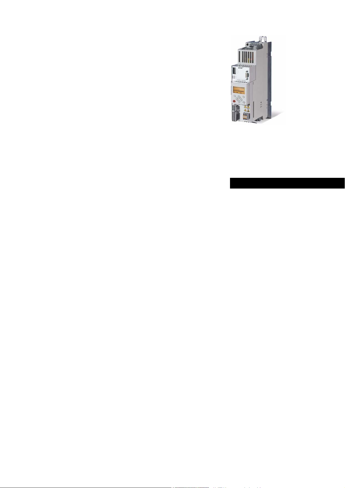
Danger!
The controller is a source of danger which may lead to death or severe injury of persons.
To protect yourself and others against these dangers, observe the safety instructions
before switching on the controller.
Please read the safety instructions provided in the 8400 mounting instructions and in
the 8400 hardware manual. Both documents are supplied with the controller.
Target group
This documentation addresses to all persons who would like to parameterise, configure and
diagnose the 8400 StateLine with the Lenze engineering software »Engineer« and the X400 keypad.
Validity
The information in this documentation are valid for the following standard devices:
Product series Type designation from software version
8400 StateLine C E84AVSCxxxxx 01.00
Screenshots/application examples
All screenshots provided in this documentation are application examples. Depending on the
software version of the controller and the version of the installed »Engineer« software, the
screenshots in this documentation may differ from the representation in the »Engineer«.
Tip!
Information and tools for Lenze products are provided in the download area at
http://www.lenze.com
1.1 Document history
Version Description
12.0 06/2014 TD05 Extended by new functions for 8400 StateLine C V15.00.00
11.0 11/2013 TD05 Extended by new functions for 8400 StateLine C V14.00.00
10.0 11/2012 TD05 Extended by new functions for 8400 StateLine C V13.00.00 and converted to
9.1 09/2012 TD05 Error corrections & supplements
9.0 08/2012 TD05 Extended by new functions for 8400 StateLine C V12.00.00
8.0 10/2011 TD05 Extended by new functions for 8400 StateLine C V11.00.00
7.1 02/2011 TD05 Error corrections & supplements
7.0 11/2010 TD05 Extended by new functions for 8400 StateLine C V06.00.00 and V10.00.00
Download
new layout.
Lenze · 8400 StateLine · Reference manual · DMS 12.0 EN · 06/2014 · TD05/TD14 15
Page 16
1 About this documentation
1.2 Conventions used
_ _ _ _ _ _ _ _ _ _ _ _ _ _ _ _ _ _ _ _ _ _ _ _ _ _ _ _ _ _ _ _ _ _ _ _ _ _ _ _ _ _ _ _ _ _ _ _ _ _ _ _ _ _ _ _ _ _ _ _ _ _ _ _
1.2 Conventions used
This documentation uses the following conventions to distinguish between different types of
information:
Type of information Writing Examples/notes
Spelling of numbers
Decimal separator Point The decimal point is generally used.
Example: 1234.56
Hexadecimal number 0x For hexadecimal numbers, the "0x" prefix is used.
Example: 0x60F4
Binary number 0b For binary numbers, the "0b" prefix is used.
Example: 0b00010111
Text
Version info Blue text colour All information that only applies to a certain controller
Program name » « The Lenze »Engineer« PC software ...
Window italics The Message window ... / The Options dialog box...
Variable identifier By setting bEnable to TRUE...
Control element bold The OK button... / The Copy command... / The Properties
Sequence of menu
commands
Shortcut <bold> Press <F1> to open the online help.
Hyperlink Underlined
Icons
Page reference ( 16) Optically highlighted reference to another page. In this
Step-by-step instructions
software version or higher is identified accordingly in this
documentation.
Example: This function extension is available from software
version V3.0!
tab... / The Name input field...
If the execution of a function requires several commands,
the individual commands are separated by an arrow: Select
Open to...
File
If a command requires a combination of keys, a "+" is placed
between the key symbols:
Use <Shift>+<ESC> to...
Optically highlighted reference to another topic. In this
documentation activated by mouse-click.
documentation activated by mouse-click.
Step-by-step instructions are indicated by a pictograph.
16
All information that only applies to a certain controller software version or higher is identified
accordingly in this documentation.
Lenze · 8400 StateLine · Reference manual · DMS 12.0 EN · 06/2014 · TD05/TD14
Page 17
1 About this documentation
1.3 Terminology used
_ _ _ _ _ _ _ _ _ _ _ _ _ _ _ _ _ _ _ _ _ _ _ _ _ _ _ _ _ _ _ _ _ _ _ _ _ _ _ _ _ _ _ _ _ _ _ _ _ _ _ _ _ _ _ _ _ _ _ _ _ _ _ _
1.3 Terminology used
Term Meaning
Engineering Tools Software solutions for simple engineering at all stages
»EASY Navigator« – Ensures easy operator guidance
• All practical Lenze engineering tools at a glance
• Tools can be selected quickly
• Clearly arranged, simplifying the engineering process from the start
»EASY Starter« – Simple tool for service technicians
• Especially developed for the commissioning and maintenance of Lenze
devices
• Graphical user interface with few buttons
• Simple online diagnostics, parameterisation and commissioning
• No risk of accidentally changing the application
• Ready applications can be loaded to the device
»Engineer« – Multi-device engineering
• For all products from our L-force portfolio
• Practice-oriented user interface
• Easy handling due to graphical user interfaces
• Suitable for all project stages (configuration, commissioning, production)
• Parameter setting and configuration
Application block Block for a technology application (e.g. actuating drive speed)
A technology application is a drive solution based on the experience and know-how of Lenze
in which function blocks interconnected to a signal flow form the basis for implementing
typical drive tasks.
ASM Abbreviation for asynchronous motor
CAN Abbreviation for Controller Area Network. CAN is an asynchronous, serial fieldbus system.
CANopen® is a communication protocol based on CAN. The Lenze system bus (CAN on board)
operates with a subset of this communication protocol.
CANopen® is a registered community trademark of the CAN user organisation CiA® (CAN in
Automation e. V.).
System bus "CAN on board"
Code Parameter used for controller parameterisation or monitoring.
The term is usually called "index".
Display code Parameter that displays the current status or value of an input/output of a system block.
Emergency brake The emergency brake serves to shutdown rotary or translatory masses in motion in
emergency situations. Emergency situations are exceptional situations that only occur
sporadically.
EtherCAT® is a real-time capable Ethernet system with maximum performanc.
EtherCAT® is a registered trademark and patented technology, licensed by the Beckhoff
Automation GmbH, Germany.
Ethernet POWERLINK is a real-time capable fieldbus system based on Ethernet. For user data
exchange, Ethernet POWERLINK specifies a communication protocol based on CANopen.
Ethernet POWERLINK is a patented technology licensed by the Ethernet POWERLINK
Standardization Group (EPSG), Germany.
EtherNet/IP™ (EtherNet Industrial Protocol) is a fieldbus system based on Ethernet which
uses the Common Industrial Protocol™ (CIP™) for data exchange.
EtherNet/IP™ and Common Industrial Protocol™ (CIP™) are trademarks and patented
technologies licensed by the user organisation ODVA (Open DeviceNet Vendor Association),
USA.
FB Editor Abbreviation for function block editor. Graphic interconnection tool which is available in the
»Engineer« for function block interconnections on the FB Editor.
Working with the FB Editor
Lenze · 8400 StateLine · Reference manual · DMS 12.0 EN · 06/2014 · TD05/TD14 17
Page 18
1 About this documentation
1.3 Terminology used
_ _ _ _ _ _ _ _ _ _ _ _ _ _ _ _ _ _ _ _ _ _ _ _ _ _ _ _ _ _ _ _ _ _ _ _ _ _ _ _ _ _ _ _ _ _ _ _ _ _ _ _ _ _ _ _ _ _ _ _ _ _ _ _
Term Meaning
Function block General designation of a function block for free interconnection in the FB Editor.
A function block (short: FB) can be compared with an integrated circuit that contains a
specific control logic and delivers one or several values when being executed. Example:
"L_Arithmetik_1" (FB for arithmetic operations)
Many function block are available several times (e.g. L_And_1, L_And_2 and L_And_3).
Function blocks
Holding brake The holding brake serves to statically hold e.g. a position during the downtimes of a
robot/travelling/synchronous/hoist drive.
INTERBUS was developed as sensor/actuator/bus system for transmitting process data.
Today, maintenance activities for the INTERBUS technologies are carried out by the user
organisation PROFIBUS & PROFINET International (PI).
Keypad The keypad is an alternative to the PC for the local operation, parameterisation, and
LA Abbreviation for Lenze Application block
Lenze setting This setting is the default factory setting of the device.
LP Abbreviation for Lenze Port block
LS Abbreviation for Lenze System block
MCI Abbreviation for Motionbus Communication Interface (fieldbus interface)
Port block Block for implementing the process data transfer via a fieldbus
PSM Abbreviation for permanently excited synchronous motor
QSP Abbreviation for quick stop
SC Abbreviation for Servo Control
Service brake The service brake serves to shutdown rotary or translatory masses in motion in a controlled
SLPSM Abbreviation for sensorless control of synchronous motors
SLVC Abbreviation for SensorLess Vector Control
Subcode If a code contains several parameters, these are stored in "subcodes".
System block System blocks provide interfaces to basic functions, to "free codes" and to the hardware of
USB diagnostic
adapter
VFCplus Abbreviation for Voltage Frequency Control
diagnostics in a simple manner.
Example: "LA_NCtrl" (block for the "Actuating drive speed" application)
Example: "LP_CanIn1" (CAN1 port block)
Example: "LS_DigitalInput" (system block for digital input signals)
The Inverter Drives 8400 can accommodate plug-in communication modules and can
therefore take part in the data transfer of an existing fieldbus system.
Fieldbus interface (MCI)
PROFIBUS® (Process Field Bus) is fieldbus system used worldwide for automating machines
and production plants.
PROFIBUS® is a registered trademark and patented technology licensed by the user
organisation PROFIBUS & PROFINET International (PI).
PROFINET® (Process Field Network) is a real-time capable fieldbus system based on Ethernet.
PROFINET® is a registered trademark and patented technology licensed by the user
organisation PROFIBUS & PROFINET International (PI).
manner. The energy to be dissipated in this process is produced in the form of friction
energy. Unlike emergency braking, this process is a regular and recurring operating mode.
This Manual uses a slash "/" as a separator between code and subcode (e.g. "C00118/3").
The term is usually called "subindex".
the controller in the FB editor of the »Engineer« (e.g. to the digital inputs). Each system block
is only available once.
System blocks
The USB diagnostic adapter is used for the operation, parameterisation, and diagnostics of
the controller. Data are exchanged between the PC (USB connection) and the controller
(diagnostic interface on the front) via the diagnostic adapter. Order designation: E94AZCUS
18
Lenze · 8400 StateLine · Reference manual · DMS 12.0 EN · 06/2014 · TD05/TD14
Page 19

1 About this documentation
1.4 Definition of the notes used
_ _ _ _ _ _ _ _ _ _ _ _ _ _ _ _ _ _ _ _ _ _ _ _ _ _ _ _ _ _ _ _ _ _ _ _ _ _ _ _ _ _ _ _ _ _ _ _ _ _ _ _ _ _ _ _ _ _ _ _ _ _ _ _
1.4 Definition of the notes used
The following signal words and symbols are used in this documentation to indicate dangers and
important information:
Safety instructions
Layout of the safety instructions:
Pictograph and signal word!
(characterise the type and severity of danger)
Note
(describes the danger and gives information about how to prevent dangerous
situations)
Pictograph Signal word Meaning
Danger! Danger of personal injury through dangerous electrical voltage
Danger! Danger of personal injury through a general source of danger
Stop! Danger of property damage
Application notes
Pictograph Signal word Meaning
Note! Important note to ensure trouble-free operation
Reference to a n imm inen t dan ger t hat m ay result in death or seri ous p erso nal injury
if the corresponding measures are not taken.
Reference to a n imm inen t dan ger t hat m ay result in death or seri ous p erso nal injury
if the corresponding measures are not taken.
Reference to a possible danger that may result in property damage if the
corresponding measures are not taken.
Tip! Useful tip for easy handling
Lenze · 8400 StateLine · Reference manual · DMS 12.0 EN · 06/2014 · TD05/TD14 19
Page 20

2 Introduction: Parameterising the controller
_ _ _ _ _ _ _ _ _ _ _ _ _ _ _ _ _ _ _ _ _ _ _ _ _ _ _ _ _ _ _ _ _ _ _ _ _ _ _ _ _ _ _ _ _ _ _ _ _ _ _ _ _ _ _ _ _ _ _ _ _ _ _ _
2 Introduction: Parameterising the controller
Being a component of a machine which includes a speed-variable drive system, the controller needs
to be adjusted to its drive task. The controller is adjusted by changing parameters which are saved
in the memory module. The parameters can be accessed by keypad, by the »EASY Starter« or by the
»Engineer«. Access is also possible by a master control via fieldbus communication. For this purpose,
the "CAN on board" CAN interface and the MCI interface for using a communication module (e.g.
PROFIBUS) are available.
Danger!
In general, changing a parameter causes an immediate response in the controller!
An enabled controller can cause an unwanted behaviour at the motor shaft! For
instance, setpoint sources can change over abruptly (e.g. when the signal source is
configured for the main setpoint).
Certain device commands or settings which may cause critical states of drive behaviour
constitute exceptions. Such parameter changes are only possible if the controller is
inhibited. Otherwise, a corresponding error message will be issued.
20 Lenze · 8400 StateLine · Reference manual · DMS 12.0 EN · 06/2014 · TD05/TD14
Page 21
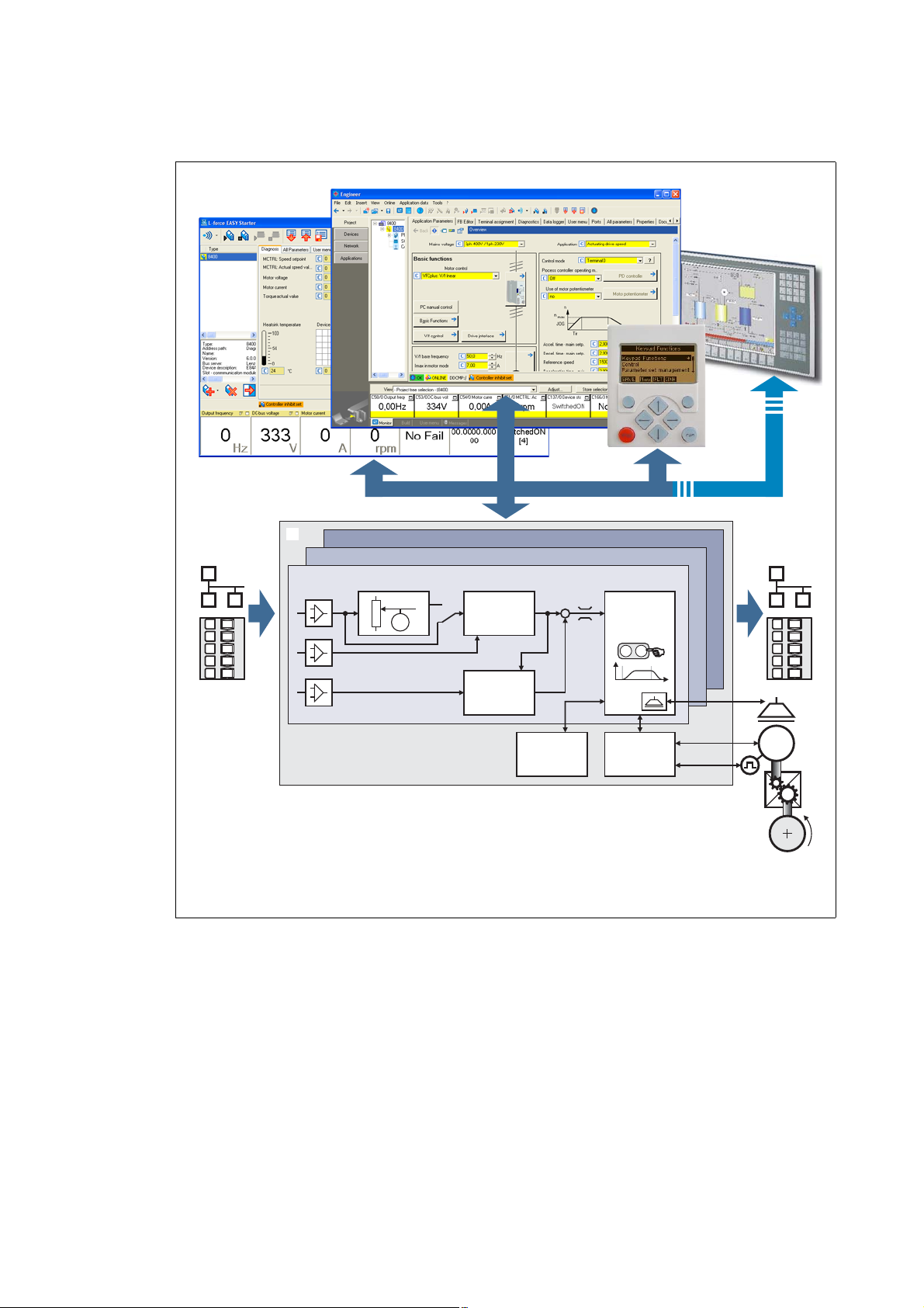
2 Introduction: Parameterising the controller
M
...
M
n
t
è
ç
02
1
Switch-off positioning
Actuating drive speed
Setpoint
generator
Process
controller
Motion
Control
Kernel
Device
control
Motor
control
Signal
inputs
Signal
outputs
Parameterisation
Fieldbus
L-force EASY Starter
L-force Engineer
Keypad
_ _ _ _ _ _ _ _ _ _ _ _ _ _ _ _ _ _ _ _ _ _ _ _ _ _ _ _ _ _ _ _ _ _ _ _ _ _ _ _ _ _ _ _ _ _ _ _ _ _ _ _ _ _ _ _ _ _ _ _ _ _ _ _
Signal inputs for control and setpoint signals
Signal flow of the integrated technology application (see the following subchapter)
Signal outputs for status and actual value signals
[2-1] Adaptation of the drive solution via parameter setting
Lenze · 8400 StateLine · Reference manual · DMS 12.0 EN · 06/2014 · TD05/TD14 21
Page 22
2 Introduction: Parameterising the controller
2.1 Integrated technology applications
_ _ _ _ _ _ _ _ _ _ _ _ _ _ _ _ _ _ _ _ _ _ _ _ _ _ _ _ _ _ _ _ _ _ _ _ _ _ _ _ _ _ _ _ _ _ _ _ _ _ _ _ _ _ _ _ _ _ _ _ _ _ _ _
2.1 Integrated technology applications
The following technology applications integrated in the drive controller 8400 StateLine provide the
main signal flow for the implementation of a general or a special drive solution:
Technology application "Actuating drive speed"
This preset technology application serves to solve speed-controlled drive tasks, e.g.
conveyor drives (interconnected), extruders, test benches, vibrators, travelling drives,
presses, machining systems, metering units.
technology application "Actuating drive speed (AC Drive Profile)"
This technology application available from version 13.00.00 provides a speed and
torque control by means of "AC Drive Profile". The fieldbuses EtherNet/IP™ and
system bus (CANopen) are supported.
"Switch-off positioning" technology application
This technology application available from version 04.00.00 is used to solve speedcontrolled drive tasks which require a pre-switch off or stopping at certain positions,
e.g. roller conveyors and conveying belts. The pre-switch off is implemented by
connecting switch-off sensors.
Note!
Please note that the "StateLine", "HighLine" and "TopLine" device types differ with regard
to the number, functional range, and flexibility of the technology applications offered.
Detailed information on each technology application can be found in the main chapter
"Technology applications
". ( 296)
22
Lenze · 8400 StateLine · Reference manual · DMS 12.0 EN · 06/2014 · TD05/TD14
Page 23

2 Introduction: Parameterising the controller
2.1 Integrated technology applications
_ _ _ _ _ _ _ _ _ _ _ _ _ _ _ _ _ _ _ _ _ _ _ _ _ _ _ _ _ _ _ _ _ _ _ _ _ _ _ _ _ _ _ _ _ _ _ _ _ _ _ _ _ _ _ _ _ _ _ _ _ _ _ _
2.1.1 Purpose of the technology applications
The stepped Inverter Drives 8400 series provides solutions for simple to complex applications –
depending on the user's experience and knowledge about the handling of drives and drive tasks.
On the one hand, a great scope of standard drive tasks for frequency inverters is covered by the
technology applications offered by Lenze, and on the other hand, the user is relieved from timeconsuming programming activities. In practice, some drive tasks are alike so that minor
modifications of the corresponding technology applications lead to quick results.
Other important features of technology applications are:
• Direct implementation of drive tasks without recreating a function block interconnection inside
the device
• Operation via keypad and/or operation via convenient operator dialogs in the «Engineer».
• Commissioning via few operating and diagnosing parameters (local keypad operation).
• Achieving a transparency as high as possible via the integrated functionality of the device by
representing signal flow diagrams.
• Provision of a basic functionality suitable and often sufficient for many applications.
2.1.2 Application cases for a technology application
You should use a technology application if
• the task can be solved completely or to a great extent by the basic functionality of the
technology application.
• the end customer does not want to create the comprehensive core functions of the
corresponding technology on his own.
• the creation time for a project is to be reduced by using the ready-made technology application
• the end customer wants to build upon the know-how of Lenze.
Tip!
If the end customer of the machine does not want to use ready-made Lenze functions, it is
also possible to implement individual drive solutions with the "StateLine C", "HighLine C"
and "TopLine C" versions in the form of "free interconnections". (In case of "StateLine C2,
free interconnection is only possible from version 12.00.00 and »Engineer« V2.17.)
Here, a technology application can be used as starting basis, which has to be adapted to the
requirement by a change or extension via function block editor (see the following chapter).
Lenze · 8400 StateLine · Reference manual · DMS 12.0 EN · 06/2014 · TD05/TD14 23
Page 24

2 Introduction: Parameterising the controller
2.1 Integrated technology applications
_ _ _ _ _ _ _ _ _ _ _ _ _ _ _ _ _ _ _ _ _ _ _ _ _ _ _ _ _ _ _ _ _ _ _ _ _ _ _ _ _ _ _ _ _ _ _ _ _ _ _ _ _ _ _ _ _ _ _ _ _ _ _ _
2.1.3 Technology application = function block interconnection
In case of the 8400 device version, each technology application is connected to a "function block
interconnection" ("FB interconnection"). This FB interconnections serve to implement signal
interconnections. Various FBs are available for digital signal processing, signal conversion and logic
modules.
For special drive tasks it has proved of value to use the integrated technology applications as a basis
for modifications or extensions of the available FB interconnections.
I/O level & application level
The interconnection of the interfaces is shown in the I/O level of the function block editor according
to the selected control mode. In the "deeper" application level, the main signal flow is realised in the
form of an interconnection of various function and system blocks.
For the device versions "StateLine C", "HighLine C" and "TopLine C" the following applies:
• The preconfigured signal links can be reconfigured in the I/O level if required.
• Moreover, applications integrated in the controller can be reconfigured in the application level
and extended by individual functions.
• Moreover, experienced users are offered the opportunity to implement their own drive
solutions independent of the predefined technology applications by using so-called "free
interconnections". (In case of "StateLine C", free interconnection is only possible from version
12.00.00 and »Engineer« V2.17.)
Motion Control Kernel
Important basic (drive) functions as well as further basic functionalities are implemented in the
firmware of the drive controller in the so-called Motion Control Kernel (MCK) which can be accessed
by the active technology application via defined internal interfaces. By this means the expensive
creation of single function block interconnections is omitted so that the expenditure and the
complexity for the realisation of standard functions is minimised.
The Motion Control Kernel is integrated in the main setpoint path and, depending on the set
operating mode, it creates the required control and setpoint signals for the motor control and the
drive interface.
More detailed information:
• A detailed description of the basic functions implemented in the Motion Control
Kernel can be found in the main chapter "Basic drive functions (MCK)
• Detailed information on the creation or change of interconnections by means of the
function block editor can be found in the main chapter "Working with the FB Editor
( 857)
• All available function and system blocks are described in the main chapter "Function
library". ( 909)
". ( 390)
".
24
Lenze · 8400 StateLine · Reference manual · DMS 12.0 EN · 06/2014 · TD05/TD14
Page 25
2 Introduction: Parameterising the controller
2.2 Selection of the appropriate commissioning tool
_ _ _ _ _ _ _ _ _ _ _ _ _ _ _ _ _ _ _ _ _ _ _ _ _ _ _ _ _ _ _ _ _ _ _ _ _ _ _ _ _ _ _ _ _ _ _ _ _ _ _ _ _ _ _ _ _ _ _ _ _ _ _ _
2.2 Selection of the appropriate commissioning tool
There are several possibilities for commissioning the 8400 StateLine controller:
Commissioning via keypad X400 (or diagnosis terminal X400)
The keypad is an alternative to the PC for the local operation, parameterisation, and
diagnostics in a simple manner. The keypad is especially suited for test and
demonstration purposes and for the case that only few parameters have to be
adapted.
Commissioning using PC and »EASY Starter«
The »EASY Starter« is a Lenze tool for simple online diagnostics, parameterisation and
commissioning of the controller.
Commissioning using PC and »Engineer«
The »Engineer« is a Lenze engineering software for parameter setting across all
devices, configuring and diagnosing individual components (as for instance
controllers, industrial PCs, motors, I/O systems) and machine control systems.
Tip!
The engineering tools »EASY Starter« and »Engineer StateLevel« are provided free of charge
in the internet:
http://www.lenze.com
For communication between PC and controller, the USB diagnostic adapter can be used for
instance (see the following subchapter).
Download Software Downloads
Lenze · 8400 StateLine · Reference manual · DMS 12.0 EN · 06/2014 · TD05/TD14 25
Page 26
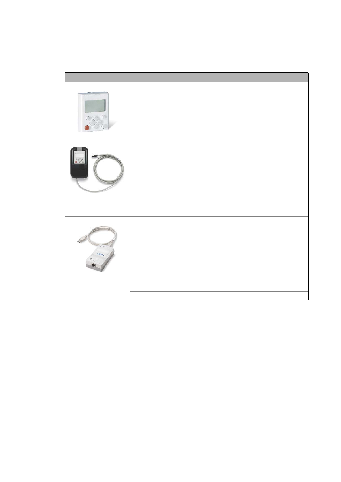
2 Introduction: Parameterising the controller
2.2 Selection of the appropriate commissioning tool
_ _ _ _ _ _ _ _ _ _ _ _ _ _ _ _ _ _ _ _ _ _ _ _ _ _ _ _ _ _ _ _ _ _ _ _ _ _ _ _ _ _ _ _ _ _ _ _ _ _ _ _ _ _ _ _ _ _ _ _ _ _ _ _
2.2.1 Overview: Accessories for commissioning
Version Features Product key
Keypad X400 Quick access to parameters and operating data
• Supports hot plugging
• Graphic display with plain texts
• Backlighting
• Easy user guidance
• 4 navigation keys, 2 context-sensitive keys
•Adjustable RUN/STOP function
• Can be used for L-force Inverter Drives 8400 and Servo
Drives 9400
Diagnosis terminal X400 Keypad X400 in a robust housing, also suitable for
USB diagnostic adapter For electrical isolation of your PC and the controller.
installation into the control cabinet door.
• Supports hot plugging
• Graphic display with plain texts
• Backlighting
• Easy user guidance
• 4 navigation keys, 2 context-sensitive keys
•Adjustable RUN/STOP function
• Incl. 2.5 m cable
• Enclosure IP20; in case of front installation in control
cabinet IP65
• Can be used for L-force Inverter Drives 8400 and Servo
Drives 9400
• Supports hot plugging
• Diagnostic LED for data transfer display
• plug and play
• Input-side voltage supply via USB connection from PC
• Output-side voltage supply via the diagnostic interface of
the controller
• Connecting cables can be selected in various lengths:
EZAEBK1001
EZAEBK2001
E94AZCUS
Connecting cable for
USB diagnostic adapter
2.5 m length EWL0070
5 m length EWL0071
10 m length EWL0072
26
Lenze · 8400 StateLine · Reference manual · DMS 12.0 EN · 06/2014 · TD05/TD14
Page 27

2 Introduction: Parameterising the controller
2.3 General notes on parameters
_ _ _ _ _ _ _ _ _ _ _ _ _ _ _ _ _ _ _ _ _ _ _ _ _ _ _ _ _ _ _ _ _ _ _ _ _ _ _ _ _ _ _ _ _ _ _ _ _ _ _ _ _ _ _ _ _ _ _ _ _ _ _ _
2.3 General notes on parameters
All parameters for controller parameterising or monitoring are saved as so-called "codes".
• The codes are numbered and indicated by the prefix "C" before the code, e.g. "C00002".
• Moreover, each code has a name and specific attributes, as for example access type (reading,
writing), data type, limit values and default setting ("Lenze setting").
• For the sake of clarity, some codes contain "subcodes" for saving parameters. This Manual uses
a slash "/" as a separator between code and subcode, e.g. C00118/3".
• According to their functionality, the parameters are divided into three groups:
• Setting parameters: For specifying setpoints and for setting device / monitoring functions.
• Configuration parameters: For configuring signal connections and terminal assignments.
• Diagnostic/display parameters: For displaying device-internal process factors, current actual
values and status messages. These are read-only parameters.
Lenze · 8400 StateLine · Reference manual · DMS 12.0 EN · 06/2014 · TD05/TD14 27
Page 28
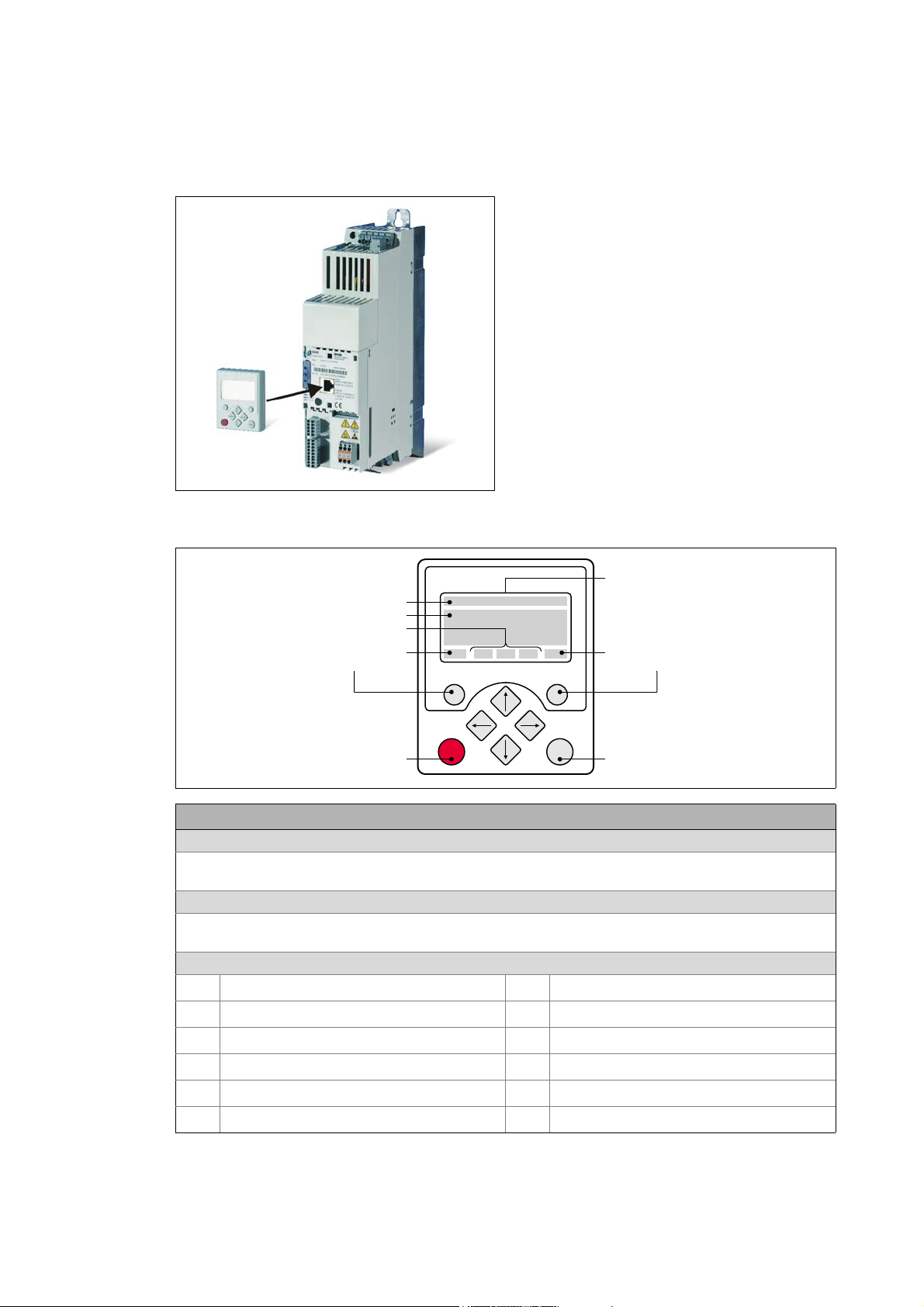
2 Introduction: Parameterising the controller
WXST VYR
+HDGOLQH
7ULSOHOLQHGLVSOD\
&XUUHQWIXQFWLRQ
ULJKWIXQFWLRQNH\
&XUUHQWIXQFWLRQ
OHIWIXQFWLRQNH\
/&'GLVSOD\
'HYLFHVWDWH
,QPDQXDOFRQWUROPRGH
6WDUWPRWRU
,QPDQXDOFRQWUROPRGH
6WRSPRWRU
2.3 General notes on parameters
_ _ _ _ _ _ _ _ _ _ _ _ _ _ _ _ _ _ _ _ _ _ _ _ _ _ _ _ _ _ _ _ _ _ _ _ _ _ _ _ _ _ _ _ _ _ _ _ _ _ _ _ _ _ _ _ _ _ _ _ _ _ _ _
2.3.1 Changing the parameterisation with the keypad
The keypad is simply plugged on the diagnostic
interface X6 ("DIAG") at the front of the standard
device.
Plugging and unplugging the keypad is possible
during operation.
Keypad display and control elements
LCD display
Headline
In the menu level: Menu name
In the parameter level: Parameter name
Three-part display
In the menu level: List of available menus
In the parameter level: Code/subcode and setting or actual value
Device status
Controller is switched on
Controller is enabled
Controller is inhibited
Quick stop active
Current limit exceeded
Speed controller 1 in the limitation
Pulse inhibit active
System fault active
"Fault" device status is active
"Trouble" device status is active
"TroubleQSP" device status is active
A warning is indicated
28
Lenze · 8400 StateLine · Reference manual · DMS 12.0 EN · 06/2014 · TD05/TD14
Page 29
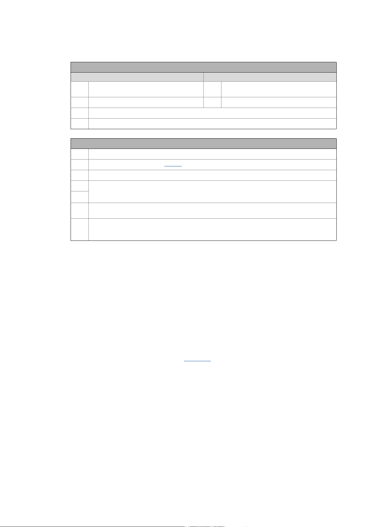
2 Introduction: Parameterising the controller
2.3 General notes on parameters
_ _ _ _ _ _ _ _ _ _ _ _ _ _ _ _ _ _ _ _ _ _ _ _ _ _ _ _ _ _ _ _ _ _ _ _ _ _ _ _ _ _ _ _ _ _ _ _ _ _ _ _ _ _ _ _ _ _ _ _ _ _ _ _
LCD display
Function - left function key Function - right function key
Change parameter setting
(change to editing mode)
Back to main menu
Parameter can only be changed when the controller is inhibited
Save all parameter settings in the memory module safe against mains failure
Control elements
Execute the function assigned to the function key (see LCD display)
Execute the stop function set in C00469 (Lenze setting: Inhibit controller)
Deactivate stop function again (Lenze setting: Enable controller again)
In the menu level: Select menu/submenu
In the parameter level: Select parameter
In the editing mode: Change marked digits or select list entry
In the menu level: Select submenu/change to parameter level
In the editing mode: Cursor to the right
In the menu level: One menu level higher (if available)
In the parameter level: Back to the menu level
In the editing mode: Cursor to the left
Accept change in the controller
(no saving with mains failure protection
Abort (discard change)
)
Menu structure
In the keypad, the parameters are classified into various menus and submenus.
•The USER menu includes a selection of frequently used parameters.
•The Code list contains all parameters.
•The Go to param function enables you to reach the corresponding parameter directly.
•The Logbook logs all errors and their chronological history.
•The Diagnostics menu contains diagnostic/display parameters for displaying device-internal
process factors, current actual values and status messages.
Userlevel
From version 12.00.00 onwards, the extent of menus, submenus an codes shown in the keypad can
be adapted by selecting the "Userlevel" in C00001/1
:
• Userlevel Standard (Lenze setting): Only the most important menus and codes are shown in the
keypad.
• Userlevel Expert: All menus and codes are shown in the keypad.
• Userlevel Service: For service purposes only (Lenze service).
The the Userlevel has been changed, the menus are restructured in the keypad according to the
selected Userlevel. The parameters of a plugged in communication module are always displayed
completely independent of the set Userlevel.
Lenze · 8400 StateLine · Reference manual · DMS 12.0 EN · 06/2014 · TD05/TD14 29
Page 30
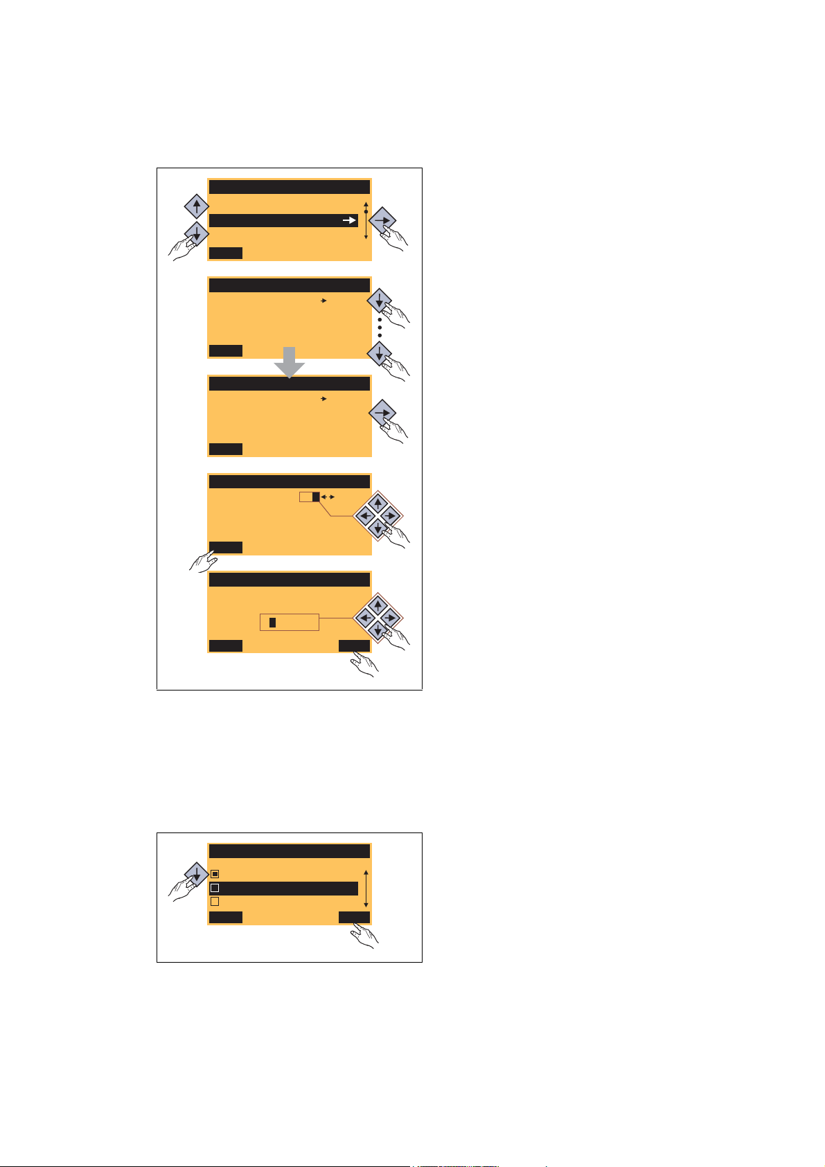
2 Introduction: Parameterising the controller
Load Lenze setting
C00002/001
Off / Finished
EDIT
Par1 8400 StateLine C
SAVE
Code list
Go To Param
USER - Menu
Fixed setpoint 1
C00039/001
40.00 %
EDIT
Fixed setpoint 2
60.00 %
EDIT
C00039/002
Fixed setpoint 2
C00039/002
ESC
60.00 %
OK
1.
2.
3.
5.
4.
6.
Language
ESC
Français
Deutsch
English
OK
2.3 General notes on parameters
_ _ _ _ _ _ _ _ _ _ _ _ _ _ _ _ _ _ _ _ _ _ _ _ _ _ _ _ _ _ _ _ _ _ _ _ _ _ _ _ _ _ _ _ _ _ _ _ _ _ _ _ _ _ _ _ _ _ _ _ _ _ _ _
General operation
1. Use the / navigation keys to select the
desired menu.
•Use the / navigation keys to reach a
higher/lower menu level.
•Use the function key to return to the
main menu.
2. Use the / navigation keys to select the
parameter to be set within a submenu.
3. In order to select another subcode in case of a
parameter with subcodes:
• Press the navigation key to change tot he
editing mode for the subcode.
• Use the navigation keys to set the desired
subcode.
4. Use the function key to switch over to the
editing mode.
[2-2] Example: Changing parameters with the keypad
5. Use the navigation keys to set the desired value.
6. Use the function key to accept the change
and to leave the editing mode.
•Use the function key to leave the editing
mode without accepting the change.
Multilingualism
All texts displayed in the keypad are in English.
From version 11.00.00 onwards, the most important menus as well as diagnostic and configuration
parameters can are also available in German and French. To set a different language, select the
Language selection menu item in the main menu of the keypad.
• The multilingual texts are stored in the
controller and do not have to be loaded into the
device.
• For reasons of disc space, only the most
important menus and parameters as well as the
error messages are available in several
languages.
30
Lenze · 8400 StateLine · Reference manual · DMS 12.0 EN · 06/2014 · TD05/TD14
Page 31

2 Introduction: Parameterising the controller
2.3 General notes on parameters
_ _ _ _ _ _ _ _ _ _ _ _ _ _ _ _ _ _ _ _ _ _ _ _ _ _ _ _ _ _ _ _ _ _ _ _ _ _ _ _ _ _ _ _ _ _ _ _ _ _ _ _ _ _ _ _ _ _ _ _ _ _ _ _
2.3.2 Change parameter settings with PC and Lenze software
The USB diagnostic adapter, for instance, can be used for the communication between the PC
(including the »Engineer« software) and the controller, see the following illustration. The USB
diagnostic adapter is the connection between the PC (free USB port) and the controller (X6
diagnostic interface).
[2-3] Exemplary constellation for parameterising the controller
The All parameters tab in the »EASY Starter« and the »Engineer« provides a quick access to all
parameters of the controller.
The given categories and subcategories correspond 1:1 to the menus and submenus of the keypad:
Category
Subcategories
[2-4] All parameters tab in the »Engineer«
Moreover, the »Engineer« provides a commissioning interface on the Application parameters tab
where you can commission the application in a few steps.
Detailed information on how to handle the »Engineer« can be found in the integrated
online help that you can call with the [F1] function key.
Lenze · 8400 StateLine · Reference manual · DMS 12.0 EN · 06/2014 · TD05/TD14 31
Page 32

2 Introduction: Parameterising the controller
2.3 General notes on parameters
_ _ _ _ _ _ _ _ _ _ _ _ _ _ _ _ _ _ _ _ _ _ _ _ _ _ _ _ _ _ _ _ _ _ _ _ _ _ _ _ _ _ _ _ _ _ _ _ _ _ _ _ _ _ _ _ _ _ _ _ _ _ _ _
2.3.3 Save parameter settings in the memory module safe against mains failure
Controller parameter changes via the EASY Starter /»Engineer«, the keypad, or a master control via
fieldbus communication will be lost after mains switching of the controller unless the settings have
been explicitly saved to the integrated memory module.
General information
• In the delivery state, the Lenze setting of the parameters has been saved to the integrated
memory module. These parameters are
• the parameters of the controller
• the parameters of the communication module plugged into the MCI interface
• the parameters of the possibly existing safety module (device variant)
• When the device or the external 24 V voltage supply is switched on, all parameters are
automatically loaded from the memory module into the main memory of the controller.
• Full functionality of the memory module is even provided if the power supply has been switched
off and only the electronic components of the controller are externally supplied by a 24 V DC
voltage, e.g. via the X4/24E terminal.
• The memory module can be preconfigured with customised data.
• The memory module is available as a spare part - without any data.
During operation
• Parameter sets can be saved and loaded manually.
• Using the keypad, you can press function key
• The »EASY Starter«/»Engineer« serves to execute the saving via the icon in the toolbar or via
the device command "Save all parameter sets" (C00002/11
• The storage process may take a couple of seconds. After the device command has been called
in C00002/11
40%" "Work in progress 60%", etc.) is returned.
, dynamic status information ("Work in progress 20%" "Work in progress
to save the parameter settings.
="1:On / start").
Note!
In order to prevent data inconsistencies during the saving process:
• Do not switch off the supply voltage!
• Do not remove the memory module from the device!
Automatic saving of changed parameter settings is explicitly not supported because this
significantly reduces the service life of the memory module.
32
Lenze · 8400 StateLine · Reference manual · DMS 12.0 EN · 06/2014 · TD05/TD14
Page 33

2 Introduction: Parameterising the controller
Version
x.x
Version
x.x³
StateLine HighLine
TopLine
2.3 General notes on parameters
_ _ _ _ _ _ _ _ _ _ _ _ _ _ _ _ _ _ _ _ _ _ _ _ _ _ _ _ _ _ _ _ _ _ _ _ _ _ _ _ _ _ _ _ _ _ _ _ _ _ _ _ _ _ _ _ _ _ _ _ _ _ _ _
Unplugging the memory module
The memory module is hot-pluggable. A removal during operation causes a warning "PS01: No
memory module" and should thus be avoided. The behaviour of the device, however, remains
unchanged as all parameters are available in the RAM memory after the device has been started.
The device can also be parameterised when the memory module has been unplugged. In this case,
the parameter sets cannot be saved in the memory module.
Replacing the controller
In the event of a device replacement, the entire parameter data of an axis can be copied to the
replacement device by "taking along" the memory module, so that additional PC or keypad
operations are not required.
When replacing the controller, the versions of the old device and the new device are of importance.
Before data are actually transferred, the versions are internally checked. Basically, the following
applies:
• Parameter sets of old devices can only be
processed on new devices with the same or
higher device version (downward compatibility).
• Parameter sets of devices with versions that have
less functions (e.g. 8400 StateLine) can be loaded
into and executed on devices with versions that
have more functions (e.g. 8400 HighLine). The
reverse is not possible!
• If the parameter set saved in the memory module
is not compatible with the standard device, the
"PS03: Par.set device invalid
" is output.
Lenze · 8400 StateLine · Reference manual · DMS 12.0 EN · 06/2014 · TD05/TD14 33
Page 34

2 Introduction: Parameterising the controller
2.3 General notes on parameters
_ _ _ _ _ _ _ _ _ _ _ _ _ _ _ _ _ _ _ _ _ _ _ _ _ _ _ _ _ _ _ _ _ _ _ _ _ _ _ _ _ _ _ _ _ _ _ _ _ _ _ _ _ _ _ _ _ _ _ _ _ _ _ _
2.3.4 User menu for quick access to frequently used parameters
When a system is installed, parameters must be changed time and again until the system runs
satisfactorily. The user menu of the controller contains a selection of frequently used parameters to
be able to access and change these parameters quickly:
Parameter Name Lenze setting
C00051 MCTRL: Actual speed value -
C00053 DC-bus voltage -
C00054 Motor current -
C00061 Heatsink temperature -
C00137 Device status -
C00166/3 Mess. - status det. error -
C00011 Appl.: Reference speed 1500 rpm
C00039/1
C00039/2
C00012 Acceleration time - main setpoint 2.000 s
C00013
C00015
C00016
C00022
C00120
C00087
C00099 Firmware version -
C00200 Firmware product type -
C00105
C00173
Highlighted in grey = display parameter
Fixed setpoint 1 40.00 %
Fixed setpoint 2 60.00 %
Deceleration time - main setpoint 2.000 s
VFC: V/f base frequency 50 Hz
VFC: Vmin boost 1.60 %
Imax in motor mode depending on the device power
Setting of motor overload (I2xt) 100.00 %
Rated motor speed 1460 rpm
Decel. time - quick stop 2.000 s
Mains voltage 0: "3ph 400V / 1ph 230V"
34
Tip!
The user menu can be freely configured in C00517
In the »Engineer«, you can configure the user menu comfortably via the User menu tab (see
»Engineer« online help).
The password protection
serves to restrict the access to parameters of the user menu. Then,
all other parameters cannot be accessed without knowing the password and are thus
protected against unwanted changes.
Lenze · 8400 StateLine · Reference manual · DMS 12.0 EN · 06/2014 · TD05/TD14
.
Page 35

2 Introduction: Parameterising the controller
2.4 Device access protection
_ _ _ _ _ _ _ _ _ _ _ _ _ _ _ _ _ _ _ _ _ _ _ _ _ _ _ _ _ _ _ _ _ _ _ _ _ _ _ _ _ _ _ _ _ _ _ _ _ _ _ _ _ _ _ _ _ _ _ _ _ _ _ _
2.4 Device access protection
This function extension is available from version 06.00.00!
Various tasks can be executed via the functions of the device access protection:
• Password protection
• Only authorised persons (with password knowledge) may read/change all parameters of the
controller.
• Non-authorised persons (without password knowledge) can only access the max. 32
parameters of the user menu.
• Device personalisation
• Only controller personalised with a specific binding ID and memory modules can be used in
the system.
Note!
If password protection/device personalisation is used:
• Inform the end customer that Lenze can only provide restricted service for the devices
with access protection.
• It is not possible for Lenze to modify a replacement device via special accesses in such
a way that it cooperates with a personalised memory module.
• The keypad does not support the alpha-numeric entry of a password, thus the keypad
cannot be used for entry.
Lenze · 8400 StateLine · Reference manual · DMS 12.0 EN · 06/2014 · TD05/TD14 35
Page 36

2 Introduction: Parameterising the controller
2.4 Device access protection
_ _ _ _ _ _ _ _ _ _ _ _ _ _ _ _ _ _ _ _ _ _ _ _ _ _ _ _ _ _ _ _ _ _ _ _ _ _ _ _ _ _ _ _ _ _ _ _ _ _ _ _ _ _ _ _ _ _ _ _ _ _ _ _
2.4.1 Password protection
When the password protection is active, only write/read access to the parameters of the user menu
is possible.
• From version 15.00.00, the password protection can be configured individually for every single
communication channel. Individual password protection for single communication channels
( 38)
• The following describes how to set/check/delete a password by means of the parameters
relevant for these functions.
• From »Engineer« V2.14 onwards. these functions can also be executed via dialog (menu
command Online Set/check/delete password).
Note!
The password protection serves to only limit the access to parameters of the standard
device. The access to parameters of a plugged-in communication module is not
concerned.
Short overview of the relevant parameters for password protection:
Parameter Info Lenze setting
C00505/3
Device commands
Before
the following device commands are executed, enter the corresponding password in C00505/3.
C00002/31
C00002/32
C00002/33
Highlighted in grey = display parameter
Password
• The password must have a length of 4 ... 16 characters.
• The password may consist of any character. However, this is not
sensible. Recommended characters are: lower case letters (a - z),
upper case letters (A - Z) and digits (0 - 9).
Note:
After the execution
parameter returns the current password status:
off No password is set, password protection is not active
Set password
Activate the password protection
Check password
Temporarily deactivate the password protection
Delete password
Deactivate password protection/change password
of one of t he de vic e com man ds list ed belo w, this
(Lenze delivery status).
on Password is set, password protection is active.
• This status is also displayed if checking/deleting
the password has not been successful due to an
invalid entry.
ok Password is set, password protection is not active.
• The password protection is temporarily
deactivated.
0: Off / ready
0: Off / ready
0: Off / ready
36
Lenze · 8400 StateLine · Reference manual · DMS 12.0 EN · 06/2014 · TD05/TD14
Page 37

2 Introduction: Parameterising the controller
2.4 Device access protection
_ _ _ _ _ _ _ _ _ _ _ _ _ _ _ _ _ _ _ _ _ _ _ _ _ _ _ _ _ _ _ _ _ _ _ _ _ _ _ _ _ _ _ _ _ _ _ _ _ _ _ _ _ _ _ _ _ _ _ _ _ _ _ _
Parameter Info Lenze setting
Status displays
C00003 Status of the last device command -
C00507/1 Password protection - all communication channels
• Bit coded display of the active protective functions:
Bit 0 Only access to user menu
Bit 1 Parameter write protection
Bit 2 Parameter read protection
Bit 3 ... 14 Reserved
Bit 15 Memory module binding on
Note:
As the password protection can be configured individually for each
single communication channel from version 15.00.00 bit 1 and bit 2
indicate the active protection always with regard to the
communication channel used
Highlighted in grey = display parameter
.
-
Activate the password protection
The password protection is activated by setting a password.
How to set a password:
1. Enter the desired password in C00505/3
• The password must have a length of 4 ... 16 characters.
• The password may consist of any character. However, this is not sensible.
Recommended characters are: lower case letters (a - z), upper case letters (A - Z) and
digits (0 - 9).
2. Execute "Set password" device command: C00002/31
• After successful execution, password status ON is displayed in C00505/3
protection takes immediate effect.
Temporarily deactivate the password protection
The "Check password" device command serves to temporarily deactivate the password protection
in order to execute password-protected functions.
• The password protection remains deactivated until
• an invalid password will be entered and checked
- or -
• the external 24-V supply of the control electronics is switched off (< 19 V).
.
="1:On / start"
and password
How to temporarily deactivate the active password protection:
1. Enter the set password in C00505/3
2. Execute "Check password" device command C00002/32
• After a successful check, password status OK is displayed in C00505/3
Lenze · 8400 StateLine · Reference manual · DMS 12.0 EN · 06/2014 · TD05/TD14 37
.
= "1: On / start"
.
Page 38

2 Introduction: Parameterising the controller
2.4 Device access protection
_ _ _ _ _ _ _ _ _ _ _ _ _ _ _ _ _ _ _ _ _ _ _ _ _ _ _ _ _ _ _ _ _ _ _ _ _ _ _ _ _ _ _ _ _ _ _ _ _ _ _ _ _ _ _ _ _ _ _ _ _ _ _ _
Deactivate password protection/change password
The password protection is simply activated by deleting the set password. If you want to change the
set password, first delete the set password as well. Then set the new password.
How to delete the set password:
1. Enter the set password in C00505/3
2. Execute "Delete password" device command C00002/33
• After a successful deletion, password status OFF is displayed in C00505/3
.
= "1: On / start"
2.4.2 Individual password protection for single communication channels
This function extension is available from version 15.00.00!
The 8400 StateLine can be parameterised via the following "communication channels":
• Internally via system blocks (LS_ParReadWrite1-6
•externally via
•Diagnostics interface X6 ("DIAG")
• CANopen interface X1 ("CAN on board")
• Fieldbus interface (MCI)
As in some applications, only certain communication channels have to be protected, the parameters
described in the following serve to configure individual access restrictions for each communication
channel.
and LS_WriteParamList)
In the Lenze setting, all access restrictions are active for all communication channels when the
password is set. This corresponds to the previous behaviour with a set password, i.e. only one
write/read access to the parameters of the user menu is possible.
.
Note!
The configuration can only be changed if no password has been set!
• This means that even if the password has been deactivated temporarily by the "check
password" device command, the configuration cannot be changed.
• As long as a password is set, the "Load Lenze setting" device command does not
change the configuration either.
The password protection is activated by setting a password.
Activate the password protection
Deactivate password protection/change password
( 37)
( 38)
38
Lenze · 8400 StateLine · Reference manual · DMS 12.0 EN · 06/2014 · TD05/TD14
Page 39

2 Introduction: Parameterising the controller
2.4 Device access protection
_ _ _ _ _ _ _ _ _ _ _ _ _ _ _ _ _ _ _ _ _ _ _ _ _ _ _ _ _ _ _ _ _ _ _ _ _ _ _ _ _ _ _ _ _ _ _ _ _ _ _ _ _ _ _ _ _ _ _ _ _ _ _ _
Short overview of the relevant parameters for configuring the password protection:
When the password is set, the respective restriction is active if the corresponding bit has been set:
Parameter Info Lenze setting
C00506/1
C00508/1
C00509/1
C00510/1
PW protection internal config 0x0007
Bit 0 Only access to user menu
• The menus in the keypad are reduced.
• Only the user menu can be used to change
parameters.
Bit 1 Parameter write protection
• System blocks cannot be used to write into
write/read parameters.
Bit 2 Parameter read protection
• System blocks cannot be used to read write/read
parameters.
Bit 3 ... 15 Reserved
PW protection config. X6 (DIAG) 0x0006
Bit 0 Reserved
Bit 1 Parameter write protection
• The diagnostics interface X6 cannot be used to
write into write/read parameters.
Bit 2 Parameter read protection
• The diagnostics interface X6 cannot be used to
read write/read parameters.
Bit 3 ... 15 Reserved
PW protection config. X1 (CAN) 0x0006
Bit 0 Reserved
Bit 1 Parameter write protection
• The CANopen interface X1 cannot be used to
write into write/read parameters.
Bit 2 Parameter read protection
• T he CA Nope n interface X1 ca nnot be us ed to read
write/read parameters.
Bit 3 ... 15 Reserved
PW protection config. MCI 0x0006
Bit 0 Reserved
Bit 1 Parameter write protection
• The fieldbus interface (MCI) cannot be used to
write into write/read parameters.
Bit 2 Parameter read protection
• The fieldbus interface (MCI) cannot be used to
read write/read parameters.
Bit 3 ... 15 Reserved
The parameter set must be saved to the device safe against mains failure to prevent password
protection configured in the device from getting lost due to mains switching.
Save parameter settings in the memory module safe against mains failure
Lenze · 8400 StateLine · Reference manual · DMS 12.0 EN · 06/2014 · TD05/TD14 39
( 32)
Page 40

2 Introduction: Parameterising the controller
------
ABCABC
---ABC
ABC123
2.4 Device access protection
_ _ _ _ _ _ _ _ _ _ _ _ _ _ _ _ _ _ _ _ _ _ _ _ _ _ _ _ _ _ _ _ _ _ _ _ _ _ _ _ _ _ _ _ _ _ _ _ _ _ _ _ _ _ _ _ _ _ _ _ _ _ _ _
2.4.3 Device personalisation
The controller and the memory module are married via the device personalisation by means of a
binding ID. When the device personalisation is active, all write/read actions between controller and
memory module are only executed if both components have the same binding ID.
Lenze delivery status: Procedure carried out by the
customer:
No binding ID is set. Customer sets binding ID for device
personalisation.
Impermissible replacement by the
end user:
When device personalisation is
active:
The replacement of the controller or
memory module causes an error
message if the binding ID is incorrect
or not available.
If, for instance, a parameter set has been loaded from the memory module with an active device
personalisation, saving of this parameter set on another memory module with a different or nonexistent binding ID is not possible.
• Thus, copying the parameter set from a personalised memory module to a non-personalised
memory module is not possible!
Two types of checks are distinguished:
• If a differing binding ID is detected when the controller is switched on (during device
initialisation):
• the "Fault" error response is returned.
•The "PS10: Invalid memory module binding
" error message is entered into the logbook.
• If a differing binding ID is detected while a device command for loading/saving the parameter
set is executed:
• Loading/saving is not executed.
• A corresponding status for the device command is output in C00003
.
Short overview of the relevant parameters for device personalisation:
Parameter Info Lenze setting
C00505/2
Highlighted in grey = display parameter
40
Binding ID
• The binding ID must have a length of 4 ... 16 characters.
• The binding ID may consist of any character. However, this is not
sensible. Recommended characters are: lower case letters (a - z),
upper case letters (A - Z) and digits (0 - 9).
Note:
After the execution
parameter returns the current binding ID status:
off No binding ID is set.
of one of t he de vic e com man ds list ed belo w, this
on Binding ID is set.
Lenze · 8400 StateLine · Reference manual · DMS 12.0 EN · 06/2014 · TD05/TD14
Page 41

2 Introduction: Parameterising the controller
2.4 Device access protection
_ _ _ _ _ _ _ _ _ _ _ _ _ _ _ _ _ _ _ _ _ _ _ _ _ _ _ _ _ _ _ _ _ _ _ _ _ _ _ _ _ _ _ _ _ _ _ _ _ _ _ _ _ _ _ _ _ _ _ _ _ _ _ _
Parameter Info Lenze setting
Device commands
Before
the following device commands are executed, enter the corresponding binding ID in C00505/2.
C00002/29
C00002/30
Status displays
C00003 Status of the last device command -
C00507/1 Password protection - all communication channels
Highlighted in grey = display parameter
Set binding ID
Activate device personalisation
Delete binding ID
Deactivate device personalisation/change binding ID
• Bit coded display of the active protective functions:
Bit 0 Only access to user menu
Bit 1 Parameter write protection
Bit 2 Parameter read protection
Bit 3 ... 14 Reserved
Bit 16 Memory module binding on
0: Off / ready
0: Off / ready
-
Activate device personalisation
The device personalisation is activated by setting a binding ID.
How to set the binding ID:
1. Enter the desired binding ID in C00505/2
• The binding ID must have a length of 4 ... 16 characters.
• The binding ID may consist of any character. However, this is not sensible.
Recommended characters are: lower case letters (a - z), upper case letters (A - Z) and
digits (0 - 9).
2. Execute "Set binding ID" device command C00002/29
• After successful execution, status ON is displayed in C00505/2
Deactivate device personalisation/change binding ID
The device personalisation is simply deactivated by deleting the set binding ID. If you want to
change the set binding ID, first delete the set binding ID as well. Then set the new binding ID.
.
= "1: On / start"
.
How to delete the binding ID:
1. Enter the set binding ID in C00505/2
• If controller and memory module do not have the same binding ID, enter the binding ID
of the memory module to delete the binding ID of both components.
.
2. Execute "Delete binding ID" device command C00002/30
• After a successful deletion, status OFF is displayed in C00505/2
Lenze · 8400 StateLine · Reference manual · DMS 12.0 EN · 06/2014 · TD05/TD14 41
= "1: On / start"
.
Page 42

2 Introduction: Parameterising the controller
2.4 Device access protection
_ _ _ _ _ _ _ _ _ _ _ _ _ _ _ _ _ _ _ _ _ _ _ _ _ _ _ _ _ _ _ _ _ _ _ _ _ _ _ _ _ _ _ _ _ _ _ _ _ _ _ _ _ _ _ _ _ _ _ _ _ _ _ _
2.4.4 Unlocking the controller with a MasterPin
Every controller has an individual master password called "MasterPin". By entering the MasterPin, a
controller inhibited by the password mechanisms can be reset to the delivery status.
Stop!
When the MasterPin is used, the parameter set is reset to the Lenze setting both in the
controller and in the memory module!
• This results in a permanent loss of the customised parameterisation that must be
recreated!
• A reset to the Lenze setting can result in unforeseen level changes at the I/O terminals
(e.g. brake control)!
How to restore the delivery status:
1. Inhibit the controller if it is enabled, e.g. via the C00002/16
device command.
2. Enter the MasterPin in C00505/1
• The MasterPin comprises the last 6 digits of the serial number of the memory module.
3. Execute "Check MasterPin" device command C00002/28
.
= "1: On / start"
42
Lenze · 8400 StateLine · Reference manual · DMS 12.0 EN · 06/2014 · TD05/TD14
Page 43

2 Introduction: Parameterising the controller
2.5 Device identification
_ _ _ _ _ _ _ _ _ _ _ _ _ _ _ _ _ _ _ _ _ _ _ _ _ _ _ _ _ _ _ _ _ _ _ _ _ _ _ _ _ _ _ _ _ _ _ _ _ _ _ _ _ _ _ _ _ _ _ _ _ _ _ _
2.5 Device identification
For device identification, any device name (e.g. wheel drive) with max 32 characters can be set in
C00199/1
2.5.1 Automatic acceptance of the device name in the »Engineer«
If a device name is stored in C00199/1 and the controller is added to the project in the »Engineer«
via the Einfügen Insert device detected online... function, the device name stored in
("8400 StateLine") C00199/1
This mechanism also functions in reverse direction:
If you rename the controller in the project view via <F2>, you will be asked afterwards if you want to
take over the changed name in C00199/1
for the controller and saved in the memory module with mains failure protection.
(here: wheel drive) is used as device name instead of the type:
:
2.5.2 Extended item designation
This function extension is available from version 12.00.00!
In C00199/2...5
memory module safe against mains failure. These additional subcodes are not dependent on the
previously described text acceptance mechanism in the »Engineer« for the device name (C00199/1
, four texts à max. 32 characters can be set for item designation and saved in the
).
Lenze · 8400 StateLine · Reference manual · DMS 12.0 EN · 06/2014 · TD05/TD14 43
Page 44

3 Commissioning
_ _ _ _ _ _ _ _ _ _ _ _ _ _ _ _ _ _ _ _ _ _ _ _ _ _ _ _ _ _ _ _ _ _ _ _ _ _ _ _ _ _ _ _ _ _ _ _ _ _ _ _ _ _ _ _ _ _ _ _ _ _ _ _
3 Commissioning
Danger!
Unexpected motor movements can occur
Under certain conditions the motor may rotate after mains connection.
Possible consequences:
• Persons in the vicinity of the machine or plant risk getting hurt.
• Unexpected starting action may damage the machine or plant.
Protective measures:
• Commissioning with external 24 V supply and without
controller can only be parameterised and diagnosed during commissioning.
• Ensure that setpoints are not active.
mains voltage. In this case, the
Tip!
• Information on some of the operating statuses can quickly be obtained via the LED
status displays on the front of the controller. ( 421)
• Check firmware: Particularly with regard to the use of older controllers (e.g. if the
customer is using one from stock) it makes sense to check the software (firmware)
version. The software version of the controller can be seen on the nameplate in the "SW"
line and can be determined by reading out code C00099
• Restore delivery status: Set code C00002/1
settings of the device to the Lenze setting. This leaves you with a defined device
configuration. Load Lenze setting
( 77)
to "1: On / start" to reset all parameter
.
The following chapters describe the commissioning of the available technology
applications with the »Engineer«.
Information on how to commission using the keypad (or diagnosis terminal) can be
found in the 8400 hardware manual. The hardware manual has been stored in electronic
form on the data carrier supplied with the 8400 controller.
44 Lenze · 8400 StateLine · Reference manual · DMS 12.0 EN · 06/2014 · TD05/TD14
Page 45

3 Commissioning
3.1 Safety instructions with regard to commissioning
_ _ _ _ _ _ _ _ _ _ _ _ _ _ _ _ _ _ _ _ _ _ _ _ _ _ _ _ _ _ _ _ _ _ _ _ _ _ _ _ _ _ _ _ _ _ _ _ _ _ _ _ _ _ _ _ _ _ _ _ _ _ _ _
3.1 Safety instructions with regard to commissioning
General safety instructions
In order to prevent injury to persons or damage to material assets
• check before connecting the mains voltage
• the wiring for completeness, short circuit, and earth fault
• the "emergency stop" function of the entire system
• that the motor circuit configuration (star/delta) is adapted to the output voltage of the
controller
• the in-phase connection of the motor
• check the setting of the most important drive parameters before enabling the controller
• the V/f rated frequency must be adapted to the motor circuit configuration!
• the drive parameters relevant for your application must be set correctly!
• the configuration of the I/O terminals must be adapted to the wiring!
:
• ensure that there are no active speed setpoints before enabling the controller
Safety instructions with regard to motor operation
Danger!
• For thermal reasons, continuous operation of self-ventilated motors at a low field
frequency and rated motor current is not permissible!
• In the Lenze setting, the Motor temperature monitoring (PTC)
•Activate the Brake resistor monitoring (I2xt)
• C00015
motor (nameplate data: 400 V
drive controller for a mains voltage of 400 V.
must be used to select 87 Hz operation if a delta-connected asynchronous
/230 V) is to be operated in conjunction with a
if necessary. ( 243)
is activated. ( 242)
.
Lenze · 8400 StateLine · Reference manual · DMS 12.0 EN · 06/2014 · TD05/TD14 45
Page 46

3 Commissioning
3.2 Notes on motor control
_ _ _ _ _ _ _ _ _ _ _ _ _ _ _ _ _ _ _ _ _ _ _ _ _ _ _ _ _ _ _ _ _ _ _ _ _ _ _ _ _ _ _ _ _ _ _ _ _ _ _ _ _ _ _ _ _ _ _ _ _ _ _ _
3.2 Notes on motor control
In the Lenze setting, the V/f characteristic control (VFCplus) as motor control is set in C00006 with
a linear characteristic.
• V/f characteristic control (VFCplus) is a motor control mode for classic frequency inverter
applications on the basis of a simple and robust control procedure for the operation of machines
with a linear or quadratic load torque characteristic (e.g. fans).
• The presettings of the parameters ensure that the controller is immediately ready for operation
and the motor works adequately without further parameterisation if a controller and a 50 Hz
asynchronous machine with matching performances are assigned to each other.
Note!
Check the nameplate data against the motor data set in the controller. Further
information is provided in the chapter "Motor selection/Motor data
Recommendations for the following application cases:
". ( 105)
• If the controller and motor differ greatly in terms of performance:
Set the Imax limit (in motor mode) in C00022
• If a high starting torque is required:
When the motor is idling, set a value for Vmin boost in C00016
motor current flows at a field frequency of f = 3 Hz (display in C00058
• For noise optimisation:
In C00018
• If a high torque must be provided at small speeds without feedback:
Select "Sensorless vector control (SLVC) as motor control mode in C00006
Related topics:
Motor control (MCTRL)
, set a switching frequency of "16 kHz var./drive-opt.".
( 104)
to 2x rated motor current.
which ensures that the rated
).
.
46
Lenze · 8400 StateLine · Reference manual · DMS 12.0 EN · 06/2014 · TD05/TD14
Page 47

3 Commissioning
3.3 Preconditions for commissioning with the »Engineer«
_ _ _ _ _ _ _ _ _ _ _ _ _ _ _ _ _ _ _ _ _ _ _ _ _ _ _ _ _ _ _ _ _ _ _ _ _ _ _ _ _ _ _ _ _ _ _ _ _ _ _ _ _ _ _ _ _ _ _ _ _ _ _ _
3.3 Preconditions for commissioning with the »Engineer«
For commissioning, you need
• a PC that satisfies the following requirements:
• processor with 1.4 GHz or higher
• at least 512 MB RAM and 650 MB free hard disc space
• Microsoft® Windows® 2000 operating system (from service pack 2 onwards) or
Windows® XP
• the Lenze »Engineer« PC software
• a connection to the controller, e.g. via a USB diagnostic adapter:
• connect the USB diagnostic adapter to the X6 diagnostic interface.
• establish a connection between the USB diagnostic adapter and the PC via a free USB port.
Tip!
How to obtain/update the »Engineer« software:
• Download from the internet: The full version of the »Engineer StateLevel« is provided
free of charge in the internet:
http://www.Lenze.com
• Requesting the CDYou can also request the »Engineer« separately on CD free of charge
at your Lenze representative. See the "About Lenze" area on our homepage for e.g. the
corresponding German address.
Download Software downloads
Lenze · 8400 StateLine · Reference manual · DMS 12.0 EN · 06/2014 · TD05/TD14 47
Page 48

3 Commissioning
3.4 Trouble-shooting during commissioning
_ _ _ _ _ _ _ _ _ _ _ _ _ _ _ _ _ _ _ _ _ _ _ _ _ _ _ _ _ _ _ _ _ _ _ _ _ _ _ _ _ _ _ _ _ _ _ _ _ _ _ _ _ _ _ _ _ _ _ _ _ _ _ _
3.4 Trouble-shooting during commissioning
When the »Engineer« is used, trouble during commissioning can be detected and eliminated
conveniently. Proceed as follows:
• Check whether error messages appear in the »Engineer«.
•On the Diagnostics tab, relevant actual states of the controller and pending error messages
are displayed in a well-arranged visualisation.
• Check the input terminals for their corresponding setpoints.
•The Terminal assignment tab displays the current input/output signals.
• Check the signal flow of the application.
• For this purpose, click the Signal flow button on the Application parameter tab. The displayed
signal flow shows active setpoints and their further processing.
Related topics:
Diagnostics & error management
LED status displays
( 421)
( 420)
Error messages of the operating system
3.5 Commissioning wizard 8400
This function extension is supported by the »Engineer« from version 2.15 onwards!
The commissioning wizard 8400 serves to carry out a guided commissioning of the controller based
on the Lenze setting of the parameters. The set parameters can then be saved in the controller with
mains failure protection.
Note!
Take all the necessary safety precautions before you carry out the following
commissioning steps and switch the device on!
Safety instructions with regard to commissioning
( 444)
( 45)
48
Lenze · 8400 StateLine · Reference manual · DMS 12.0 EN · 06/2014 · TD05/TD14
Page 49

3 Commissioning
3.5 Commissioning wizard 8400
_ _ _ _ _ _ _ _ _ _ _ _ _ _ _ _ _ _ _ _ _ _ _ _ _ _ _ _ _ _ _ _ _ _ _ _ _ _ _ _ _ _ _ _ _ _ _ _ _ _ _ _ _ _ _ _ _ _ _ _ _ _ _ _
How to carry out a guided commissioning using the »Engineer«:
1. In the Project view, select the 8400 StateLine controller.
2. Go online.
After a connection to the controller has been established, the following status is displayed
in the Status line:
3. Click the icon to open the commissioning wizard 8400 dialog box.
• Now the commissioning wizard guides you step by step through the setting of the
important parameters for a quick commissioning.
•The Next button can only be activated again after all parameter settings in the device
have been reset via the Load Lenze setting button.
Related topics:
Commissioning of the "Actuating drive speed" technology application
( 51)
Lenze · 8400 StateLine · Reference manual · DMS 12.0 EN · 06/2014 · TD05/TD14 49
Page 50

3 Commissioning
3.6 Manual motor direction of rotation check (manual control)
_ _ _ _ _ _ _ _ _ _ _ _ _ _ _ _ _ _ _ _ _ _ _ _ _ _ _ _ _ _ _ _ _ _ _ _ _ _ _ _ _ _ _ _ _ _ _ _ _ _ _ _ _ _ _ _ _ _ _ _ _ _ _ _
3.6 Manual motor direction of rotation check (manual control)
The »Engineer« function "Manual control" easily allows for controlling the direction of rotation of
the motor. The manual control serves to let the motor connected to the controller with an
adjustable speed for an adjustable time.
Note!
Take all the necessary safety precautions before you carry out the following
commissioning steps and switch the device on!
Safety instructions with regard to commissioning
( 45)
How to carry out a manual motor direction of rotation check using the »Engineer«:
1. In the Project view, select the 8400 StateLine controller.
2. Go online.
After a connection to the controller has been established, the following status is displayed
in the Status line:
3. Click the symbol to inhibit the controller via device command.
4. Ensure that the following conditions are met:
• The mains voltage is switched on.
• No trouble is active.
• Safe torque off (STO) is not active.
5. Enable controller via terminal: Set terminal X5/RFR to HIGH level.
6. Click the icon to open the Manual motor rotation indication dialog box.
Note: If the "not ready for operation" status is displayed, check whether all conditions
mentioned before (see steps 3 ... 5) have been met.
50
7. Set the desired speed and runtime.
(The speed refers to the reference speed set in C00011
8. Click the button to let the motor rotate with the set speed for the set runtime.
By clicking the button, the function can be aborted.
Lenze · 8400 StateLine · Reference manual · DMS 12.0 EN · 06/2014 · TD05/TD14
.)
Page 51

3 Commissioning
8400 StateLine
X61
X6
DIAG
AR A1U GAX324I RFR DI1 DI2X4DI3 DI4U V W
X6
M
3~
i
R
1k ... 10kWW
3.7 Commissioning of the "Actuating drive speed" technology application
_ _ _ _ _ _ _ _ _ _ _ _ _ _ _ _ _ _ _ _ _ _ _ _ _ _ _ _ _ _ _ _ _ _ _ _ _ _ _ _ _ _ _ _ _ _ _ _ _ _ _ _ _ _ _ _ _ _ _ _ _ _ _ _
3.7 Commissioning of the "Actuating drive speed" technology application
Note!
Take all the necessary safety precautions before you carry out the following
commissioning steps and switch the device on!
Safety instructions with regard to commissioning
System constellation
X3/AR Reference voltage (10 V) for analog signals
X3/A1U Speed setpoint selection (slider of setpoint potentiometer R)
• Scaling: 10 V ≡ 100 % ≡ 1500 rpm
X3/GA Ground potential (GND) for analog signals
X4/RFR Controller enable
X6 Diagnostic interface for connecting the USB diagnostic adapter
1
(for a 4-pole motor)
( 45)
Lenze · 8400 StateLine · Reference manual · DMS 12.0 EN · 06/2014 · TD05/TD14 51
[3-1] Block diagram for wiring the commissioning example for the "Actuating drive speed" application
Commissioning steps
Find a description of the commissioning steps of the "Actuating drive speed" technology application
below.
Please observe the sequence of the steps in the following chapters and follow them through
carefully. This will help you to commission your controller quickly and as safely as possible:
Prepare controller for commissioning
Creating an »Engineer« project & going online
Parameterising the motor control
Parameterise application
( 52)
( 54)
( 55)
( 53)
Page 52

3 Commissioning
3.7 Commissioning of the "Actuating drive speed" technology application
_ _ _ _ _ _ _ _ _ _ _ _ _ _ _ _ _ _ _ _ _ _ _ _ _ _ _ _ _ _ _ _ _ _ _ _ _ _ _ _ _ _ _ _ _ _ _ _ _ _ _ _ _ _ _ _ _ _ _ _ _ _ _ _
Saving parameter settings safe against mains failure
Enable controller and test application
3.7.1 Prepare controller for commissioning
1. Power terminal wiring.
Refer to the mounting instructions supplied with the drive controller to find help on how to
correctly design the power connections to match the requirements of your device.
2. Control terminal wiring.
The assignment for your digital inputs should correspond to one of the preconfigured control
modes (C00007
Control mode DI1 DI2 DI3 DI4
Terminals 0 JOG 1/3 JOG 2/3 DCB Cw/Ccw
Terminals 2 JOG 1/3 JOG 2/3 QSP Cw/Ccw
Terminals 11 Cw/Ccw DCB MPotUp MPotDown
Terminal 16 JOG 1/3 JOG 2/3 Cw/QSP Ccw/QSP
Abbreviations used:
Cw/Ccw CW/CCW rotation
MPotUp Motor potentiometer: Increase speed
MPotDown Motor potentiometer: Reduce speed
Cw/QSP Fail-safe selection of the direction of rotation in connection with quick stop
Ccw/QSP
) for terminal control:
JOG Selection of fixed setpoints 1 ... 3 parameterised in C00039/1...3
DCB Manual DC-injection braking
QSP Quick stop
( 57)
( 57)
Assignment of the digital terminals
3. Inhibit controller: Set terminal X4/RFR to LOW level or open contact.
4. Connect USB diagnostic adapter.
5. Switch on voltage supply of the controller.
• Without motor operation
•With motor operation
: Connect external 24 V supply.
: Connect mains voltage.
If the green "DRV-RDY" LED is blinking and the red "DRV-ERR" LED is off, the controller is ready for
operation and commissioning can proceed.
Related topics:
Automatic restart after mains connection/fault...
LED status displays
( 421)
( 95)
52
Lenze · 8400 StateLine · Reference manual · DMS 12.0 EN · 06/2014 · TD05/TD14
Page 53

3 Commissioning
3.7 Commissioning of the "Actuating drive speed" technology application
_ _ _ _ _ _ _ _ _ _ _ _ _ _ _ _ _ _ _ _ _ _ _ _ _ _ _ _ _ _ _ _ _ _ _ _ _ _ _ _ _ _ _ _ _ _ _ _ _ _ _ _ _ _ _ _ _ _ _ _ _ _ _ _
3.7.2 Creating an »Engineer« project & going online
You can find detailed information on the general use of the »Engineer« in the online help
which you can call with [F1].
• The chapter "Working with projects" describes, among other things, all options of the
Start-up wizard which are available to create a new »Engineer« project.
The following steps serve to describe a general method for creating a project with the Select
component from catalogue option. For this purpose, individual components (controller, motor, etc.)
are selected from selection lists.
1. Start the »Engineer«.
2. Create a new project with the Start-up wizard and the Select component from catalogue option:
•In the Component step, select the 8400 StateLine controller.
•In the Device modules step, select the available communication module.
•In the Application step, select the "Actuating drive speed" application. (The application can
also be selected any time afterwards via the Application parameter tab or C00005
• Select the other components (motor/gearbox) to be added to the project in the Other
components dialog step.
3. In the Project view, select the 8400 StateLine controller.
.)
4. Go online.
After a connection to the controller has been established, the following status is displayed in the
Status line:
5. Transfer parameter set to the device.
This command serves to overwrite the current parameter settings in the controller by
parameter settings of the »Engineer« project.
Lenze · 8400 StateLine · Reference manual · DMS 12.0 EN · 06/2014 · TD05/TD14 53
Page 54

3 Commissioning
3.7 Commissioning of the "Actuating drive speed" technology application
_ _ _ _ _ _ _ _ _ _ _ _ _ _ _ _ _ _ _ _ _ _ _ _ _ _ _ _ _ _ _ _ _ _ _ _ _ _ _ _ _ _ _ _ _ _ _ _ _ _ _ _ _ _ _ _ _ _ _ _ _ _ _ _
3.7.3 Parameterising the motor control
1. Select the Application parameters tab from the Workspace.
The motor control parameters, among other things, can be found on the left:
2. In the Motor control list field (C00006
), select the desired motor control.
3. Adapt the motor control parameters:
Parameter Lenze setting Info
Value Unit
V/f base frequency
(C00015
Imax in motor mode
(C00022
Vmin boost
(C00016
)
)
)
50.0 Hz Adapting the V/f base frequency
47.00 A Optimising the Imax controller
1.60 % Adapting the Vmin boost
( 133)
( 136)
( 135)
Related topics:
Notes on motor control
Motor control (MCTRL)
( 46)
( 104)
54
Lenze · 8400 StateLine · Reference manual · DMS 12.0 EN · 06/2014 · TD05/TD14
Page 55

3 Commissioning
3.7 Commissioning of the "Actuating drive speed" technology application
_ _ _ _ _ _ _ _ _ _ _ _ _ _ _ _ _ _ _ _ _ _ _ _ _ _ _ _ _ _ _ _ _ _ _ _ _ _ _ _ _ _ _ _ _ _ _ _ _ _ _ _ _ _ _ _ _ _ _ _ _ _ _ _
3.7.4 Parameterise application
The application parameters can be found on the right side of the Application parameter tab:
1. In the Control mode list field (C00007
terminals.
• The corresponding wiring diagram is displayed in a pop-up window if you click the button
right to the list field.
• For a detailed description, see the chapter "Terminal assignment of the control modes
( 309)
2. Optional
• For this purpose, select the desired operating mode in the L_PCTRL_1: Operating mode list
• For a detailed description see the L_PCTRL_1
• Go to the parameterisation dialog of the process controller via the Process controller button.
3. Optional
• For this purpose, select "1: On" in the L_MPot_1: Use list field (C00806
• For a detailed description see the L_MPot_1
• Go to the parameterisation dialog of the motor potentiometer via the Motor potentiometer
: Use process controller.
field (C00242
: Use motor potentiometer.
button.
).
), select the control mode suitable for the wiring of the
function block. ( 972)
).
function block. ( 944)
".
Lenze · 8400 StateLine · Reference manual · DMS 12.0 EN · 06/2014 · TD05/TD14 55
Page 56

3 Commissioning
3.7 Commissioning of the "Actuating drive speed" technology application
_ _ _ _ _ _ _ _ _ _ _ _ _ _ _ _ _ _ _ _ _ _ _ _ _ _ _ _ _ _ _ _ _ _ _ _ _ _ _ _ _ _ _ _ _ _ _ _ _ _ _ _ _ _ _ _ _ _ _ _ _ _ _ _
4. Adapt the application parameters:
Parameter Lenze setting Info
Value Unit
Accel. time - main setpoint
(C00012
Decel. time - main setpoint
(C00013
Reference speed
(C00011
Decel. time - quick stop
(C00105
Fixed setpoint 1
(C00039/1
Fixed setpoint 2
(C00039/2
Fixed setpoint 3
(C00039/3
)
)
)
)
)
)
)
2.000 s The setpoint is led via a ramp function generator with
2.000 s
1500 rpm All speed setpoint selections are provided in % and
2.000 s If quick stop is requested, motor control is decoupled
40.00 % A fixed setpoint for the setpoint generator can be
60.00 %
80.00 %
linear characteristic. The ramp function generator
converts setpoint step-changes at the input into a ramp.
L_NSet_1
always refer to the reference speed set in C00011
The motor reference speed is indicated on the motor
nameplate.
from the setpoint selection and, within the deceleration
time parameterised in C00105
a standstill (n
Activate/deactivate quick stop
activated instead of the main setpoint via the digital DI1
and DI2 inputs.
• Fixed setpoints are selected in [%] based on the
reference speed (C00011
L_NSet_1
( 952)
=0).
act
( 952)
.
, the motor is brought to
( 81)
).
Tip!
•Click the Signal flow button to go down one dialog level to the signal flow of the
application with further possible parameter settings. See chapter "Basic signal flow
( 299)
• The preconfigured I/O connection in the selected control mode can be changed via
configuration parameters. See chapter "User-defined terminal assignment
". ( 289)
More detailed information on the technology application:
TA "Actuating drive speed"
Internal interfaces | application block "LA_NCtrl"
Process data assignment for fieldbus communication
Terminal assignment of the control modes
Setting parameters (short overview)
Configuration parameters
( 298)
( 301)
( 318)
( 309)
( 320)
( 322)
".
56
Lenze · 8400 StateLine · Reference manual · DMS 12.0 EN · 06/2014 · TD05/TD14
Page 57

3 Commissioning
3.7 Commissioning of the "Actuating drive speed" technology application
_ _ _ _ _ _ _ _ _ _ _ _ _ _ _ _ _ _ _ _ _ _ _ _ _ _ _ _ _ _ _ _ _ _ _ _ _ _ _ _ _ _ _ _ _ _ _ _ _ _ _ _ _ _ _ _ _ _ _ _ _ _ _ _
3.7.5 Saving parameter settings safe against mains failure
The parameter set must be saved to the device safe against mains failure to prevent parameter
settings becoming lost due to mains switching.
Save parameter set.
3.7.6 Enable controller and test application
Stop!
Before stipulating a speed setpoint, check whether the brake in the form of a holding
brake on the motor shaft has been released!
Note!
If the controller is enabled and the "Inhibit at power-on" auto-start option is activated in
C00142
"ReadyToSwitchOn
To be able to change to the "SwitchedOn
deactivated first: set terminal X4/RFR to LOW level.
If the controller is in the "SwitchedOn" status:
1. Enable controller: Set terminal X4/RFR to HIGH level or close contact.
• If there is no other active source for the controller inhibit, the controller changes from the
"SwitchedOn
•The Diagnostics tab and C00158
2. Select the speed setpoint.
In the "Terminal 0" control mode by selecting a voltage at the analog input via the setpoint
potentiometer or by selecting a fixed setpoint via the digital DI1/DI2 inputs:
DI1 DI2 Speed selection
LOW LOW The setpoint speed is selected via analog input 1
HIGH LOW Fixed setpoint 1 (C00039/1
LOW HIGH Fixed setpoint 2 (C00039/2
HIGH HIGH Fixed setpoint 3 (C00039/3
(Lenze setting) when the mains is connected, the controller remains in the
" state.
" status, the controller enable must be
" status to the "OperationEnabled" status.
display all active sources for the controller inhibit.
• Scaling: 10 V ≡ 100 % ≡ reference speed (C00011
) is used as setpoint speed.
• Lenze setting: 40 % of the reference speed (C00011
) is used as setpoint speed.
• Lenze setting: 60 % of the reference speed (C00011
) is used as setpoint speed.
• Lenze setting: 80 % of the reference speed (C00011
)
)
)
)
Note!
Observe the actual speed value (display in C00051) as well as the LED status displays.
( 421)
Lenze · 8400 StateLine · Reference manual · DMS 12.0 EN · 06/2014 · TD05/TD14 57
Page 58

3 Commissioning
3.7 Commissioning of the "Actuating drive speed" technology application
_ _ _ _ _ _ _ _ _ _ _ _ _ _ _ _ _ _ _ _ _ _ _ _ _ _ _ _ _ _ _ _ _ _ _ _ _ _ _ _ _ _ _ _ _ _ _ _ _ _ _ _ _ _ _ _ _ _ _ _ _ _ _ _
Tip!
Other control functions in the "Terminal 0" control mode:
• DI3: HIGH level ≡ Request DC-injection braking
• DI4: HIGH level ≡ Request a change of direction of rotation
Related topics:
"Inhibit at power-on" auto-start option
Trouble-shooting during commissioning
( 95)
( 48)
Diagnostics & error management
( 420)
58
Lenze · 8400 StateLine · Reference manual · DMS 12.0 EN · 06/2014 · TD05/TD14
Page 59

3 Commissioning
8400 StateLine
X61
X6
DIAG
AR A1U GAX324I RFR DI1 DI2X4DI3 DI4U V W
X6
t [s]
0
1
QSP
Cw
Ccw
-
DI1
DI2
DI1
DI2
v [m/s]
C00039/3
C00012
C00012
C00013
C00039/3
C00013
Cw
Ccw
Cw
Ccw
M
3~
i
0
1
0
0
1
1
3.8 Commissioning of the "Switch-off positioning" technology application
_ _ _ _ _ _ _ _ _ _ _ _ _ _ _ _ _ _ _ _ _ _ _ _ _ _ _ _ _ _ _ _ _ _ _ _ _ _ _ _ _ _ _ _ _ _ _ _ _ _ _ _ _ _ _ _ _ _ _ _ _ _ _ _
3.8 Commissioning of the "Switch-off positioning" technology application
Note!
Take all the necessary safety precautions before you carry out the following
commissioning steps and switch the device on!
Safety instructions with regard to commissioning
System constellation
( 45)
Lenze · 8400 StateLine · Reference manual · DMS 12.0 EN · 06/2014 · TD05/TD14 59
X4/RFR Controller enable
X4/DI1 Initiator connection for stop function 1
X4/DI2 Initiator connection for stop function 2
X4/DI3 Quick stop for CW rotation / selection of switch-off position 1
X4/DI4 Quick stop for CCW rotation / selection of switch-off position 2
X6 Diagnostic interface for connecting the USB diagnostic adapter
[3-2] Block diagram for wiring of the commissioning example for the "Switch-off positioning" application
Page 60

3 Commissioning
3.8 Commissioning of the "Switch-off positioning" technology application
_ _ _ _ _ _ _ _ _ _ _ _ _ _ _ _ _ _ _ _ _ _ _ _ _ _ _ _ _ _ _ _ _ _ _ _ _ _ _ _ _ _ _ _ _ _ _ _ _ _ _ _ _ _ _ _ _ _ _ _ _ _ _ _
Functional principle of a switch-off positioning without
In case of the switch-off positioning without
"Terminals 2
1. Set DI3 to HIGH level to activate CW rotation.
2. The drive accelerates along the acceleration ramp (C00012
C00039/3
3. After reaching the DI1 contact, the drive comes to a stop with quick stop (QSP) in the target
position.
4. Reset DI3 to LOW level and set DI4 to HIGH level to activate CCW rotation now.
5. The drive is accelerated along the acceleration ramp (C00012
C00039/3
6. After the DI2 contact has been reached, the drive is braked to standstill with quick stop (QSP) in
the initial position.
" control mode:
.
.
pre-switch off shown above, it makes sense to use the
pre-switch off
) up to the traversing speed set in
) up to the traversing speed set in
Tip!
• In order to avoid positioning inaccuracy due to signal propagation delays, the initiators
can be directly evaluated by the drive controller. Limit switch evaluation can be
configured in the drive controller. In code C00488/x
detecting position signals from level evaluation to edge evaluation.
• In order to prevent unintended movements of the load in the target position, the use of
a holding brake is recommended as an alternative to DC-injection braking (limited
torque).
• The device terminals and their function assignment do not appear in the FB Editor. The
assignment of (hardware) terminals to (software) functions is explained in the chapter
"Terminal assignment of the control modes
". ( 369)
you can change the method of
Commissioning steps
As shown in illustration [3-2]
off positioning" application without
Please observe the sequence of the steps in the following chapters and follow them through
carefully. This will help you to commission your controller quickly and as safely as possible:
Prepare controller for commissioning
Creating an »Engineer« project & going online
Parameterising the motor control
Parameterise application
Saving parameter settings safe against mains failure
Enable controller and test application
, below find a description of the commissioning steps of the "Switch-
pre-switch off.
( 61)
( 62)
( 63)
( 64)
( 66)
( 66)
60
Lenze · 8400 StateLine · Reference manual · DMS 12.0 EN · 06/2014 · TD05/TD14
Page 61

3 Commissioning
DI3
DI2
DI4
DO1
GIO
24I
DI1
RFR
24E
+
=
X4
Controller enable / reset error
Stop function 1
Stop function 2
CW rotat. quick stop / selection: switch-off pos. 1
CCW rotat. quick stop / selection: switch-off pos. 2
External 24 V DC
supply
3.8 Commissioning of the "Switch-off positioning" technology application
_ _ _ _ _ _ _ _ _ _ _ _ _ _ _ _ _ _ _ _ _ _ _ _ _ _ _ _ _ _ _ _ _ _ _ _ _ _ _ _ _ _ _ _ _ _ _ _ _ _ _ _ _ _ _ _ _ _ _ _ _ _ _ _
3.8.1 Prepare controller for commissioning
1. Power terminal wiring.
Refer to the mounting instructions supplied with the drive controller to find help on how to
correctly design the power connections to match the requirements of your device.
2. Control terminal wiring.
In case of the application shown in illustration [3-2]
off, wiring according to the "Terminals 2
" control mode makes sense:
, switch-off positioning without pre-switch
3. Inhibit controller: Set terminal X4/RFR to LOW level or open contact.
4. Connect USB diagnostic adapter.
5. Switch on voltage supply of the controller.
• Without motor operation
•With motor operation
: Connect external 24 V supply.
: Connect mains voltage.
If the green "DRV-RDY" LED is blinking and the red "DRV-ERR" LED is off, the controller is ready for
operation and commissioning can proceed.
Related topics:
Automatic restart after mains connection/fault...
LED status displays
( 421)
( 95)
Lenze · 8400 StateLine · Reference manual · DMS 12.0 EN · 06/2014 · TD05/TD14 61
Page 62

3 Commissioning
3.8 Commissioning of the "Switch-off positioning" technology application
_ _ _ _ _ _ _ _ _ _ _ _ _ _ _ _ _ _ _ _ _ _ _ _ _ _ _ _ _ _ _ _ _ _ _ _ _ _ _ _ _ _ _ _ _ _ _ _ _ _ _ _ _ _ _ _ _ _ _ _ _ _ _ _
3.8.2 Creating an »Engineer« project & going online
You can find detailed information on the general use of the »Engineer« in the online help
which you can call with [F1].
• The chapter "Working with projects" describes, among other things, all options of the
Start-up wizard which are available to create a new »Engineer« project.
The following steps serve to describe a general method for creating a project with the Select
component from catalogue option. For this purpose, individual components (controller, motor, etc.)
are selected from selection lists.
1. Start the »Engineer«.
2. Create a new project with the Start-up wizard and the Select component from catalogue option:
•In the Component step, select the 8400 StateLine controller.
•In the Device modules step, select the available communication module.
•In the Application step, select the "Switch-off positioning" application. (The application can
also be selected any time afterwards via the Application parameter tab or C00005
• Select the other components (motor/gearbox) to be added to the project in the Other
components dialog step.
3. In the Project view, select the 8400 StateLine controller.
.)
4. Go online.
After a connection to the controller has been established, the following status is displayed in the
Status line:
5. Transfer parameter set to the device.
This command serves to overwrite the current parameter settings in the controller by
parameter settings of the »Engineer« project.
62
Lenze · 8400 StateLine · Reference manual · DMS 12.0 EN · 06/2014 · TD05/TD14
Page 63

3 Commissioning
3.8 Commissioning of the "Switch-off positioning" technology application
_ _ _ _ _ _ _ _ _ _ _ _ _ _ _ _ _ _ _ _ _ _ _ _ _ _ _ _ _ _ _ _ _ _ _ _ _ _ _ _ _ _ _ _ _ _ _ _ _ _ _ _ _ _ _ _ _ _ _ _ _ _ _ _
3.8.3 Parameterising the motor control
1. Select the Application parameters tab from the Workspace.
The motor control parameters, among other things, can be found on the left:
2. In the Motor control list field (C00006
), select the desired motor control.
3. Adapt the motor control parameters:
Parameter Lenze setting Info
Value Unit
V/f base frequency
(C00015
Imax in motor mode
(C00022
Vmin boost
(C00016
)
)
)
50.0 Hz Adapting the V/f base frequency
47.00 A Optimising the Imax controller
1.60 % Adapting the Vmin boost
Related topics:
Notes on motor control
Motor control (MCTRL)
( 46)
( 104)
( 133)
( 136)
( 135)
Lenze · 8400 StateLine · Reference manual · DMS 12.0 EN · 06/2014 · TD05/TD14 63
Page 64

3 Commissioning
3.8 Commissioning of the "Switch-off positioning" technology application
_ _ _ _ _ _ _ _ _ _ _ _ _ _ _ _ _ _ _ _ _ _ _ _ _ _ _ _ _ _ _ _ _ _ _ _ _ _ _ _ _ _ _ _ _ _ _ _ _ _ _ _ _ _ _ _ _ _ _ _ _ _ _ _
3.8.4 Parameterise application
The application parameters can be found on the right side of the Application parameter tab:
1. In the Application list field (C00005
After the "Switch-off positioning" application is selected, the contents of the tab change, e.g.
the Process controller and Motor potentiometer buttons are not shown any more.
2. In the Control mode list field (C00007
off positioning without
• The corresponding wiring diagram is displayed in a pop-up window if you click the button
right to the list field.
• For a detailed description, see the chapter "Terminal assignment of the control modes
( 309)
pre-switch off the "Terminals 2" control mode must be selected.
), select the "switch-off positioning".
) and in case of illustration [3-2], for the shown switch-
".
64
Lenze · 8400 StateLine · Reference manual · DMS 12.0 EN · 06/2014 · TD05/TD14
Page 65

3 Commissioning
3.8 Commissioning of the "Switch-off positioning" technology application
_ _ _ _ _ _ _ _ _ _ _ _ _ _ _ _ _ _ _ _ _ _ _ _ _ _ _ _ _ _ _ _ _ _ _ _ _ _ _ _ _ _ _ _ _ _ _ _ _ _ _ _ _ _ _ _ _ _ _ _ _ _ _ _
3. Adapt the application parameters:
Parameter Lenze setting Info
Value Unit
Accel. time - main setpoint
(C00012
Decel. time - main setpoint
(C00013
Reference speed
(C00011
Decel. time - quick stop
(C00105
Fixed setpoint 1
(C00039/1
Fixed setpoint 2
(C00039/2
Fixed setpoint 3
(C00039/3
)
)
)
)
)
)
)
2.000 s The setpoint is led via a ramp function generator with
2.000 s
1500 rpm All speed setpoint selections are provided in % and
2.000 s If quick stop is requested, motor control is decoupled
40.00 % Fixed setpoints are selected in [%] based on the
60.00 %
80.00 %
linear characteristic. The ramp function generator
converts setpoint step-changes at the input into a ramp.
Note: These settings only apply if no other ramp times
have been selected at the L_NSet
always refer to the reference speed set in C00011
The motor reference speed is indicated on the motor
nameplate.
from the setpoint selection and, within the deceleration
time parameterised in C00105
a standstill (n
Activate/deactivate quick stop
reference speed (C00011
Fixed setpoint 2 must be smaller than fixed setpoint 3!
Otherwise, the drive will be started with a low speed
and accelerated after the pre-switch off.
act
=0).
FB!
.
, the motor is brought to
( 81)
).
Tip!
•Click the Signal flow button to go down one dialog level to the signal flow of the
application with further possible parameter settings. See chapter "Basic signal flow
( 360)
• The preconfigured I/O connection in the selected control mode can be changed via
configuration parameters. See chapter "User-defined terminal assignment
• Low-jerk traversing profiles can be implemented by means of S-shaped ramps.
• In the case of high breakaway torques combined with horizontal motion sequences,
"Sensorless vector control (SLVC)" can be used as motor control (C00006
• For reversal of rotation direction (bidirectional motion), comprehensive configuration
options are available in the drive controller (e.g. by means of the L_DFlipFlop
block).
More detailed information on the technology application:
TA "Switch-off positioning"
Internal interfaces | application block "LA_SwitchPos"
Process data assignment for fieldbus communication
Terminal assignment of the control modes
Setting parameters (short overview)
Configuration parameters
( 358)
( 361)
( 378)
( 369)
( 380)
( 382)
".
". ( 289)
).
function
Lenze · 8400 StateLine · Reference manual · DMS 12.0 EN · 06/2014 · TD05/TD14 65
Page 66

3 Commissioning
3.8 Commissioning of the "Switch-off positioning" technology application
_ _ _ _ _ _ _ _ _ _ _ _ _ _ _ _ _ _ _ _ _ _ _ _ _ _ _ _ _ _ _ _ _ _ _ _ _ _ _ _ _ _ _ _ _ _ _ _ _ _ _ _ _ _ _ _ _ _ _ _ _ _ _ _
3.8.5 Saving parameter settings safe against mains failure
The parameter set must be saved to the device safe against mains failure to prevent parameter
settings becoming lost due to mains switching.
Save parameter set.
3.8.6 Enable controller and test application
Stop!
Before stipulating a speed setpoint, check whether the brake in the form of a holding
brake on the motor shaft has been released!
Note!
If the controller is enabled and the "Inhibit at power-on" auto-start option is activated in
C00142
"ReadyToSwitchOn
To be able to change to the "SwitchedOn
deactivated first: set terminal X4/RFR to LOW level.
(Lenze setting) when the mains is connected, the controller remains in the
" state.
" status, the controller enable must be
If the controller is in the "SwitchedOn" status:
1. Enable controller: Set terminal X4/RFR to HIGH level or close contact.
• If there is no other active source for the controller inhibit, the controller changes from the
"SwitchedOn
•The Diagnostics tab and C00158
2. Select the respective control signals via the digital inputs.
" status to the "OperationEnabled" status.
display all active sources for the controller inhibit.
Note!
Observe the actual speed value (display in C00051) as well as the LED status displays.
( 421)
Related topics:
"Inhibit at power-on" auto-start option
Trouble-shooting during commissioning
( 95)
( 48)
66
Diagnostics & error management
( 420)
Lenze · 8400 StateLine · Reference manual · DMS 12.0 EN · 06/2014 · TD05/TD14
Page 67

3 Commissioning
3.9 PC manual control
_ _ _ _ _ _ _ _ _ _ _ _ _ _ _ _ _ _ _ _ _ _ _ _ _ _ _ _ _ _ _ _ _ _ _ _ _ _ _ _ _ _ _ _ _ _ _ _ _ _ _ _ _ _ _ _ _ _ _ _ _ _ _ _
3.9 PC manual control
This function extension is available from version 06.00.00 onwards and is supported by the
»Engineer« from version 2.13 onwards!
For the purpose of testing and demonstration and when an online connection has been established,
the PC manual control enables the manual control of various drive functions from the »Engineer«.
Supported drive functions:
• Speed control (follow speed setpoint)
• Activate/deactivate quick stop
More control functions:
• Reset error message
• Set digital/analog outputs (in preparation)
Diagnostic functions:
• Display of the actual speed value and motor current (as time characteristic)
• Display of the current device status
• Display of the status determining error
• Display of the status of the digital/analog inputs (in preparation)
3.9.1 Activate PC manual control
Stop!
PC manual control must be explicitly activated by the user.
If PC manual control is activated, the controller is inhibited via device command
(C00002/16
) first.
Lenze · 8400 StateLine · Reference manual · DMS 12.0 EN · 06/2014 · TD05/TD14 67
Page 68

3 Commissioning
3.9 PC manual control
_ _ _ _ _ _ _ _ _ _ _ _ _ _ _ _ _ _ _ _ _ _ _ _ _ _ _ _ _ _ _ _ _ _ _ _ _ _ _ _ _ _ _ _ _ _ _ _ _ _ _ _ _ _ _ _ _ _ _ _ _ _ _ _
Note!
With active PC manual control:
The online connection between PC and controller is monitored by the controller.
• If the online connection is interrupted longer than the timeout time set (Lenze
setting: 2 s):
• The error response "Fault" takes place, i.e. the motor becomes torqueless and
coasts, if it has not yet been in standstill.
•The "Ck16: Time overflow manual control
logbook.
PC manual control provides the Motion Control Kernel and the motor interface with all
required control signals and setpoint signals.
• The available application (function block interconnection) is now decoupled from
these interfaces, but is continued to be processed and remains unchanged.
• It does not matter what type of motor control is set in C00006
" error message is entered into the
.
How to activate the PC manual control:
1. If an online connection to the controller has not been established yet:
Go online.
2. Select the Application parameters tab from the Workspace.
3. Go to the Overview dialog level and click the PC manual control button.
• First, the following safety note is displayed:
68
•Click the Cancel button to abort the action and close the dialog box.
•The Timeout monitoring input field serves to adapt the timeout for monitoring the
connection between the PC and the controller.
4. To acknowledge the note and activate PC manual control:
Click the Connect PC manual control button.
• The controller is inhibited via device command (C00002/16
•The PC manual control operator dialog is displayed.
Lenze · 8400 StateLine · Reference manual · DMS 12.0 EN · 06/2014 · TD05/TD14
).
Page 69

3 Commissioning
3.9 PC manual control
_ _ _ _ _ _ _ _ _ _ _ _ _ _ _ _ _ _ _ _ _ _ _ _ _ _ _ _ _ _ _ _ _ _ _ _ _ _ _ _ _ _ _ _ _ _ _ _ _ _ _ _ _ _ _ _ _ _ _ _ _ _ _ _
PC manual control - operator dialog
On the left-hand side, the PC manual control operator dialog includes control elements which serve
to select various control functions. On the right-hand side, setpoint and status displays are provided
for diagnostic purposes:
Note!
PC manual control can be exited any time by clicking the Close button.
If you exit PC manual control or change to another tab, the controller is inhibited via
device command (C00002/16
it already is at standstill.
The different versions are described in the following chapters.
), i.e. the motor becomes torqueless and is coasting unless
Lenze · 8400 StateLine · Reference manual · DMS 12.0 EN · 06/2014 · TD05/TD14 69
Page 70

3 Commissioning
3.9 PC manual control
_ _ _ _ _ _ _ _ _ _ _ _ _ _ _ _ _ _ _ _ _ _ _ _ _ _ _ _ _ _ _ _ _ _ _ _ _ _ _ _ _ _ _ _ _ _ _ _ _ _ _ _ _ _ _ _ _ _ _ _ _ _ _ _
3.9.2 Speed control
Via the Speed control tab, simply make the drive rotate in the "Speed follower" operating mode
without the need to set control parameters or feedback systems:
How to easily rotate the motor:
1. Set the desired speed setpoint in [%] based on the reference speed, e.g. directly in the
Setpoint PC input field or via the slider.
•Via the -- / 0 / ++ buttons, the currently set speed setpoint can be reduced/increased in
steps of 10 percent or set to zero.
•Via the Set setpoint A/B buttons, the speed setpoint can be set to a previously set
constant value A/B.
2. To start the speed follower:
Enable the controller via the Enable controller button.
• Please observe that the controller will not be enabled if other sources of controller
inhibit (e.g. terminal RFR) are active.
• The enabled drive now follows the defined speed setpoint.
• In order to prevent shocks or overload at higher setpoint changes, the speed setpoint is
lead via a linear ramp generator with adjustable acceleration/deceleration time.
•Via the Inhibit controller button, the controller can be inhibited again, i.e. the motor
becomes torqueless and is coasting unless it already is at standstill.
70
Lenze · 8400 StateLine · Reference manual · DMS 12.0 EN · 06/2014 · TD05/TD14
Page 71

3 Commissioning
3.9 PC manual control
_ _ _ _ _ _ _ _ _ _ _ _ _ _ _ _ _ _ _ _ _ _ _ _ _ _ _ _ _ _ _ _ _ _ _ _ _ _ _ _ _ _ _ _ _ _ _ _ _ _ _ _ _ _ _ _ _ _ _ _ _ _ _ _
Further functions:
•If the Set quick stop (QSP) button is clicked, the motor is braked to a standstill within the
deceleration time parameterised in C00105
•Via the Deactivate quick stop (QSP) button, the quick stop can be deactivated.
•Via the << Left and Right >> buttons, the direction of rotation can be changed.
.
Lenze · 8400 StateLine · Reference manual · DMS 12.0 EN · 06/2014 · TD05/TD14 71
Page 72

4 Device control (DCTRL)
_ _ _ _ _ _ _ _ _ _ _ _ _ _ _ _ _ _ _ _ _ _ _ _ _ _ _ _ _ _ _ _ _ _ _ _ _ _ _ _ _ _ _ _ _ _ _ _ _ _ _ _ _ _ _ _ _ _ _ _ _ _ _ _
4 Device control (DCTRL)
This chapter provides information on internal device control as well as the device commands which
can be executed via the subcodes of C00002
• The device control causes the controller to take defined device statuses.
• The device control provides a multitude of status information in many ways:
• Visually via the LED status displays
• As text messages in the Logbook
• As process signals via the outputs of the LS_DriveInterface
• Via diagnostic / display parameters which are included in the »Engineer« parameter list as
well as in the Diagnostics category in the keypad.
.
on the front of the controller. ( 422)
. ( 429)
system block. ( 98)
Note!
The device statuses of the controller are based on the operating statuses of the CiA402
standard. Device state machine and device states
( 84)
72 Lenze · 8400 StateLine · Reference manual · DMS 12.0 EN · 06/2014 · TD05/TD14
Page 73

4 Device control (DCTRL)
_ _ _ _ _ _ _ _ _ _ _ _ _ _ _ _ _ _ _ _ _ _ _ _ _ _ _ _ _ _ _ _ _ _ _ _ _ _ _ _ _ _ _ _ _ _ _ _ _ _ _ _ _ _ _ _ _ _ _ _ _ _ _ _
How to get to the parameterisation dialog of the device control:
1. »Engineer« Go to the Project view and select the 8400 StateLine controller.
2. Select the Application parameters tab from the Workspace.
3. Go to the Overview dialog level and click the Drive interface button.
Parameterisation dialog in the »Engineer«
The parameterisation dialog shows the input / output signals and the internal signal flow of the
LS_DriveInterface
system block which displays the device control in the function block editor:
Range / Meaning Display parameter
Display of the control word via system bus (CAN) C00136/2
Display of the control word via communication module (e.g. PROFIBUS) C00136/1
Display of the internal state machine and the current device status C00137
Display of all active sources of a controller inhibit C00158
Display of all active sources of a quick stop C00159
Display of the status word of the device control C00150
Lenze · 8400 StateLine · Reference manual · DMS 12.0 EN · 06/2014 · TD05/TD14 73
Page 74

4 Device control (DCTRL)
4.1 Device commands (C00002/x)
_ _ _ _ _ _ _ _ _ _ _ _ _ _ _ _ _ _ _ _ _ _ _ _ _ _ _ _ _ _ _ _ _ _ _ _ _ _ _ _ _ _ _ _ _ _ _ _ _ _ _ _ _ _ _ _ _ _ _ _ _ _ _ _
4.1 Device commands (C00002/x)
This chapter describes the device commands which are provided in the subcodes of C00002 and can
be carried out using the keypad or, alternatively, the »Engineer« when an online connection has
been established.
The device commands serve, among other things, to directly control the controller, to organise
parameter sets, and to call diagnostic services.
Regarding the execution of the device commands, a distinction is drawn between:
• Device commands which have an immediate effect on control (e.g. "Activate quick stop")
• After being called in C00002/x
("On" or "Off).
• Device commands with longer execution duration (several seconds)
• After being called in C00002/x
("Work in progress 20%" "Work in progress 40%", etc.).
• The execution of the device command has not finished successfully until the "Off / ready"
status information is provided in C00002/x
• In the event of an error, the "Action cancelled" status information is provided in C00002/x
this case, further details can be obtained from the status of the device command executed
last which is displayed in C00003
, these device commands provide static status information
, these device commands provide dynamic status information
.
. In
.
Stop!
Before the supply voltage is switched off after a device command has been transmitted
via C00002/x
basis of the status information provided in C00002/x
• This is of particular importance for device commands which save data to the memory
module of the device. Incomplete storage processes may lead to data inconsistencies
in the memory module.
, the device command must be checked for successful completion on the
!
Note!
• Before activating device commands by a master control, wait for the "Ready" signal of
the controller.
• The device will reject a write process to C00002/x
message.
• C00003
displays the status of the device command that was executed last.
if the value is >1 and issue an error
74
Lenze · 8400 StateLine · Reference manual · DMS 12.0 EN · 06/2014 · TD05/TD14
Page 75

4 Device control (DCTRL)
4.1 Device commands (C00002/x)
_ _ _ _ _ _ _ _ _ _ _ _ _ _ _ _ _ _ _ _ _ _ _ _ _ _ _ _ _ _ _ _ _ _ _ _ _ _ _ _ _ _ _ _ _ _ _ _ _ _ _ _ _ _ _ _ _ _ _ _ _ _ _ _
Activate device command
When an online connection has been established, simply use the »Engineer« to activate a device
command by selecting the corresponding option from the Parameters tab in C00002/x
"1: On / start").
• Alternatively, the device command can also be activated via e.g. keypad or through a master
control by writing to C00002/x
• Some of the frequently used device commands (such as "Save parameter set") can also be
executed via the Toolbar icons of the »Engineer« when an online connection has been
established:
Icon Function
Enable controller
Inhibit controller
Save parameter set (for 8400: Save all parameter sets)
.
("0: off" or
Note!
Device commands that can be executed via the Toolbar of the »Engineer« always affect
the element currently selected in the Project view including all subelements!
• If no controller but a system module is selected in the Project view, the corresponding
device command will be activated in all lower-level controllers having an online
connection with the »Engineer«.
Before the desired action is carried out, a confirmation prompt appears first, asking
whether the action is really to be carried out.
Lenze · 8400 StateLine · Reference manual · DMS 12.0 EN · 06/2014 · TD05/TD14 75
Page 76

4 Device control (DCTRL)
4.1 Device commands (C00002/x)
_ _ _ _ _ _ _ _ _ _ _ _ _ _ _ _ _ _ _ _ _ _ _ _ _ _ _ _ _ _ _ _ _ _ _ _ _ _ _ _ _ _ _ _ _ _ _ _ _ _ _ _ _ _ _ _ _ _ _ _ _ _ _ _
Short overview of device commands
Device commands described in this chapter:
C00002
Subcode:
Device command Controller
1 Load Lenze setting
6 Load all parameter sets
11 Save all parameter sets
16 Enable/Inhibit controller
17 Activate/deactivate quick stop
19 Reset error
21 Delete logbook
27 Device search function
(from version 06.00.00)
inhibit
Status information
required
dynamic
dynamic
dynamic
static
static
static
static
static
Device commands described in other chapters:
C00002
Subcode:
Device command Controller
23 Motor parameter identification
Automatic motor data identification
26 CAN reset node
Reinitialising the CANopen interface
28 Check MasterPin
(from version 06.00.00)
Unlocking the controller with a MasterPin
29 Set binding ID
(from version 06.00.00)
Device personalisation
30 Delete binding ID
(from version 06.00.00)
Device personalisation
31 Set password
(from version 06.00.00)
Password protection
32 Check password
(from version 06.00.00)
Password protection
33 Delete password
(from version 06.00.00)
Password protection
inhibit
Status information
required
dynamic
static
static
static
static
static
static
static
76
Lenze · 8400 StateLine · Reference manual · DMS 12.0 EN · 06/2014 · TD05/TD14
Page 77

4 Device control (DCTRL)
4.1 Device commands (C00002/x)
_ _ _ _ _ _ _ _ _ _ _ _ _ _ _ _ _ _ _ _ _ _ _ _ _ _ _ _ _ _ _ _ _ _ _ _ _ _ _ _ _ _ _ _ _ _ _ _ _ _ _ _ _ _ _ _ _ _ _ _ _ _ _ _
4.1.1 Load Lenze setting
The C00002/1 = "1: On / start" device command resets the parameters to the Lenze setting which
are saved in the controller firmware.
• Can only be executed if the controller is inhibited; otherwise, the feedback C00002/1
access - controller inhibit" will be returned.
• All parameter changes made since the last saving of the parameter set will get lost!
• This device command has an effect on the settings of the parameters of the operating system,
application and module.
="6: No
How to load the Lenze setting:
1. If the controller is enabled, it must be inhibited, e.g. by executing the "Enable/Inhibit
controller" device command "(C00002/16
2. Execute the "Load Lenze setting" device command:
C00002/1
The loading process may take a couple of seconds. After the device command has been
called, C00002/1
progress 40 %" "Work in progress 60 %", etc.).
Notes on execution time
The execution time of this device command usually is 2.5 s, independent of the communication
module used.
If - in addition to the device-internal time monitoring - a monitoring of the execution time is to be
implemented for this device command in a higher-level control, the monitoring time has to be 2 ...
3 times higher.
="1:On / start"
returns dynamic status information ("Work in progress 20 %" "Work in
="0:Off/ready").
Lenze · 8400 StateLine · Reference manual · DMS 12.0 EN · 06/2014 · TD05/TD14 77
Page 78

4 Device control (DCTRL)
4.1 Device commands (C00002/x)
_ _ _ _ _ _ _ _ _ _ _ _ _ _ _ _ _ _ _ _ _ _ _ _ _ _ _ _ _ _ _ _ _ _ _ _ _ _ _ _ _ _ _ _ _ _ _ _ _ _ _ _ _ _ _ _ _ _ _ _ _ _ _ _
4.1.2 Load all parameter sets
The C00002/6 = "1: On / start" device command reloads all parameter settings from the memory
module to the controller.
• Can only be executed if the controller is inhibited; otherwise, the feedback C00002/6
access - controller inhibit" will be returned.
• All parameter changes made since the last saving of the parameter set will get lost!
• This device command has an effect on the settings of the parameters of the operating system,
application and module.
="6: No
Note!
The controller is currently provided with one data record for all parameters, i.e. every
parameter has a value. Several data records per controller are in preparation.
From version 04.00.00 onwards, the basic function Parameter change-over
change-over between four sets with different parameter values for up to 32 freely
selectable parameters.
( 577)
How to load the parameter settings from the memory module:
1. If the controller is enabled, it must be inhibited, e.g. by executing the "Enable/Inhibit
controller" device command "(C00002/16
2. Execute the "Load all parameter sets" device command:
C00002/6
The loading process may take a couple of seconds. After the device command has been
called, C00002/6
progress 40 %" "Work in progress 60 %", etc.).
="1:On / start"
returns dynamic status information ("Work in progress 20 %" "Work in
="0:Off/ready").
provides a
Notes on execution time
The execution time of this device command depends on the communication module used. If - in
addition to the device-internal time monitoring - a monitoring of the execution time is to be
implemented for this device command in a higher-level control, the monitoring time has to be 2 ...
3 times higher than the times specified in the following table:
Communication module used Typical execution time
StateLine C HighLine C TopLine C
Without communication module
PROFIBUS® or INTERBUS
EtherCAT®, PROFINET® or EtherNet/IP™
Ethernet POWERLINK
3.5 s 3.5 s 3.5 s
3.5 s 3.5 s 3.5 s
4.0 s 3.5 s 4.0 s
15.0 s 15.0 s 15.0 s
78
Lenze · 8400 StateLine · Reference manual · DMS 12.0 EN · 06/2014 · TD05/TD14
Page 79

4 Device control (DCTRL)
4.1 Device commands (C00002/x)
_ _ _ _ _ _ _ _ _ _ _ _ _ _ _ _ _ _ _ _ _ _ _ _ _ _ _ _ _ _ _ _ _ _ _ _ _ _ _ _ _ _ _ _ _ _ _ _ _ _ _ _ _ _ _ _ _ _ _ _ _ _ _ _
4.1.3 Save all parameter sets
If parameter settings are changed in the controller, those changes will be lost after mains switching
of the controller unless the settings have been saved explicitly.
The C00002/11
mains failure to the memory module of the controller.
= "1: On / start" device command saves the current parameter settings safe against
Note!
When the device is switched on, all parameters are automatically loaded from the
memory module to the main memory of the controller.
Observe the following to avoid data inconsistencies which cause errors when the
parameters are loaded from the memory module:
During the storage process:
• Do not switch off the supply voltage!
• Do not remove the memory module from the device!
The controller is currently provided with one
parameter has a value. Several data records per controller are in preparation.
How to save the parameter settings to the memory module:
Execute the "Save all parameter sets" device command:
C00002/11
The storage process may take a couple of seconds. After the device command has been
called in C00002/11
progress 40%" "Work in progress 60%", etc.) is returned.
="1:On / start"
, dynamic status information ("Work in progress 20%" "Work in
data record for all parameters, i.e. every
Tip!
• This device command can also be activated via the icon in the Toolbar.
•The "Load Lenze setting
parameter settings to the delivery status of the device.
Notes on execution time
The execution time of this device command depends on the communication module used. If - in
addition to the device-internal time monitoring - a monitoring of the execution time is to be
implemented for this device command in a higher-level control, the monitoring time has to be 2 ...
3 times higher than the times specified in the following table:
Communication module used Typical execution time
Without communication module
PROFIBUS® or INTERBUS
EtherCAT®, PROFINET® or EtherNet/IP™
Ethernet POWERLINK
" device command (C00002/1 = "1: On / start") resets the
StateLine C HighLine C TopLine C
2.0 s 2.5 s 2.5 s
3.5 s 3.5 s 4.0 s
4.5 s 4.5 s 4.5 s
11.0 s 11.0 s 11.0 s
Lenze · 8400 StateLine · Reference manual · DMS 12.0 EN · 06/2014 · TD05/TD14 79
Page 80

4 Device control (DCTRL)
4.1 Device commands (C00002/x)
_ _ _ _ _ _ _ _ _ _ _ _ _ _ _ _ _ _ _ _ _ _ _ _ _ _ _ _ _ _ _ _ _ _ _ _ _ _ _ _ _ _ _ _ _ _ _ _ _ _ _ _ _ _ _ _ _ _ _ _ _ _ _ _
4.1.4 Enable/Inhibit controller
The C00002/16 = "1: On / start" device command enables the controller, provided that no other
source of a controller inhibit is active.
The C00002/16
output stages in the controller are inhibited and the speed/current controllers of the motor control
are reset.
• The motor becomes torqueless and coasts, if it has not yet been in standstill.
• When the controller is inhibited, the status output bCInhActive of the LS_DriveInterface
block is set to TRUE.
• When the controller inhibit request is reset, the drive synchronises to the actual speed. For this
purpose,
• If the flying restart circuit is activated in C00990
C00991
function ( 208)
• In the case of an operation with feedback, the actual speed is read out by the encoder system.
• In the case of a sensorless vector control (SLVC), the actual speed from the motor model of
the motor control is used for the synchronisation.
• C00158
Bit Cause/Source of controller inhibit
Bit 0 Terminal controller enable
Bit 1 CAN control word
Bit 2 MCI control word
Bit 3 SwitchOn
Bit 4 Application (LS_DriveInterface
Bit 5 Device command (C00002/16)
Bit 6 Error with a "Fault"/"Trouble" error response or system error, respectively
Bit 7 Internal signal
Bit 8 Reserved
Bit 9 Reserved
Bit 10 AutoStartLock
Bit 11 Motor parameter identification
Bit 12 Automatic brake operation
Bit 13 DCB-IMP
Bit 14 Reserved
Bit 15 Reserved
= "0: Off / ready" device command inhibits the controller again, i.e. the power
system
, the flying restart function parameterised in
is used for the synchronisation to the rotary or standing drive. Flying restart
provides a bit coded representation of all active sources/triggers of a controller inhibit:
system block: bCInh input)
80
Tip!
The controller can also be enabled or inhibited via the and toolbar icons.
Lenze · 8400 StateLine · Reference manual · DMS 12.0 EN · 06/2014 · TD05/TD14
Page 81

4 Device control (DCTRL)
4.1 Device commands (C00002/x)
_ _ _ _ _ _ _ _ _ _ _ _ _ _ _ _ _ _ _ _ _ _ _ _ _ _ _ _ _ _ _ _ _ _ _ _ _ _ _ _ _ _ _ _ _ _ _ _ _ _ _ _ _ _ _ _ _ _ _ _ _ _ _ _
4.1.5 Activate/deactivate quick stop
The C00002/17 = "1: On / start" device command activates the quick stop function, i.e. the motor
control is separated from the setpoint selection, and within the deceleration time parameterised
inC00105
Parameter Info Lenze setting
C00105 Decel. time - quick stop 2.000 s
• The motor is kept at a standstill during closed-loop operation.
the motor is brought to a standstill (n
act
=0).
Value Unit
• A pulse inhibit is set if the auto-DCB function has been activated via C00019
• C00159
Bit 10 Operating system
Bit 11 Reserved
Bit 12 MCK (System block LS_MotionControlKernel
Bit 13 Reserved
Bit 14 Reserved
Bit 15 Reserved
provides a bit coded representation of all active sources/triggers of a quick stop:
Bit Cause/source for quick stop
Bit 0 Reserved
Bit 1 CAN control word (bit 2)
Bit 2 MCI control word (bit 2)
Bit 3 Reserved
Bit 4 Application (LS_MotorInterface
Bit 5 Device command (C00002/17)
Bit 6 Device error with "TroubleQSP" error response
Bit 7 Internal signal
Bit 8 Reserved
Bit 9 Reserved
system block: bQspOn input)
: Input bQspOn)
.
Deactivate quick stop again
The C00002/17
= "0: Off / ready" device command deactivates the quick stop again, provided that
no other source of a quick stop is active.
Lenze · 8400 StateLine · Reference manual · DMS 12.0 EN · 06/2014 · TD05/TD14 81
Page 82

4 Device control (DCTRL)
4.1 Device commands (C00002/x)
_ _ _ _ _ _ _ _ _ _ _ _ _ _ _ _ _ _ _ _ _ _ _ _ _ _ _ _ _ _ _ _ _ _ _ _ _ _ _ _ _ _ _ _ _ _ _ _ _ _ _ _ _ _ _ _ _ _ _ _ _ _ _ _
4.1.6 Reset error
The C00002/19 = "1: On / start" device command acknowledges an existing error message if the
error cause has been eliminated and thus the error is no longer pending.
• After the reset (acknowledgement) of the current error, further errors may be pending which
must also be reset.
• The status determining error is displayed in C00168
• The current error is displayed in C00170
.
.
Tip!
An error message can also be acknowledged by activating the Reset error button in the
Diagnostics tab.
Detailed information on error messages can be found in the "Diagnostics & error
management" chapter. ( 420)
4.1.7 Delete logbook
The C00002/21 = "1: On / start" device command deletes all logbook entries.
Tip!
To display the logbook in the »Engineer«, click the Logbook button on the Diagnostics tab.
In the Logbook dialog box, it is also possible to delete all logbook entries by clicking the
Delete button.
Detailed information on the logbook can be found in the "Diagnostics & error
management" chapter. ( 420)
82
Lenze · 8400 StateLine · Reference manual · DMS 12.0 EN · 06/2014 · TD05/TD14
Page 83

4 Device control (DCTRL)
4.1 Device commands (C00002/x)
_ _ _ _ _ _ _ _ _ _ _ _ _ _ _ _ _ _ _ _ _ _ _ _ _ _ _ _ _ _ _ _ _ _ _ _ _ _ _ _ _ _ _ _ _ _ _ _ _ _ _ _ _ _ _ _ _ _ _ _ _ _ _ _
4.1.8 Device search function
This function extension is available from version 06.00.00!
In some applications where controllers are installed in control cabinets or are positioned in a
spacious plant, it is often difficult to locate a device connected online for e.g. maintenance work.
There is an established online connection with the device but you do not know where the controller
is located physically.
The C00002/27
• For the time set in C00181/1
the function is turned off automatically.
• If the device command is executed again within the set time period, the duration is extended
accordingly.
• The setting C00002/27
• Adjustable time period: 0 ... 6000 s (Lenze setting: 5 s)
= "1: On / start" device command serves to carry out an "optical location":
, all four status LEDs at the front of the controller flash. Afterwards,
= "0: Off / ready" serves to abort or switch off the function.
Tip!
The device search function can also be activated via the toolbar icon.
Lenze · 8400 StateLine · Reference manual · DMS 12.0 EN · 06/2014 · TD05/TD14 83
Page 84

4 Device control (DCTRL)
ReadyTo
SwitchON
3
Init
1
SwitchedOn
4
Operation
Enabled
5
Trouble
7
TroubleQSP
9
0
SystemFault
11
Firmware
Update
0
SafeTorqueOff
10
Fault
8
0
0
Warning
Ident
2
1
Power on
4.2 Device state machine and device states
_ _ _ _ _ _ _ _ _ _ _ _ _ _ _ _ _ _ _ _ _ _ _ _ _ _ _ _ _ _ _ _ _ _ _ _ _ _ _ _ _ _ _ _ _ _ _ _ _ _ _ _ _ _ _ _ _ _ _ _ _ _ _ _
4.2 Device state machine and device states
The behaviour of the controller is mainly determined by the current device status within the device
state machine. Which device status is active and which device status is next depends on certain
control signals (e.g. for controller inhibit and quick stop) and status parameters.
Device state machine
Grey field: Pulse inhibit
Can be reached from all statuses.
"Warning" contradicts the definition of a device status. In fact, it is a message which is to call attention to
the device status the warning exists for.
"Warning" can occur in parallel to other device states.
• The arrows between the device states mark possible state changes.
• The digits stand for the status ID (see table below).
84
Lenze · 8400 StateLine · Reference manual · DMS 12.0 EN · 06/2014 · TD05/TD14
Page 85
4 Device control (DCTRL)
4.2 Device state machine and device states
_ _ _ _ _ _ _ _ _ _ _ _ _ _ _ _ _ _ _ _ _ _ _ _ _ _ _ _ _ _ _ _ _ _ _ _ _ _ _ _ _ _ _ _ _ _ _ _ _ _ _ _ _ _ _ _ _ _ _ _ _ _ _ _
• The change from one status to the other is carried out within a 1-ms cycle. If within this time
there are several requests for status changes, the status with the higher priority is processed
first (see table below).
•The C00137
• C00150
displays the current device status.
(status word) provides a bit coded representation of the current device status via bits
8 ... 11 (see table below).
ID Device status
(Display in C00137
0 FirmwareUpdate
1 Init
2 Ident
3 ReadyToSwitchOn
4 SwitchedOn
5 OperationEnabled
6 - - 0110-
7 Trouble
8 Fault
9 TroubleQSP
10 SafeTorqueOff
11 SystemFault
[4-1] Device statuses, priorities, and meaning of the status bits in the status word
Priority Status bits
)
- 0 0 0 0 Firmware update function is active
- 0 0 0 1 Initialisation active
- 0 0 1 0 Identification active
Prio 5 0 0 1 1 Device is ready to start
Prio 4 0 1 0 0 Device is switched on
Prio 1 0 1 0 1 Operation
Prio 3 0 1 1 1 Fault active
Prio 7 1 0 0 0 Fault active
Prio 2 1 0 0 1 TroubleQSP is active
Prio 6 1 0 1 0 Safe torque off is active
Prio 8 1 0 1 1 System fault active
(Display in C00150
Bit 11 Bit 10 Bit 9 Bit 8
Meaning
)
4.2.1 FirmwareUpdate
Note!
This function may only be executed by qualified Lenze personnel!
Lenze · 8400 StateLine · Reference manual · DMS 12.0 EN · 06/2014 · TD05/TD14 85
Page 86

4 Device control (DCTRL)
4.2 Device state machine and device states
_ _ _ _ _ _ _ _ _ _ _ _ _ _ _ _ _ _ _ _ _ _ _ _ _ _ _ _ _ _ _ _ _ _ _ _ _ _ _ _ _ _ _ _ _ _ _ _ _ _ _ _ _ _ _ _ _ _ _ _ _ _ _ _
4.2.2 Init
"DRV-RDY" LED "DRV-ERR" LED Display in C00137 Display in status word 1 (C00150)
Bit 11 Bit 10 Bit 9 Bit 8
OFF OFFInit 0001
The controller is in this status immediately after switching on its 24 V supply voltage.
In the "Init" status, the operating system is initialised and all device components (communication
module, memory module, power section, etc.) are identified. When identifying the power section, it
is checked first if it is switched on or if the required voltage lies within the tolerance zone,
respectively.
• The inverter is inhibited, i.e. the motor terminals (U, V, W) of the inverter are deenergised.
• The digital and analog inputs are not yet evaluated at this time.
• The bus systems (CAN, PROFIBUS etc.) do not work yet, i.e. communication is not possible.
• The application is not yet processed.
• The monitoring functions are not active yet.
• The controller cannot be parameterised yet and no device commands can be carried out yet.
Note!
If the 24V voltage supply is in the valid range (>19V) and the initialisation is finished, the
device changes automatically to the "ReadyToSwitchOn
If only the 24V voltage supply is available during the mains connection, the error
message "LU: Undervoltage in the DC bus
controller.
" is also entered into the logbook of the drive
" status.
86
Lenze · 8400 StateLine · Reference manual · DMS 12.0 EN · 06/2014 · TD05/TD14
Page 87

4 Device control (DCTRL)
4.2 Device state machine and device states
_ _ _ _ _ _ _ _ _ _ _ _ _ _ _ _ _ _ _ _ _ _ _ _ _ _ _ _ _ _ _ _ _ _ _ _ _ _ _ _ _ _ _ _ _ _ _ _ _ _ _ _ _ _ _ _ _ _ _ _ _ _ _ _
4.2.3 Ident
"DRV-RDY" LED "DRV-ERR" LED Display in C00137 Display in status word 1 (C00150)
Bit 11 Bit 10 Bit 9 Bit 8
OFFIdent 0010
The controller has been provided with the "Motor parameter identification" function for automatic
identification of the motor parameters. If the motor parameter identification is active, the
controller is in the "Ident" device status.
The "Ident" device status can only be reached from the "SwitchedOn
controller must be inhibited first so that identification can be started afterwards via the
corresponding device command:
Device command Function Detailed information
C00002/23
Motor parameter identification Automatic motor parameter identification
" device status, i.e. the
Stop!
During the identification of the motor parameters
• the controller does not respond to setpoint changes or control processes, (e.g. speed
setpoints, quick stop, torque limitations),
• the application remains active,
• all system interfaces (IO, bus systems, etc.) remain active,
• error monitoring remains active,
• the inverter is controlled independently of the setpoint sources.
After the motor parameter identification is completed, the status changes back to "SwitchedOn
".
Lenze · 8400 StateLine · Reference manual · DMS 12.0 EN · 06/2014 · TD05/TD14 87
Page 88

4 Device control (DCTRL)
4.2 Device state machine and device states
_ _ _ _ _ _ _ _ _ _ _ _ _ _ _ _ _ _ _ _ _ _ _ _ _ _ _ _ _ _ _ _ _ _ _ _ _ _ _ _ _ _ _ _ _ _ _ _ _ _ _ _ _ _ _ _ _ _ _ _ _ _ _ _
4.2.4 SafeTorqueOff
"DRV-RDY" LED "DRV-ERR" LED Display in C00137 Display in status word 1 (C00150)
Bit 11 Bit 10 Bit 9 Bit 8
OFF SafeTorqueOff 1 0 1 0
Note!
Up to and including version 13.xx.xx the following applies:
This device status is only possible in connection with an integrated safety system and if
a power section supply is available!
From version 14.00.00 the following applies:
This device status is only possible in connection with an integrated safety system!
Integrated safety systems with Inverter Drives 8400
Drive controller of the 8400 series can be equipped with the integrated "Safe torque off (STO)"
safety system.
The integrated safety system is applicable on machines for the protection of persons.
The drive function is still carried out by the drive controller. The safety system provides safe inputs.
If the safety system is activated, it executes control functions according to EN 60204-1 directly in
the drive controller in case of errors.
Safety state
If the drive controller is switched off by the safety system, the device changes to the
"SafeTorqueOff" status.
If the safety system deactivates the "Safe torque off (STO)" request, the device changes to the
"ReadyToSwitchOn
" status.
Detailed information on the integrated safety system can be found in the hardware
manual!
The hardware manual contains important notes on the safety system which must be
observed!
The hardware manual has been stored in electronic form on the data carrier supplied
with the 8400 drive controller.
88
Lenze · 8400 StateLine · Reference manual · DMS 12.0 EN · 06/2014 · TD05/TD14
Page 89

4 Device control (DCTRL)
4.2 Device state machine and device states
_ _ _ _ _ _ _ _ _ _ _ _ _ _ _ _ _ _ _ _ _ _ _ _ _ _ _ _ _ _ _ _ _ _ _ _ _ _ _ _ _ _ _ _ _ _ _ _ _ _ _ _ _ _ _ _ _ _ _ _ _ _ _ _
4.2.5 ReadyToSwitchOn
"DRV-RDY" LED "DRV-ERR" LED Display in C00137 Display in status word 1 (C00150)
Bit 11 Bit 10 Bit 9 Bit 8
OFF ReadyToSwitchOn 0 0 1 1
The controller is in this device status directly after the initialisation has been completed!
• The bus systems are running and the terminals and encoders are evaluated.
• The monitoring functions are active.
• The controller can be parameterised.
• The application is basically executable.
Note!
• The "ReadyToSwitchOn" state is not only activated after the mains connection, but
also after the deactivation of "Trouble
•If C00142
deactivation of the controller inhibit after mains connection is a lwa ys required for the
controller to change from the "ReadyToSwitchOn" status to the "SwitchedOn
• If only the 24V voltage supply is available during the mains connection, the error
message "LU: Undervoltage in the DC bus
controller and the drive controller remains in the "ReadyToSwitchOn" status.
activates the autostart option "Inhibit at power-on" (Lenze setting), explicit
", "Fault" or "SafeTorqueOff".
" status.
" is entered into the logbook of the drive
Danger!
If the "Inhibit at power-on" auto-start option has been deactivated in C00142, the
"ReadyToSwitchOn status switches directly to the "SwitchedOn
connection.
Automatic restart after mains connection/fault...
" status after mains
( 95)
Lenze · 8400 StateLine · Reference manual · DMS 12.0 EN · 06/2014 · TD05/TD14 89
Page 90

4 Device control (DCTRL)
4.2 Device state machine and device states
_ _ _ _ _ _ _ _ _ _ _ _ _ _ _ _ _ _ _ _ _ _ _ _ _ _ _ _ _ _ _ _ _ _ _ _ _ _ _ _ _ _ _ _ _ _ _ _ _ _ _ _ _ _ _ _ _ _ _ _ _ _ _ _
4.2.6 SwitchedOn
"DRV-RDY" LED "DRV-ERR" LED Display in C00137 Display in status word 1 (C00150)
Bit 11 Bit 10 Bit 9 Bit 8
OFFSwitchedON 0100
The drive is in this device status if the DC bus voltage is applied and the controller is still inhibited
by the user (controller inhibit).
• The bus systems are running and the terminals and encoders are evaluated.
• The monitoring functions are active.
• The application is basically executable.
If the controller inhibit is deactivated, the devices changes to the "OperationEnabled
motor follows the setpoint defined by the active application.
" status and the
Tip!
C00158
inhibit.
provides a bit coded representation of all active sources/triggers of a controller
Depending on certain conditions, a status change takes place based on the "SwitchedOn" device
status:
Change condition Changeover to the device status
Control bit "EnableOperation" of all control channels = "1"
AND terminal RFR = HIGH level (controller enable)
Control bit "SwitchOn" of a control channel = "0". ReadyToSwitchOn
Motor parameter identification requested. Ident
Undervoltage in the DC bus. Trouble/Fault (depending on C00600/1)
Error with error response "Trouble" occurs. Trouble
Error with error response "TroubleQSP" occurs. TroubleQSP
Related topics:
wCANControl/wMCIControl control words
( 101)
OperationEnabled
90
Lenze · 8400 StateLine · Reference manual · DMS 12.0 EN · 06/2014 · TD05/TD14
Page 91

4 Device control (DCTRL)
4.2 Device state machine and device states
_ _ _ _ _ _ _ _ _ _ _ _ _ _ _ _ _ _ _ _ _ _ _ _ _ _ _ _ _ _ _ _ _ _ _ _ _ _ _ _ _ _ _ _ _ _ _ _ _ _ _ _ _ _ _ _ _ _ _ _ _ _ _ _
4.2.7 OperationEnabled
"DRV-RDY" LED "DRV-ERR" LED Display in C00137 Display in status word 1 (C00150)
Bit 11 Bit 10 Bit 9 Bit 8
OFFOperationEnabled0101
The drive controller is in this device status if the controller inhibit is deactivated and no error
("Trouble" or "TroubleQSP") has occurred.
If the operation is enabled and the magnetisation in case of sensorless vector control (SLVC) has
been completed, the motor follows the setpoint determined by the active application.
Depending on certain conditions, a status change takes place based on the "OperationEnabled"
device status.
Change condition Changeover to the device status
Control bit "EnableOperation" of a control channel = "0"
OR terminal RFR = LOW level (controller inhibit).
Control bit "SwitchOn" of a control channel = "0". ReadyToSwitchOn
Undervoltage in the DC bus. Trouble/Fault (depending on C00600/1)
Error with error response "Trouble" occurs. Trouble
Error with error response "TroubleQSP" occurs. TroubleQSP
SwitchedOn
Related topics:
wCANControl/wMCIControl control words
( 101)
Lenze · 8400 StateLine · Reference manual · DMS 12.0 EN · 06/2014 · TD05/TD14 91
Page 92

4 Device control (DCTRL)
4.2 Device state machine and device states
_ _ _ _ _ _ _ _ _ _ _ _ _ _ _ _ _ _ _ _ _ _ _ _ _ _ _ _ _ _ _ _ _ _ _ _ _ _ _ _ _ _ _ _ _ _ _ _ _ _ _ _ _ _ _ _ _ _ _ _ _ _ _ _
4.2.8 TroubleQSP
"DRV-RDY" LED "DRV-ERR" LED Display in C00137 Display in status word 1 (C00150)
Bit 11 Bit 10 Bit 9 Bit 8
TroubleQSP 1001
This device status will be active as soon as a monitoring mode responds the error response
"TroubleQSP" has been parameterised for.
• The drive is decelerated to standstill with torque within the deceleration time parameterised for
quick stop independently of the defined setpoint and can be kept there.
• The device status can only be abandoned by acknowledging the error if the error cause is
removed.
• When the controller is inhibited, it is possible to jump to the "SwitchedOn
" status even during
the error status since the controller inhibit function has a higher priority. As long as the error is
pending and has not been acknowledged, the status is changed back to the "TroubleQSP" status
when the controller is enabled afterwards.
Depending on certain conditions a status change takes place based on the "TroubleQSP" device
status.
Change condition Changeover to the device status
Control bit "SwitchOn" of a control channel = "0". ReadyToSwitchOn
Control bit "EnableOperation" of all control channels = "1"
AND terminal RFR = HIGH level (controller enable)
AND error is reset by the control bit "ResetFault"
AND no more errors are pending.
Control bit "EnableOperation" of a control channel = "0"
OR terminal RFR = LOW level (controller inhibit)
AND error is reset by the control bit "ResetFault"
AND no more errors are pending.
A message is active in the system. Trouble
OperationEnabled
SwitchedOn
Related topics:
wCANControl/wMCIControl control words
Basics on error handling in the controller
Error messages of the operating system
( 101)
( 420)
( 444)
92
Lenze · 8400 StateLine · Reference manual · DMS 12.0 EN · 06/2014 · TD05/TD14
Page 93

4 Device control (DCTRL)
4.2 Device state machine and device states
_ _ _ _ _ _ _ _ _ _ _ _ _ _ _ _ _ _ _ _ _ _ _ _ _ _ _ _ _ _ _ _ _ _ _ _ _ _ _ _ _ _ _ _ _ _ _ _ _ _ _ _ _ _ _ _ _ _ _ _ _ _ _ _
4.2.9 Trouble
"DRV-RDY" LED "DRV-ERR" LED Display in C00137 Display in status word 1 (C00150)
Bit 11 Bit 10 Bit 9 Bit 8
OFF Trouble 0111
This device status becomes active as soon as a monitoring mode responds for which the error
response "Trouble" has been parameterised.
• The motor has no torque (is coasting) due to the inhibit of the inverter.
• The "Trouble" device status is automatically abandoned if the error cause has been removed.
Note!
If in C00142 the "Inhibit at trouble" is activated, explicit deactivation of the controller
inhibit is required before this status can be abandoned.
Depending on certain conditions a status change takes place based on the "Trouble" device status.
Change condition Changeover to the device status
The error cause is no longer active. ReadyToSwitchOn
Control bit "EnableOperation" of all control channels = "1"
AND terminal RFR = HIGH level (controller enable)
AND the message has been cancelled.
Control bit "EnableOperation" of a control channel = "0"
OR terminal RFR = LOW level (controller inhibit)
AND the message has been cancelled.
In the system, there is an error configured on "TroubleQSP".
AND the message has been cancelled.
Related topics:
wCANControl/wMCIControl control words ( 101)
Basics on error handling in the controller
Error messages of the operating system
( 420)
( 444)
OperationEnabled
SwitchedOn
TroubleQSP
Lenze · 8400 StateLine · Reference manual · DMS 12.0 EN · 06/2014 · TD05/TD14 93
Page 94

4 Device control (DCTRL)
4.2 Device state machine and device states
_ _ _ _ _ _ _ _ _ _ _ _ _ _ _ _ _ _ _ _ _ _ _ _ _ _ _ _ _ _ _ _ _ _ _ _ _ _ _ _ _ _ _ _ _ _ _ _ _ _ _ _ _ _ _ _ _ _ _ _ _ _ _ _
4.2.10 Fault
"DRV-RDY" LED "DRV-ERR" LED Display in C00137 Display in status word 1 (C00150)
Bit 11 Bit 10 Bit 9 Bit 8
OFF Fault 1000
This device status will be active as soon as a monitoring mode responds the error response "Fault"
has been parameterised for.
• The motor has no torque (is coasting) due to the inhibit of the inverter.
• The error must explicitly be reset ("acknowledged") in order to exit the device status, e.g. by the
device command "Reset error
wCanControl or wMCIControl.
" or via the control bit "ResetFault" in the control word
Note!
If an undervoltage in the DC bus of the drive controller occurs (error message "LU"), the
device changes to the "Trouble
An additional error of higher priority leads the device into the "Fault
" status.
" status.
Related topics:
wCANControl/wMCIControl control words
Basics on error handling in the controller
Error messages of the operating system
4.2.11 SystemFault
"DRV-RDY" LED "DRV-ERR" LED Display in C00137 Display in status word 1 (C00150)
This device status becomes active if a system fault occurs.
• The device status can only be abandoned by
•mains switching or
• a system restart (in preparation).
According to the Device state machine
status after acknowledging the error although the undervoltage is still available!
If the "Inhibit at fault" auto-start option has been activated in C00142
deactivation of the controller inhibit is required before the status can be abandoned.
OFF SystemFault 1011
, the device changes to the "ReadyToSwitchOn"
, explicit
( 101)
( 420)
( 444)
Bit 11 Bit 10 Bit 9 Bit 8
94
Lenze · 8400 StateLine · Reference manual · DMS 12.0 EN · 06/2014 · TD05/TD14
Page 95

4 Device control (DCTRL)
4.3 Automatic restart after mains connection/fault...
_ _ _ _ _ _ _ _ _ _ _ _ _ _ _ _ _ _ _ _ _ _ _ _ _ _ _ _ _ _ _ _ _ _ _ _ _ _ _ _ _ _ _ _ _ _ _ _ _ _ _ _ _ _ _ _ _ _ _ _ _ _ _ _
4.3 Automatic restart after mains connection/fault...
.../Error/undervoltage/loading of the Lenze setting
In C00142
of the Lenze setting as well as a "Trouble
Auto-start option (C00142) Lenze setting
, the starting performance of the controller after mains connection, undervoltage, loading
" or a "Fault" reset can be parameterised individually:
Bit 0 "Inhibit at power-on" auto-start option
Bit 1 Inhibit at trouble 0 ≡ Inhibit is not active
Bit 2 Inhibit at fault 0 ≡ Inhibit is not active
Bit 3 Inhibit at undervoltage 1 ≡ Inhibit is active
Bit 4 Auto-start option "Inhibit at Lenze setting"
(from version 06.00.00)
Bit 5 Reserved 0
Bit 6
Bit 7
1 ≡ Inhibit is active
1 ≡ Inhibit is active
Note!
In the Lenze setting , automatic restart after mains connection, undervoltage, and
loading of the Lenze setting is inhibited.
4.3.1 "Inhibit at power-on" auto-start option
The auto-start option "Inhibit at power-on" prevents the change to the "SwitchedOn" status after
mains connection if the controller is already enabled at mains connection.
Danger!
If the "Inhibit at power-on" auto-start option has been deactivated in C00142, (bit 0 = 0),
the motor can directly start to run if the controller is enabled after mains connection!
The following three cases describe the behaviour of the controller after mains connection
depending on whether the controller is enabled and the set auto-start option. Here, it is assumed
that after mains connection, no errors and trouble occur in the controller and the "EnableOperation"
control bit in the wDriveControl is set to "1".
Lenze · 8400 StateLine · Reference manual · DMS 12.0 EN · 06/2014 · TD05/TD14 95
Page 96

4 Device control (DCTRL)
W
4.3 Automatic restart after mains connection/fault...
_ _ _ _ _ _ _ _ _ _ _ _ _ _ _ _ _ _ _ _ _ _ _ _ _ _ _ _ _ _ _ _ _ _ _ _ _ _ _ _ _ _ _ _ _ _ _ _ _ _ _ _ _ _ _ _ _ _ _ _ _ _ _ _
Case 1: No controller enable at mains connection
If the controller is not enabled at mains connection, the controller remains in the "SwitchedOn
status. Only with the controller enable, the device changes to the "OperationEnabled
" status,
"
independent of the set auto-start option:
5)5
&
2SHUDWLRQ(QDEOHG
6ZLWFKHG2Q
5HDG\7R6ZLWFK2Q
,QLW
W
Case 2: Controller enable at mains connection and "Inhibit at power-on" activated
If the controller is enabled at mains connection and the auto-start option "Inhibit at power-on" is
activated, the controller remains in the "ReadyToSwitchOn
"SwitchedOn
" status, the controller enable must first be deactivated. Only when the controller is
enabled again afterwards, the status changes to "OperationEnabled
5)5
&
2SHUDWLRQ(QDEOHG
6ZLWFKHG2Q
5HDG\7R6ZLWFK2Q
,QLW
" status. For changing to the
":
W
W
Case 3: Controller enable at mains connection and "Inhibit at power-on" deactivated
If in C00142
changes from "ReadyToSwitchOn
the autostart option "Inhibit at power-on" is deactivated (bit 0 = 0), the status first
" to "SwitchedOn" and then to "OperationEnabled" after mains
connection with an enabled controller:
5)5
&
2SHUDWLRQ(QDEOHG
6ZLWFKHG2Q
5HDG\7R6ZLWFK2Q
,QLW
W
W
96
Lenze · 8400 StateLine · Reference manual · DMS 12.0 EN · 06/2014 · TD05/TD14
Page 97

4 Device control (DCTRL)
W
4.3 Automatic restart after mains connection/fault...
_ _ _ _ _ _ _ _ _ _ _ _ _ _ _ _ _ _ _ _ _ _ _ _ _ _ _ _ _ _ _ _ _ _ _ _ _ _ _ _ _ _ _ _ _ _ _ _ _ _ _ _ _ _ _ _ _ _ _ _ _ _ _ _
4.3.2 Auto-start option "Inhibit at Lenze setting"
This function extension is available from version 06.00.00!
The "Inhibit at Lenze setting" auto-start option configurable via bit 4 of C00142
change to the "SwitchedOn
" status after the Lenze setting has been loaded and the controller is
enabled.
For a change to the "SwitchedOn
" status, the controller enable must first be deactivated after the
Lenze setting has been loaded. Only if the controller is enabled again afterwards, the status changes
to "OperationEnabled
5)5
/$B1&WUOE&,QK
&
&
2SHUDWLRQ(QDEOHG
6ZLWFKHG2Q
5HDG\7R6ZLWFK2Q
,QLW
Loading of the Lenze setting not possible since controller inhibit not set.
Controller inhibit via signal change by the user
Loading of the Lenze setting via device command C00002/1
Controller enable via signal change by the user
Controller inhibit and subsequent controller enable via signal change by the user
t
= time required for loading the Lenze setting
load
[4-1] Example 1: Behaviour with activated auto-start option "Inhibit at Lenze setting" (C00142: Bit 4 = "1")
":
o
p
q
W
ORDG
n
r
= "1"
prevents the
W
W
W
W
5)5
q
/$B1&WUOE&,QK
&
&
2SHUDWLRQ(QDEOHG
6ZLWFKHG2Q
5HDG\7R6ZLWFK2Q
,QLW
n
o
p
W
ORDG
Loading of the Lenze setting not possible since controller inhibit not set.
Controller inhibit via signal change by the user
Loading of the Lenze setting via device command C00002/1
= "1"
Controller enable via signal change by the user
t
= time required for loading the Lenze setting
load
[4-2] Example 2: Behaviour with deactivated auto-start option "Inhibit at Lenze setting" (C00142
W
W
W
: Bit 4 = "0")
Lenze · 8400 StateLine · Reference manual · DMS 12.0 EN · 06/2014 · TD05/TD14 97
Page 98

4 Device control (DCTRL)
/6B'ULYH,QWHUIDFH
Z&$1&RQWURO
Z0&,&RQWURO
&
&
&
Z6WDWH'HWHUP)DLO1R/RZ
Z6WDWH'HWHUP)DLO1R+LJK
E,QLW
E6DIH7RUTXH2II
E5HDG\
E5HDG\7R6ZLWFK2Q
E2SHUDWLRQ(QDEOH
E:DUQLQJ
E7URXEOH
E)DLO
E&ROOHFWHG)DLO
E6DIHW\,V$FWLYH
E,PS,V$FWLYH
E&,QK,V$FWLYH
E&Z&FZ
E1DFW&RPSDUH
Z'HYLFH6WDWXV:RUG
E&,QK
E)DLO5HVHW
&
&
%LW
&21752/:25'
6ZLWFK2Q
'LVDEOH9ROWDJH
6HW4XLFNVWRS
(QDEOH2SHUDWLRQ
0RGH6SHFLILFB
0RGH6SHFLILFB
0RGH6SHFLILFB
5HVHW)DLO
6HW+DOW
UHVHUYHGB
UHVHUYHGB
/HQ]H6SHFLILFB
/HQ]H6SHFLILFB
/HQ]H6SHFLILFB
6HW)DLO
/HQ]H6SHFLILFB
%LW
%LW
%LW
%LW
%LW
%LW
%LW
%LW
%LW
%LW
%LW
%LW
%LW
%LW
%LW
%LW
67$786:25'
)UHH6WDWXV%LW
3RZHU'LVDEOHG
)UHH6WDWXV%LW
)UHH6WDWXV%LW
)UHH6WDWXV%LW
)UHH6WDWXV%LW
$FW6SHHG,V=HUR
&RQWUROOHU,QKLELW
6WDWXV&RGH%LW
6WDWXV&RGH%LW
6WDWXV&RGH%LW
6WDWXV&RGH%LW
:DUQLQJ
7URXEOH
)UHH6WDWXV%LW
)UHH6WDWXV%LW
%LW
%LW
%LW
%LW
%LW
%LW
%LW
%LW
%LW
%LW
%LW
%LW
%LW
%LW
%LW
E6WDWXVB%LW
E6WDWXVB%LW
E6WDWXVB%LW
E6WDWXVB%LW
E6WDWXVB%LW
E6WDWXVB%LW
E6WDWXVB%LW
&
&6SHHG "
48,&.6723
(1$%/(',6$%/(
5(6(7)$,/
5)5
Z6WDWH'HWHUP)DLO1R6KRUW
&
4.4 Internal interfaces | "LS_DriveInterface" system block
_ _ _ _ _ _ _ _ _ _ _ _ _ _ _ _ _ _ _ _ _ _ _ _ _ _ _ _ _ _ _ _ _ _ _ _ _ _ _ _ _ _ _ _ _ _ _ _ _ _ _ _ _ _ _ _ _ _ _ _ _ _ _ _
4.4 Internal interfaces | "LS_DriveInterface" system block
The LS_DriveInterface system block displays the device control in the FB Editor.
98
Lenze · 8400 StateLine · Reference manual · DMS 12.0 EN · 06/2014 · TD05/TD14
Page 99

4 Device control (DCTRL)
4.4 Internal interfaces | "LS_DriveInterface" system block
_ _ _ _ _ _ _ _ _ _ _ _ _ _ _ _ _ _ _ _ _ _ _ _ _ _ _ _ _ _ _ _ _ _ _ _ _ _ _ _ _ _ _ _ _ _ _ _ _ _ _ _ _ _ _ _ _ _ _ _ _ _ _ _
Inputs
Identifier
wCANControl
wMCIControl
bCInh
bFailReset
bStatus_Bit0
bStatus_Bit2
bStatus_Bit3
bStatus_Bit4
bStatus_Bit5
bStatus_Bit14
bStatus_Bit15
C00833/38 ... 44 | BOOL
bFree_1
bFree_2
bFree_3
bFree_4
C00833/45 ... 48 | BOOL
DIS code | data type
C00136/2 | WORD
C00136/1 | WORD
C00833/36 | BOOL
C00833/37 | BOOL
Information/possible settings
Control word via system bus (CAN)
• The controller controlled by a master control (e.g. IPC) receives its control word by
the CANopen system bus interface. The process data word is provided at this
input by the upstream port block LP_CanIn1
• For a detailed description of the individual control bits, see chapter
"wCANControl/wMCIControl control words
Control word via communication module (e.g. PROFIBUS)
• The controller controlled by a master control (e.g. IPC) receives its control word by
a plugged-in communication module. The process data word is provided at this
input by the upstream port block LP_MciIn1
• For a detailed description of the individual control bits, see chapter
"wCANControl/wMCIControl control words
Enable/Inhibit controller ( 80)
FALSE Enable controller: The controller switches to the "OperationEnabled
device state, if no other source of a controller inhibit is active.
• C00158
TRUE Inhibit controller (controller inhibit): The controller switches to the
"SwitchedOn
Reset error message ( 448)
FALSETRUE The current error is reset.
Freely assignable bits in the status word of the controller
• You can use these bits for returning information to the master control (e.g. IPC).
Reserved inputs have no function
provides a bit coded representation of all active
sources/triggers of a controller inhibit.
" device state.
.
". ( 101)
.
". ( 101)
"
Lenze · 8400 StateLine · Reference manual · DMS 12.0 EN · 06/2014 · TD05/TD14 99
Page 100

4 Device control (DCTRL)
4.4 Internal interfaces | "LS_DriveInterface" system block
_ _ _ _ _ _ _ _ _ _ _ _ _ _ _ _ _ _ _ _ _ _ _ _ _ _ _ _ _ _ _ _ _ _ _ _ _ _ _ _ _ _ _ _ _ _ _ _ _ _ _ _ _ _ _ _ _ _ _ _ _ _ _ _
Outputs
Identifier
DIS code | data type
wDeviceStatusWord
C00150 | WORD
Value/meaning
Status word of the controller (based on DSP-402)
• The status word contains all information relevant for controlling the controller.
• The status word is sent as a process data word to the master control via a port
block:
•Port block LP_CanOut1
•Port block LP_MciOut
when the CANopen system bus interface is used or
when a plugged-in communication module is used (e.g.
PROFIBUS).
• For a detailed description of each status bit see chapter "wDeviceStatusWord
status word". ( 103)
wStateDetermFailNoLow
Display of the status determining error (32-bit error number, Low-Word)
WORD
• From version 06.00.00 onwards: If the "Use 16BitFailNo." (Bit 15 = "1") option is
activated in C00148
, the short16-bit error number (wStateDetermFailNoShort) is
provided via this output as well.
•In this case, the wStateDetermFailNoHigh output is "0".
• Advantage: The bus transfer of the error numbers is possible via a data word
without changing the interconnection of the technology application.
wStateDetermFailNoHigh
wStateDetermFailNoShort
(from version 06.00.00)
bInit
bSafeTorqueOff
bReady
bReadyToSwitchOn
bOperationEnable
bWarning
bTrouble
bFail
bCollectedFail
(from version 04.00.00)
bSafetyIsActive
bImpIsActive
bCInhIsActive
bCwCcw
bNactCompare
Display of the status determining error (32-bit error number, High-Word)
WORD
Display of the status determining error (16-bit error number)
WORD
TRUE "Init" device status is active
BOOL
TRUE "SafeTorqueOff" device status is active
BOOL
TRUE "SwitchedOn" device status is active
BOOL
TRUE "ReadyToSwitchOn" device status is active
BOOL
TRUE "OperationEnabled" device status is active
BOOL
TRUE A warning is indicated
BOOL
TRUE "Trouble" device state is active
BOOL
TRUE "Fault" device state is active
BOOL
TRUE Group error: A device status according to the group error
BOOL
configuration in C00148
has occurred, the drive is not able to follow
the setpoint selection.
TRUE In preparation
BOOL
TRUE Pulse inhibit is active
BOOL
TRUE Controller inhibit is active
BOOL
FALSE Motor rotates in CW direction
BOOL
TRUE Motor rotates in CCW direction
TRUE During open-loop operation:
BOOL
Speed setpoint < Comparison value (C00024
)
During closed-loop operation:
Actual speed value < Comparison value (C00024
)
100
Lenze · 8400 StateLine · Reference manual · DMS 12.0 EN · 06/2014 · TD05/TD14
 Loading...