

Page 1
EDK84DGDVBxxx4
.J$6
L−force Drives
Montageanleitung
Mounting Instructions
Instructions de montage
Ä.J$6ä
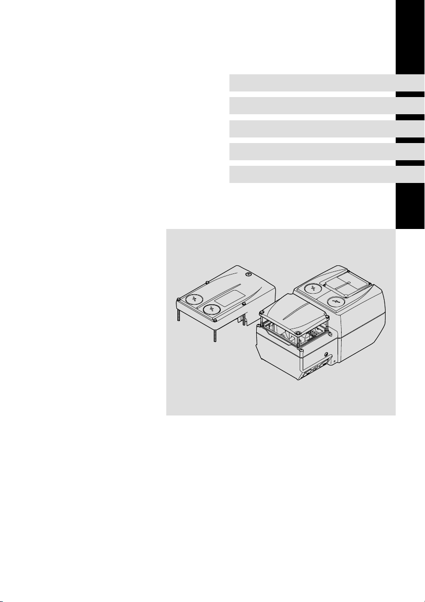
8400 motec 0.37 ... 7.5 kW
E84DGDVBxxx4
Instrucciones para el montaje
Istruzioni per il montaggio
Drive Unit
Page 2

Page 3

Lesen Sie zuerst diese Anleitung, bevor Sie mit den Arbeiten beginnen!
Beachten Sie die enthaltenen Sicherheitshinweise.
Please read these instructions before you start working!
Follow the enclosed safety instructions.
Veuillez lire attentivement cette documentation avant toute action !
Les consignes de sécurité doivent impérativement être respectées.
Lea las instrucciones antes de empezar a trabajar.
Observe las instrucciones de seguridad indicadas.
Prima di usare l’apparecchiatura, leggere le istruzioni contenute in
questo manuale.
Osservare le note di sicurezza.
Page 4
0Abb. 0Tab. 0
0.37 3 kW 4 7.5 kW
E84DG023a E84DG023b
4
EDK84DGDVBxxx4 DE/EN/FR/ES/IT 5.3
Page 5

Inhalt i
1 Über diese Dokumentation 6. . . . . . . . . . . . . . . . . . . . . . . . . . . . . . . . . . . . . . . . .
1.1 Dokumenthistorie 6. . . . . . . . . . . . . . . . . . . . . . . . . . . . . . . . . . . . . . . . . .
1.2 Zielgruppe 6. . . . . . . . . . . . . . . . . . . . . . . . . . . . . . . . . . . . . . . . . . . . . . . .
1.3 Informationen zur Gültigkeit 7. . . . . . . . . . . . . . . . . . . . . . . . . . . . . . . . .
1.4 Verwendete Konventionen 7. . . . . . . . . . . . . . . . . . . . . . . . . . . . . . . . . . .
1.5 Verwendete Hinweise 8. . . . . . . . . . . . . . . . . . . . . . . . . . . . . . . . . . . . . . .
2 Sicherheitshinweise 10. . . . . . . . . . . . . . . . . . . . . . . . . . . . . . . . . . . . . . . . . . . . . . .
3 Technische Daten 12. . . . . . . . . . . . . . . . . . . . . . . . . . . . . . . . . . . . . . . . . . . . . . . . .
3.1 Allgemeine Daten und Einsatzbedingungen 12. . . . . . . . . . . . . . . . . . . .
3.2 Bemessungsdaten 16. . . . . . . . . . . . . . . . . . . . . . . . . . . . . . . . . . . . . . . . . .
4 Mechanische Installation 17. . . . . . . . . . . . . . . . . . . . . . . . . . . . . . . . . . . . . . . . . . .
4.1 Vorbereitung 17. . . . . . . . . . . . . . . . . . . . . . . . . . . . . . . . . . . . . . . . . . . . . .
4.2 Montage 18. . . . . . . . . . . . . . . . . . . . . . . . . . . . . . . . . . . . . . . . . . . . . . . . . .
5 Parametrierung 21. . . . . . . . . . . . . . . . . . . . . . . . . . . . . . . . . . . . . . . . . . . . . . . . . . .
6 Einstellungen 22. . . . . . . . . . . . . . . . . . . . . . . . . . . . . . . . . . . . . . . . . . . . . . . . . . . .
6.1 Grundeinstellungen 25. . . . . . . . . . . . . . . . . . . . . . . . . . . . . . . . . . . . . . . . .
6.2 Einstellen mit dem Handterminal (Keypad) 27. . . . . . . . . . . . . . . . . . . . .
6.3 Maßnahme bei Einsatz in IT−Netzen 29. . . . . . . . . . . . . . . . . . . . . . . . . . .
7 Inbetriebnahme 31. . . . . . . . . . . . . . . . . . . . . . . . . . . . . . . . . . . . . . . . . . . . . . . . . .
EDK84DGDVBxxx4 DE/EN/FR/ES/IT 5.3
5
Page 6
1
Über diese Dokumentation
Dokumenthistorie
1 Über diese Dokumentation
1.1 Dokumenthistorie
Materialnummer Version Beschreibung
13410321 5.3 07/2014 TD15 DE/EN/FR/ES/IT (nur PDF)
13410320 5.2 07/2014 TD15 UL−Hinweise in französischer Sprache für Ca-
13410321 5.1 06/2012 TD15 allgeme Korrekturen, DE/EN/FR/ES/IT (nur
13410320 5.0 06/2012 TD15 allgeme Korrekturen
13392616 4.1 12/2011 TD15 Erweiterung 4 ... 7.5 kW, DE/EN/FR/ES/IT (nur
13392614 4.0 11/2011 TD15 Erweiterung 4 ... 7.5 kW
13373549 3.0 04/2011 TD15 Erweiterung 2.2 ... 3 kW, PROFINET, EtherCAT
13371646 2.0 02/2011 TD15 allgemeine Korrekturen
13336813 1.5 09/2010 TD15 Erstausgabe DE/EN/FR/ES/IT (nur PDF)
13336813 1.0 08/2010 TD15 Erstausgabe DE/EN
Tipp!
Informationen und Hilfsmittel rund um die Lenze−Produkte finden
Sie im Download−Bereich unter
http://www.Lenze.com
nada
EAC−Konformität
PDF)
PDF)
1.2 Zielgruppe
Diese Dokumentation richtet sich an qualifiziertes Fachpersonal nach
IEC 60364.
Qualifiziertes Fachpersonal sind Personen, die für die auszuführenden Tätigkeiten bei der Aufstellung, Montage, Inbetriebsetzung und dem Betrieb des Produkts über entsprechende Qualifikationen verfügen.
6
EDK84DGDVBxxx4 DE/EN/FR/ES/IT 5.3
Page 7

Über diese Dokumentation
Informationen zur Gültigkeit
1
1.3 Informationen zur Gültigkeit
Diese Anleitung ist gültig für Antriebsregler 8400 motec mit der Typenbezeichnung:
Typenbezeichnung ab HW ab SW
E84DGDVBxxx4 VA 01.00
Weitere Informationen zum Typenschlüssel enthält das Kapitel Produktbeschreibung.
1.4 Verwendete Konventionen
Diese Dokumentation verwendet folgende Konventionen zur Unterscheidung
verschiedener Arten von Information:
Informationsart Auszeichnung Beispiele/Hinweise
Zahlenschreibweise
Dezimaltrennzeichen
Warnhinweise
UL−Warnhinweise
UR−Warnhinweise
Textauszeichnung
Programmname » « PC−Software
Symbole
Seitenverweis Verweis auf eine andere Seite mit
Dokumentationsverweis Verweis auf eine andere Dokumen-
Punkt Es wird generell der Dezimalpunkt
verwendet.
Zum Beispiel: 1234.56
Werden in englischer und französischer Sprache verwendet.
Zum Beispiel: »Engineer«, »Global
Drive Control« (GDC)
zusätzlichen Informationen
Zum Beispiel: 16 = siehe Seite 16
tation mit zusätzlichen Informationen
Zum Beispiel: EDKxxx = siehe
Dokumentation EDKxxx
EDK84DGDVBxxx4 DE/EN/FR/ES/IT 5.3
7
Page 8

1
Über diese Dokumentation
Verwendete Hinweise
1.5 Verwendete Hinweise
Um auf Gefahren und wichtige Informationen hinzuweisen, werden in dieser
Dokumentation folgende Piktogramme und Signalwörter verwendet:
Sicherheitshinweise
Aufbau der Sicherheitshinweise:
Gefahr!
(kennzeichnet die Art und die Schwere der Gefahr)
Hinweistext
(beschreibt die Gefahr und gibt Hinweise, wie sie vermieden werden
kann)
Piktogramm und Signalwort Bedeutung
Gefahr!
Gefahr!
Stop!
Anwendungshinweise
Gefahr von Personenschäden durch gefährliche elektrische Spannung
Hinweis auf eine unmittelbar drohende Gefahr, die den
Tod oder schwere Verletzungen zur Folge haben kann,
wenn nicht die entsprechenden Maßnahmen getroffen
werden.
Gefahr von Personenschäden durch eine allgemeine
Gefahrenquelle
Hinweis auf eine unmittelbar drohende Gefahr, die den
Tod oder schwere Verletzungen zur Folge haben kann,
wenn nicht die entsprechenden Maßnahmen getroffen
werden.
Gefahr von Sachschäden
Hinweis auf eine mögliche Gefahr, die Sachschäden zur
Folge haben kann, wenn nicht die entsprechenden Maßnahmen getroffen werden.
Piktogramm und Signalwort Bedeutung
Hinweis!
Tipp!
8
Wichtiger Hinweis für die störungsfreie Funktion
Nützlicher Tipp für die einfache Handhabung
Verweis auf andere Dokumentation
EDK84DGDVBxxx4 DE/EN/FR/ES/IT 5.3
Page 9

Über diese Dokumentation
Verwendete Hinweise
Spezielle Sicherheitshinweise und Anwendungshinweise
Piktogramm und Signalwort Bedeutung
1
Warnings!
Warnings!
Sicherheitshinweis oder Anwendungshinweis für den
Betrieb nach UL− oder CSA−Anforderungen.
Die Maßnahmen sind erforderlich, um die Anforderungen nach UL oder CSA zu erfüllen.
EDK84DGDVBxxx4 DE/EN/FR/ES/IT 5.3
9
Page 10

Sicherheitshinweise2
2 Sicherheitshinweise
Gefahr!
Gefährliche elektrische Spannung
ƒ Die Leistungsanschlüsse führen bis zu 3 Minuten nach
Netz−Ausschalten gefährliche elektrische Spannung.
Mögliche Folgen:
ƒ Tod oder schwere Verletzungen beim Berühren der
Leistungsanschlüsse.
Schutzmaßnahmen:
ƒ Vor Arbeiten am Gerät Netzspannung ausschalten und
mindestens 3 Minuten warten.
ƒ Prüfen, ob alle Leistungsanschlüsse spannungsfrei sind.
Warnung durch Symbole
Symbol Beschreibung
Lange Entladezeit:
Alle Leistungsklemmen führen bis zu 3 Minuten nach Netz−Ausschalten gefährliche
Spannung!
Hoher Ableitstrom:
Festinstallation und PE−Anschluss nach EN 61800−5−1 ausführen!
Elektrostatisch gefährdete Bauelemente:
Vor Arbeiten am Gerät muss sich das Personal von elektrostatischen Aufladungen befreien!
Heiße Oberfläche:
Persönliche Schutzausrüstung verwenden oder Abkühlung abwarten!
10
Beachten Sie auch weitere wichtige Informationen zur Geräte− und
Sicherheitstechnik auf der beiliegenden CD−ROM!
Original − Englisch
Warnings!
Operation of this equipment requires detailed installation and
operation instructions provided in the Hardware manual intended
for use with this product. This information is provided on the
CD−ROM included in the container this device was packaged in. It
should be retained with this device at all times. A hard copy of this
information may be ordered by phone or e−mail, printed on the back
of this document.
EDK84DGDVBxxx4 DE/EN/FR/ES/IT 5.3
Page 11

Original − Französisch
Avertissements !
Pour assurer le bon fonctionnement de cet équipement, se
conformer aux instructions d’installation et de mise en service
contenues dans le manuel correspondant et régissant l’utilisation
de ce produit. Ces informations sont contenues sur le CD−ROM
compris dans l’emballage livré, qui doit être consultable à tout
moment. Une version papier de ces informations peut être
commandée par téléphone ou par mail (coordonnées figurant au
dos du présent document).
Sicherheitshinweise 2
EDK84DGDVBxxx4 DE/EN/FR/ES/IT 5.3
11
Page 12
3
Technische Daten
Allgemeine Daten und Einsatzbedingungen
3 Technische Daten
3.1 Allgemeine Daten und Einsatzbedingungen
Konformität und Approbation
Konformität
CE
EAC TP TC 004/2011
EAC TP TC 020/2011
Approbation
UR UL 508C
UR C22.2 No 14
C
2006/95/EG Niederspannungsrichlinie
Über die Sicherheit
(TR ZU 004/2011)
(TR ZU 020/2011)
von Niederspannungsausrüstung
Elektromagnetische
Verträglichkeit von
technischen Erzeugnissen
Power Conversion
Equipment, File No.
E170350
Eurasische Konformität
TR ZU: Technische Regulierung der Zollunion
Eurasische Konformität
TR ZU: Technische Regulierung der Zollunion
12
EDK84DGDVBxxx4 DE/EN/FR/ES/IT 5.3
Page 13

Technische Daten
Allgemeine Daten und Einsatzbedingungen
Personenschutz und Geräteschutz
Schutzart
(Erd−) Ableitstrom EN 61800−5−1 > 3.5 mA AC,
Summen−Fehlerstrom In TN−Netzen dürfen folgende Fehlerstrom−Schutz-
Motormontage
Wandmontage E84DGDVB3714
zusätzlicher Potenzialausgleich
Isolierung von Steuerschaltkreisen
Isolationsfestigkeit EN 61800−5−1
Kurzschlussfestigkeit EN 61800−5−1
Erdschlussfestigkeit EN 61800−5−1
Einschaltstrom £ 2 x I
EN 60529 IP65
NEMA 250 Schutz nach
EN 61800−5−1 Sichere Trennung vom Netz durch doppelte (ver-
optional: IP66
l Typ 4
> 10 mA DC
schalter eingesetzt werden:
E84DGDVB3714
...
E84DGDVB1524
E84DGDVB2224
...
E84DGDVB7524
...
E84DGDVB7524
M5−Gewinde mit Klemme in der WU für den Anschluss einer 16mm@ PE−Leitung
stärkte) Isolierung
Aufstellhöhe
0 ... 2000 m Überspannungskategorie III
2000 ... 4000 m Überspannungskategorie II
Anschluss:
Motor
Motorhaltebremse,
Bremswiderstand
PTC, Steueranschlüsse voll
Anschluss:
Motor (bei Regler-
freigabe)
Motor (im Betrieb)
Bremswiderstand, PTC
N
im betriebsfertigen
Zustand:
l Nicht benutzte
Bohrungen für Kabelverschraubungen mit Blindstopfen verschließen!
l Nicht benutzte Steck-
verbinder mit Schutzkappen oder Blindsteckern
verschließen!
Bestimmungen und Sicherheitshinweise beachten!
30 mA, Typ B
300 mA, Typ B
300 mA, Typ B
bedingt, der Regler wird gesperrt, Fehlerquittierung
erforderlich
nein
bedingt, der Regler wird gesperrt, Fehlerquittierung
erforderlich
nein
nein
3
EDK84DGDVBxxx4 DE/EN/FR/ES/IT 5.3
13
Page 14

3
Technische Daten
Allgemeine Daten und Einsatzbedingungen
Anschlussbedingungen
Netzanschluss
Netzsystem
TT, TN
(mit geerdetem
Sternpunkt)
IT Die für IT−Netze beschriebene Maßnahme anwenden
Motoranschluss
Motoren EN 60034 Nur für den Umrichterbetrieb geeignete Motoren
Länge der Motorleitung
Umgebungsbedingungen
Klimatisch
Lagerung
Transport IEC/EN 60721−3−2 2K3 (−30 ... +75 °C)
Betrieb IEC/EN 60721−3−3 3K3 (−30 ... +55 °C)
Aufstellhöhe < 4000 m üNN
Verschmutzung IEC/EN 61800−5−1 Verschmutzungsgrad 2
Mechanisch
Rüttelfestigkeit (9.81 m/s
Motormontage
Wandmontage
mit
E84DZMAWE1
IEC/EN 60721−3−1 1K3 (−30 ... +60 °C)
2
= 1 g)
Germanischer
Lloyd
IEC/EN 60721−3−3 3M6
Germanischer
Lloyd
IEC/EN 60721−3−3 3M6
Betrieb uneingeschränkt erlaubt.
(IT−Schraube entfernen).
Die Einhaltung der EMV−Anforderungen für die
Störaussendung (EN 61800−3) für die Maschine/
Anlage liegt in der Verantwortung des Maschinen−/
Anlagenherstellers!
Der Betrieb mit integrierter Sicherheitstechnik ist
nicht zulässig.
einsetzen. Isolationsfestigkeit:
min. û ³ 1.5 kV, min. du/dt ³ 5 kV/ms
< 20 m (Lenze−Systemleitung, geschirmt)
Betrieb bei 4 kHz: > +45 °C den Ausgangs−Bemessungsstrom um 2,5 %/°C reduzieren.
Betrieb bei 8/16 kHz: > +40 °C den Ausgangs−Bemessungsstrom um 2,5 %/°C reduzieren.
> 1000 m üNN den Ausgangs−Bemessungsstrom um
5 %/ 1000 m reduzieren.
Allgemeine Bedingungen: beschleunigungsfest bis
2 g
Allgemeine Bedingungen: beschleunigungsfest bis
2 g
14
EDK84DGDVBxxx4 DE/EN/FR/ES/IT 5.3
Page 15

Allgemeine Daten und Einsatzbedingungen
Montagebedingungen
Einbauort
Motormontage
Wandmontage mit optionalem
Einbaulage
Wandmontage
E84DGDVB3714
...
E84DGDVB3024
E84DGDVB4024
...
E84DGDVB7524
Steuerung
Steuerungsverfahren
VFCplus:
l U/f−Steuerung (linear oder quadratisch)
SLVC:
l Sensorlose Vectorregelung (Drehzahl)
VFCplus eco:
l energieeffiziente U/f−Steuerung
Schaltfrequenz
4 kHz, 8 kHz, 16 kHz,
Standard
Wandadapter
vertikal, Kühlrippen
oben
bliebig
Technische Daten
In Nischen die Konvektionskühlung gewährleisten!
Anreihen mehrer Geräte nur
seitlich, damit die Konvektionskühlung gewährleistet
bleibt!
3
EDK84DGDVBxxx4 DE/EN/FR/ES/IT 5.3
15
Page 16
3
Technische Daten
Bemessungsdaten
3.2 Bemessungsdaten
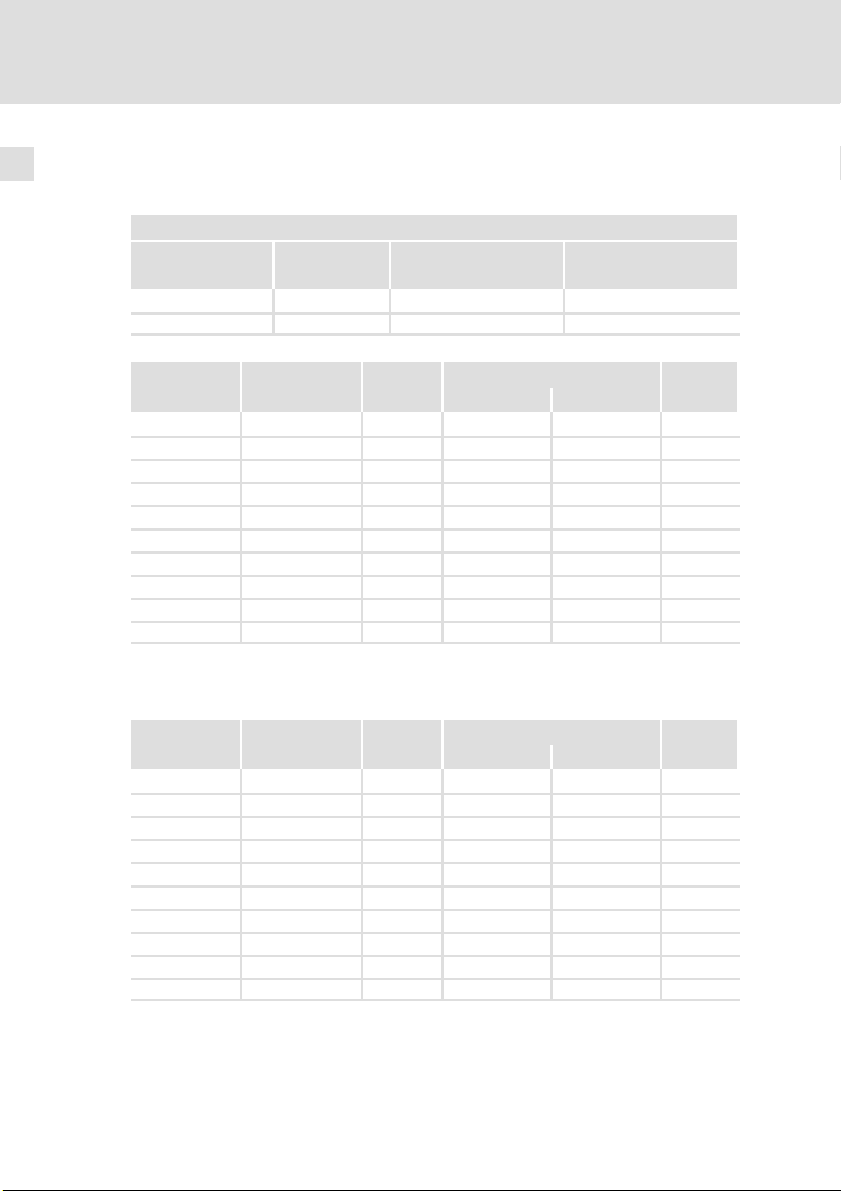
Eingangsdaten
Grundlage der Daten
Netz Spannung Spannungsbereich Frequenzbereich
3/PE AC 400 320 − 0 % ... 440 + 0 % 45 − 0 % ... 65 + 0 %
3/PE AC 480 432 − 0 % ... 528 + 0 % 45 − 0 % ... 65 + 0 %
E84DGDVB3714 400/480 50/60 1.3/1.1 1.0/0.8 3
E84DGDVB5514 400/480 50/60 1.8/1.5 1.4/1.1 3
E84DGDVB7514 400/480 50/60 2.4/2.0 1.8/1.5 3
E84DGDVB1124 400/480 50/60 3.2/2.7 2.4/2.0 3
E84DGDVB1524 400/480 50/60 3.8/3.1 2.9/2.3 3
E84DGDVB2224 400/480 50/60 5.6/4.6 4.2/3.5 3
E84DGDVB3024 400/480 50/60 7.2/5.9 5.4/4.4 3
E84DGDVB4024 400/480 50/60 9.3/7.7 7.0/5.8 3
E84DGDVB5524 400/480 50/60 12.8/10.6 9.6/8.0 3
E84DGDVB7524 400/480 50/60 16.3/13.5 12.3/10.1 3
Umgebungstemperatur, Schaltfrequenz 4 kHz
Ausgangsdaten
U
[V] U
LN
Spannung Frequenz Bemessungsstrom [A]
[V] [Hz] bis +45 °C bis +55 °C
[V] f [Hz]
LN
Phasen-
zahl
16
Spannung Frequenz Bemessungsstrom [A]
[V] [Hz] bis +45 °C bis +55 °C
E84DGDVB3714 0 ... 400/480 0 ... 300 1.3/1.1 1.0/0.8 3
E84DGDVB5514 0 ... 400/480 0 ... 300 1.8/1.5 1.4/1.1 3
E84DGDVB7514 0 ... 400/480 0 ... 300 2.4/2.0 1.8/1.5 3
E84DGDVB1124 0 ... 400/480 0 ... 300 3.2/2.7 2.4/2.0 3
E84DGDVB1524 0 ... 400/480 0 ... 300 3.9/3.2 2.9/2.4 3
E84DGDVB2224 0 ... 400/480 0 ... 300 5.6/4.7 4.2/3.5 3
E84DGDVB3024 0 ... 400/480 0 ... 300 7.3/6.0 5.4/4.5 3
E84DGDVB4024 0 ... 400/480 0 ... 300 9.5/7.9 7.1/5.9 3
E84DGDVB5524 0 ... 400/480 0 ... 300 13.0/10.8 9.8/8.1 3
E84DGDVB7524 0 ... 400/480 0 ... 300 16.5/13.7 12.4/10.3 3
Umgebungstemperatur, Schaltfrequenz 4 kHz
EDK84DGDVBxxx4 DE/EN/FR/ES/IT 5.3
Phasen-
zahl
Page 17

4 Mechanische Installation
4.1 Vorbereitung
Die Montage und Verdrahtung der Wiring Unit und Communication Unit
entsprechend der Montageanleitungen muss abgeschlossen sein.
Bevor Sie die Montage des 8400 motec fortführen und abschließen können,
müssen Entscheidungen zur Parametrierung und Inbetriebnahme getroffen
sein. Davon abhängig ist das weitere Vorgehen.
Soll der Antriebsregler mit L−Force »Engineer« oder mit einem Handterminal
parametriert werden?
ƒ Drive Unit montieren
Soll der Antriebsregler mit DIP1, DIP2, P2 oder P3 voreingestellt werden?
ƒ Einstellungen nach Anforderungen vornehmen
– Das Kapitel Einstellungen enthält die notwendigen Information.
ƒ Drive Unit montieren
Ist der Antriebsregler Bestandteil eines Drive Package?
ƒ Der Antriebsregler ist in Abstimmung mit Motor und Getriebe werkseitig
eingestellt.
ƒ Werkseitige Einstellungen nicht verändern!
ƒ Drive Unit montieren
Mechanische Installation
Vorbereitung
4
EDK84DGDVBxxx4 DE/EN/FR/ES/IT 5.3
17
Page 18
4
Mechanische Installation
Montage
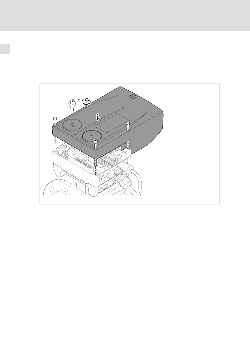
4.2 Montage
0.37 ... 3 kW
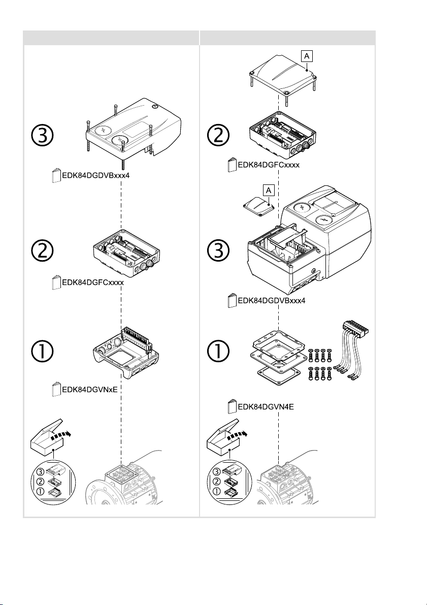
Setzen Sie die Drive Unit −ohne zu verkanten− auf die vorher montierte Communication Unit auf. Befestigen Sie die Drive Unit mit den gelieferten vier
Schrauben (Drehmoment: 5.0 Nm/44 lb−in).
E84DG043
18
EDK84DGDVBxxx4 DE/EN/FR/ES/IT 5.3
Page 19
Mechanische Installation
Montage
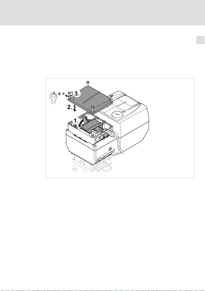
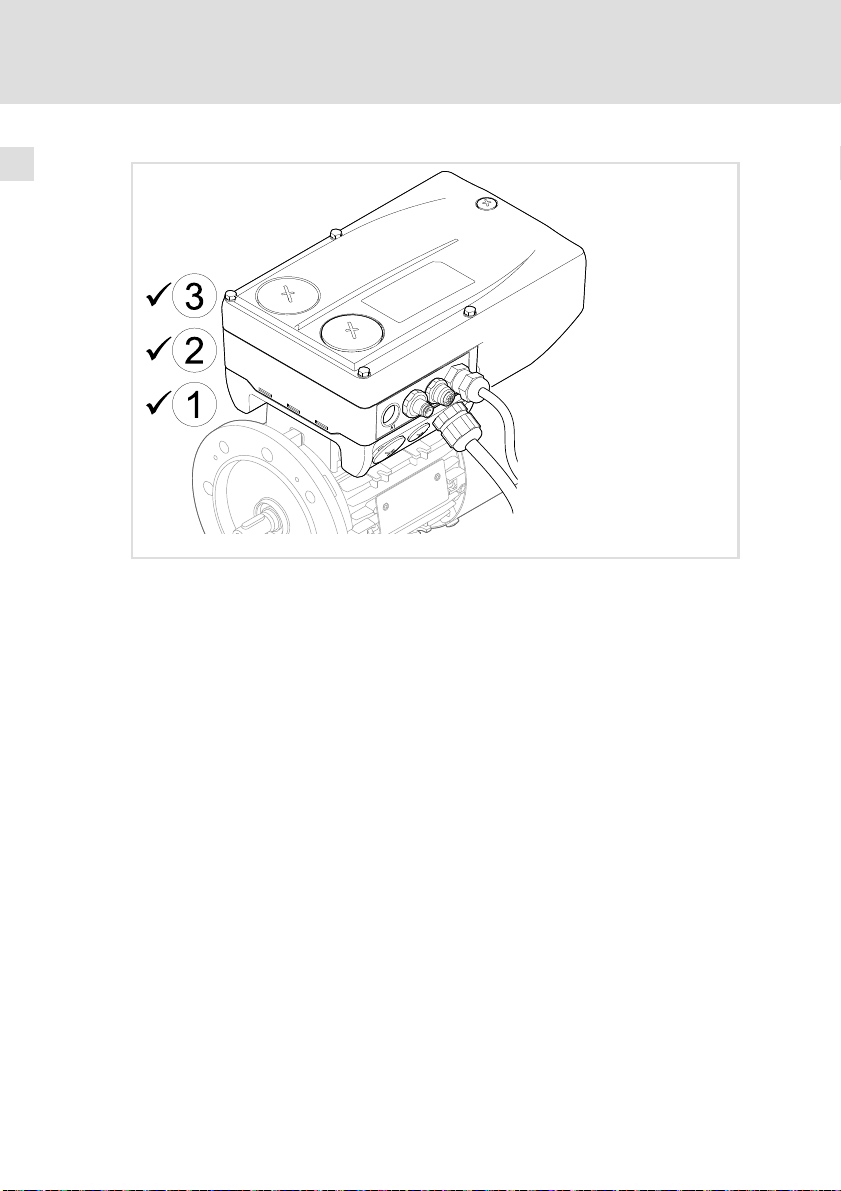
4 ... 7.5 kW
Die Drive Unit wurde bereits mit der Wiring Unit montiert.
So schließen Sie die Montage ab:
1. Die klappbare Buchsenleiste zur CU drehen und vorsichtig in den
Gegenstecker drücken.
2. Deckel der DU auf die Communication Unit setzen und
3. mit den vier Schrauben befestigen (Drehmoment: 1.5 Nm/14 lb−in).
4
EDK84DGDVBxxx4 DE/EN/FR/ES/IT 5.3
E84DG081
19
Page 20
4
Mechanische Installation
Montage
E84DG042
20
EDK84DGDVBxxx4 DE/EN/FR/ES/IT 5.3
Page 21

5 Parametrierung
Durch Parametrierung können Sie den Antriebsregler auf verschiedene Anforderungen von Anwendungen optimal einstellen.
Die Parametrierung kann auf folgende Arten erfolgen:
Parametrierung mit L−force »Engineer«
ƒ Umfangreiche Einstellungen Online per Software
– Erfordert Software und USB−Diagnoseadapter
Parametrierung mit Handterminal/Keypad
ƒ Einstellung bestimmter Parameter durch erfahrene Anwender
– Erfordert ein für 8400 motec geeignetes Handterminal
Hinweis!
Parametereinstellungen netzausfallsicher speichern
Damit im Gerät vorgenommene Parametereinstellungen nicht durch
ein Netzschalten verloren gehen, müssen Sie den Parametersatz
explizit im Gerät netzausfallsicher speichern.
Parametrierung 5
EDK84DGDVBxxx4 DE/EN/FR/ES/IT 5.3
21
Page 22

Einstellungen6
6 Einstellungen
Für die erste Inbetriebnahme können Sie Einstellungen per DIP−Schalter und
Potentiometer vornehmen. Die Einstellungen müssen vor Montage der
Drive Unit vorgenommen werden, da die Einstellelemente von außen nicht
zugänglich sind.
Stop!
Automatischer Motoranlauf
Im "Local mode" ist die Autostart−Option "Sperre bei Netzein" nicht
gesetzt. Der Motor läuft mit dem Netzeinschalten an, wenn die
Reglerfreigabe RFR gebrückt oder gesetzt ist.
("Local mode" => DIP1/1 = ON und DIP2/5−7 = OFF)
Mögliche Folgen:
ƒ Gefahren oder Schäden durch den unerwarteten Motoranlauf.
Schutzmaßnahmen:
ƒ Bei der Inbetriebnahme den Motor vom Antriebsstrang
entkoppeln.
ƒ Ersetzen der werkseitigen Brücke an RFR durch einen Schließer.
ƒ Reglerfreigabe nicht setzen.
22
EDK84DGDVBxxx4 DE/EN/FR/ES/IT 5.3
Page 23
Einstellungen 6
Einstellelemente 0.37 ... 3 kW
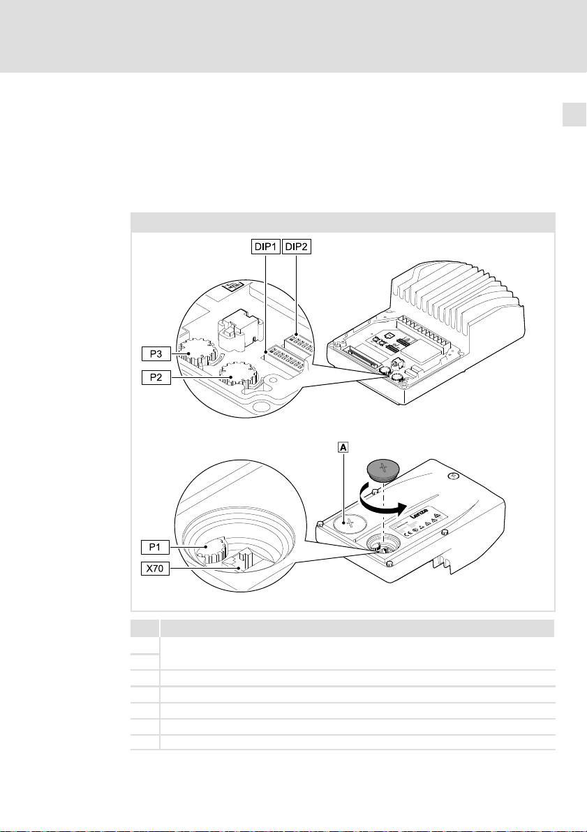
Auf der Innenseite der Drive Unit finden Sie die Einstellelemente.
Vorgenommene Einstellungen durch DIP1, DIP2, P2, P3 und P1 müssen mit
DIP1/1 aktiviert werden. Die Einstellungen werden bei jedem Netzeinschalten
erneut übernommen. Zwischenzeitliche Änderungen an Parametern können
dadurch überschrieben werden.
0.37 ... 3 kW
E84DG041
Bezeichnung
DIP1
Schalter zur Schnellinbetriebnahme−Grundeinstellungen
DIP2
P1 Einstellung "Top Cover: Speed ... %"
P2 Einstellung "Speed ... %", (Drehzahl)
P3 Einstellung "Ramp ... s", (Auf− / Ablaufzeit)
X70 Anschluss für USB−Diagnoseadapter E94AZCUS oder Handterminal
LED−Statusanzeige
EDK84DGDVBxxx4 DE/EN/FR/ES/IT 5.3
E84DG044
23
Page 24
Einstellungen6
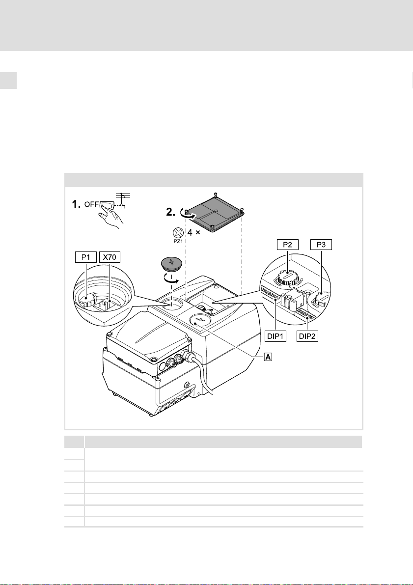
Einstellelemente 4 ... 7.5 kW
Auf der Oberseite der Drive Unit finden Sie die Einstellelemente.
ƒ Spannungsfreiheit sicherstellen und gegen Wiedereinschalten sichern.
ƒ Kleinen Deckel auf der Oberseite abnehmen.
Vorgenommene Einstellungen durch DIP1, DIP2, P2, P3 und P1 müssen mit
DIP1/1 aktiviert werden. Die Einstellungen werden bei jedem Netzeinschalten
erneut übernommen. Zwischenzeitliche Änderungen an Parametern können
dadurch überschrieben werden.
4 ... 7.5 kW
24
Bezeichnung
DIP1
Schalter zur Schnellinbetriebnahme−Grundeinstellungen
DIP2
P1 Einstellung "Top Cover: Speed ... %"
P2 Einstellung "Speed ... %", (Drehzahl)
P3 Einstellung "Ramp ... s", (Auf− / Ablaufzeit)
X70 Anschluss für USB−Diagnoseadapter E94AZCUS oder Handterminal
LED−Statusanzeige
EDK84DGDVBxxx4 DE/EN/FR/ES/IT 5.3
E84DG083
Page 25
Einstellungen
Grundeinstellungen
6
6.1 Grundeinstellungen
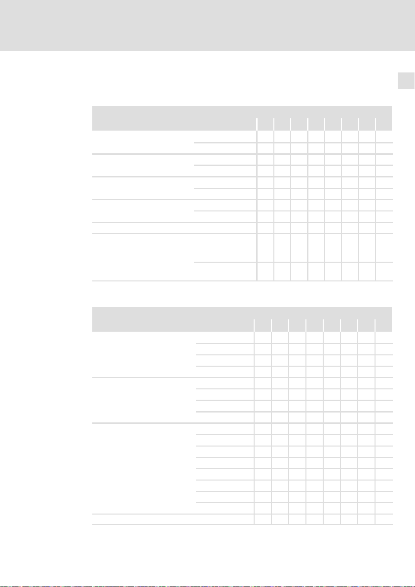
Einstellmöglichkeiten mit DIP1
DIP1 Schalter
Beschreibung 1 2 3 4 5 6 7 8
Einstellungen nach DIP1, DIP2,
P1, P2 und P3 aktiv
Drehrichtung
Regelung
Fangschaltung
reserviert − OFF OFF OFF
Meldungstyp −> an
(nur optional mit Communication Unit "+ Safety")
Einstellmöglichkeiten mit DIP2
DIP2 Schalter
Beschreibung 1 2 3 4 5 6 7 8
Motornennfrequenz
Modus des analogen Eingangs
(nur optional mit Communication Unit "+ Safety")
Steuermodus Technologieapplikation
(vergleiche Auswahl C00007)
reserviert − OFF
(Lenze−Einstellung fett)
ein ( I )
aus ( 0 )
links
rechts
quadratisch
linear
ein ( I )
aus ( 0 )
fail −> DO
ready −> NO
(Relais)
ready −> DO
fail −> NO (Relais)
50 Hz
60 Hz
87 Hz
120 Hz
0 ... 10 V
0 ... 20 mA
4 ... 20 mA
nicht zulässig ON ON
9 (Local mode)
10 (Klemmen 0)
12 (Klemmen 2)
14 (Klemmen 11)
16 (Klemmen 16)
reserviert
reserviert
40 (MCI)
ON
OFF
ON
OFF
ON
OFF
OFF OFF
ON OFF
OFF ON
ON ON
OFF OFF
ON OFF
OFF ON
ON
OFF
ON
OFF
OFF OFF OFF
ON OFF OFF
OFF ON OFF
ON ON OFF
OFF OFF ON
ON OFF ON
OFF ON ON
ON ON ON
EDK84DGDVBxxx4 DE/EN/FR/ES/IT 5.3
25
Page 26
6
Einstellungen
Grundeinstellungen
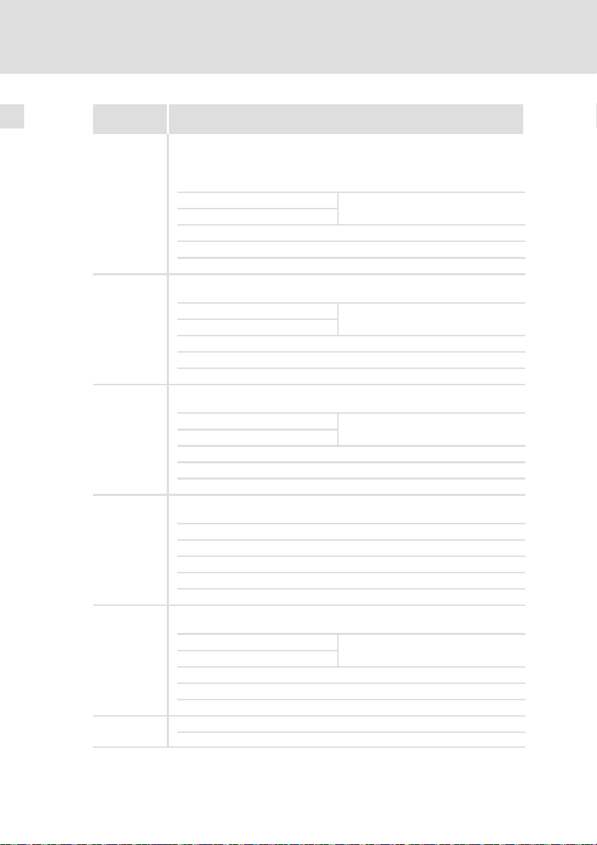
Steuermodi
DIP2/5−7
9
(Local mode)
10
(Klemmen 0)
12
(Klemmen 2)
14
(Klemmen 11)
16
(Klemmen 16)
40
(MCI)
Beschreibung
(DIx High)
Die Steuerung der Technologieapplikation erfolgt lokal über Elemente am
Antriebsregler und die digitalen Eingangsklemmen:
Bei Netzeinschalten läuft der Motor automatisch an, wenn RFR gebrückt
oder gesetzt ist!
DI1 Sollwert von P2 (Speed)
DI2 Festsollwert 2
DI3 Gleichstrombremse aktivieren
DI4 Drehrichtungswechsel (nicht möglich, wenn DIP1/2 = on (links) ist)
DI5 Haltebremse manuell lüften (Betriebsmodus nach Einstellung C02580)
Die Steuerung der Technologieapplikation erfolgt über die digitalen Eingangsklemmen des Antriebsreglers:
DI1 Festsollwert 1
DI2 Festsollwert 2
DI3 Gleichstrombremse aktivieren
DI4 Drehrichtungswechsel
DI5 Haltebremse manuell lüften (Betriebsmodus nach Einstellung C02580)
Die Steuerung der Technologieapplikation erfolgt über die digitalen Eingangsklemmen des Antriebsreglers:
DI1 Festsollwert 1
DI2 Festsollwert 2
DI3 Schnellhalt
DI4 Drehrichtungswechsel
DI5 Haltebremse manuell lüften (Betriebsmodus nach Einstellung C02580)
Die Steuerung der Technologieapplikation erfolgt über die digitalen Eingangsklemmen des Antriebsreglers:
DI1 Drehrichtungswechsel
DI2 Gleichstrombremse aktivieren
DI3 Motorpotentiometer: Drehzahl höher
DI4 Motorpotentiometer: Drehzahl tiefer
DI5 Haltebremse manuell lüften (Betriebsmodus nach Einstellung C02580)
Die Steuerung der Technologieapplikation erfolgt über die digitalen Eingangsklemmen des Antriebsreglers:
DI1 Festsollwert 1
DI2 Festsollwert 2
DI3 Rechtslauf/Schnellhalt
DI4 Linkslauf/Schnellhalt
DI5 Haltebremse manuell lüften (Betriebsmodus nach Einstellung C02580)
Die Steuerung der Technologieapplikation erfolgt per Feldbuskommunikation.
Abhängig von der vorhandenen Communication Unit
Festsollwert 3
Festsollwert 3
Festsollwert 3
Festsollwert 3
26
EDK84DGDVBxxx4 DE/EN/FR/ES/IT 5.3
Page 27
Einstellungen
Einstellen mit dem Handterminal (Keypad)
Einstellmöglichkeiten mit P2 "Speed"
Mit P2 kann in 10 Stufen ein Sollwert Motordrehzahl in Prozent der
Nenndrehzahl in C00011 voreingestellt werden (JOG−Festsollwert). Der
JOG−Sollwert wird nur aktiviert, wenn im "Local mode" der Eingang DI1 gesetzt
wird.
P2 Stellung
Beschreibung 0 1 2 3 4 5 6 7 8 9
Motordrehzahl in Prozent der Einstellung
Nenndrehzahl C00011
Einstellmöglichkeiten mit P3 "Ramp"
P3 Stellung
Beschreibung 0 1 2 3 4 5 6 7 8 9
Auf− oder Ablaufzeit des Motors in
Sekunden
Einstellmöglichkeiten mit P1
Das Potentiometer P1 wird zugänglich nach entfernen des Verschlussdeckels.
Um den Schutzgrad des Antriebsreglers zu gewährleisten, muss der Verschlussdeckel nach den Einstellungen wieder eingeschraubt werden.
Während des Betriebes kann mit P1 stufenlos die Motordrehzahl in Prozent der
Nenndrehzahl in C00011 eingestellt werden, sofern kein JOG−Festsollwert P2
über DI1 aktiv ist.
[%] 0 11 22 33 44 55 66 77 88 100
[s] 0.1 0.5 1 2 5 10 20 30 60 120
6
P1 Stellung
Beschreibung 0 ... 9
Motordrehzahl in Prozent der Nenndrehzahl
C00011
[%] 0 ... 100
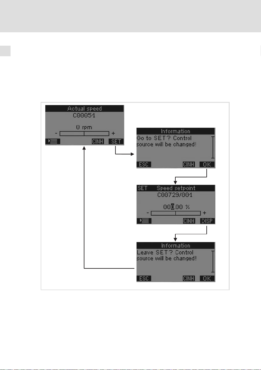
6.2 Einstellen mit dem Handterminal (Keypad)
Der Antriebsregler kann auch mit dem Handterminal eingestellt und gesteuert
werden. Das Handterminal beinhaltet Griffschale, Anschlussleitung und das
Keypad, welches bei diesem Antriebsregler nicht direkt aufgesteckt werden
kann. Beschreibungen zum Keypad sind mit dem Handterminal anwendbar.
Wird das Handterminal angeschlossen, erscheint nach der Initialisierung die
Anzeige eines vorgewählten Parameters. In der Lenze−Einstellung wird der
Drehzahlistwert (C00051) angezeigt. Der vorgewählte Parameter kann
verändert werden (C00466).
EDK84DGDVBxxx4 DE/EN/FR/ES/IT 5.3
27
Page 28
6
Einstellungen
Einstellen mit dem Handterminal (Keypad)
"SET"−Modus
Aus dem Anzeige−Modus kann mit der rechten Softkey−Taste "SET" in den
SET−Modus gewechselt werden. Im SET−Modus kann der Drehzahl−Sollwert
verändert und der Antriebsregler freigegeben oder gesperrt werden (RFR/run).
Verlassen wird der SET−Modus mit der rechten Softkey−Taste "DISP". Der
Wechsel der Modi muss jeweils mit der rechten Softkey−Taste "OK" bestätigt
werden.
28
EDK84DGDVBxxx4 DE/EN/FR/ES/IT 5.3
Page 29
Einstellen mit dem Handterminal (Keypad)
Maßnahme bei Einsatz in IT−Netzen
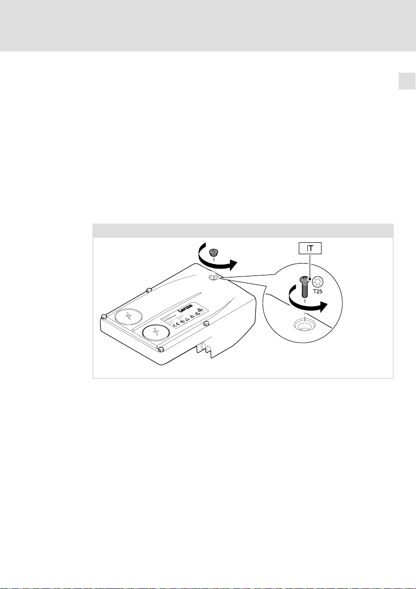
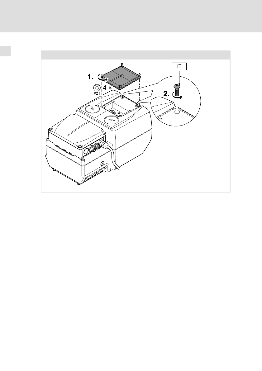
6.3 Maßnahme bei Einsatz in IT−Netzen
Wird der Antrieb in einem IT−Netz installiert, müssen interne Filter vom Schutzleiter getrennt werden.
So gehen Sie vor:
1. Bei bereits montiertem Antriebsregler: Netzspannung abschalten!
2. IT−Schraube zugänglich machen.
– Geräte bis 3 kW: Kleine Verschlusskappe auf der Oberseite heraus
drehen.
– Geräte ab 4 kW: Kleinen Deckel auf der Oberseite abnehmen.
3. Die Schraube(n) heraus drehen und entfernen.
4. Verschlusskappe hinein drehen oder Deckel anbringen.
IT−Netz
0.37 ... 3 kW
Einstellungen
6
EDK84DGDVBxxx4 DE/EN/FR/ES/IT 5.3
E84DG046
29
Page 30
6
Einstellungen
Einstellen mit dem Handterminal (Keypad)
Maßnahme bei Einsatz in IT−Netzen
4 ... 7.5 kW
E84DG084
30
EDK84DGDVBxxx4 DE/EN/FR/ES/IT 5.3
Page 31

7 Inbetriebnahme
Voraussetzungen für das erste Einschalten
ƒ Die Wiring Unit ist gemäß Anleitung montiert und verdrahtet,
– direkt auf einem Motorklemmflansch oder
– mit dem Wandadapter auf einer geeigneten Fläche nahe des Motors.
ƒ Anschlüsse mit Netz, Motor, Haltebremsen usw. sind hergestellt.
ƒ Die Communication Unit wurde montiert und entsprechend der geplanten
Anwendung verdrahtet.
– Eingangs− und Ausgangssignale
– Sicherer Eingang
– Feldbus
(je nach Ausführung nur optional vorhanden)
ƒ Bei Bedarf wurden die Grundeinstellungen für "Local mode"
vorgenommen.
– DIP−Schalter
– Potentiometer
ƒ Die Drive Unit wurde montiert und verschraubt.
ƒ Vorhandene Steuerfunktionen sinnvoll einsetzen, z. B.
– Reglerfreigabe sperren
– Geschwindigkeitseinstellung auf minimal einstellen
– Sicherheitseinrichtung aktivieren
ƒ Der Einsatz eines Bremswiderstandes wurde geprüft.
– Bei dynamischen Belastungen oder schwierigen Regelverhältnissen wird
für die Geräte E84DGDVB4024 ... 7524 (4 ... 7.5 kW) immer der Einsatz
des internen Bremswiderstandes E84DZEW47R0 empfohlen.
Inbetriebnahme 7
Gefahr!
Hohes Gefahrenpotential während der Inbetriebnahme
Durch fehlerhafte Einstellungen kann es zu unerwarteten und
gefährlichen Motor− und Anlagenbewegungen kommen.
Mögliche Folgen:
ƒ Sachschäden
ƒ Personenschäden
Schutzmaßnahmen:
ƒ Gefahrenbereich räumen
ƒ Sicherheitsvorschriften und Sicherheitsabstände einhalten
EDK84DGDVBxxx4 DE/EN/FR/ES/IT 5.3
31
Page 32

Inbetriebnahme7
Inbetriebnahme
Gehen Sie Schrittweise vor:
ƒ Netz einschalten
ƒ Statusanzeige beobachten
– Nach kurzer Initialisierungszeit muss die Anzeige grün blinken.
ƒ Anforderungen der Sicherheitsfunktion deaktivieren
ƒ Reglerfreigabe setzen
– Der Motor muss nach der eingestellten Anlaufzeit mit der eingestellten
Geschwindigkeit drehen.
ƒ Erste Prüfung des erwartungsgemäßen Verhaltens:
– Drehrichtung?
– Anlaufzeit?
– Geschwindigkeit?
– Geschwindigkeitsregelung?
ƒ Prüfung optionaler Steuerungsfunktionen:
– Funktioniert die analoge Sollwertvorgabe?
– Funktionieren digitale Steuersignale, z. B. Endschalter?
– Funktioniert die angeschlossene Motorhaltebremse?
– Funktioniert die Drehrichtungsumschaltung
– Funktioniert die Anforderung der Sicherheitsfunktion?
– Funktionieren Steuersignale über Feldbus?
ƒ Antrieb abschalten
– Geschwindigkeit reduzieren
– Reglerfreigabe sperren
– Netz ausschalten
32
Abhängig vom Bussystem der Communication Unit werden Zustände mit einer
LED−Anzeige signalisiert. Ausführliche Informationen enthält das Kommunikationshandbuch zum verwendeten Bussystem.
LED 1 (green) 2 (green) 3 (red) 4 (red)
PROFIBUS BUS STATE MODULE STATE BUS ERROR MODULE ERROR
AS−i SLAVE 1 READY SLAVE 2 READY SLAVE 1 ERROR SLAVE 2 ERROR
E84DG056_b
EtherCAT RUN LINK/ACTIVITY ERROR LINK/ACTIVITY
PROFINET BUS READY LINK/
EtherNet/
IP
MODULE STATE NETWORK STATE
ACTIVITY 1
(yellow)
(red) (green)
BUS ERROR LINK/ACTIVITY 2
EDK84DGDVBxxx4 DE/EN/FR/ES/IT 5.3
(green)
(yellow)
Page 33

EDK84DGDVBxxx4 DE/EN/FR/ES/IT 5.3
33
Page 34

0Fig. 0Tab. 0
0.37 3 kW 4 7.5 kW
34
E84DG023a E84DG023b
EDK84DGDVBxxx4 DE/EN/FR/ES/IT 5.3
Page 35

Contents i
1 About this documentation 36. . . . . . . . . . . . . . . . . . . . . . . . . . . . . . . . . . . . . . . . . .
1.1 Document history 36. . . . . . . . . . . . . . . . . . . . . . . . . . . . . . . . . . . . . . . . . .
1.2 Target group 36. . . . . . . . . . . . . . . . . . . . . . . . . . . . . . . . . . . . . . . . . . . . . .
1.3 Validity information 37. . . . . . . . . . . . . . . . . . . . . . . . . . . . . . . . . . . . . . . .
1.4 Conventions used 37. . . . . . . . . . . . . . . . . . . . . . . . . . . . . . . . . . . . . . . . . . .
1.5 Notes used 38. . . . . . . . . . . . . . . . . . . . . . . . . . . . . . . . . . . . . . . . . . . . . . . .
2 Safety instructions 40. . . . . . . . . . . . . . . . . . . . . . . . . . . . . . . . . . . . . . . . . . . . . . . .
3 Technical data 42. . . . . . . . . . . . . . . . . . . . . . . . . . . . . . . . . . . . . . . . . . . . . . . . . . . .
3.1 General data and operating conditions 42. . . . . . . . . . . . . . . . . . . . . . . .
3.2 Rated data 46. . . . . . . . . . . . . . . . . . . . . . . . . . . . . . . . . . . . . . . . . . . . . . . .
4 Mechanical installation 47. . . . . . . . . . . . . . . . . . . . . . . . . . . . . . . . . . . . . . . . . . . .
4.1 Preparation 47. . . . . . . . . . . . . . . . . . . . . . . . . . . . . . . . . . . . . . . . . . . . . . . .
4.2 Mounting 48. . . . . . . . . . . . . . . . . . . . . . . . . . . . . . . . . . . . . . . . . . . . . . . . .
5 Parameter setting 51. . . . . . . . . . . . . . . . . . . . . . . . . . . . . . . . . . . . . . . . . . . . . . . . .
6 Settings 52. . . . . . . . . . . . . . . . . . . . . . . . . . . . . . . . . . . . . . . . . . . . . . . . . . . . . . . . .
6.1 Basic settings 55. . . . . . . . . . . . . . . . . . . . . . . . . . . . . . . . . . . . . . . . . . . . . .
6.2 Setting with the diagnosis terminal (keypad) 57. . . . . . . . . . . . . . . . . . . .
6.3 Measures when drive is used in IT systems 59. . . . . . . . . . . . . . . . . . . . . .
7 Commissioning 61. . . . . . . . . . . . . . . . . . . . . . . . . . . . . . . . . . . . . . . . . . . . . . . . . .
EDK84DGDVBxxx4 DE/EN/FR/ES/IT 5.3
35
Page 36

1
About this documentation
Document history
1 About this documentation
1.1 Document history
Material number Version Description
13410321 5.3 07/2014 TD15 DE/EN/FR/ES/IT (only PDF)
13410320 5.2 07/2014 TD15 UL notes in French for Canada
13410321 5.1 06/2012 TD15 General corrections, DE/EN/FR/ES/IT (only
13410320 5.0 06/2012 TD15 General corrections
13392616 4.1 12/2011 TD15 Extension 4 ... 7.5 kW, DE/EN/FR/ES/IT (only
13392614 4.0 11/2011 TD15 Extension 4 ... 7.5 kW
13373549 3.0 04/2011 TD15 Extension 2.2 ... 3 kW, PROFINET, EtherCAT
13371646 2.0 02/2011 TD15 General corrections
13336813 1.5 09/2010 TD15 First edition DE/EN/FR/ES/IT (only PDF)
13336813 1.0 08/2010 TD15 First edition DE/EN
Tip!
Information and auxiliary devices related to the Lenze products can
be found in the download area at
http://www.Lenze.com
EAC Conformity
PDF)
PDF)
1.2 Target group
This documentation is directed at qualified skilled personnel according to
IEC 60364.
Qualified skilled personnel are persons who have the required qualifications to
carry out all activities involved in installing, mounting, commissioning, and
operating the product.
36
EDK84DGDVBxxx4 DE/EN/FR/ES/IT 5.3
Page 37

About this documentation
Validity information
1
1.3 Validity information
These instructions are valid for 8400 motec controllers with the following type
designation:
Type designation From HW From SW
E84DGDVBxxx4 VA 01.00
Further information on the type code can be obtained from the "Product
description" chapter.
1.4 Conventions used
This documentation uses the following conventions to distinguish between
different types of information:
Type of information Identification Examples/notes
Spelling of numbers
Decimal separator
Warnings
UL warnings
UR warnings
Text
Program name » « PC software
Icons
Page reference Reference to another page with
Documentation reference Reference to another documentation
Point In general, the decimal point is used.
For instance: 1234.56
Given in English and French
For example: »Engineer«, »Global
Drive Control« (GDC)
additional information
For instance: 16 = see page 16
with additional information
For example: EDKxxx = see
documentation EDKxxx
EDK84DGDVBxxx4 DE/EN/FR/ES/IT 5.3
37
Page 38

1
About this documentation
Notes used
1.5 Notes used
The following pictographs and signal words are used in this documentation to
indicate dangers and important information:
Safety instructions
Structure of safety instructions:
Danger!
(characterises the type and severity of danger)
Note
(describes the danger and gives information about how to prevent
dangerous situations)
Pictograph and signal word Meaning
Danger!
Danger!
Stop!
Application notes
Danger of personal injury through dangerous electrical
voltage.
Reference to an imminent danger that may result in
death or serious personal injury if the corresponding
measures are not taken.
Danger of personal injury through a general source of
danger.
Reference to an imminent danger that may result in
death or serious personal injury if the corresponding
measures are not taken.
Danger of property damage.
Reference to a possible danger that may result in
property damage if the corresponding measures are not
taken.
38
Pictograph and signal word Meaning
Note!
Tip!
Important note to ensure troublefree operation
Useful tip for simple handling
Reference to another documentation
EDK84DGDVBxxx4 DE/EN/FR/ES/IT 5.3
Page 39

About this documentation
Special safety instructions and application notes
Pictograph and signal word Meaning
1
Notes used
Warnings!
Warnings!
Safety note or application note for the operation
according to UL or CSA requirements.
The measures are required to meet the requirements
according to UL or CSA.
EDK84DGDVBxxx4 DE/EN/FR/ES/IT 5.3
39
Page 40

Safety instructions2
2 Safety instructions
Danger!
Dangerous voltage
ƒ The power terminals carry dangerous voltages for up to 3
minutes after mains disconnection.
Possible consequences:
ƒ Death or severe injury if the power terminals are touched.
Protective measures:
ƒ Switch off the mains voltage and wait at least 3 minutes before
starting to work on the device.
ƒ Check that all power terminals are deenergised.
Warning by symbols
Icon Description
Long discharge time:
All power terminals remain live for up to 3 minutes after mains disconnection!
High leakage current:
Carry out fixed installation and PE connection in accordance with EN 61800−5−1!
Electrostatic sensitive devices:
Before working on the device, the staff must ensure to be free of electrostatic charge!
Hot surface:
Use personal protective equipment or wait until devices have cooled down!
40
Please also observe more important information on device and safety
technology provided on the enclosed CD−ROM!
Original − English
Warnings!
Operation of this equipment requires detailed installation and
operation instructions provided in the Hardware manual intended
for use with this product. This information is provided on the
CD−ROM included in the container this device was packaged in. It
should be retained with this device at all times. A hard copy of this
information may be ordered by phone or e−mail, printed on the back
of this document.
EDK84DGDVBxxx4 DE/EN/FR/ES/IT 5.3
Page 41

Original − French
Avertissements !
Pour assurer le bon fonctionnement de cet équipement, se
conformer aux instructions d’installation et de mise en service
contenues dans le manuel correspondant et régissant l’utilisation
de ce produit. Ces informations sont contenues sur le CD−ROM
compris dans l’emballage livré, qui doit être consultable à tout
moment. Une version papier de ces informations peut être
commandée par téléphone ou par mail (coordonnées figurant au
dos du présent document).
Safety instructions 2
EDK84DGDVBxxx4 DE/EN/FR/ES/IT 5.3
41
Page 42

3
Technical data
General data and operating conditions
3 Technical data
3.1 General data and operating conditions
Conformity and approval
Conformity
CE
EAC TP TC 004/2011
EAC TP TC 020/2011
Approval
UR UL 508C
UR C22.2 No 14
C
2006/95/EC LowVoltage Directive
On safety of low
(TR CU 004/2011)
(TR CU 020/2011)
voltage equipment
Electromagnetic
compatibility of
technical means
Power Conversion
Equipment, File No.
E170350
Eurasian Conformity
TR CU: Technical Regulation
of Customs Union
Eurasian Conformity
TR CU: Technical Regulation
of Customs Union
42
EDK84DGDVBxxx4 DE/EN/FR/ES/IT 5.3
Page 43

Technical data
General data and operating conditions
Protection of persons and equipment
Enclosure
(Earth) leakage
current
Total fault current In TN systems the following earth−leakage circuit
Motor mounting
Wall mounting E84DGDVB3714
Additional
equipotential bonding
Protective insulation
of control circuits
Insulation resistance EN 61800−5−1
Short−circuit strength EN 61800−5−1
Earth−fault strength EN 61800−5−1
Starting current £ 2 x I
EN 60529 IP65
NEMA 250 Protection according to
EN 61800−5−1 > 3.5 mA AC,
EN 61800−5−1 Safe isolation from mains by double (reinforced)
optional: IP66
l Type 4
> 10 mA DC
breakers can be used:
E84DGDVB3714
...
E84DGDVB1524
E84DGDVB2224
...
E84DGDVB7524
...
E84DGDVB7524
M5 thread with terminal in the WU for connection of
a 16mm@ PE cable
insulation
Site altitude
0 ... 2000 m Overvoltage category III
2000 ... 4000 m Overvoltage category II
Connection:
Motor
Motor holding brake,
brake resistor
PTC, control terminals Full
Connection:
Motor (at controller
enable)
Motor (during
operation)
Brake resistor, PTC
N
in ready−for−use state:
l Close unused bores for
cable glands with
blanking plugs!
l Close unused connectors
with protection covers or
blanking plugs!
Observe the regulations and
safety instructions!
30 mA, type B
300 mA, type B
300 mA, type B
To a limited extent, the
controller is inhibited, error
acknowledgement required
No
To a limited extent, the
controller is inhibited, error
acknowledgement required
No
No
3
EDK84DGDVBxxx4 DE/EN/FR/ES/IT 5.3
43
Page 44

3
Technical data
General data and operating conditions
Supply conditions
Mains connection
Power system
TT, TN
(with an earthed
neutral)
IT Implement the measure described for IT systems
Motor connection
Motors EN 60034 Only use motors suitable for inverter operation.
Length of the motor
cable
Ambient conditions
Climatic
Storage
Transport IEC/EN 60721−3−2 2K3 (−30 ... +75 °C)
Operation IEC/EN 60721−3−3 3K3 (−30 ... +55 °C)
Site altitude < 4000 m amsl
Pollution IEC/EN 61800−5−1 Degree of pollution 2
Mechanical
Vibration resistance (9.81 m/s
Motor mounting
Wall mounting
with
E84DZMAWE1
IEC/EN 60721−3−1 1K3 (−30 ... +60 °C)
2
= 1 g)
Germanischer
Lloyd
IEC/EN 60721−3−3 3M6
Germanischer
Lloyd
IEC/EN 60721−3−3 3M6
Operation permitted without restrictions.
(remove IT screw).
The machine/system manufacturer is responsible for
compliance with EMC requirements for noise
emission (EN 61800−3) for the machine/plant!
Operation with an integrated safety system is
not permissible.
Insulation resistance:
at least û ³1.5 kV, at least du/dt ³5 kV/ms
< 20 m (Lenze system cable, shielded)
Operation at 4 kHz: > +45 °C: Reduce the rated output
current by 2.5 %/°C.
Operation at 8/16 kHz: > +40 °C: Reduce the rated
output current by 2.5 %/°C.
Above 1000 m amsl reduce the rated output current
by 5 %/ 1000 m.
General conditions: Acceleration resistant up to 2 g
General conditions: Acceleration resistant up to 2 g
44
EDK84DGDVBxxx4 DE/EN/FR/ES/IT 5.3
Page 45

General data and operating conditions
Mounting conditions
Mounting place
Motor mounting
Wall mounting With optional wall
Mounting position
Wall mounting
E84DGDVB3714
...
E84DGDVB3024
E84DGDVB4024
...
E84DGDVB7524
Control
Control modes
VFCplus:
l V/f control (linear or square−law)
SLVC:
l Sensorless vector control (speed)
VFCplus eco:
l Energy−efficient V/f control
Switching frequency
4 kHz, 8 kHz, 16 kHz,
Standard
adapter
Vertical, cooling rips at
the top
Optional
Technical data
Ensure convection cooling in
the niches!
Arrangement of several
devices only to the sides, so
that the convection cooling
remains ensured!
3
EDK84DGDVBxxx4 DE/EN/FR/ES/IT 5.3
45
Page 46

3
Technical data
Rated data
3.2 Rated data
Input data
Basis of the data
Mains Voltage Voltage range Frequency range
3/PE AC 400 320 − 0 % ... 440 + 0 % 45 − 0 % ... 65 + 0 %
3/PE AC 480 432 − 0 % ... 528 + 0 % 45 − 0 % ... 65 + 0 %
E84DGDVB3714 400/480 50/60 1.3/1.1 1.0/0.8 3
E84DGDVB5514 400/480 50/60 1.8/1.5 1.4/1.1 3
E84DGDVB7514 400/480 50/60 2.4/2.0 1.8/1.5 3
E84DGDVB1124 400/480 50/60 3.2/2.7 2.4/2.0 3
E84DGDVB1524 400/480 50/60 3.8/3.1 2.9/2.3 3
E84DGDVB2224 400/480 50/60 5.6/4.6 4.2/3.5 3
E84DGDVB3024 400/480 50/60 7.2/5.9 5.4/4.4 3
E84DGDVB4024 400/480 50/60 9.3/7.7 7.0/5.8 3
E84DGDVB5524 400/480 50/60 12.8/10.6 9.6/8.0 3
E84DGDVB7524 400/480 50/60 16.3/13.5 12.3/10.1 3
Ambient temperature, switching frequency 4 kHz
Output data
U
[V] U
Lrated
Voltage Frequency Rated current [A]
[V] [Hz] up to +45 °C up to +55 °C
[V] f [Hz]
Lrated
Number of
phases
46
Voltage Frequency Rated current [A]
[V] [Hz] up to +45 °C up to +55 °C
E84DGDVB3714 0 ... 400/480 0 ... 300 1.3/1.1 1.0/0.8 3
E84DGDVB5514 0 ... 400/480 0 ... 300 1.8/1.5 1.4/1.1 3
E84DGDVB7514 0 ... 400/480 0 ... 300 2.4/2.0 1.8/1.5 3
E84DGDVB1124 0 ... 400/480 0 ... 300 3.2/2.7 2.4/2.0 3
E84DGDVB1524 0 ... 400/480 0 ... 300 3.9/3.2 2.9/2.4 3
E84DGDVB2224 0 ... 400/480 0 ... 300 5.6/4.7 4.2/3.5 3
E84DGDVB3024 0 ... 400/480 0 ... 300 7.3/6.0 5.4/4.5 3
E84DGDVB4024 0 ... 400/480 0 ... 300 9.5/7.9 7.1/5.9 3
E84DGDVB5524 0 ... 400/480 0 ... 300 13.0/10.8 9.8/8.1 3
E84DGDVB7524 0 ... 400/480 0 ... 300 16.5/13.7 12.4/10.3 3
Ambient temperature, switching frequency 4 kHz
EDK84DGDVBxxx4 DE/EN/FR/ES/IT 5.3
Number of
phases
Page 47

4 Mechanical installation
4.1 Preparation
Mounting and wiring of the wiring unit and communication unit must be
completed in accordance with the mounting instructions.
Before continuing and completing the installation of the 8400 motec, decisions
regarding parameter setting and commissioning must be made. This
determines the next steps.
Shall the controller be parameterised with the L−Force »Engineer« or with the
diagnosis terminal?
ƒ Mount the drive unit
Shall the controller be preset with DIP1, DIP2, P2 or P3?
ƒ Make settings according to the requirements
– The "Settings" chapter contains the required information.
ƒ Mount the drive unit
Is the controller part of a drive package?
ƒ The controller is factory−set in accordance with the motor and gearbox.
ƒ Do not change factory settings!
ƒ Mount the drive unit
Mechanical installation
Preparation
4
EDK84DGDVBxxx4 DE/EN/FR/ES/IT 5.3
47
Page 48

4
Mechanical installation
Mounting
4.2 Mounting
0.37 ... 3 kW
Position the drive unit exactly onto the previously mounted communication
unit. Fasten the drive unit with the four provided screws (torque:
5.0 Nm/44 lb−in).
E84DG043
48
EDK84DGDVBxxx4 DE/EN/FR/ES/IT 5.3
Page 49

Mechanical installation
Mounting
4 ... 7.5 kW
The drive unit has already been mounted with the wiring unit.
How to complete the mounting procedure:
1. Turn the hinged socket connector towards the CU and carefully insert it
into the counter plug.
2. Place the cover of the DU on the communication unit and
3. Fit it using the four screws (torque: 1.5 Nm/14 lb−in).
4
EDK84DGDVBxxx4 DE/EN/FR/ES/IT 5.3
E84DG081
49
Page 50

4
Mechanical installation
Mounting
E84DG042
50
EDK84DGDVBxxx4 DE/EN/FR/ES/IT 5.3
Page 51

5 Parameter setting
Parameterisation serves to adjust the controller optimally to different
application requirements.
Parameters can be set as follows:
Parameter setting with L−force »Engineer«
ƒ Extensive settings via software
– Requires software and USB diagnostic adapter
Parameter setting with diagnosis terminal/keypad
ƒ Setting of special parameters by experienced users
– Requires a diagnosis terminal suitable for the 8400 motec
Note!
Save parameter settings safe against mains failure
In order to prevent parameter settings carried out in the device from
being lost by mains switching, you have to explicitly save the
parameter set with mains failure protection in the device.
Parameter setting 5
EDK84DGDVBxxx4 DE/EN/FR/ES/IT 5.3
51
Page 52

Settings6
6 Settings
For initial commissioning, settings can be made via DIP switch and
potentiometer. The settings must be made before mounting the drive unit since
the setting elements cannot be accessed from the outside.
Stop!
Automatic motor start
In "Local mode" The auto−start option "Inhibit at power−on" is not
set. When the mains is connected, the motor starts if the controller
enable RFR is bridged or set.
("Local mode" => DIP1/1 = ON and DIP2/5−7 = OFF)
Possible consequences:
ƒ Danger or damages through unexpected motor start.
Protective measures:
ƒ Decouple the motor from the drive train during commissioning
phase.
ƒ Replace the factory−set bridge at RFR by an NO contact.
ƒ Do not set controller enable.
52
EDK84DGDVBxxx4 DE/EN/FR/ES/IT 5.3
Page 53

Settings 6
Setting elements 0.37 ... 3 kW
The setting elements are located on the inner side of the drive unit.
Settings carried out via DIP1, DIP2, P2, P3, and P1 must be activated with DIP1/1.
The settings are accepted again at every mains connection. Thus, changes on
parameters made in the meantime may be overwritten.
0.37 ... 3 kW
E84DG041
Name
DIP1
Switch for basic setting of quick commissioning
DIP2
P1 Setting "Top Cover: Speed ... %"
P2 Setting "Speed ... %", (speed)
P3 Setting "Ramp ... s", (acceleration/deceleration time)
X70 Connection for USB diagnostic adapter E94AZCUS or diagnosis terminal
LED status display
EDK84DGDVBxxx4 DE/EN/FR/ES/IT 5.3
E84DG044
53
Page 54

Settings6
Setting elements 4 ... 7.5 kW
The setting elements are located on the top of the drive unit.
ƒ Provide for isolation from supply and secure to prevent a restart.
ƒ Remove small cover on the top.
Settings carried out via DIP1, DIP2, P2, P3, and P1 must be activated with DIP1/1.
The settings are accepted again at every mains connection. Thus, changes on
parameters made in the meantime may be overwritten.
4 ... 7.5 kW
54
Name
DIP1
Switch for basic setting of quick commissioning
DIP2
P1 Setting "Top Cover: Speed ... %"
P2 Setting "Speed ... %", (speed)
P3 Setting "Ramp ... s", (acceleration/deceleration time)
X70 Connection for USB diagnostic adapter E94AZCUS or diagnosis terminal
LED status display
EDK84DGDVBxxx4 DE/EN/FR/ES/IT 5.3
E84DG083
Page 55

Settings
Basic settings
6
6.1 Basic settings
Possible settings with DIP1
DIP1 Switch
Description 1 2 3 4 5 6 7 8
Settings after DIP1, DIP2, P1, P2,
and P3 active
Direction of rotation
Control
Flying restart circuit
Reserved − OFF OFF OFF
Message type −> on
(only optional with
Communication Unit "+ Safety")
Possible settings with DIP2
DIP2 Switch
Description 1 2 3 4 5 6 7 8
Rated motor frequency
Mode of the analog input
(only optional with
Communication Unit "+ Safety")
Control mode of technology
application
(cf. selection C00007)
Reserved − OFF
(Lenze setting bold)
on ( I )
off ( 0 )
left
right
quadratic
linear
on ( I )
off ( 0 )
fail −> DO
ready −> NO (relay)
ready −> DO
fail −> NO (relay)
50 Hz
60 Hz
87 Hz
120 Hz
0 ... 10 V
0 ... 20 mA
4 ... 20 mA
not permissible ON ON
9 (local mode)
10 (terminals 0)
12 (terminals 2)
14 (terminals 11)
16 (terminals 16)
Reserved
Reserved
40 (MCI)
ON
OFF
ON
OFF
ON
OFF
OFF OFF
ON OFF
OFF ON
ON ON
OFF OFF
ON OFF
OFF ON
ON
OFF
ON
OFF
OFF OFF OFF
ON OFF OFF
OFF ON OFF
ON ON OFF
OFF OFF ON
ON OFF ON
OFF ON ON
ON ON ON
EDK84DGDVBxxx4 DE/EN/FR/ES/IT 5.3
55
Page 56

6
Settings
Basic settings
Control modes
DIP2/5−7
9
(local mode)
10
(terminals 0)
12
(terminals 2)
14
(terminals 11)
16
(terminals 16)
40
(MCI)
Description
(DIx High)
The technology application is controlled locally via elements on the controller
and the digital input terminals:
At mains connection the motor starts up automatically if RFR is bridged
or set!
DI1 Setpoint of P2 (speed)
DI2 Fixed setpoint 2
DI3 Activate DC injection brake
DI4 Change of direction of rotation (not possible if DIP1/2 = on (set to the
left))
DI5 Release holding brake manually (operating mode after setting C02580)
The technology application is controlled via the digital input terminals of the
controller:
DI1 Fixed setpoint 1
DI2 Fixed setpoint 2
DI3 Activate DC injection brake
DI4 Change of direction of rotation
DI5 Release holding brake manually (operating mode after setting C02580)
The technology application is controlled via the digital input terminals of the
controller:
DI1 Fixed setpoint 1
DI2 Fixed setpoint 2
DI3 Quick stop
DI4 Change of direction of rotation
DI5 Release holding brake manually (operating mode after setting C02580)
The technology application is controlled via the digital input terminals of the
controller:
DI1 Change of direction of rotation
DI2 Activate DC injection brake
DI3 Motor potentiometer: speed higher
DI4 Motor potentiometer: speed lower
DI5 Release holding brake manually (operating mode after setting C02580)
The technology application is controlled via the digital input terminals of the
controller:
DI1 Fixed setpoint 1
DI2 Fixed setpoint 2
DI3 CW rotation/quick stop
DI4 CCW rotation/quick stop
DI5 Release holding brake manually (operating mode after setting C02580)
The technology application is controlled via fieldbus communication.
Depending on the Communication Unit available
Fixed setpoint 3
Fixed setpoint 3
Fixed setpoint 3
Fixed setpoint 3
56
EDK84DGDVBxxx4 DE/EN/FR/ES/IT 5.3
Page 57

Settings
Setting with the diagnosis terminal (keypad)
Possible settings with P2 "Speed"
With P2, a motor speed setpoint in percent of the rated speed in C00011 can be
preset in 10 steps (JOG fixed setpoint). The JOG setpoint is only activated if input
DI1 is set in "Local mode".
P2 Setting
Description 0 1 2 3 4 5 6 7 8 9
Motor speed in percent of the rated speed
setting C00011
Possible settings with P3 "Ramp"
P3 Setting
Description 0 1 2 3 4 5 6 7 8 9
Acceleration or deceleration time of the
motor in seconds
Possible settings with P1
Potentiometer P1 can be accessed after the cover has been removed. In order to
ensure the degree of protection of the controller, the cover has to be screwed in
again after the settings have been made.
During operation, P1 can be used to steplessly set the motor speed in percent of
the rated speed in C00011 if no JOG fixed setpoint P2 is active via DI1.
[%] 0 11 22 33 44 55 66 77 88 100
[s] 0.1 0.5 1 2 5 10 20 30 60 120
6
P1 Setting
Description 0 ... 9
Motor speed in percent of the rated speed
C00011
[%] 0 ... 100
6.2 Setting with the diagnosis terminal (keypad)
The controller can also be set and controlled with the diagnosis terminal. The
diagnosis terminal consists of a molded recess, connecting cable and the keypad
which cannot be directly plugged onto the controller. Descriptions for the
keypad can be done with the diagnosis terminal.
When the diagnosis terminal is connected, a preselected parameter is displayed
after initialisation. In the Lenze setting, the actual speed value (C00051) is
displayed. The preselected parameter can be changed (C00466).
EDK84DGDVBxxx4 DE/EN/FR/ES/IT 5.3
57
Page 58

6
Settings
Setting with the diagnosis terminal (keypad)
"SET" mode
The right softkey "SET" serves to change from the display mode to the SET mode.
In the SET mode, the speed setpoint can be changed and the controller can be
enabled/inhibited (RFR/run). The SET mode can be quit with the right softkey
"DISP". The change of the modes must always be confirmed with the right
softkey "OK".
58
EDK84DGDVBxxx4 DE/EN/FR/ES/IT 5.3
Page 59

Setting with the diagnosis terminal (keypad)
Measures when drive is used in IT systems
6.3 Measures when drive is used in IT systems
If the drive is mounted within an IT system, internal filters must be separated
from the PE conductor.
How to proceed:
1. If the controller has already been mounted: switch off mains voltage!
2. Make IT screw accessible.
– Devices up to 3 kW: unscrew small cap on the top.
– Devices from 4 kW: remove small cover on the top.
3. Unscrew and remove the screw(s).
4. Screw the cap on or fit the cover.
IT system
0.37 ... 3 kW
Settings
6
EDK84DGDVBxxx4 DE/EN/FR/ES/IT 5.3
E84DG046
59
Page 60

6
Settings
Setting with the diagnosis terminal (keypad)
Measures when drive is used in IT systems
4 ... 7.5 kW
E84DG084
60
EDK84DGDVBxxx4 DE/EN/FR/ES/IT 5.3
Page 61

7 Commissioning
Preconditions for initial switch−on
ƒ The wiring unit is mounted and wired according to the instructions,
– directly on a motor clamping flange or
– with the wall adapter on a suitable surface near the motor.
ƒ Connections with the mains, motor, holding brakes, etc. have been
established.
ƒ The communication unit has been mounted and wired according to the
scheduled application.
– Input and output signals
– Safe input
– Fieldbus
(depending on the version, only available optionally)
ƒ If required, the basic settings for "local mode" have been carried out.
– DIP switches
– Potentiometer
ƒ The drive unit has been mounted and screwed together.
ƒ Use available control functions reasonably, e.g.
– Inhibit controller enable
– Set speed adjustment to the minimum setting
– Activate safety system
ƒ The use of a brake resistor has been checked.
– In the case of dynamic loads or difficult control conditions, the use of the
internal brake resistor E84DZEW47R0 is always recommended for the
devices E84DGDVB4024 ... 7524 (4 ... 7.5 kW).
Commissioning 7
Danger!
High hazard potential during commissioning
Incorrect settings may cause unexpected and dangerous motor and
system movements.
Possible consequences:
ƒ Damage to material assets
ƒ Injury to persons
Protective measures:
ƒ Clear hazardous area
ƒ Observe safety instructions and safety clearances
EDK84DGDVBxxx4 DE/EN/FR/ES/IT 5.3
61
Page 62

Commissioning7
Commissioning
Proceed step by step:
ƒ Switch on the mains
ƒ Observe status display
– After a short initialisation time, the display must be blinking green.
ƒ Deactivate requirements of the safety function
ƒ Set controller enable
– After the set starting time, the motor must rotate with the set speed.
ƒ First check of the expected behaviour:
– Direction of rotation?
– Starting time?
– Speed?
– Speed control?
ƒ Check of optional control functions:
– Does the analog setpoint selection work?
– Do the digital control signals, e.g. limit switches, work?
– Does the connected motor holding brake work?
– Does the change of direction of rotation work?
– Does the requirement of the safety function work?
– Do the control signals over fieldbus work?
ƒ Switch off drive
– Reduce speed
– Inhibit controller enable
– Switch off mains
62
Depending on the bus system of the communication unit, statuses are indicated
by means of an LED display. Detailed information can be found in the
communication manual for the bus system used.
LED 1 (green) 2 (green) 3 (red) 4 (red)
PROFIBUS BUS STATE MODULE STATE BUS ERROR MODULE ERROR
AS−i SLAVE 1 READY SLAVE 2 READY SLAVE 1 ERROR SLAVE 2 ERROR
E84DG056_b
EtherCAT RUN LINK/ACTIVITY ERROR LINK/ACTIVITY
PROFINET BUS READY LINK/ACTIVITY
EtherNet/I
P
MODULE STATE NETWORK STATE
1
(yellow)
(red) (green)
BUS ERROR LINK/ACTIVITY 2
EDK84DGDVBxxx4 DE/EN/FR/ES/IT 5.3
(green)
(yellow)
Page 63

EDK84DGDVBxxx4 DE/EN/FR/ES/IT 5.3
63
Page 64

0Fig. 0Tab. 0
0.37 3 kW 4 7.5 kW
64
E84DG023a E84DG023b
EDK84DGDVBxxx4 DE/EN/FR/ES/IT 5.3
Page 65

Sommaire i
1 Présentation du document 66. . . . . . . . . . . . . . . . . . . . . . . . . . . . . . . . . . . . . . . . .
1.1 Historique du document 66. . . . . . . . . . . . . . . . . . . . . . . . . . . . . . . . . . . . .
1.2 Public visé 66. . . . . . . . . . . . . . . . . . . . . . . . . . . . . . . . . . . . . . . . . . . . . . . . .
1.3 Validité 67. . . . . . . . . . . . . . . . . . . . . . . . . . . . . . . . . . . . . . . . . . . . . . . . . . .
1.4 Conventions utilisées 67. . . . . . . . . . . . . . . . . . . . . . . . . . . . . . . . . . . . . . .
1.5 Consignes utilisées 68. . . . . . . . . . . . . . . . . . . . . . . . . . . . . . . . . . . . . . . . .
2 Consignes de sécurité 70. . . . . . . . . . . . . . . . . . . . . . . . . . . . . . . . . . . . . . . . . . . . . .
3 Spécifications techniques 73. . . . . . . . . . . . . . . . . . . . . . . . . . . . . . . . . . . . . . . . . .
3.1 Caractéristiques générales et conditions d’utilisation 73. . . . . . . . . . . .
3.2 Caractéristiques assignées 78. . . . . . . . . . . . . . . . . . . . . . . . . . . . . . . . . . .
4 Installation mécanique 79. . . . . . . . . . . . . . . . . . . . . . . . . . . . . . . . . . . . . . . . . . . .
4.1 Préparation 79. . . . . . . . . . . . . . . . . . . . . . . . . . . . . . . . . . . . . . . . . . . . . . . .
4.2 Montage 80. . . . . . . . . . . . . . . . . . . . . . . . . . . . . . . . . . . . . . . . . . . . . . . . . .
5 Paramétrage 83. . . . . . . . . . . . . . . . . . . . . . . . . . . . . . . . . . . . . . . . . . . . . . . . . . . . .
6 Réglages 84. . . . . . . . . . . . . . . . . . . . . . . . . . . . . . . . . . . . . . . . . . . . . . . . . . . . . . . .
6.1 Réglages de base 88. . . . . . . . . . . . . . . . . . . . . . . . . . . . . . . . . . . . . . . . . . .
6.2 Réglages à l’aide du clavier de commande avec support de protection 91
6.3 Mesure à prévoir lors de l’utilisation dans des réseaux IT 93. . . . . . . . . .
7 Mise en service 95. . . . . . . . . . . . . . . . . . . . . . . . . . . . . . . . . . . . . . . . . . . . . . . . . . .
EDK84DGDVBxxx4 DE/EN/FR/ES/IT 5.3
65
Page 66

1
Présentation du document
Historique du document
1 Présentation du document
1.1 Historique du document
Numéro de matériel Version Description
13410321 5.3 07/2014 TD15 DE/EN/FR/ES/IT (au format PDF uniquement)
13410320 5.2 07/2014 TD15 Consignes UL en français pour le Canada
13410321 5.1 06/2012 TD15 Corrections générales
13410320 5.0 06/2012 TD15 Corrections générales
13392616 4.1 12/2011 TD15 Extension de la plage de puissance : 4 ...
13392614 4.0 11/2011 TD15 Extension 4 à 7.5 kW
13373549 3.0 04/2011 TD15 Extension de la plage de puissance :
13371646 2.0 02/2011 TD15 Corrections générales
13336813 1.5 09/2010 TD15 Première édition DE/EN/FR/ES/IT (au format
13336813 1.0 08/2010 TD15 Première édition DE/EN
Conformité EAC
DE/EN/FR/ES/IT (au format PDF uniquement)
7.5 kW, DE/EN/FR/ES/IT (au format PDF
uniquement)
2.2 ... 3 kW, intégration de PROFINET et de
EtherCAT
PDF uniquement)
Conseil !
Toutes les informations relatives aux produits Lenze peuvent être
téléchargées sur notre site à l’adresse suivante :
http://www.Lenze.com
1.2 Public visé
Cette documentation s’adresse à un personnel qualifié et habilité
conformément à la norme CEI 60364.
On entend par "personnel qualifié et habilité" des personnes compétentes en
matière d’installation, de montage, de mise en service et de fonctionnement du
produit et possédant les qualifications correspondant à leurs activités.
66
EDK84DGDVBxxx4 DE/EN/FR/ES/IT 5.3
Page 67

Présentation du document
Validité
1
1.3 Validité
Le présent document s’applique aux variateurs de vitesse 8400 motec suivants :
Référence de commande A partir de la version matérielle
E84DGDVBxxx4 VA 01.00
Pour plus d’informations sur la codification des types, consulter le chapitre
Description du produit.
1.4 Conventions utilisées
Pour distinguer les différents types d’information, cette documentation utilise
les conventions suivantes :
Type d’information Aperçu Exemples/remarques
Représentation des chiffres
Séparateur décimal
Consignes préventives
Consignes préventives UL
Consignes préventives UR
Mise en évidence de textes spéciaux
Nom de programme » « Logiciel pour PC
Pictogrammes
Renvoi à la page Renvoi à une autre page contenant
Renvoi à une documentation Renvoi à une autre documentation
(HW)
Point Le point décimal est généralement
A partir de la version logicielle
utilisé.
Exemple : 1234.56
En anglais et en français
Exemple : »Engineer«, »Global Drive
Control« (GDC)
des informations supplémentaires.
Par exemple : 16 = voir page 16
contenant des informations
supplémentaires.
Par exemple : EDKxxx = voir la
documentation EDKxxx
(SW)
EDK84DGDVBxxx4 DE/EN/FR/ES/IT 5.3
67
Page 68

1
Présentation du document
Consignes utilisées
1.5 Consignes utilisées
Pour indiquer des risques et des informations importantes, la présente
documentation utilise les mots et pictogrammes suivants :
Consignes de sécurité
Présentation des consignes de sécurité
Danger !
(Le pictogramme indique le type de risque.)
Explication
(L’explication décrit le risque et les moyens de l’éviter.)
Pictogramme et mot associé Explication
Danger !
Danger !
Stop !
Consignes d’utilisation
Situation dangereuse pour les personnes en raison
d’une tension électrique élevée
Indication d’un danger imminent qui peut avoir pour
conséquences des blessures mortelles ou très graves en
cas de non−respect des consignes de sécurité
correspondantes
Situation dangereuse pour les personnes en raison d’un
danger d’ordre général
Indication d’un danger imminent qui peut avoir pour
conséquences des blessures mortelles ou très graves en
cas de non−respect des consignes de sécurité
correspondantes
Risques de dégâts matériels
Indication d’un risque potentiel qui peut avoir pour
conséquences des dégâts matériels en cas de
non−respect des consignes de sécurité correspondantes
68
Pictogramme et mot associé Explication
Remarque
importante !
Conseil !
Remarque importante pour assurer un fonctionnement
correct
Conseil utile pour faciliter la mise en uvre
Renvoi à une autre documentation
EDK84DGDVBxxx4 DE/EN/FR/ES/IT 5.3
Page 69

Présentation du document
Consignes de sécurité et d’utilisation spéciales
Pictogramme et mot associé Description
1
Consignes utilisées
Avertissements !
Avertissements !
Consigne de sécurité ou d’utilisation pour le
fonctionnement selon les normes UL ou CSA.
Les mesures sont requises pour répondre aux exigences
des normes UL ou CSA.
EDK84DGDVBxxx4 DE/EN/FR/ES/IT 5.3
69
Page 70

Consignes de sécurité2
2 Consignes de sécurité
Danger !
Tension électrique dangereuse
ƒ Les raccordements de puissance sont susceptibles de véhiculer
une tension dangereuse jusqu’à 3 minutes après une coupure
réseau.
Risques encourus :
ƒ Mort ou blessures graves en cas de contact avec les
raccordements de puissance
Mesures de protection :
ƒ Avant toute manipulation de l’appareil, couper la tension réseau
et attendre 3 minutes au minimum.
ƒ S’assurer que tous les raccordements de puissance sont hors
tension.
Pictogrammes d’avertissement
Symbole Description
Temps de décharge prolongé :
toutes les bornes de puissance sont sous tension jusqu’à 3 minutes après la
coupure réseau !
Courant de fuite important :
prévoir une installation fixe et un raccordement PE selon EN 61800−5−1 !
Composants sensibles aux décharges électrostatiques :
toute personne manipulant l’appareil doit au préalable se débarrasser des
décharges électrostatiques !
Surface brûlante :
utiliser votre équipement de protection personnelle ou attendre le refroidissement
de l’appareil !
70
Veuillez également tenir compte des consignes importantes sur la technologie
des appareils et les fonctions de sécurité comprises sur le cédérom joint !
EDK84DGDVBxxx4 DE/EN/FR/ES/IT 5.3
Page 71

Original − Français
Avertissements !
Pour assurer le bon fonctionnement de cet équipement, se
conformer aux instructions d’installation et de mise en service
contenues dans le manuel correspondant et régissant l’utilisation
de ce produit. Ces informations sont contenues sur le CD−ROM
compris dans l’emballage livré, qui doit être consultable à tout
moment. Une version papier de ces informations peut être
commandée par téléphone ou par mail (coordonnées figurant au
dos du présent document).
Consignes de sécurité 2
EDK84DGDVBxxx4 DE/EN/FR/ES/IT 5.3
71
Page 72

Consignes de sécurité2
Original − Anglais
Warnings!
Operation of this equipment requires detailed installation and
operation instructions provided in the Hardware manual intended
for use with this product. This information is provided on the
CD−ROM included in the container this device was packaged in. It
should be retained with this device at all times. A hard copy of this
information may be ordered by phone or e−mail, printed on the back
of this document.
72
EDK84DGDVBxxx4 DE/EN/FR/ES/IT 5.3
Page 73

Spécifications techniques
Caractéristiques générales et conditions d’utilisation
3 Spécifications techniques
3.1 Caractéristiques générales et conditions d’utilisation
Conformité et homologation
Conformité
CE
EAC TP TC 004/2011
EAC TP TC 020/2011
Homologation
UR UL 508C
UR C22.2 No 14
C
2006/95/CE Directive Basse Tension
Sécurité des
(RT UD 004/2011)
(RT UD 020/2011)
équipements à basse
tension
Compatibilité
électromagnétique des
équipements
Power Conversion
Equipment, File No.
E170350
Conformité eurasienne
RT UD : Règlement
technique de l’Union
Douanière
Conformité eurasienne
RT UD : Règlement
technique de l’Union
Douanière
3
EDK84DGDVBxxx4 DE/EN/FR/ES/IT 5.3
73
Page 74

3
Spécifications techniques
Caractéristiques générales et conditions d’utilisation
Protection des personnes et protection de l’appareil
Indice de protection
Courant de fuite (sur
PE)
Courant de défaut
total
Montage sur le
moteur
Fixation murale E84DGDVB3714
Equilibrage de
potentiel
supplémentaire
Isolement des circuits
de commande
Résistance
d’isolement
Protection contre les
courts−circuits
EN 60529 IP65
NEMA 250 Protection selon
EN 61800−5−1 > 3.5 mA CA,
EN 61800−5−1 Séparation sûre du réseau grâce à l’isolement double
EN 61800−5−1
EN 61800−5−1
En option : IP66
l type 4
> 10 mA CC
Les disjoncteurs différentiels suivants peuvent être
utilisés dans les réseaux TN :
E84DGDVB3714
...
E84DGDVB1524
E84DGDVB2224
...
E84DGDVB7524
...
E84DGDVB7524
Filetage M5 avec borne dans le module de câblage
(Wiring Unit) pour le raccordement d’un câble PE
16 mm@
(isolement renforcé)
Altitude d’implantation
0 ... 2000 m Catégorie de surtension III
2000 ... 4000 m Catégorie de surtension II
Raccordement :
Moteur
Frein de parking,
résistance de freinage
PTC, raccordements de
commande
A l’état prêt à fonctionner :
l Les trous inutilisés
destinés aux
presse−étoupes à vis
doivent être obturés par
des tampons borgnes !
l Les connecteurs à fiches
inutilisés doivent être
obturés à l’aide de
caches ou de fiches
borgnes !
Tenir compte des
prescriptions et des
consignes de sécurité !
30 mA, type B
300 mA, type B
300 mA, type B
Protection conditionnée. Le
variateur est bloqué. Un
acquittement de défaut est
nécessaire.
Non
Protection complète
74
EDK84DGDVBxxx4 DE/EN/FR/ES/IT 5.3
Page 75

Spécifications techniques
Caractéristiques générales et conditions d’utilisation
Protection des personnes et protection de l’appareil
Protection contre les
défauts de mise à la
terre
Courant
d’enclenchement
Conditions électriques
Alimentation réseau
Type de réseau
TT, TN
(avec point neutre
mis à la terre)
IT Appliquer la mesure requise décrite pour les réseaux
Raccordement du moteur
Moteurs EN 60034 Utiliser impérativement des moteurs adaptés à une
Longueur du câble
moteur
EN 61800−5−1
Raccordement :
Moteur (au déblocage
variateur)
Moteur (pendant le
fonctionnement)
Résistance de freinage,
PTC
£ 2 x I
N
Utilisation autorisée sans restriction
IT (retirer la vis IT).
La responsabilité du respect des exigences de CEM
relatives aux perturbations radioélectriques
(EN 61800−3) income au constructeur de la machine /
l’installation !
Le fonctionnement avec système de sécurité intégré
n’est pas autorisé.
alimentation par le convertisseur. Résistance
d’isolement :
û ³1.5 kV min., du/dt ³5 kV/ms min.
< 20 m (câble système Lenze blindé)
Protection conditionnée. Le
variateur est bloqué. Un
acquittement de défaut est
nécessaire.
Non
Non
3
EDK84DGDVBxxx4 DE/EN/FR/ES/IT 5.3
75
Page 76

3
Spécifications techniques
Caractéristiques générales et conditions d’utilisation
Conditions ambiantes
Conditions climatiques
Stockage
Transport CEI/EN 60721−3−2 2K3 (−30 ... +75 °C)
Fonctionnement CEI/EN 60721−3−3 3K3 (−30 ... +55 °C)
Altitude
d’implantation
Pollution ambiante
admissible
Conditions mécaniques
Résistance aux chocs (9.81 m/s
Montage sur le
moteur
Fixation murale
avec
E84DZMAWE1
CEI/EN 60721−3−1 1K3 (−30 ... +60 °C)
Fonctionnement avec 4 kHz : avec des températures
> +45 °C, réduire le courant assigné de sortie de
2.5 %/°C.
Fonctionnement avec 8/16 kHz : avec des
températures > +40 °C, réduire le courant assigné de
sortie de 2.5 %/°C.
< 4000 m au−dessus du niveau de la mer
> 1000 m au−dessus du niveau de la mer : réduire le
courant assigné de sortie de 5 %/1000 m.
CEI/EN 61800−5−1 Degré de pollution 2
2
= 1 g)
Germanischer
Lloyd
CEI/EN 60721−3−3 3M6
Germanischer
Lloyd
CEI/EN 60721−3−3 3M6
Conditions générales : résistance à l’accélération
jusqu’à 2 g
Conditions générales : résistance à l’accélération
jusqu’à 2 g
76
Conditions de montage
Emplacement de montage
Montage sur le
moteur
Fixation murale Avec adaptateur mural
Position de montage
Fixation murale
E84DGDVB3714
...
E84DGDVB3024
E84DGDVB4024
...
E84DGDVB7524
Standard
en option
Verticale, nervures de
refroidissement vers le
haut
Au choix
Dans les niches, assurer le
refroidissement par
convection !
Ne juxtaposer plusieurs
appareils que latéralement
pour que le refroidissement
par convection reste assuré !
EDK84DGDVBxxx4 DE/EN/FR/ES/IT 5.3
Page 77

Caractéristiques générales et conditions d’utilisation
Commande
Mode de commande
Fréquence de découpage
Spécifications techniques
VFCplus :
l pilotage en U/f (linéaire ou quadratique)
SLVC :
l régulation vectorielle sans bouclage (vitesse)
VFCplus eco:
l pilotage en U/f énergie efficace
4 kHz, 8 kHz, 16 kHz
3
EDK84DGDVBxxx4 DE/EN/FR/ES/IT 5.3
77
Page 78

3
Spécifications techniques
Caractéristiques assignées
3.2 Caractéristiques assignées
Données d’entrée
Données de base
Réseau Tension Plage de tension Plage de fréquence
U
LN
3/PE CA 400 320 − 0 % ... 440 + 0 % 45 − 0 % ... 65 + 0 %
3/PE CA 480 432 − 0 % ... 528 + 0 % 45 − 0 % ... 65 + 0 %
Tension Fréquence Courant assigné [A]
[V] [Hz] +45 °C max. +55 °C max.
E84DGDVB3714 400/480 50/60 1.3/1.1 1.0/0.8 3
E84DGDVB5514 400/480 50/60 1.8/1.5 1.4/1.1 3
E84DGDVB7514 400/480 50/60 2.4/2.0 1.8/1.5 3
E84DGDVB1124 400/480 50/60 3.2/2.7 2.4/2.0 3
E84DGDVB1524 400/480 50/60 3.8/3.1 2.9/2.3 3
E84DGDVB2224 400/480 50/60 5.6/4.6 4.2/3.5 3
E84DGDVB3024 400/480 50/60 7.2/5.9 5.4/4.4 3
E84DGDVB4024 400/480 50/60 9.3/7.7 7.0/5.8 3
E84DGDVB5524 400/480 50/60 12.8/10.6 9.6/8.0 3
E84DGDVB7524 400/480 50/60 16.3/13.5 12.3/10.1 3
Température ambiante, fréquence de découpage 4 kHz
Données de sortie
[V] U
[V] f [Hz]
LN
Nombre
de phases
78
Tension Fréquence Courant assigné [A]
[V] [Hz] +45 °C max. +55 °C max.
E84DGDVB3714 0 ... 400/480 0 ... 300 1.3/1.1 1.0/0.8 3
E84DGDVB5514 0 ... 400/480 0 ... 300 1.8/1.5 1.4/1.1 3
E84DGDVB7514 0 ... 400/480 0 ... 300 2.4/2.0 1.8/1.5 3
E84DGDVB1124 0 ... 400/480 0 ... 300 3.2/2.7 2.4/2.0 3
E84DGDVB1524 0 ... 400/480 0 ... 300 3.9/3.2 2.9/2.4 3
E84DGDVB2224 0 ... 400/480 0 ... 300 5.6/4.7 4.2/3.5 3
E84DGDVB3024 0 ... 400/480 0 ... 300 7.3/6.0 5.4/4.5 3
E84DGDVB4024 0 ... 400/480 0 ... 300 9.5/7.9 7.1/5.9 3
E84DGDVB5524 0 ... 400/480 0 ... 300 13.0/10.8 9.8/8.1 3
E84DGDVB7524 0 ... 400/480 0 ... 300 16.5/13.7 12.4/10.3 3
Température ambiante, fréquence de découpage 4 kHz
EDK84DGDVBxxx4 DE/EN/FR/ES/IT 5.3
Nombre
de phases
Page 79

4 Installation mécanique
4.1 Préparation
Le montage et le câblage du module de câblage (Wiring Unit) et du module de
communication (Communication Unit) conformément aux instructions de
montage doivent être achevés.
Avant de poursuivre et de compléter le montage de l’appareil 8400 motec, il
faut prendre un certain nombre de décisions concernant le paramétrage et la
mise en service qui détermineront la suite des opérations à réaliser.
Paramétrage du variateur à l’aide du logiciel L−Force »Engineer« ou du clavier
de commande avec support ?
ƒ Monter l’appareil de base (Drive Unit).
Préréglage du variateur à l’aide de DIP1, DIP2, P2 ou P3 ?
ƒ Procéder aux réglages conformément aux exigences à remplir.
– Le chapitre Réglages contient les renseignements nécessaires.
ƒ Monter l’appareil de base (Drive Unit).
Variateur compris dans le système d’entraînement complet Drive Package ?
ƒ Le réglage du variateur réalisé à l’usine est adapté au moteur et au
réducteur.
ƒ Ne pas modifier les réglages usine !
ƒ Monter l’appareil de base (Drive Unit).
Installation mécanique
Préparation
4
EDK84DGDVBxxx4 DE/EN/FR/ES/IT 5.3
79
Page 80

4
Installation mécanique
Montage
4.2 Montage
0.37 ... 3 kW
Positionner l’appareil de base (Drive Unit) sans le coincer sur le module de
communication (Communication Unit) déjà montée. Fixer l’appareil de base
(Drive Unit) à l’aide des quatre vis comprises dans l’emballage
(couple : 5.0 Nm/44 lb−in).
E84DG043
80
EDK84DGDVBxxx4 DE/EN/FR/ES/IT 5.3
Page 81

Installation mécanique
Montage
4 ... 7.5 kW
Le module de base (Drive Unit) a été monté avec le module de câblage (Wiring
Unit).
Pour terminer le montage :
1. Saisir le connecteur femelle côté CU et l’enficher délicatement dans la
prise prévue à cet effet.
2. Mettre le couvercle du module de base (DU) sur le module de
communication (CU) et
3. le fixer à l’aide des quatre vis (couple : 1.5 Nm / 14 lb−in).
4
EDK84DGDVBxxx4 DE/EN/FR/ES/IT 5.3
E84DG081
81
Page 82

4
Installation mécanique
Montage
E84DG042
82
EDK84DGDVBxxx4 DE/EN/FR/ES/IT 5.3
Page 83

5 Paramétrage
Le paramétrage permet d’adapter le variateur de vitesse de manière optimale
aux exigences spécifiques de l’application.
Il peut être réalisé de différentes manières :
Paramétrage à l’aide du logiciel L−force »Engineer«
ƒ Réglages complexes via logiciel en mode en ligne
– Réglages nécessitant le logiciel et l’adaptateur de diagnostic USB
Paramétrage à l’aide du clavier de commande avec support de protection
ƒ Réglages d’un certain nombre de paramètres par l’utilisateur expérimenté
– Réglages nécessitant un clavier avec support adapté au variateur
8400 motec
Remarque importante !
Sauvegarder les réglages de paramètres de manière persistante en
cas de coupure réseau.
Pour que les réglages de paramètres effectués dans l’appareil ne
soient pas perdus suite à une remise sous tension, le jeu de
paramètres doit être explicitement savegardé de manière
persistante en cas de coupure réseau.
Paramétrage 5
EDK84DGDVBxxx4 DE/EN/FR/ES/IT 5.3
83
Page 84

Réglages6
6 Réglages
Lors de la première mise en service, les réglages peuvent être réalisés à l’aide des
interrupteurs DIP et des potentiomètres. Les réglages doivent être effectués
avant le montage de l’appareil de base (Drive Unit) puisque les éléments de
réglages ne sont pas accessibles de l’extérieur.
Stop !
Démarrage moteur automatique
En mode "Local mode", l’option de démarrage automatique
"Blocage en cas de réseau ON" n’est pas activée. A la mise sous
tension, le moteur démarre si le déblocage variateur RFR est ponté
ou activé.
("Local mode" => DIP1/1 = ON et DIP2/5−7 = OFF)
Risques encourus :
ƒ Dangers ou endommagements dûs au démarrage moteur
Mesures de protection :
ƒ Lors de la mise en service, découpler le moteur du système
ƒ Remplacer le pont installé par l’usine sur RFR par un contact à
ƒ Ne pas activer le déblocage variateur.
inopiné
d’entraînement complet.
fermeture.
84
EDK84DGDVBxxx4 DE/EN/FR/ES/IT 5.3
Page 85

Réglages 6
Eléments de réglage 0.37 ... 3 kW
Les éléments de réglage se situent à l’intérieur de l’appareil de base (Drive Unit).
Les réglages réalisés à l’aide de DIP1, DIP2, P2, P3 et P1 doivent être activés via
DIP1/1. Les réglages sont appliqués à chaque nouvelle mise sous tension. Les
modifications des paramètres apportées entre−temps peuvent alors être
remplacées.
0.37 ... 3 kW
E84DG041
Désignation
DIP1
Interrupteurs pour les réglages de base de la mise en service rapide
DIP2
P1 Réglage "Top Cover: Speed ... %"
P2 Réglage "Speed ... %", (vitesse)
P3 Réglage "Ramp ... s", (temps d’accélération/de décélération)
X70 Raccordement pour adaptateur de diagnostic USB E94AZCUS ou clavier avec support
Affichage d’état par LED
EDK84DGDVBxxx4 DE/EN/FR/ES/IT 5.3
E84DG044
85
Page 86

Réglages6
Eléments de réglage 4 ... 7.5 kW
Les éléments de réglage se situent sur la face avant du module de base (Drive
Unit).
ƒ S’assurer que la tension est coupée et qu’aucune mise sous tension
impromptue n’est possible.
ƒ Oter le petit couvercle sur la face avant.
Les réglages réalisés à l’aide de DIP1, DIP2, P2, P3 et P1 doivent être activés via
DIP1/1. Les réglages sont appliqués à chaque nouvelle mise sous tension. Les
modifications des paramètres apportées entre−temps peuvent alors être
remplacées.
4 ... 7.5 kW
86
E84DG083
EDK84DGDVBxxx4 DE/EN/FR/ES/IT 5.3
Page 87

Réglages 6
Désignation
DIP1
Interrupteurs pour les réglages de base de la mise en service rapide
DIP2
P1 Réglage "Top Cover: Speed ... %"
P2 Réglage "Speed ... %", (vitesse)
P3 Réglage "Ramp ... s", (temps d’accélération/de décélération)
X70 Raccordement pour adaptateur de diagnostic USB E94AZCUS ou clavier avec support
Affichage d’état par LED
EDK84DGDVBxxx4 DE/EN/FR/ES/IT 5.3
87
Page 88

6
Réglages
Réglages de base
6.1 Réglages de base
Réglages possibles à l’aide de l’interrupteur DIP1
DIP1 Interrupteur
Description 1 2 3 4 5 6 7 8
Réglages selon DIP1, DIP2, P1,
P2 et P3 activés
Sens de rotation
Régulation
Redémarrage à la volée
Réservé − OFF OFF OFF
Type de message −> ON
(uniquement en option, avec
module de communication "+
Safety")
Réglages possibles à l’aide de l’interrupteur DIP2
DIP2 Interrupteur
Description 1 2 3 4 5 6 7 8
Fréquence moteur nominale
Mode de l’entrée analogique
(uniquement en option, avec
module de communication "+
Safety")
Mode de commande
"Application technologique"
(voir réglage en C00007)
Réservé − OFF
(réglage Lenze en gras)
ON ( I )
OFF ( 0 )
antihoraire
horaire
quadratique
linéaire
ON ( I )
OFF ( 0 )
fail −> DO
ready −> NO
(relais)
ready −> DO
fail −> NO (relais)
50 Hz
60 Hz
87 Hz
120 Hz
0 ... 10 V
0 ... 20 mA
4 ... 20 mA
non autorisé ON ON
9 (Local mode)
10 (bornier 0)
12 (bornier 2)
14 (bornier 11)
16 (bornier 16)
Réservé
Réservé
40 (MCI)
ON
OFF
ON
OFF
ON
OFF
OFF OFF
ON OFF
OFF ON
ON ON
OFF OFF
ON OFF
OFF ON
ON
OFF
ON
OFF
OFF OFF OFF
ON OFF OFF
OFF ON OFF
ON ON OFF
OFF OFF ON
ON OFF ON
OFF ON ON
ON ON ON
88
EDK84DGDVBxxx4 DE/EN/FR/ES/IT 5.3
Page 89

Réglages
Réglages de base
6
Modes de
commande
DIP2/5−7
9
(Local mode)
10
(bornier 0)
12
(bornier 2)
14
(bornier 11)
Description
(DIx HAUT)
L’application technologique est pilotée via les éléments de commande situés
directement sur le variateur et via les bornes d’entrée numériques.
Après mise sous tension, le moteur démarre automatiquement si RFR
est ponté ou activé !
DI1 Consigne de P2 (Speed)
DI2 Consigne fixe 2
DI3 Activer le frein CC
DI4 Inversion du sens de rotation (non réalisable lorsque DIP1/2 = ON (sens
antihoraire))
DI5 Déblocage manuel du frein de parking (mode de fonctionnement selon
le réglage en C02580)
L’application technologique est pilotée via les bornes d’entrée numériques du
variateur.
DI1 Consigne fixe 1
DI2 Consigne fixe 2
DI3 Activer le frein CC
DI4 Inversion du sens de rotation
DI5 Déblocage manuel du frein de parking (mode de fonctionnement selon
le réglage en C02580)
L’application technologique est pilotée via les bornes d’entrée numériques du
variateur.
DI1 Consigne fixe 1
DI2 Consigne fixe 2
DI3 Arrêt rapide
DI4 Inversion du sens de rotation
DI5 Déblocage manuel du frein de parking (mode de fonctionnement selon
le réglage en C02580)
L’application technologique est pilotée via les bornes d’entrée numériques du
variateur.
DI1 Inversion du sens de rotation
DI2 Activer le frein CC
DI3 Potentiomètre motorisé : augmenter la vitesse
DI4 Potentiomètre motorisé : réduire la vitesse
DI5 Déblocage manuel du frein de parking (mode de fonctionnement selon
le réglage en C02580)
Consigne fixe 3
Consigne fixe 3
Consigne fixe 3
EDK84DGDVBxxx4 DE/EN/FR/ES/IT 5.3
89
Page 90

6
Réglages
Réglages de base
Modes de
Modes de
commande
commande
DIP2/5−7
DIP2/5−7
16
(bornier 16)
40
(MCI)
Description
Description
(DIx HAUT)
(DIx HAUT)
L’application technologique est pilotée via les bornes d’entrée numériques du
variateur.
DI1 Consigne fixe 1
DI2 Consigne fixe 2
DI3 Sens horaire/arrêt rapide
DI4 Sens antihoraire/arrêt rapide
DI5 Déblocage manuel du frein de parking (mode de fonctionnement selon
le réglage en C02580)
L’application technologique est pilotée via communication par bus de terrain.
(en fonction du module de communication (Communication Unit)
utilisé)
Consigne fixe 3
90
EDK84DGDVBxxx4 DE/EN/FR/ES/IT 5.3
Page 91

Réglages
Réglages à l’aide du clavier de commande avec support de protection
Réglages possibles via P2 "Speed"
Le potentiomètre P2 à 10 positions permet de prérégler une consigne de vitesse
moteur en pourcentage de la vitesse nominale réglée en C00011 (consigne fixe
JOG). La consigne JOG est uniquement activée lorsque l’entrée DI1 est activée en
mode "Local mode".
P2 Position
Description 0 1 2 3 4 5 6 7 8 9
Vitesse moteur en pourcentage de la
vitesse nominale réglée en C00011
Réglages possibles via P3 "Ramp"
P3 Position
Description 0 1 2 3 4 5 6 7 8 9
Temps d’accélération et de décélération du
moteur en secondes
Réglages possibles via P1
Retirer le couvercle pour accéder au potentiomètre P1. Après les réglages,
revisser le couvercle afin de garantir l’indice de protection du variateur.
Pendant le fonctionnement, la vitesse moteur peut être réglée en continu en
pourcentage de la vitesse nominale réglée en C00011 à l’aide du potentiomètre
P1, si une consigne fixe JOG P2 n’est pas activée via DI1.
[%] 0 11 22 33 44 55 66 77 88 100
[s] 0.1 0.5 1 2 5 10 20 30 60 120
6
P1 Position
Description 0 ... 9
Vitesse moteur en pourcentage de la vitesse
nominale réglée en C00011
[%] 0 ... 100
6.2 Réglages à l’aide du clavier de commande avec support de protection
Le variateur peut aussi être réglé et piloté à l’aide du clavier de commande avec
support. Celui−ci comprend une poignée cuvette, un câble de raccordement et
le clavier qui − pour cette série de variateur − ne peut pas être enfiché
directement dans l’appareil. Les descriptions sur le clavier sont valables pour le
clavier avec support.
Lorsque le clavier avec support est raccordé, un paramètre préréglé s’affiche dès
que l’initialisation est achevée. Avec le réglage Lenze, la vitesse réelle (C00051)
est affichée. Le paramètre préréglé peut être modifié (C00466).
EDK84DGDVBxxx4 DE/EN/FR/ES/IT 5.3
91
Page 92

6
Réglages
Réglages à l’aide du clavier de commande avec support de protection
Mode "SET"
Appuyer sur la touche logicielle "SET" à droite pour passer du mode d’affichage
en mode SET afin de modifier la consigne de vitesse ou de débloquer ou bloquer
le variateur (RFR/run). Pour quitter le mode SET, appuyer sur la touche logicielle
"DISP" à droite. Chaque changement de mode doit être validé en appuyant sur
la touche logicielle "OK" à droite.
92
EDK84DGDVBxxx4 DE/EN/FR/ES/IT 5.3
Page 93

Réglages à l’aide du clavier de commande avec support de protection
Mesure à prévoir lors de l’utilisation dans des réseaux IT
6.3 Mesure à prévoir lors de l’utilisation dans des réseaux IT
Lorsque le variateur est installé dans un réseau IT, les filtres internes doivent
être séparés du conducteur de protection.
Procéder de la façon suivante :
1. Si le variateur est déjà monté : couper la tension réseau !
2. Dégager la vis IT.
– Appareils jusqu’à 3 kW : retirer le petit obturateur situé sur la face
avant.
– Appareils à partir de 4 kW : ôter le couvercle de la face avant.
3. Dévisser et ôter la/les vis.
4. Remettre l’obturateur ou le couvercle en place.
Réseau IT
0.37 ... 3 kW
Réglages
6
EDK84DGDVBxxx4 DE/EN/FR/ES/IT 5.3
E84DG046
93
Page 94

6
Réglages
Réglages à l’aide du clavier de commande avec support de protection
Mesure à prévoir lors de l’utilisation dans des réseaux IT
4 ... 7.5 kW
E84DG084
94
EDK84DGDVBxxx4 DE/EN/FR/ES/IT 5.3
Page 95

7 Mise en service
Conditions préalables de la première mise sous tension
ƒ Le module de câblage (Wiring Unit) est monté et câblé selon les indications
fournies, soit
– directement sur la bride de serrage moteur ou,
– avec un adaptateur mural, sur une surface appropriée en proximité du
moteur.
ƒ Les raccordements au réseau, au moteur, aux freins de parking etc. sont
établis.
ƒ Le module de communication (Communication Unit) est monté et câblé
conformément à l’application prévue.
– Signaux d’entrée et de sortie
– Entrée sûre
– Bus de terrain
(Uniquement disponible en option, selon la version.)
ƒ Le cas échéant, les réglages de base du mode "Local mode" ont été réalisés.
– Interrupteurs DIP
– Potentiomètres
ƒ L’appareil de base (Drive Unit) est monté et câblé.
ƒ Utiliser les fonctions de commande de façon appropriée. Exemples :
– Activer le blocage variateur.
– Régler la vitesse au minimum.
– Activer le système de sécurité.
ƒ Le fonctionnement avec résistance de freinage a été testé.
– Pour les appareils E84DGDVB4024 ... 7524 (4 ... 7.5 kW), en cas de charges
dynamiques ou de conditions de régulation difficiles, il est recommandé
d’utiliser systématiquement la résistance de freinage intégrée
E84DZEW47R0 pour les appareils E84DGDVB4024 ... 7524 (4 ... 7.5 kW).
Mise en service 7
EDK84DGDVBxxx4 DE/EN/FR/ES/IT 5.3
95
Page 96

Mise en service7
Danger !
Potentiel de danger accru pendant la mise en service
Des réglages erronés risquent de provoquer des mouvements
inopinés et dangereux du moteur et de l’installation.
Risques encourus :
ƒ Dommages matériels
ƒ Dommages corporels
Mesures de protection :
ƒ Evacuer la zone de danger.
ƒ Respecter les consignes et les distances de sécurité.
Mise en service
Procéder étape par étape :
ƒ Mettre l’appareil sous tension.
ƒ Observer l’affichage d’état.
– Après un temps d’initialisation minimum, l’affichage vert doit clignoter.
ƒ Désactiver les requêtes de la fonction de sécurité.
ƒ Activer le déblocage variateur.
– Après expiration du temps de démarrage réglé, le moteur doit tourner à
la vitesse réglée.
ƒ Premier contrôle du comportement attendu :
– Sens de rotation ?
– Temps de démarrage ?
– Vitesse ?
– Régulation de vitesse ?
ƒ Contrôle des fonctions de commande en option :
– Fonctionnalité correcte du réglage de la consigne analogique
– Fonctionnalité correcte des signaux de commande numériques
(exemple : fins de course)
– Fonctionnalité correcte du frein de parking raccordé
– Fonctionnalité correcte de l’inversion du sens de rotation
– Fonctionnalité correcte de la requête de la fonction de sécurité
– Fonctionnalité correcte des signaux de commande via bus de terrain
ƒ Couper l’entraînement
– Réduire la vitesse.
– Activer le blocage variateur.
– Couper le réseau.
96
EDK84DGDVBxxx4 DE/EN/FR/ES/IT 5.3
Page 97

Mise en service 7
L’affichage par LED permet de signaler des états en fonction du bus de l’unité de
communication (Communication Unit). Pour des informations détaillées,
consulter le manuel de communication du bus utilisé.
LED 1 (green) 2 (green) 3 (red) 4 (red)
PROFIBUS BUS STATE MODULE STATE BUS ERROR MODULE ERROR
AS−i SLAVE 1 READY SLAVE 2 READY SLAVE 1 ERROR SLAVE 2 ERROR
E84DG056_b
EtherCAT RUN LINK/ACTIVITY ERROR LINK/ACTIVITY
PROFINET BUS READY LINK/ACTIVITY
EtherNet/I
P
MODULE STATE NETWORK STATE
1
(yellow)
(red) (green)
BUS ERROR LINK/ACTIVITY 2
(green)
(yellow)
EDK84DGDVBxxx4 DE/EN/FR/ES/IT 5.3
97
Page 98

0Fig. 0Tab. 0
0.37 3 kW 4 7.5 kW
98
E84DG023a E84DG023b
EDK84DGDVBxxx4 DE/EN/FR/ES/IT 5.3
Page 99

Contenido i
1 Acerca de esta documentación 100. . . . . . . . . . . . . . . . . . . . . . . . . . . . . . . . . . . . . .
1.1 Historia del documento 100. . . . . . . . . . . . . . . . . . . . . . . . . . . . . . . . . . . . . .
1.2 Grupo objetivo 100. . . . . . . . . . . . . . . . . . . . . . . . . . . . . . . . . . . . . . . . . . . . .
1.3 Información sobre la validez 101. . . . . . . . . . . . . . . . . . . . . . . . . . . . . . . . . .
1.4 Convenciones utilizadas 101. . . . . . . . . . . . . . . . . . . . . . . . . . . . . . . . . . . . .
1.5 Indicaciones utilizadas 102. . . . . . . . . . . . . . . . . . . . . . . . . . . . . . . . . . . . . .
2 Instrucciones de seguridad 103. . . . . . . . . . . . . . . . . . . . . . . . . . . . . . . . . . . . . . . . .
3 Datos técnicos 105. . . . . . . . . . . . . . . . . . . . . . . . . . . . . . . . . . . . . . . . . . . . . . . . . . . .
3.1 Datos generales y condiciones de uso 105. . . . . . . . . . . . . . . . . . . . . . . . .
3.2 Datos nominales 110. . . . . . . . . . . . . . . . . . . . . . . . . . . . . . . . . . . . . . . . . . .
4 Instalación mecánica 111. . . . . . . . . . . . . . . . . . . . . . . . . . . . . . . . . . . . . . . . . . . . . .
4.1 Preparación 111. . . . . . . . . . . . . . . . . . . . . . . . . . . . . . . . . . . . . . . . . . . . . . . .
4.2 Montaje 112. . . . . . . . . . . . . . . . . . . . . . . . . . . . . . . . . . . . . . . . . . . . . . . . . .
5 Parametrización 115. . . . . . . . . . . . . . . . . . . . . . . . . . . . . . . . . . . . . . . . . . . . . . . . . .
6 Configuraciones 116. . . . . . . . . . . . . . . . . . . . . . . . . . . . . . . . . . . . . . . . . . . . . . . . . .
6.1 Configuraciones básicas 120. . . . . . . . . . . . . . . . . . . . . . . . . . . . . . . . . . . . .
6.2 Configuración con el terminal manual (Keypad) 123. . . . . . . . . . . . . . . . . .
6.3 Medida a tomar para el uso en redes IT 125. . . . . . . . . . . . . . . . . . . . . . . . .
7 Puesta en marcha 127. . . . . . . . . . . . . . . . . . . . . . . . . . . . . . . . . . . . . . . . . . . . . . . . .
EDK84DGDVBxxx4 DE/EN/FR/ES/IT 5.3
99
Page 100

1
Acerca de esta documentación
Historia del documento
1 Acercadeestadocumentación
1.1 Historia del documento
Número de material Versión Descripción
13410321 5.3 07/2014 TD15 DE/EN/FR/ES/IT (sólo PDF)
13410320 5.2 07/2014 TD15 Instrucciones UL en francés para Canadá
13410321 5.1 06/2012 TD15 Correcciones generales, DE/EN/FR/ES/IT (sólo
13410320 5.0 06/2012 TD15 Correcciones generales
13392616 4.1 12/2011 TD15 Ampliación 4 ... 7.5 kW, DE/EN/FR/ES/IT (sólo
13392614 4.0 11/2011 TD15 Ampliación 4 ... 7.5 kW
13373549 3.0 04/2011 TD15 Ampliación 2.2 ... 3 kW, PROFINET, EtherCAT
13371646 2.0 02/2011 TD15 Correcciones generales
13336813 1.5 09/2010 TD15 Primera edición DE/EN/FR/ES/IT (sólo PDF)
13336813 1.0 08/2010 TD15 Primera edición DE/EN
¡Sugerencia!
Encontrará información y recursos sobre los productos de Lenze en
el área de descargas de
http://www.Lenze.com
Conformidad EAC
PDF)
PDF)
1.2 Grupo objetivo
Esta documentación va dirigida a personal experto y cualificado según
IEC 60364.
Personal experto cualificado son aquellas personas que disponen de las
cualificaciones adecuadas para realizar los trabajos necesarios para la
instalación, montaje, puesta en marcha y operación del producto.
100
EDK84DGDVBxxx4 DE/EN/FR/ES/IT 5.3
 Loading...