

Page 1
EDS84DPS424
.M^h
Ä.M^hä
L−force Drives
Hardware Manual
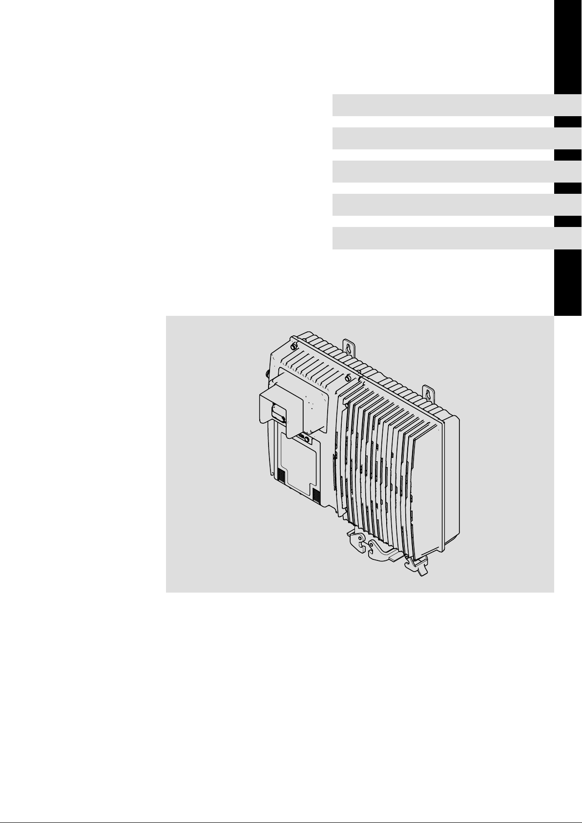
8400 protec 0.75 ... 7.5 kW
E84Dxxxxxxx HighLine/StateLine/EMS
Decentralised frequency inverter
Page 2

0Fig. 0Tab. 0
Page 3

Contents i
1 About this documentation 7. . . . . . . . . . . . . . . . . . . . . . . . . . . . . . . . . . . . . . . . . . . . . . . . . .
1.1 Document history 7. . . . . . . . . . . . . . . . . . . . . . . . . . . . . . . . . . . . . . . . . . . . . . . . . . . .
1.2 Conventions used 8. . . . . . . . . . . . . . . . . . . . . . . . . . . . . . . . . . . . . . . . . . . . . . . . . . . .
1.3 Terms and abbreviations used 9. . . . . . . . . . . . . . . . . . . . . . . . . . . . . . . . . . . . . . . . . .
1.4 Notes used 12. . . . . . . . . . . . . . . . . . . . . . . . . . . . . . . . . . . . . . . . . . . . . . . . . . . . . . . . . .
2 Safety instructions 13. . . . . . . . . . . . . . . . . . . . . . . . . . . . . . . . . . . . . . . . . . . . . . . . . . . . . . . . .
2.1 General safety and application notes for Lenze controllers 13. . . . . . . . . . . . . . . . . .
2.2 General safety and application instructions for Lenze motors 16. . . . . . . . . . . . . . . .
2.3 Residual hazards 19. . . . . . . . . . . . . . . . . . . . . . . . . . . . . . . . . . . . . . . . . . . . . . . . . . . . .
3 Product description 20. . . . . . . . . . . . . . . . . . . . . . . . . . . . . . . . . . . . . . . . . . . . . . . . . . . . . . . .
3.1 Device features 20. . . . . . . . . . . . . . . . . . . . . . . . . . . . . . . . . . . . . . . . . . . . . . . . . . . . . .
3.2 Identification 21. . . . . . . . . . . . . . . . . . . . . . . . . . . . . . . . . . . . . . . . . . . . . . . . . . . . . . . .
3.3 Type code 22. . . . . . . . . . . . . . . . . . . . . . . . . . . . . . . . . . . . . . . . . . . . . . . . . . . . . . . . . .
3.4 Overview of standard devices 25. . . . . . . . . . . . . . . . . . . . . . . . . . . . . . . . . . . . . . . . . .
3.5 Communication 27. . . . . . . . . . . . . . . . . . . . . . . . . . . . . . . . . . . . . . . . . . . . . . . . . . . . . .
3.5.1 CAN port 27. . . . . . . . . . . . . . . . . . . . . . . . . . . . . . . . . . . . . . . . . . . . . . . . . . . .
3.5.2 Infrared remote control receiver 28. . . . . . . . . . . . . . . . . . . . . . . . . . . . . . . . .
3.5.3 Extensions in EMS version 28. . . . . . . . . . . . . . . . . . . . . . . . . . . . . . . . . . . . . .
3.5.4 Infrared interface 29. . . . . . . . . . . . . . . . . . . . . . . . . . . . . . . . . . . . . . . . . . . . .
3.6 Concepts for the mains connection 30. . . . . . . . . . . . . . . . . . . . . . . . . . . . . . . . . . . . . .
3.6.1 Concepts for the connection of individual axes 30. . . . . . . . . . . . . . . . . . . .
3.6.2 Concepts for the connection of the power bus 32. . . . . . . . . . . . . . . . . . . . .
3.7 EMS mains connection concepts 35. . . . . . . . . . . . . . . . . . . . . . . . . . . . . . . . . . . . . . . .
3.7.1 Half wave (coded) 35. . . . . . . . . . . . . . . . . . . . . . . . . . . . . . . . . . . . . . . . . . . . .
3.7.2 Power wave 36. . . . . . . . . . . . . . . . . . . . . . . . . . . . . . . . . . . . . . . . . . . . . . . . . .
3.7.3 DECA bus 37. . . . . . . . . . . . . . . . . . . . . . . . . . . . . . . . . . . . . . . . . . . . . . . . . . . .
3.7.4 Inductive 38. . . . . . . . . . . . . . . . . . . . . . . . . . . . . . . . . . . . . . . . . . . . . . . . . . . .
4 Technical data 39. . . . . . . . . . . . . . . . . . . . . . . . . . . . . . . . . . . . . . . . . . . . . . . . . . . . . . . . . . . .
4.1 General data and operating conditions 39. . . . . . . . . . . . . . . . . . . . . . . . . . . . . . . . .
4.2 Rated data 46. . . . . . . . . . . . . . . . . . . . . . . . . . . . . . . . . . . . . . . . . . . . . . . . . . . . . . . . . .
4.2.1 Overview 46. . . . . . . . . . . . . . . . . . . . . . . . . . . . . . . . . . . . . . . . . . . . . . . . . . . .
4.2.2 Operation at rated mains voltage 400 V 48. . . . . . . . . . . . . . . . . . . . . . . . . .
4.2.3 Operation at a rated mains voltage of 500 V 51. . . . . . . . . . . . . . . . . . . . . .
4.3 Current characteristics 54. . . . . . . . . . . . . . . . . . . . . . . . . . . . . . . . . . . . . . . . . . . . . . . .
4.4 Overcurrent operation 56. . . . . . . . . . . . . . . . . . . . . . . . . . . . . . . . . . . . . . . . . . . . . . . .
4.5 Terminal description 59. . . . . . . . . . . . . . . . . . . . . . . . . . . . . . . . . . . . . . . . . . . . . . . . . .
EDS84DPS424 EN 5.0
3
Page 4

Contentsi
4.6 Supply concept of control voltage 61. . . . . . . . . . . . . . . . . . . . . . . . . . . . . . . . . . . . . . .
4.6.1 Internal 24 V supply voltage 61. . . . . . . . . . . . . . . . . . . . . . . . . . . . . . . . . . . .
4.6.2 External supply voltage 24 V 62. . . . . . . . . . . . . . . . . . . . . . . . . . . . . . . . . . . .
4.7 Control terminals 64. . . . . . . . . . . . . . . . . . . . . . . . . . . . . . . . . . . . . . . . . . . . . . . . . . . . .
4.7.1 Digital inputs 64. . . . . . . . . . . . . . . . . . . . . . . . . . . . . . . . . . . . . . . . . . . . . . . .
4.7.2 Digital outputs 65. . . . . . . . . . . . . . . . . . . . . . . . . . . . . . . . . . . . . . . . . . . . . . .
4.7.3 Analog inputs 66. . . . . . . . . . . . . . . . . . . . . . . . . . . . . . . . . . . . . . . . . . . . . . . .
4.7.4 Synchronous serial interface (SSI) 66. . . . . . . . . . . . . . . . . . . . . . . . . . . . . . . .
4.7.5 Remote control (IrRC) 66. . . . . . . . . . . . . . . . . . . . . . . . . . . . . . . . . . . . . . . . . .
4.7.6 Interfaces of the EMS version 67. . . . . . . . . . . . . . . . . . . . . . . . . . . . . . . . . . .
4.7.7 Motor holding brake connection 68. . . . . . . . . . . . . . . . . . . . . . . . . . . . . . . .
5 Mechanical installation 70. . . . . . . . . . . . . . . . . . . . . . . . . . . . . . . . . . . . . . . . . . . . . . . . . . . . .
5.1 Important notes 70. . . . . . . . . . . . . . . . . . . . . . . . . . . . . . . . . . . . . . . . . . . . . . . . . . . . . .
5.2 Dimensions 71. . . . . . . . . . . . . . . . . . . . . . . . . . . . . . . . . . . . . . . . . . . . . . . . . . . . . . . . . .
5.3 Mounting clearance 72. . . . . . . . . . . . . . . . . . . . . . . . . . . . . . . . . . . . . . . . . . . . . . . . . . .
6 Electrical installation − HighLine/StateLine version 73. . . . . . . . . . . . . . . . . . . . . . . . . . . . . .
6.1 Important notes 73. . . . . . . . . . . . . . . . . . . . . . . . . . . . . . . . . . . . . . . . . . . . . . . . . . . . . .
6.1.1 Electrical isolation 76. . . . . . . . . . . . . . . . . . . . . . . . . . . . . . . . . . . . . . . . . . . .
6.1.2 Device protection 76. . . . . . . . . . . . . . . . . . . . . . . . . . . . . . . . . . . . . . . . . . . . .
6.1.3 Maximum motor cable length 77. . . . . . . . . . . . . . . . . . . . . . . . . . . . . . . . . .
6.1.4 Motor protection 77. . . . . . . . . . . . . . . . . . . . . . . . . . . . . . . . . . . . . . . . . . . . .
6.2 Safety instructions for the installation according to UL or UR 78. . . . . . . . . . . . . . . .
6.3 Safety instructions for the installation according to UL or UR 79. . . . . . . . . . . . . . . .
6.4 Installation according to EMC (installation of a CE−typical drive system) 80. . . . . . .
6.4.1 Shielding 80. . . . . . . . . . . . . . . . . . . . . . . . . . . . . . . . . . . . . . . . . . . . . . . . . . . .
6.4.2 Motor cable 81. . . . . . . . . . . . . . . . . . . . . . . . . . . . . . . . . . . . . . . . . . . . . . . . . .
6.4.3 Control cables 82. . . . . . . . . . . . . . . . . . . . . . . . . . . . . . . . . . . . . . . . . . . . . . . .
6.4.4 Wiring 83. . . . . . . . . . . . . . . . . . . . . . . . . . . . . . . . . . . . . . . . . . . . . . . . . . . . . .
6.4.5 Detecting and eliminating EMC interferences 85. . . . . . . . . . . . . . . . . . . . .
6.5 Devices in a power range of 0.75 ... 7.5 kW (3/PE AC 400 V) 86. . . . . . . . . . . . . . . . . .
6.5.1 Example circuits 86. . . . . . . . . . . . . . . . . . . . . . . . . . . . . . . . . . . . . . . . . . . . . .
6.5.2 Terminal assignment of the power connections 87. . . . . . . . . . . . . . . . . . .
6.6 Control terminals 92. . . . . . . . . . . . . . . . . . . . . . . . . . . . . . . . . . . . . . . . . . . . . . . . . . . . .
6.6.1 Diagnostics 92. . . . . . . . . . . . . . . . . . . . . . . . . . . . . . . . . . . . . . . . . . . . . . . . . .
6.6.2 Analog input 93. . . . . . . . . . . . . . . . . . . . . . . . . . . . . . . . . . . . . . . . . . . . . . . . .
6.6.3 Digital inputs and outputs 95. . . . . . . . . . . . . . . . . . . . . . . . . . . . . . . . . . . . .
6.6.4 Synchronous serial interface (SSI) 98. . . . . . . . . . . . . . . . . . . . . . . . . . . . . . . .
4
EDS84DPS424 EN 5.0
Page 5

Contents i
6.7 Communication 99. . . . . . . . . . . . . . . . . . . . . . . . . . . . . . . . . . . . . . . . . . . . . . . . . . . . . .
6.7.1 PROFINET® / EtherNet/IP 100. . . . . . . . . . . . . . . . . . . . . . . . . . . . . . . . . . . . .
6.7.2 PROFIBUS® 100. . . . . . . . . . . . . . . . . . . . . . . . . . . . . . . . . . . . . . . . . . . . . . . . . .
6.7.3 CANopen® 101. . . . . . . . . . . . . . . . . . . . . . . . . . . . . . . . . . . . . . . . . . . . . . . . . . .
6.7.4 CAN on board 101. . . . . . . . . . . . . . . . . . . . . . . . . . . . . . . . . . . . . . . . . . . . . . . .
6.8 Safety engineering 102. . . . . . . . . . . . . . . . . . . . . . . . . . . . . . . . . . . . . . . . . . . . . . . . . . .
7 Electrical installation − EMS version 105. . . . . . . . . . . . . . . . . . . . . . . . . . . . . . . . . . . . . . . . . . .
7.1 Important notes 105. . . . . . . . . . . . . . . . . . . . . . . . . . . . . . . . . . . . . . . . . . . . . . . . . . . . . .
7.1.1 Electrical isolation 108. . . . . . . . . . . . . . . . . . . . . . . . . . . . . . . . . . . . . . . . . . . .
7.1.2 Device protection 108. . . . . . . . . . . . . . . . . . . . . . . . . . . . . . . . . . . . . . . . . . . . .
7.1.3 Maximum motor cable length 109. . . . . . . . . . . . . . . . . . . . . . . . . . . . . . . . . .
7.1.4 Motor protection 109. . . . . . . . . . . . . . . . . . . . . . . . . . . . . . . . . . . . . . . . . . . . .
7.2 Safety instructions for the installation according to UL or UR 110. . . . . . . . . . . . . . . .
7.3 Safety instructions for the installation according to UL or UR 111. . . . . . . . . . . . . . . .
7.4 Installation according to EMC (installation of a CE−typical drive system) 112. . . . . . .
7.4.1 Shielding 112. . . . . . . . . . . . . . . . . . . . . . . . . . . . . . . . . . . . . . . . . . . . . . . . . . . .
7.4.2 Motor cable 113. . . . . . . . . . . . . . . . . . . . . . . . . . . . . . . . . . . . . . . . . . . . . . . . . .
7.4.3 Control cables 114. . . . . . . . . . . . . . . . . . . . . . . . . . . . . . . . . . . . . . . . . . . . . . . .
7.4.4 Wiring 115. . . . . . . . . . . . . . . . . . . . . . . . . . . . . . . . . . . . . . . . . . . . . . . . . . . . . .
7.4.5 Detecting and eliminating EMC interferences 117. . . . . . . . . . . . . . . . . . . . .
7.5 Devices in a power range of 0.75 ... 4 kW (3/PE AC 400 V) 118. . . . . . . . . . . . . . . . . . . .
7.5.1 Example circuits 118. . . . . . . . . . . . . . . . . . . . . . . . . . . . . . . . . . . . . . . . . . . . . .
7.5.2 Terminal assignment of the power connections 121. . . . . . . . . . . . . . . . . . .
7.6 Control terminals 127. . . . . . . . . . . . . . . . . . . . . . . . . . . . . . . . . . . . . . . . . . . . . . . . . . . . .
7.6.1 Diagnostics 127. . . . . . . . . . . . . . . . . . . . . . . . . . . . . . . . . . . . . . . . . . . . . . . . . .
7.6.2 Digital inputs and outputs 128. . . . . . . . . . . . . . . . . . . . . . . . . . . . . . . . . . . . .
7.6.3 Synchronous serial interface (SSI) 132. . . . . . . . . . . . . . . . . . . . . . . . . . . . . . . .
7.6.4 Interfaces RS485/422 PLC 133. . . . . . . . . . . . . . . . . . . . . . . . . . . . . . . . . . . . . .
7.6.5 Interfaces RS485 PLC 134. . . . . . . . . . . . . . . . . . . . . . . . . . . . . . . . . . . . . . . . . .
7.6.6 Interfaces RS422 PLC 135. . . . . . . . . . . . . . . . . . . . . . . . . . . . . . . . . . . . . . . . . .
7.7 Communication 136. . . . . . . . . . . . . . . . . . . . . . . . . . . . . . . . . . . . . . . . . . . . . . . . . . . . . .
7.7.1 CANopen 137. . . . . . . . . . . . . . . . . . . . . . . . . . . . . . . . . . . . . . . . . . . . . . . . . . . .
7.7.2 CANopen master PLC 137. . . . . . . . . . . . . . . . . . . . . . . . . . . . . . . . . . . . . . . . . .
8 Commissioning 138. . . . . . . . . . . . . . . . . . . . . . . . . . . . . . . . . . . . . . . . . . . . . . . . . . . . . . . . . . .
8.1 Before switching on 139. . . . . . . . . . . . . . . . . . . . . . . . . . . . . . . . . . . . . . . . . . . . . . . . . .
8.2 Preparing the commissioning procedure 140. . . . . . . . . . . . . . . . . . . . . . . . . . . . . . . . .
8.3 Quick commissioning 143. . . . . . . . . . . . . . . . . . . . . . . . . . . . . . . . . . . . . . . . . . . . . . . . .
8.3.1 Keypad control 144. . . . . . . . . . . . . . . . . . . . . . . . . . . . . . . . . . . . . . . . . . . . . . .
8.3.2 Terminal control 146. . . . . . . . . . . . . . . . . . . . . . . . . . . . . . . . . . . . . . . . . . . . . .
EDS84DPS424 EN 5.0
5
Page 6

Contentsi
9 Braking operation 148. . . . . . . . . . . . . . . . . . . . . . . . . . . . . . . . . . . . . . . . . . . . . . . . . . . . . . . . .
9.1 Braking operation without additional measures 148. . . . . . . . . . . . . . . . . . . . . . . . . . .
9.2 Braking operation with external brake resistor 151. . . . . . . . . . . . . . . . . . . . . . . . . . . .
9.2.1 Selection of the brake resistors 152. . . . . . . . . . . . . . . . . . . . . . . . . . . . . . . . . .
9.2.2 Wiring of brake resistor 153. . . . . . . . . . . . . . . . . . . . . . . . . . . . . . . . . . . . . . . .
9.3 Operation with spring−applied brake 156. . . . . . . . . . . . . . . . . . . . . . . . . . . . . . . . . . . .
9.3.1 Introduction 156. . . . . . . . . . . . . . . . . . . . . . . . . . . . . . . . . . . . . . . . . . . . . . . . .
9.3.2 Wiring 158. . . . . . . . . . . . . . . . . . . . . . . . . . . . . . . . . . . . . . . . . . . . . . . . . . . . . .
10 Diagnostics 159. . . . . . . . . . . . . . . . . . . . . . . . . . . . . . . . . . . . . . . . . . . . . . . . . . . . . . . . . . . . . . .
10.1 Display of operating data, diagnostics 159. . . . . . . . . . . . . . . . . . . . . . . . . . . . . . . . . . .
10.1.1 Status display via controller LEDs 159. . . . . . . . . . . . . . . . . . . . . . . . . . . . . . . .
10.1.2 Extensions in EMS version 161. . . . . . . . . . . . . . . . . . . . . . . . . . . . . . . . . . . . . .
10.1.3 Status display of the safety system via LEDs at the controller 162. . . . . . . .
10.1.4 Drive diagnostics via the integrated display 165. . . . . . . . . . . . . . . . . . . . . . .
10.1.5 Drive diagnostics 170. . . . . . . . . . . . . . . . . . . . . . . . . . . . . . . . . . . . . . . . . . . . .
11 Safety engineering 172. . . . . . . . . . . . . . . . . . . . . . . . . . . . . . . . . . . . . . . . . . . . . . . . . . . . . . . .
11.1 Introduction 172. . . . . . . . . . . . . . . . . . . . . . . . . . . . . . . . . . . . . . . . . . . . . . . . . . . . . . . . .
11.2 Important notes 173. . . . . . . . . . . . . . . . . . . . . . . . . . . . . . . . . . . . . . . . . . . . . . . . . . . . . .
11.3 Overview of safety options 174. . . . . . . . . . . . . . . . . . . . . . . . . . . . . . . . . . . . . . . . . . . .
12 Accessories (overview) 176. . . . . . . . . . . . . . . . . . . . . . . . . . . . . . . . . . . . . . . . . . . . . . . . . . . . .
12.1 Overview 176. . . . . . . . . . . . . . . . . . . . . . . . . . . . . . . . . . . . . . . . . . . . . . . . . . . . . . . . . . . .
12.2 System cables 177. . . . . . . . . . . . . . . . . . . . . . . . . . . . . . . . . . . . . . . . . . . . . . . . . . . . . . . .
12.2.1 Motor cable 177. . . . . . . . . . . . . . . . . . . . . . . . . . . . . . . . . . . . . . . . . . . . . . . . . .
12.2.2 Incremental HTL encoder 179. . . . . . . . . . . . . . . . . . . . . . . . . . . . . . . . . . . . . . .
12.2.3 Connection of external brake resistor 180. . . . . . . . . . . . . . . . . . . . . . . . . . . .
12.2.4 Connection of safety sensors and actuators 181. . . . . . . . . . . . . . . . . . . . . . .
12.3 Memory module 182. . . . . . . . . . . . . . . . . . . . . . . . . . . . . . . . . . . . . . . . . . . . . . . . . . . . .
12.3.1 E84AYM10S 182. . . . . . . . . . . . . . . . . . . . . . . . . . . . . . . . . . . . . . . . . . . . . . . . . .
12.3.2 E84AYM30S 183. . . . . . . . . . . . . . . . . . . . . . . . . . . . . . . . . . . . . . . . . . . . . . . . . .
12.4 Diagnosis terminal 184. . . . . . . . . . . . . . . . . . . . . . . . . . . . . . . . . . . . . . . . . . . . . . . . . . .
12.5 Infrared remote control (IrRC) 185. . . . . . . . . . . . . . . . . . . . . . . . . . . . . . . . . . . . . . . . . .
12.6 External brake resistors 186. . . . . . . . . . . . . . . . . . . . . . . . . . . . . . . . . . . . . . . . . . . . . . .
12.7 Power supply units 187. . . . . . . . . . . . . . . . . . . . . . . . . . . . . . . . . . . . . . . . . . . . . . . . . . .
12.8 EMS accessories 188. . . . . . . . . . . . . . . . . . . . . . . . . . . . . . . . . . . . . . . . . . . . . . . . . . . . . .
13 Appendix 189. . . . . . . . . . . . . . . . . . . . . . . . . . . . . . . . . . . . . . . . . . . . . . . . . . . . . . . . . . . . . . . .
13.1 Declarations and certificates 189. . . . . . . . . . . . . . . . . . . . . . . . . . . . . . . . . . . . . . . . . . .
13.2 Total index 195. . . . . . . . . . . . . . . . . . . . . . . . . . . . . . . . . . . . . . . . . . . . . . . . . . . . . . . . . .
6
EDS84DPS424 EN 5.0
Page 7

1 About this documentation
Contents
The hardware manual contains the complete information on the intended use of the 8400
protec controllers in the StateLine and HighLine versions.
Validity
These instructions apply to decentralised 8400 protec frequency inverters with the
following type designation:
Type designation From HW From SW
E84DSxxx... (StateLine) VA 01.01
E84DHxxx... (HighLine) VA 02.02
E84DDxxx... (EMS) VA 01.00
E84DExxx... (EMS) VA 01.00
E84DFxxx... (EMS) VA 01.00
E84DLxxx... (EMS) VA 01.00
E84DPxxx... (EMS) VA 01.00
About this documentation
Document history
1
Further information on the type code can be obtained from the "Product description"
chapter.
Target group
This hardware manual is intended for all persons who design, install, commission, and set
8400 protec controllers.
Tip!
Information and auxiliary devices related to the Lenze products can be found
in the download area at
http://www.Lenze.com
1.1 Document history
Material number Version Description
.M^h 5.0 10/2013 TD15 Additions by UL
13428102 4.1 04/2013 TD15 Expansion up to 7.5 kW and corrections
13398992 3.0 05/2012 TD15 Additions and corrections
13384749 2.0 06/2011 TD15 Extended by EMS version
13368848 1.1 05/2011 TD15 General revision
13337296 1.0 04/2010 TD15 First edition
EDS84DPS424 EN 5.0
7
Page 8

1
About this documentation
Conventions used
1.2 Conventions used
This documentation uses the following conventions to distinguish between different
types of information:
Spelling of numbers
Decimal separator
Warnings
UL warnings
UR warnings
Text
Program name » « PC software
Icons
Page reference Reference to another page with additional
Documentation reference Reference to another documentation with
Point In general, the decimal point is used.
For instance: 1234.56
Given in English and French
For example: »Engineer«, »Global Drive
Control« (GDC)
information
For instance: 16 = see page 16
additional information
For example: EDKxxx = see
documentation EDKxxx
8
EDS84DPS424 EN 5.0
Page 9

About this documentation
Terms and abbreviations used
1
1.3 Terms and abbreviations used
Axis, drive Lenze controller combined with a motor or geared motor and other
Basic insulation Insulation providing basic protection against hazardous shock
Controller Any frequency inverter, servo inverter, or DC speed controller
Device size Used as generic term for a group of devices which have the same
Double insulation Basic insulation and additional insulation
Functional insulation Insulation ensuring perfect operation
Holding brake See motor holding brake
Motor holding brake The motor holding brake serves to statically hold e.g. a position during
Reinforced insulation Uniform insulation system, same protection as double insulation
Spring−applied brake Design type of a (motor) holding brake
Standard device Used as generic term when actions and features are described which
EMS Electrified Monorail System, e.g. monorail overhead conveyors,
Half wave (coded) Process for transmitting control signals via contact conductor
Power wave Process for transmitting control signals with mains voltage
DECA BUS Process for transmitting control signals via rail bus
PLC Programmable logic controller, compatible with IEC 61131
IrRC Infrared remote control
IrDA Infrared data interface
Cxxxxx/y Subcode y of code Cxxxx
Lenze drive components
currents
dimensions (depth, height and width) but different power ratings.
the downtimes of a robot, travelling, synchronous, or hoist drive.
(electromechanically released, spring−applied operation)
are very similar or the same for different versions or device sizes, e.g.
mechanical installation or
power terminals
automated guided vehicle systems
Control bar and message bar, also with coding
(e.g. C0410/3 = subcode 3 of code C0410)
EDS84DPS424 EN 5.0
Xk/y Terminal y on terminal strip Xk (e.g. X3/28 = terminal 28 on terminal
strip X3)
9
Page 10

1
About this documentation
Terms and abbreviations used
AC AC current or AC voltage
DC DC current or DC voltage
V
[V]
LR
[V]
U
DC
[V]
U
M
I
[A]
LR
[A]
I
aR
I
[A]
aM
[mA]
I
PE
[kW]
P
R
P
[W]
V
[kW]
P
DC
S
[kVA]
R
[Nm]
M
R
[Hz]
f
max
L [mH] Inductance
R [] Resistor
Rated mains voltage
DC voltage
Output voltage / voltage at the motor terminals
Rated mains current
Rated output current
Maximum output current
Discharge current
Rated motor power
Inverter power loss
Power at the DC voltage end
Apparent output power of the controller
Rated torque
Maximum frequency
DIN Deutsches Institut für Normung
EMC Electromagnetic compatibility
EN European standard
IEC International Electrotechnical Commission
IP International Protection Code
NEMA National Electrical Manufacturers Association
VDE Verband deutscher Elektrotechniker
CE Communauté Européene
UL Underwriters Laboratories
10
EDS84DPS424 EN 5.0
Page 11

About this documentation
Terms and abbreviations used
Terms and abbreviations of the safety system
Abbreviation Meaning
24O 24 V voltage supply for non−safe monitoring
Cat. Category according to EN 954−1 (valid until 30 November 2009)
DO Non−safe feedback output
F−PLC Safety PLC
GSDML File containing device−specific data to establish PROFINET communication
GSE File containing device−specific data to establish PROFIBUS communication
OFF state Signal status of the safety sensors when they are activated or respond
ON state Signal status of the safety sensors during normal operation
Opto supply Optocoupler supply for controlling the drivers
OSSD Output Signal Switching Device, tested signal output
PELV Protective Extra Low Voltage
PL Performance Level according to EN ISO 13849−1
PM P/N switching signal paths
PP P/P switching signal paths
PS PROFIsafe
PWM Pulse Width Modulation
S−Bus Safety bus
SD−In Safe input (Safe Digital Input)
SD−Out Safe output (Safe Digital Output)
SELV Safety Extra Low Voltage
SIA, SIB Safe Input, channel A or B, respectively
SIL Safety Integrity Level according to IEC 61508
SO Integrated safety option
1
Abbreviation Safety function
AIE Error acknowledgement (Acknowledge In Error)
AIS Restart acknowledgement (Acknowledge In Stop)
ES Safe enable switch
OMS Operation Mode Selector
SS1 Safe Stop 1
SSE Safe Stop Emergency
STO Safe Torque Off
Formerly: Safe standstill
EDS84DPS424 EN 5.0
11
Page 12

1
About this documentation
Notes used
1.4 Notes used
The following pictographs and signal words are used in this documentation to indicate
dangers and important information:
Safety instructions
Structure of safety instructions:
Danger!
(characterises the type and severity of danger)
Note
(describes the danger and gives information about how to prevent dangerous
situations)
Pictograph and signal word Meaning
Danger!
Danger!
Stop!
Danger of personal injury through dangerous electrical voltage.
Reference to an imminent danger that may result in death or
serious personal injury if the corresponding measures are not
taken.
Danger of personal injury through a general source of danger.
Reference to an imminent danger that may result in death or
serious personal injury if the corresponding measures are not
taken.
Danger of property damage.
Reference to a possible danger that may result in property
damage if the corresponding measures are not taken.
Application notes
Pictograph and signal word Meaning
Note!
Tip!
Special safety instructions and application notes
Pictograph and signal word Meaning
Warnings!
Warnings!
Important note to ensure troublefree operation
Useful tip for simple handling
Reference to another documentation
Safety note or application note for the operation according to
UL or CSA requirements.
The measures are required to meet the requirements according
to UL or CSA.
12
EDS84DPS424 EN 5.0
Page 13

Safety instructions
General safety and application notes for Lenze controllers
2 Safety instructions
2.1 General safety and application notes for Lenze controllers
(in accordance with Low−Voltage Directive 2006/95/EC)
For your personal safety
Disregarding the following safety measures can lead to severe injury to persons and
damage to material assets:
ƒ Only use the product as directed.
ƒ Never commission the product in the event of visible damage.
ƒ Never commission the product before assembly has been completed.
ƒ Do not carry out any technical changes on the product.
ƒ Only use the accessories approved for the product.
2
ƒ Only use original spare parts from Lenze.
ƒ Observe all regulations for the prevention of accidents, directives and laws
applicable on site.
ƒ Transport, installation, commissioning and maintenance work must only be carried
out by qualified personnel.
– Observe IEC 364 and CENELEC HD 384 or DIN VDE 0100 and IEC report 664 or
DIN VDE 0110 and all national regulations for the prevention of accidents.
– According to this basic safety information, qualified, skilled personnel are persons
who are familiar with the assembly, installation, commissioning, and operation of
the product and who have the qualifications necessary for their occupation.
ƒ Observe all specifications in this documentation.
– This is the condition for safe and trouble−free operation and the achievement of
the specified product features.
– The procedural notes and circuit details described in this documentation are only
proposals. It’s up to the user to check whether they can be transferred to the
particular applications. Lenze Drives GmbH does not accept any liability for the
suitability of the procedures and circuit proposals described.
ƒ Depending on their degree of protection, some parts of the Lenze controllers
(frequency inverters, servo inverters, DC speed controllers) and their accessory
components can be live, moving and rotating during operation. Surfaces can be hot.
– Non−authorised removal of the required cover, inappropriate use, incorrect
installation or operation, creates the risk of severe injury to persons or damage to
material assets.
– For more information, please see the documentation.
EDS84DPS424 EN 5.0
ƒ High amounts of energy are produced in the controller. Therefore it is required to
wear personal protective equipment (body protection, headgear, eye protection, ear
protection, hand guard).
13
Page 14

2
Safety instructions
General safety and application notes for Lenze controllers
Application as directed
Controllers are components which are designed for installation in electrical systems or
machines. They are not to be used as domestic appliances, but only for industrial purposes
according to EN 61000−3−2.
When controllers are installed into machines, commissioning (i.e. starting of the operation
as directed) is prohibited until it is proven that the machine complies with the regulations
of the EC Directive 2006/42/EC (Machinery Directive); EN 60204 must be observed.
Commissioning (i.e. starting of the operation as directed) is only allowed when there is
compliance with the EMC Directive (2004/108/EC).
The controllers meet the requirements of the Low−Voltage Directive 2006/95/EC. The
harmonised standard EN 61800−5−1 applies to the controllers.
The technical data and supply conditions can be obtained from the nameplate and the
documentation. They must be strictly observed.
Warning: Controllers are products which can be installed in drive systems of category C2
according to EN 61800−3. These products can cause radio interferences in residential areas.
In this case, special measures can be necessary.
Transport, storage
Please observe the notes on transport, storage, and appropriate handling.
Observe the climatic conditions according to the technical data.
Installation
The controllers must be installed and cooled according to the instructions given in the
corresponding documentation.
The ambient air must not exceed degree of pollution 2 according to EN 61800−5−1.
Ensure proper handling and avoid excessive mechanical stress. Do not bend any
components and do not change any insulation distances during transport or handling. Do
not touch any electronic components and contacts.
Controllers contain electrostatic sensitive devices which can easily be damaged by
inappropriate handling. Do not damage or destroy any electrical components since this
might endanger your health!
Electrical connection
When working on live controllers, observe the applicable national regulations for the
prevention of accidents (e.g. VBG 4).
The electrical installation must be carried out according to the appropriate regulations
(e.g. cable cross−sections, fuses, PE connection). Additional information can be obtained
from the documentation.
The documentation provides notes on EMC−compliant installation (shielding, earthing,
filter arrangement, and laying of cables). Please also observe these notes when installing
CE−labelled controllers. The manufacturer of the machine or plant is responsible for the
compliance with the required limit values associated with EMC legislation.
Lenze controllers may cause a DC current in the PE conductor. If a residual current device
is used as a protective means in the case of direct or indirect contact with a three−phase
controller, a residual current device of type B must be used on the current supply side of the
controller. If the controller has a single−phase supply, it is also permissible to use a residual
current device of type A. Apart from the use of a residual current device, other protective
measures can also be taken, such as isolation from the environment by double or
reinforced insulation, or separation from the supply system by means of a transformer.
14
EDS84DPS424 EN 5.0
Page 15

Safety instructions
General safety and application notes for Lenze controllers
Operation
If necessary, systems including controllers must be equipped with additional monitoring
and protection devices according to the valid safety regulations (e.g. law on technical
equipment, regulations for the prevention of accidents). The controllers can be adapted to
your application. Please observe the corresponding information given in the
documentation.
After the controller has been disconnected from the supply voltage, all live components
and power terminals must not be touched immediately because capacitors can still be
charged. Please observe the corresponding stickers on the controller.
All protection covers and doors must be shut during operation.
Notes for UL−approved systems with integrated controllers: UL warnings are notes that
only apply to UL systems. The documentation contains special UL notes.
Safety functions
Certain controller versions support safety functions (e.g. "Safe torque off", formerly "Safe
standstill") according to the requirements of the EC Directive "Machinery" 2006/42/EC.
The notes provided in the documentation on drive−based safety must be strictly observed.
2
Maintenance and servicing
The controllers do not require any maintenance if the prescribed operating conditions are
observed.
Disposal
Recycle metal and plastic materials. Ensure professional disposal of assembled PCBs.
The product−specific safety and application notes given in these instructions must be
observed!
EDS84DPS424 EN 5.0
15
Page 16

2
2.2 General safety and application instructions for Lenze motors
Safety instructions
General safety and application instructions for Lenze motors
(According to: Low−Voltage Directive 2006/95/EC)
General
Low−voltage machines have hazardous live and rotating parts and possibly also hot
surfaces.
Synchronous machines induce voltages at open terminals during operation.
All operations concerning transport, connections, commissioning and maintenance must
be carried out by qualified, skilled personnel (EN 50110−1 (VDE 0105−100) and IEC 60364
must be observed). Inappropriate use creates the risk of severe injury to persons and
damage to material assets.
Low−voltage machines may only be operated under the conditions that are indicated in the
section "Application as directed".
The conditions at the place of installation must comply with the data given on the
nameplate and in the documentation.
Application as directed
Low−voltage machines are intended for commercial installations. They comply with the
harmonised standards of the series EN60034 (VDE 0530). Their use in potentially
explosive atmospheres is prohibited unless they are expressly intended for such use
(follow additional instructions).
Low−voltage machines are components for installation into machines as defined in the
Machinery Directive 2006/42/EC. Commissioning is prohibited until the conformity of the
end product with this directive has been established (follow i.a. EN 60204−1)
Low−voltage machines with IP23 protection or less are only intended for outdoor use when
applying special protective features.
The integrated brakes must not be used as safety brakes. It cannot be ruled out that factors
which cannot be influenced, such as oil ingress due to a defective A−side shaft seal, cause
a brake torque reduction.
Transport, storage
Damages must be reported immediately upon receipt to the forwarder; if required,
commissioning must be excluded. Tighten screwed−in ring bolts before transport. They are
designed for the weight of the low−voltage machines, do not apply extra loads. If
necessary, use suitable and adequately dimensioned means of transport (e. g. rope
guides).
Remove transport locking devices before commissioning. Reuse them for further
transport. When storing low−voltage machines, ensure a dry, dust−free and low−vibration
(v
0.2 mm/s) environment (damages while being stored).
eff
16
EDS84DPS424 EN 5.0
Page 17

Safety instructions
General safety and application instructions for Lenze motors
Installation
Ensure an even surface, solid foot and flange mounting and exact alignment if a direct
clutch is connected. Avoid resonances with the rotational frequency and double mains
frequency which may be caused by the assembly. Turn rotor by hand, listen for unusual
slipping noises. Check the direction of rotation when the clutch is not active (observe
section "Electrical connection").
Use appropriate means to mount or remove belt pulleys and clutches (heating) and cover
them with a touch guard. Avoid impermissible belt tensions.
The machines are half−key balanced. The clutch must be half−key balanced, too. The visible
jutting out part of the key must be removed.
If required, provide pipe connections. Designs with shaft end at bottom must be protected
with a cover which prevents the ingress of foreign particles into the fan. Free circulation of
the cooling air must be ensured. The exhaust air − also the exhaust air of other machines
next to the drive system − must not be taken in immediately.
Electrical connection
2
All operations must only be carried out by qualified and skilled personnel on the
low−voltage machine at standstill and deenergised and provided with a safe guard to
prevent an unintentional restart.This also applies to auxiliary circuits (e. g. brake, encoder,
blower).
Check safe isolation from supply!
If the tolerances specified in EN 60034−1; IEC 34 (VDE 0530−1) − voltage ±5 %, frequency
±2 %, waveform, symmetry − are exceeded, more heat will be generated and the
electromagnetic compatibility will be affected.
Observe the data on the nameplate, operating notes, and the connection diagram in the
terminal box.
The connection must ensure a continuous and safe electrical supply (no loose wire ends);
use appropriate cable terminals. The connection to the PE conductor must be safe. The
plug−in connector must be bolt tightly (to stop).
The clearances between blank, live parts and to earth must not fall below 8 mm at
U
550 V, 10 mm at Ur 725 V, 14 mm at Ur 1000 V.
r
The terminal box must be free of foreign particles, dirt and moisture. All unused cable
entries and the box itself must be sealed against dust and water.
EDS84DPS424 EN 5.0
17
Page 18

2
Safety instructions
General safety and application instructions for Lenze motors
Commissioning and operation
Before commissioning after longer storage periods, measure the insulation resistance. In
case of values 1 k per volt of rated voltage, dry winding.
For trial run without output elements, lock the featherkey. Do not deactivate the
protective devices, not even in a trial run.
Check the correct operation of the brake before commissioning low−voltage machines
with brakes.
Integrated thermal detectors do not provide full protection for the machine. If necessary,
limit the maximum current. Parameterise the controller so that the motor will be switched
off with I > I
Vibrational severities v
if the clutch is activated.
If deviations from normal operation occur, e.g. increased temperatures, noises, vibrations,
find the cause and, if required, contact the manufacturer. In case of doubt, switch off the
low−voltage machine.
after a few seconds of operation. especially at the risk of blocking.
r
3.5 mm/s (Pr 15 kW) or 4.5 mm/s (Pr > 15 kW) are acceptable
eff
If the machine is exposed to dirt, clean the air channels regularly.
Shaft sealing rings and roller bearings have a limited service life.
Regrease bearings with relubricating devices while the low−voltage machine is running.
Only use the grease recommended by the manufacturer. If the grease drain holes are
sealed with a plug, (IP54 drive end; IP23 drive and non−drive end), remove plug before
commissioning. Seal bore holes with grease. Replace prelubricated bearings (2Z bearing)
after approx. 10,000 h − 20,000 h, at the latest however after 3 − 4 years.
The product−specific safety and application notes given in these instructions must be
observed!
18
EDS84DPS424 EN 5.0
Page 19

2.3 Residual hazards
Protection of persons
ƒ Before working on the controller, check if no voltage is applied to the power
terminals.
ƒ The operating temperature of the heatsink at the controller is very high. Skin
contact with the heatsink causes burns. If required, provide for protective covers.
ƒ Before working on the controller, check if no voltage is applied to the power
terminals because
– depending on the device − the power terminals U, V, W, Rb1, and Rb2 remain live
for at least 3 ... 20 minutes after disconnecting the mains.
– the power terminals L1, L2, L3; U, V, W, Rb1, and Rb2 remain live when the motor is
stopped.
Device protection
ƒ Frequent switching on of the mains voltage (e.g. inching mode via mains contactor)
may overload or destroy the controller.
Safety instructions
Residual hazards
2
Motor protection
ƒ Frequent switching on may overheat the connected motor.
ƒ Use PTC thermistors or thermostats with PTC characteristics to monitor the motor.
ƒ Depending on the controller settings, the connected motor can be overheated by:
– For instance, longer DC−braking operations.
– Longer operation of self−ventilated motors at low speed.
Protection of the machine/system
ƒ Drives can reach dangerous overspeeds (e.g. setting of high output frequencies in
connection with motors and machines unsuitable for such conditions):
– The controllers do not offer any protection against such operating conditions. Use
additional components for this purpose.
ƒ Switch contactors in the motor cable only if the controller is inhibited.
When switching contactors in the motor cable while the controller is enabled, you can
activate monitoring functions of the controller. If no monitoring function is activated,
switching is permissible.
ƒ All unused connectors must be closed with protection covers or blanking plugs.
EDS84DPS424 EN 5.0
19
Page 20

3
Product description
Device features
3 Product description
3.1 Device features
Decentralised 8400 protec frequency inverter Version
Features HighLine StateLine EMS
Power range 0.75 ... 7.5 kW 0.75 ... 4 kW 0.75 ... 7.5 kW
Mounting type Wall−mounted device
Brake management Control of a mechanical motor holding brake
24 V supply
Internal (depending on mains voltage)
24 V buffer voltage possible
(for maintaining the control functionality
in the case of mains failure)
Interfaces
Digital inputs, 6 6 14
can be configured as outputs 2 2 2 or 4
Analog inputs
or optionally synchronous serial interface
(SSI)
Optional: RS485 or/and RS422 − − 2 x RS485
Remote control, infrared (IrRC) (from SW V12) −
Data interface, infrared (IrDA) − −
Optional:
Drive−based safety Safety option (SO) 10, 20 or 30 −
Operation in generator mode Internal or external brake resistor
Control element
Operation
200 % overload current for 3 s
S ramps for jerk−free acceleration and
deceleration
Protection against restart for cyclic mains
switching
Technology applications
Speed actuating drive
Switch−off positioning
Absolute positioning −
Table positioning −
EMS−specific communication
Half wave − −
Half wave coded − −
Power wave − −
DECA BUS − −
Inductive energy transmission − −
PLC functionality − −
−
1
1
Various service switches
−
2 x RS422
1 x RS485 / RS422
each
Rocker switch
1
20
EDS84DPS424 EN 5.0
Page 21
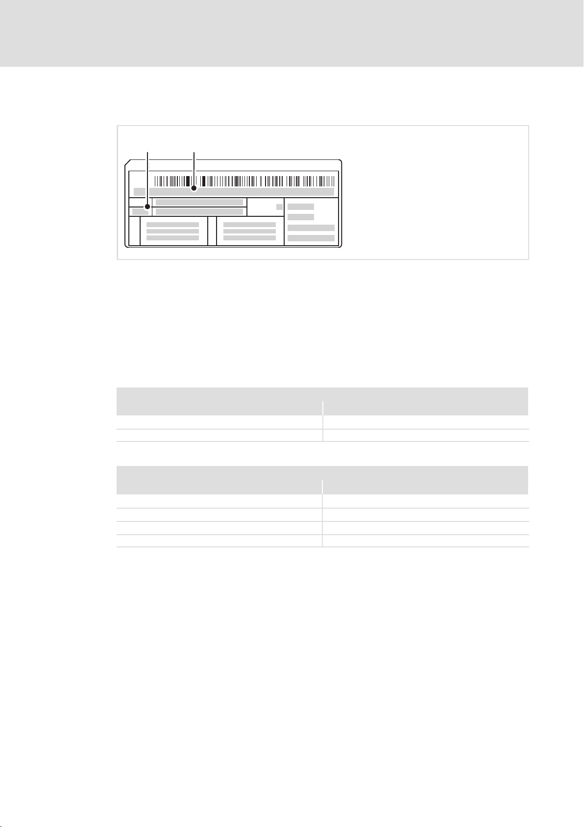
3.2 Identification
Product description
Identification
3
Inverter Drives 8400 protec
Type:
SW:
Input
IP
Q
Output
Type designation
Version
L
C
E84DWAK001
Note
The type designation serves to identify detailed device properties with the following type
code. The listing of the type code, features, and device properties does not consider any
limitations of possible combinations.
In the HighLine and StateLine versions, certain combinations are not possible:
Possible ...
either or
Safety option 30 < > CAN on board
Analog input
< > SSI
Impossible ...
with/in
PROFIBUS < > Push−pull
CANopen < > Push−pull
SSI < > StateLine
EtherNet/IP < > Safety option 20 or 30
EDS84DPS424 EN 5.0
21
Page 22

3
Product description
Type code
3.3 Type code
StateLine, HighLine
Product range
Inverter Drives 8400 protec
Version
S = StateLine
H = HighLine
Connection system for mains and 24 V supply
M = 2 hybrid plugs, type Q4/2
P = 1 hybrid plug, type Q4/2
H = circular connector Molex (Brad Mini−Change)
Motor holding brake control
(with connection system for motor)
"Fast switch":
B = plug type Modular
Integrated half−wave brake rectifier:
F = plug type Q8/0
"Cold brake":
C = plug type Q8/0
Series
C = 24 V internal
Power, e.g.
152 = 15 x 10
Voltage class
4 = 400/500 V, 3/PE AC
Communication (fieldbus)
C = CANopen
P = PROFIBUS®
R = PROFINET®
G = EtherNet/IP
Configuration of input and output range
see table "Possible combinations", 27
Extension module
S = None
Drive−based safety
N = none
J = safety option 10
K = safety option 20
L = safety option 30
Control element
N = none
C = service switch with protective function
W = service switch with operating unit
Brake resistor
N = none
R = internal
E = external connection option
2
W = 1.5 kW
E84D x x x x xxx x x x x x x x
22
EDS84DPS424 EN 5.0
Page 23

Product description
EMS version
E84D x x x x xxx x x x x x x x
Product range
Inverter Drives 8400 protec EMS
Special communication version for
monorail overhead conveyor applications
E = half wave
L = coded half wave
P = power wave
D = DECA bus
F = inductive system
Connection system for mains and 24−V supply of the
brake control in case of inductive systems
M = 2 hybrid plugs, type Q4/2
P = 1 hybrid plug, type Q4/2
Motor holding brake control
(with connection system for motor)
"Fast switch":
B = plug type Modular
Integrated half−wave brake rectifier:
K = plug type Q8/0
H = plug type Han 10E
24 V DC:
V = plug type Q8/0 (for version F only)
Series
for half wave version:
D = half wave 400 V AC / reference phase L1 // 24 V DC
internal
E = half wave 400 V AC / reference phase L3 // 24 V DC
internal
for coded half wave version:
F = half wave 230 V AC / reference phase L1 // 24V DC
internal
G = half wave 230 V AC / reference phase L3 // 24V DC
internal
for power wave version or DECA bus:
E = half wave 400 V AC / reference phase L3 // 24 V DC
internal
for inductive system version:
C = 24 V DC internal
Power, e.g.
152 = 15 x 10
Voltage class
4 = 400/500 V, 3/PE AC
Communication (fieldbus)
C = CANopen
Configuration of input and output range
1 = CANopen and analog input via M12 plug
5 = CANopen and SSI via M12 plug
Extension module
B = digital I/O, CAN, 2 x RS485
C = digital I/O, CAN, RS485, RS422
D = digital I/O, CAN, 2 x RS422
Drive−based safety
N = none
2
W = 1.5 kW
3
Type code
EDS84DPS424 EN 5.0
23
Page 24

3
Product description
Type code
xxxxxxxxxxxxxxE84D
Control element
N = none
C = service switch with protective function
R = rocker switch for EMS (without mains disconnection)
Brake resistor
N = none
R = internal
E = external connection option
24
EDS84DPS424 EN 5.0
Page 25
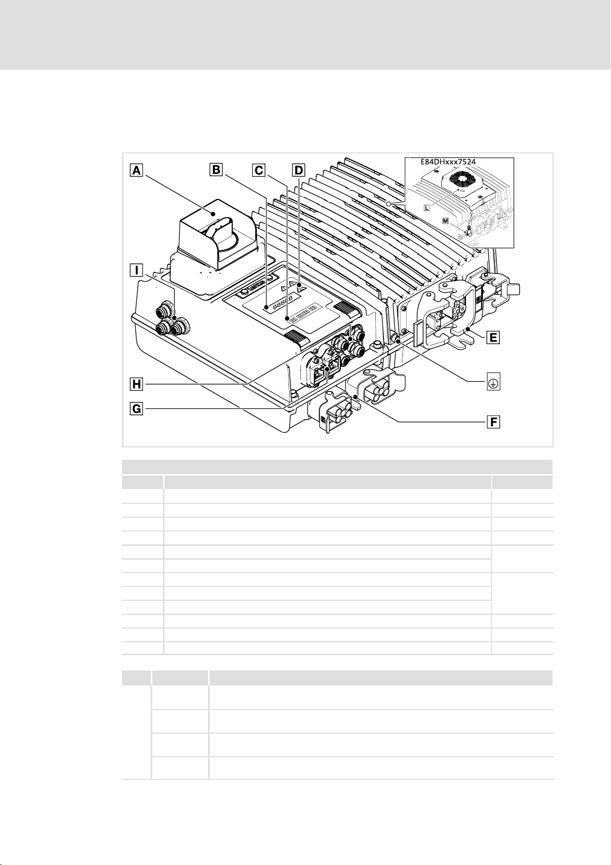
3.4 Overview of standard devices
StateLine, HighLine
Product description
Overview of standard devices
3
E84DWGA010
Control elements and overview of connections
Pos. Description/function Page(s)
Control element, various versions, optional 22
Display for values and messages, 5 characters 165
LED status display 159
Warning symbols See below
Motor and brake resistor connections
Connections for mains and 24 V supply voltage
Fieldbus connections
Input and output connections
Connections for safety system and/or CAN on board
PE connections, M6 thread −
only E84DHxxx7524: External fan
Operating voltage for the external fan −
Pos. Icon Description
Long discharge time: All power terminals remain live for up to 3 minutes after mains
disconnection!
High discharge current: Carry out fixed installation and PE connection according to
EN 61800−5−1!
Electrostatic sensitive devices: Before working on the device, the personnel must be free
of electrostatic charge!
Hot surface: Risk of burns! Hot surfaces should not be touched without wearing
protective gloves.
From 87
From 64
EDS84DPS424 EN 5.0
25
Page 26
3
Product description
Overview of standard devices
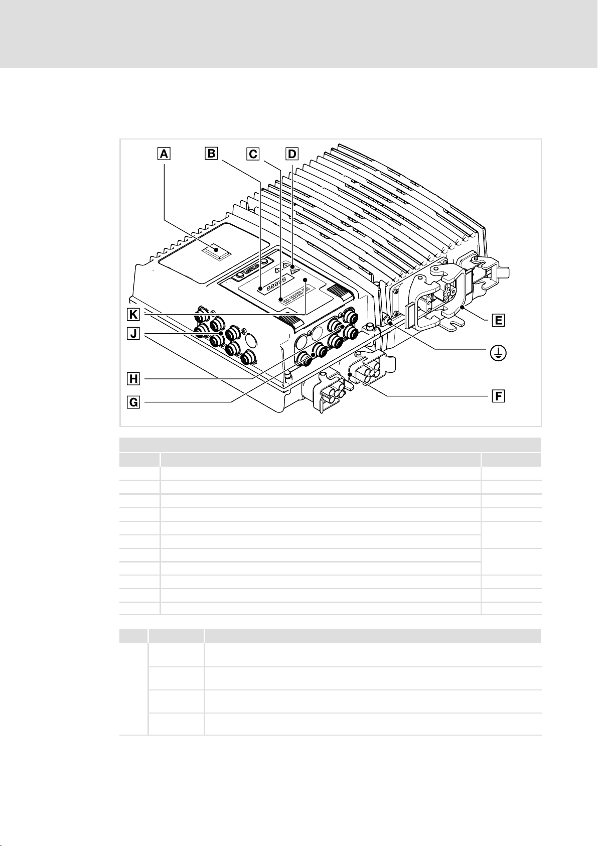
EMS version
E84DWGA015 b
Control elements and connection overview of the EMS version
Pos. Description/function Page(s)
Control element, various versions, optional 23
Display for values and messages, 5 characters 165
LED status display 159
Warning symbols See below
Motor and brake resistor connections
Mains connections and EMS−specific communication
Fieldbus connections
Input and output connections
EMS extension connection 22
Infrared receiver/transmitter 165
PE connections, M6 thread −
Pos. Icon Description
Long discharge time: All power terminals remain live for up to 3 minutes after mains
disconnection!
High discharge current: Carry out fixed installation and PE connection according to
EN 61800−5−1!
Electrostatic sensitive devices: Before working on the device, the personnel must be free
of electrostatic charge!
Hot surface: Risk of burns! Hot surfaces should not be touched without wearing
protective gloves.
From 87
From 64
26
EDS84DPS424 EN 5.0
Page 27

3.5 Communication
The available combinations of communication and connection system can be seen from
the table.
Type code characteristics Connection system version
Communication
(fieldbus)
CANopen
PROFIBUS
PROFINET / EtherNet/IP
1)
C
P
R / G
Product description
Communication
CAN port
Input /
output area
configuration
1 − − −
5 − − −
1 − − −
3 − −
5 − − −
7 − −
1)
1 − − −
2 − − −
3 − −
4 − −
5 − − −
6 − − −
7 − −
8 − −
Push−pull M12 M12 M12 M12
Fieldbus SSI
3)
Analog input CAN on board
3
2)
2)
2)
2)
2)
2)
3.5.1 CAN port
Detailed information on CAN can be found in the software manual.
CAN on board
"CAN on board" is only suited for short point−to−point connections between two
controllers, e.g. for synchronisation. Pay attention to notes on EMC−compliant wiring and
short cable lengths as there is no isolation towards the control electronics of the controller.
Node address and baud rate must be parameterised using the »Engineer«.
CANopen
CANopen is executed as isolated fieldbus and suited for multiple−node networks.
In case of fieldbuses, node address and baud rate can be set using the DIP switch under the
service hatch or parameterised using the »Engineer«.
designed
1)
cannot be combined with safety options 20 and 30
2)
cannot be combined with safety option 30
3)
not in StateLine version
− impossible
EDS84DPS424 EN 5.0
27
Page 28

3
Product description
Communication
Infrared remote control receiver
3.5.2 Infrared remote control receiver
For remote control, the devices are equipped with an infrared receiver (IrRC) (supported
from SW version 12 onwards).
The actions enabled by the infrared remote control (LDEZIRRC) are freely programmable.
For more information see the software manual and the online help for the LS_IRInterface
system block.
Note!
A trouble−free operation of the optical interface requires:
ƒ Clear line of sight between transmitter and receiver
– Maximum distance IrRC: ~ 5 m
– Maximum distance IrDA: ~ 1 m
– Angle of incidence: ~ 30 °
– Avoid direct solar radiation
– Environment without interfering transmitter (e.g. from adjacent stations)
ƒ Clean and scratch−free service hatch
3.5.3 Extensions in EMS version
For EMS device versions, additional interfaces are implemented for control :
ƒ Additional digital inputs and outputs
ƒ Infrared data interface (IrDA)
ƒ RS485 and/or RS422 serial interface
The type designation indicates which extensions are implemented in a device ( 23).
Overview of EMS extensions
Indicator in the
type code
B
C 1 x 1 x
D − 2 x
designed
− impossible
Digital I/O RS485 RS422 CANopen master PLC
X45, X46, X47, X48 X81, X82 X34
M12, 5−pole, A−coded M12, 8−pole, A−coded M12, 5−pole, A−coded
6 x DI
2 x DI/O
(X46 configurable)
Connection
2 x −
28
EDS84DPS424 EN 5.0
Page 29

3.5.4 Infrared interface
The EMS versions come with an implemented infrared interface for data transfer (IrDA).
The actions enabled via the interface or the reading of parameter data (codes) are freely
programmable in the PLC program.
Note!
A trouble−free operation of the optical interface requires:
ƒ Clear line of sight between transmitter and receiver
– Maximum distance IrRC: ~ 5 m
– Maximum distance IrDA: ~ 1 m
– Angle of incidence: ~ 30 °
– Avoid direct solar radiation
– Environment without interfering transmitter (e.g. from adjacent stations)
ƒ Clean and scratch−free service hatch
Product description
Communication
Infrared interface
3
EDS84DPS424 EN 5.0
29
Page 30

3
3.6 Concepts for the mains connection
Product description
Concepts for the mains connection
Concepts for the connection of individual axes
8400 protec controllers support the implementation of various concepts for the mains
connection. Here, a distinction is drawn between wiring using a:
ƒ Standard cable − commercially available cable
ƒ Hybrid cable − special cable for mains voltage and buffer/control voltage, including
shielding if required
The following must be observed when selecting the wiring:
ƒ Permissible back−up fuse: max. 32 A
ƒ Permissible current for plug contacts 24 V supply: max. 10 A
ƒ Select the cable cross−sections in compliance with applicable standards and
directives.
– Mains/PE: max. 6 mm
– 24 V supply: max. 2.5 mm
2
2
3.6.1 Concepts for the connection of individual axes
The following versions are possible according to device version (see type code for mains
connection system):
Standard cable
The mains voltage is connected to the controller by means of a standard cable (plug X10).
The 24 V supply of the controller is generated inside the device (mains−operated supply).
After the mains voltage has been switched off, all device functions including the control
electronics are deactivated. The switch function of Ethernet fieldbuses is also inactive.
Hybrid cable with external 24 V buffer voltage
The mains voltage and an external 24 V buffer voltage are fed using a hybrid cable (plug
X10). Depending on the state of the external 24 V supply, it is possible for the control
electronics to remain active even if the mains is switched off.
Standard cable with external 24 V buffer voltage
Since the connector housings only allow for one cable access per Q4/2 connector, the
E84DxM... device version (loop−through technique) can be used to implement this concept
for connection.
Here, the mains voltage is connected to the controller by means of a standard cable (plug
X10). The external 24 V buffer voltage is connected by means of a standard cable (plug
X11). Depending on the state of the external 24 V supply, it is possible for the control
electronics to remain active even if the mains is switched off.
30
Note!
This concept for connection implies that the mains voltage at plug X10 is also
applied at plug X11 at the same time.
EDS84DPS424 EN 5.0
Page 31

Wiring principle
Product description
Concepts for the mains connection
Concepts for the connection of individual axes
3
3/PE AC
E84Dx ...P
~~~
===
X10
4
8400 protec in version E84DxP...
X10 Mains connection 3/PE AC with standard cable
8400 protec in version E84DxP...
X10 Mains connection 3/PE AC with 24 V DC buffer voltage and hybrid cable
8400 protec in version E84DxM...
X10 Mains connection 3/PE AC with standard cable
X11 24 V DC buffer voltage with standard cable
3/PE AC
24 V DC
E84D ...xP
X10
6
3/PE AC
24 V DC
E84D ...xM
X10
X11
4
2
E84DVK001
EDS84DPS424 EN 5.0
31
Page 32

3
3.6.2 Concepts for the connection of the power bus
Product description
Concepts for the mains connection
Concepts for the connection of the power bus
Spacious plants are often organised in lines. A clearly structured cable routing leads to a
typical line topology. Two connection types are used:
ƒ Loop−through technique from device to device
– Here, the mains voltage and the 24 V buffer voltage are applied at X10 and X11 at
the same time.
ƒ Branch of power distributors
Depending on the type of cables and the 24 V supply, the following implementations are
possible.
Possible loop−through arrangements:
Standard cable
The mains voltage is distributed among the devices by means of a standard cable (plugs
X10 and X11). The 24 V supply of the controller is generated inside the device
(mains−operated supply). After the mains voltage has been switched off, all device
functions including the control electronics are deactivated. The switch function of
Ethernet fieldbuses is also inactive.
Hybrid cable with external 24 V buffer voltage
The mains voltage and an external 24 V buffer voltage (self−contained) are distributed
among the devices using a cable (plugs X10 and X11). Depending on the state of the
external 24 V supply, it is possible for the control electronics to remain active even if the
mains is switched off.
Arrangements including power distributors:
Standard cable including power distributors
The mains voltage is carried in a cable and distributed to the device by power distributors
(plug X10). The 24 V supply of the controller is generated inside the device (mains−operated
supply). After the mains voltage has been switched off, all device functions including the
control electronics are deactivated. The switch function of Ethernet fieldbuses is also
inactive.
Hybrid cable with power distributors and external 24 V buffer voltage
The mains voltage and the 24 V buffer voltage are carried in a cable and distributed to the
device by power distributors (plug X10). Depending on the state of the external 24 V
supply, it is possible for the control electronics to remain active even if the mains is
switched off.
32
EDS84DPS424 EN 5.0
Page 33

Product description
Concepts for the mains connection
Concepts for the connection of the power bus
Standard cable with power distributors and external 24 V buffer voltage
Isolated cable routing for mains voltage and 24 V buffer voltage.
Here, the mains voltage is connected to the controller by means of a standard cable (plug
X10). The external 24 V buffer voltage (self−contained) is connected by means of a standard
cable (plug X11). Depending on the state of the external 24 V supply, it is possible for the
control electronics to remain active even if the mains is switched off.
3
EDS84DPS424 EN 5.0
33
Page 34

3
Product description
Concepts for the mains connection
Concepts for the connection of the power bus
Wiring principle
~
=
X10 X10
X11 X11
3/PE AC
4
~
=
X10 X10
X11 X11
3/PE AC
24 V DC
6
E84D ...xP E84D ...xPE84D ...xM E84D ...xM
~
=
~
=
~
=
X10 X10
3/PE AC
4
E84D ...xP E84D ...xPE84D ...xM E84D ...xM
~
=
~
=
X10 X10
3/PE AC
24 V DC
6
~
=
E84D ...xM E84D ...xM
~
=
X10 X10
X11 X11
3/PE AC
24 V DC
Loop−through technique with 8400 protec in version E84DxM...
X10, X11 Mains connection 3/PE AC with standard cable
Loop−through technique with 8400 protec in version E84DxM...
X10, X11 Mains connection 3/PE AC with 24 V DC supply voltage and hybrid cable
Power distributor with 8400 protec in version E84DxP...
X10 Mains connection 3/PE AC with standard cable
Power distributor with 8400 protec in version E84DxP...
X10 Mains connection 3/PE AC with 24 V DC supply voltage and hybrid cable
Power distributor with 8400 protec in version E84DxM...
X10 Mains connection 3/PE AC with standard cable
X11 24 V DC buffer voltage with standard cable
4
2
~
=
E84DVK002
34
EDS84DPS424 EN 5.0
Page 35

3.7 EMS mains connection concepts
The mains connection concepts can also be realised with 8400 protec EMS, e.g.
ƒ Loop−through technique from device to device for multi−axis applications
Moreover, 8400 protec EMS controllers support the following (depending on the device
version):
ƒ Contact conductor connection for mains, control bar and message bar (half wave
and coded half wave)
ƒ Control signals via mains voltage (power wave)
ƒ Control signals via rail bus
ƒ Inductive transmission of energy and signals
For establishing a drive system, more adjusted components are required.
3.7.1 Half wave (coded)
Product description
EMS mains connection concepts
Half wave (coded)
3
L1
L2
L3
PE
SS
MS
E84D .../EP E84D .../EM
E84D ...LP E84D ...LM
~
=
X10
66
3/PE AC
SS/MS SS/MS
L1 ... L3, PE Sliding bar conductors for mains and PE conductor
SS Control bar SS1, SS2
ms Message bar MS1
8400 protec EMS controller for single−axis drive
8400 protec EMS controller for multi−axis drive
X10 Mains
X11 Mains loop−through technique
CAN CANopen communication
Controller, e.g. 8400 motec, as auxiliary drive
X1 Mains (with accessory plug−in module E84DZEVB...: X10)
3/PE AC 3/PE AC
~
=
CAN
X10 X1
X11
4
E84D ...G
~
=
E84DVK004_A
EDS84DPS424 EN 5.0
35
Page 36

3
Product description
EMS mains connection concepts
Power wave
3.7.2 Power wave
L1
L2
L3
PE
SS
3/PE AC
SS SS
E84D ...PP
~
=
E84D ...PM E84D ...G
~
=
CAN
X10
L1 ... L3, PE Sliding bar conductors for mains and PE conductor
SS Control bar Data±, SS1
8400 protec EMS controller for single−axis drive
8400 protec EMS controller for multi−axis drive
X10 Mains
X11 Mains loop−through technique
CAN Communication of CANopen master PLC
Controller, e.g. 8400 motec, as auxiliary drive
X1 Mains (with accessory plug−in module E84DZEVB...: X10)
X10 X1
X11
55
3/PE AC 3/PE AC
4
~
=
E84DVK004_B
36
EDS84DPS424 EN 5.0
Page 37

Product description
EMS mains connection concepts
DECA bus
3
3.7.3 DECA bus
L1
L2
L3
PE
Data
Data
E84D ...DP
~
=
E84D ...DM E84D ...G
~
=
CAN
X10
3/PE AC
2 Data 2 Data
L1 ... L3, PE Sliding bar conductors for mains and PE conductor
Data Signal rails Data±, SS1
8400 protec EMS controller for single−axis drive
8400 protec EMS controller for multi−axis drive
X10 Mains
X11 Mains loop−through technique
CAN Communication of CANopen master PLC
Controller, e.g. 8400 motec, as auxiliary drive
X1 Mains (with accessory plug−in module E84DZEVB...: X10)
X10 X1
X11
66
3/PE AC 3/PE AC
4
~
=
E84DVK004_C
EDS84DPS424 EN 5.0
37
Page 38

3
Product description
EMS mains connection concepts
Inductive
3.7.4 Inductive
Power1
Power2
Data
Data
Data Data
E84D ...FP
~
=
X10
44
560 V DC 560 V DC 560 V DC
24 V DC 24 V DC
Power1/2 Inductive energy transmission
(24 V DC for controlling a motor holding brake)
Data Inductive data transfer
8400 protec EMS controller for single−axis drive
8400 protec EMS controller for multi−axis drive
X10 Mains
X11 Mains loop−through technique
CAN Communication of CANopen master PLC
Controller, e.g. 8400 protec, as auxiliary drive
X10 DC mains voltage
E84D ...FM
~
=
CAN
X10 X10
X11
2
E84D ...xP
~
=
E84DVK004_D
38
EDS84DPS424 EN 5.0
Page 39

General data and operating conditions
4 Technical data
4.1 General data and operating conditions
General data
Conformity and approval
Conformity
CE
Approval
CULUS
2006/95/EC Low−Voltage Directive 13.1
UL 508C
CSA 22.2 No. 14
− No UL approval for control element W
Technical data
Power Conversion Equipment, File No. 132659
4
EDS84DPS424 EN 5.0
39
Page 40

4
Technical data
General data and operating conditions
Protection of persons and equipment
Enclosure EN 60529
NEMA Type 4X, indoor only
(Earth) leakage current EN 61800−5−1 > 3.5 mA AC, > 10 mA DC Observe the regulations and
Total fault current < 100 mA
additional equipotential
bonding
Protective insulation of
control circuits
Insulation resistance EN 61800−5−1
Short−circuit strength EN 61800−5−1
Protective measures for Short circuit on the motor side at switchon and during
Cyclic mains switching 3 switching/minute
Installation EN 60204−1 Cable protection on the supply side is max. 32 A with
EN 61800−5−1 Safe isolation from mains by double (reinforced) insulation
IP65
Deviating enclosure by
options:
IP64 with control element
C
IP54 with control element
W
IP55 with external fan for
7.5 kW devices
Earth−leakage circuit breakers of type B can be used.
M6 thread outside at the housing for connecting a 16mm@ PE
cable
< 2000 m site altitude: Overvoltage category III
> 2000 m site altitude: Overvoltage category II
Motor connection:
Limited, controller is inhibited, error acknowledgement
required
Phase/phase not
earth−fault−proof
Motor holding brake
connection: no
Brake resistor connection:
no
PTC connection: not
earth−fault−proof
Control terminals: full
operation
Earth fault at switchon
Motor stalling
Motor overtemperature
– Input for PTC or thermal contact
2
t monitoring
–I
maximally 20 switching/hour
A circuit that can be reset automatically protects the device
against destruction.
cable cross−section (L1, L2, L3): 6 mm
laying system B2
max. short−circuit current: < 10 kA
All unused connectors must be
closed with protection covers or
blanking plugs.
safety instructions!
Max. short−circuit current to be
expected: 10 kA
2
40
EDS84DPS424 EN 5.0
Page 41

General data and operating conditions
Operating conditions
Ambient conditions
Climatic
Storage
Transport EN 60721−3−2 2K3 (−25 ... +75 °C)
Operation EN 60721−3−3
Site altitude 0 ... 4000 m amsl
Pollution EN 61800−5−1 Degree of pollution 2
Mechanical
Vibration resistance (9.81 m/s
Transport
Operation
EN 60721−3−1
2
= 1 g)
EN 60721−3−2 2M2
EN 61800−2
Germanischer Lloyd General conditions: Acceleration resistant up to 2 g
EN 60721−3−3 3M4
EN 61800−5−1
1K3 (−25 ... +60 °C) < 6 months
1K3 (−25 ... +60 °C) > 6 months
3K3 (−25 ... +55 °C)
"K" or "L" safety system included: −25 ... +45 °C
Operation at 2/4 kHz: > +45 °C: Reduce the rated output
current by 2.5 %/°C.
Operation at 8/16 kHz: > +40 °C: Reduce the rated output
current by 2.5 %/°C.
Above 1000 ... 4000 m amsl: Reduce the rated output current
by 5 %/ 1000 m.
2 ... 9 Hz: Amplitude 3.5 mm
10 ... 200 Hz: Acceleration resistant up to 10 m/s
200 ... 500 Hz: Acceleration resistant up to 15 m/s
10 ... 57 Hz: Amplitude 0.075 mm
57 ... 150 Hz: Acceleration resistant up to 1 g
Technical data
> 2 years: Anodise DC bus
capacitors
4
2
2
Supply conditions
Mains connection
Power system
TT, TN
(with earthed
neutral)
IT Only permitted with devices of voltage class "E" (see type
Motor connection
Motors EN 60034 Only use motors suitable for inverter operation. Insulation
Length of the motor
cable
Operation is permitted without any restrictions.
code).
resistance:
min. û 1.5 kV, min. du/dt 5 kV/s
< 20 m (Lenze system cable, shielded)
EDS84DPS424 EN 5.0
41
Page 42

4
Technical data
General data and operating conditions
Mounting conditions
Mounting place Wall
Ensure convection cooling in the niches.)
Mounting position
Standard mounting
Free space 72
Requirements on the motor cable
Capacitance per unit length
2
1.5 mm
2.5 mm2/AWG 12 C
Electric strength
/AWG 16 C
VDE 0250−1 U0/U
UL U 600 V
Display to the front
Vertically suspended, −30 ... +30 °
In case of greater angles of tilt:
Operation at 2/4 kHz: > +40 °C: Reduce the rated output
current by 2.5 %/°C.
Operation at 8/16 kHz: > +35 °C: Reduce the rated output
current by 2.5 %/°C.
Core/core/CCore/shield
core/core/CCore/shield
0.6/1.0 kV
=
75/150 pF/m
100/ 150 pF/m
(U0 = r.m.s. value external − conductor/PE,
U = r.m.s. value − external conductor/external
conductor)
(U = r.m.s. value external conductor/external
conductor)
42
EDS84DPS424 EN 5.0
Page 43

Technical data
General data and operating conditions
EMC
Noise emission
Cable−guided
Radiation Category C2
Noise immunity (according to requirements of EN 61800−3)
Electrostatic discharge
(ESD)
Radio frequency
Cable−guided EN 61000−4−6 150 kHz ... 80 MHz, 10 V/m 80 % AM (1kHz)
Interference (housing) EN 61000−4−3 80 MHz ... 1000 MHz, 10 V/m 80 % AM (1kHz)
Burst
Power terminals and
interfaces
Signal interfaces EN 61000−4−4 1 kV/5 kHz
Control terminals EN 61000−4−4 2 kV/5 kHz
Surge
Power terminals EN 61000−4−5 1.2/50 s,
Control terminals EN 61000−4−5 1.2/50 s, 1 kV
Operation on public supply
systems
EN 61800−3
EN 61000−4−2 8 kV with air discharge,
EN 61000−4−4 2 kV/5 kHz
EN 61000−3−2
EN 61000−3−12
EN 61000−3−2
EN 61000−3−12 Mains current > 16 A: further measures are required for
Up to 20 m shielded motor cable (Lenze system cable):
category C2
4 kV with contact discharge against housing
1 kV phase/phase, 2 kV phase/PE
The devices are intended for use in an industrial
environment. When being used on public network,
additional measures must be taken to limit the expected
radio interference. The compliance with the requirements for
the machine/plant is the responsibility of the manufacturer
of the machine or system!
< 0.5 kW: with mains choke
0.5 ... 1 kW: with active filter
> 1 kW at mains current 16 A: No limit values for harmonic
currents
compliance with the standard
4
EDS84DPS424 EN 5.0
43
Page 44

4
Technical data
General data and operating conditions
Open and closed loop control
Open and closed loop control processes
VFCplus:
V loop (linear or square−law)
V/f closed loop
SLVC:
Sensorless vector control (torque/speed)
Only for HighLine
device version
from SW version 12 VFCplus eco:
Switching frequency
Torque behaviour
Setting range 1 : 10 In a setting range of 3 ... 50 Hz
Sensorless vector control (speed)
Minimum output
frequency
Setting range 1 : 10 Based on 50 Hz and M
Accuracy 0.5 %
Smooth running 0.1 Hz
Output frequency
Range −1000 Hz ... +1000 Hz
Absolute resolution 0.2 Hz
Standardised
resolution
Digital setpoint selection
Accuracy 0.01 %
Analog setpoint selection
Accuracy % Based on the final value
SC:
Servo control (torque/speed)
Energy−efficient V/f characteristic
SL PSM:
Sensorless synchronous control (torque/speed)
2 kHz, 4 kHz, 8 kHz, 16 kHz,
Optionally noise optimised or power−loss optimised
0.5 Hz (0 ... M
Parameter data: 0.01 %, process data: 0.006 % (= 214)
rated
)
rated
In a setting range of 3 ... 50 Hz
44
EDS84DPS424 EN 5.0
Page 45

Technical data
General data and operating conditions
EMS version
Half−wave system
E84DE..., E84DL...
Control bar
Z system No
Number 2
Signal level
Reference voltage or switched
voltage
Rated voltage
Switching threshold 50 Hz: 270 V AC (243 ... 297 V AC)
Power input 1.5 W (400 V AC) for 1 x half wave
Signalling bar
Number 1
Signal level
Reference voltage or switched
voltage
Short circuit protection PTC protection (500 connected in series)
Reference voltage 400 ... 480 V
Switching current max. 28 mA AC
Full wave
Positive half wave
Negative half wave
Coded half wave
L3
L1 possible with different hardware configuration
400−480 V AC, 50−60 Hz
Coded half wave: 230 V AC, 50−60 Hz
60 Hz: 330 V AC (297 ... 363 V AC)
Full wave
Positive half wave
Negative half wave
L3
L1 possible with different hardware configuration
4
EDS84DPS424 EN 5.0
45
Page 46

4
Technical data
Rated data
Overview
4.2 Rated data
4.2.1 Overview
Basis of the data
Mains Voltage Voltage range Frequency range
3/PE AC 400 320 − 0 % ... 440 + 0 % 45 − 0 % ... 65 + 0 %
3/PE AC 500 400 − 0 % ... 550 + 0 % 45 − 0 % ... 65 + 0 %
Output switching frequency f = 4 kHz
Input data
U
[V] U
Lrated
[V] f [Hz]
Lrated
Voltage Frequency Rated current [A]
[V] [Hz] up to +45 °C up to +55 °C
E84Dxxxx7514 400/500 50/60 4.1/3.2 3.0/2.4 3
E84Dxxxx1524 400/500 50/60 5.5/4.4 3.5/3.1 3
E84Dxxxx3024 400/500 50/60 9.7/7.9 7.3/6.0 3
E84Dxxxx4024 400/500 50/60 12.9/11.0 9.5/8.1 3
E84DHxxx7524 400/500 50/60 20.8/16.6 15.6/12.5 3
Ambient temperature during operation
Number of
phases
Rated data of the 24−V buffer voltage (preserves the control functionality in the event of
a mains failure):
Supply voltage for control electronics of the controller
(safely separated power supply unit SELV/PELV)
Typ Voltage range UDC [V DC] Current consumption at + 24 V DC [A]
E84Dxxxx7514
E84Dxxxx1524
E84Dxxxx3024
E84Dxxxx4024
E84DHxxx7524
1)
according to optional equipment, digital inputs and outputs are not wired
2)
digital inputs and outputs are completely wired
(+19.2 − 0 % ... +28.8 + 0 %)
+ 24
1)
Min.
0.2 ... 0.6 2
Max.
2)
46
Note!
The maximum total current of the 24 V voltage supply for external actuators
and encoders is 1 A, e.g. ports
ƒ Digital inputs/outputs at X4x,
ƒ Analog input at X50 or SSI at X80, and
ƒ Serial interfaces RS485/RS422 at X81/X82.
EDS84DPS424 EN 5.0
Page 47

Output data
Technical data
Rated data
Overview
4
Voltage Frequency Rated current [A]
[V] [Hz] up to +45 °C up to +55 °C
E84Dxxxx7514 0 ... 400/500 0 ... 1000 2.4/1.9 1.8/1.4 3
E84Dxxxx1524 0 ... 400/500 0 ... 1000 3.9/3.1 2.9/2.3 3
E84Dxxxx3024 0 ... 400/500 0 ... 1000 7.3/5.8 5.5/4.4 3
E84Dxxxx4024 0 ... 400/500 0 ... 1000 9.5/7.6 7.1/5.7 3
E84DHxxx7524 0 ... 400/500 0 ... 1000 16.0/12.8 12.0/9.6 3
Ambient temperature during operation
Number of
phases
Power losses
Power loss PV [W]
Type when operating with rated output current I
E84Dxxxx7514 66
E84Dxxxx1524 84
E84Dxxxx3024 127
E84Dxxxx4024 155
E84DHxxx7524 232
arated
when controller is inhibited
27
EDS84DPS424 EN 5.0
47
Page 48

4
Technical data
Rated data
Operation at rated mains voltage 400 V
4.2.2 Operation at rated mains voltage 400 V
Basis of the data
Mains Voltage Voltage range Frequency range
U
[V] U
Lrated
3/PE AC 400 320 − 0 % ... 440 + 0 % 45 − 0 % ... 65 + 0 %
Mains current Output power Motor power
at I
arated
Type I
E84Dxxxx7514 4.1 1.5 0.75
E84Dxxxx1524 5.5 2.4 1.5
E84Dxxxx3024 9.7 4.6 3.0
E84Dxxxx4024 12.9 5.9 4.0
E84DHxxx7524 20.8 10.0 7.5
2 kHz 4 kHz 8 kHz 16 kHz
Type I
arated2
E84Dxxxx7514 2.4 4.8 2.4 4.8 2.4 4.8 1.6 4.0
E84Dxxxx1524 3.9 7.8 3.9 7.8 3.9 7.8 2.3 6.4
E84Dxxxx3024 7.3 14.6 7.3 14.6 7.3 14.6 4.9 9.5
E84Dxxxx4024 9.5 19.0 9.5 19.0 9.5 17.0 6.3 9.5
E84DHxxx7524 16.0 32.0 16.0 32.0 16.0 30.0 10.7 21.3
[A] S
Lrated
Output currents [A] at switching frequency
I
aM2
I
arated4
[V] f [Hz]
Lrated
U, V, W 4 pol. ASM
[kVA] P
arated
I
aM4
I
arated8
I
aM8
I
arated16
arated
[kW]
I
aM16
I
aNx
I
aMx
Switching
frequency
Rated value of continuous output current
Maximum output current (overload current)
Periodic load change of 3 s with I
the tables under chapter 4.4
Can be obtained in the setting "x kHz fixed/..." in C00018
and recovery time of 12 s according to
aMx
If the maximum heatsink temperature is reached, the switching frequency is
reduced to 4 kHz.
In the setting "x kHz var./..." in C00018 the switching frequency is reduced
depending on the output current.
Depending on the switching frequency and e.g. the ambient temperature, it
may be required to reduce the output current (chapter 4.1, operating
conditions).
48
EDS84DPS424 EN 5.0
Page 49

Operation at rated mains voltage 400 V
Rated data for internal brake chopper
Technical data
Rated data
4
Switching threshold V
R
Bmin
Type
[]
: 725 V, adjustable
BRmax
I
BRmax
[A]
P
BRmax
[kW]
I
[A]
BRd
P
Bd
[kW]
t
[s]
Z
t
on
[s]
Internal brake resistor
E84Dxxx7514
E84Dxxx1524
220 3.3 2.4 0.5 0.05
1)
− − −
E84Dxxx3024
E84Dxxx4024
− − − − − − − −
E84Dxxx7524
External brake resistor
E84Dxxx7514 150 4.8 3.5 1.4 0.9 300 60 −
E84Dxxx1524 150 4.8 3.5 2.9 2.0 300 60 −
E84Dxxx3024 47 15.4 11.2 5.7 3.9 300 60 −
E84Dxxx4024 47 15.4 11.2 7.5 5.2 300 60 −
E84Dxxx7524 47 15.4 11.2 14.1 9.8 300 60 −
R
Bmin
I
BRmax
P
BRmax
I
BRd
P
Bd
t
Z
t
on
− t
t
Z
t
fp
1)
on
Minimum brake resistance, nominal value ±10 %
Peak current
Peak braking power
Continuous current RMS − important for the dimensioning of the cables
Continuous braking power
Cycle time, periodic load change with running time and recovery time
Running time
Recovery time
Maximum running time without initial load and compliance with the recovery
time
Max. heat QB: 3 kWs
Max. power loss in the internal brake resistor P
: see table
Bdav
t
fp
[s]
E84Dxxx7514
E84Dxxx1524
f
I
a
P
T
ch
Bdav
amb
f
ch
I
a
[kHz] [A] T
4
8
4
8
2.4 50 47 − 27
1.4 50 41 − 21
2.4 48 34 21 −
1.4 36 23 10 −
3.9 42 28 − 8
2.34 50 47 − 27
3.9 22 9 0 −
2.34 48 34 21 −
Output switching frequency
Motor current
Permissible power loss in the internal brake resistor, averaged over 60 s and
dependent on T
amb
(Linear interpolation/extrapolation via T
application must limit the power loss in the brake resistor to P
Ambient temperature
P
[W]
Bdav
20 °C 30 °C 40 °C 45 °C
amb
is permissible. Here, the
amb
Bdav
PBd.)
EDS84DPS424 EN 5.0
49
Page 50

4
Technical data
Rated data
Operation at rated mains voltage 400 V
Fuses and cable cross−sections
Operation without external mains choke/mains filter
Type Installation according to EN 60204−1
L1, L2, L3 − Laying system L1, L2, L3
B2 C F
[A] [A] [mm2] [mm2] [mm2] [A] [AWG] [mA]
E84Dxxxx7514 32 32 6 − − 30 8 300
E84Dxxxx1524 32 32 6 − − 30 8 300
E84Dxxxx3024 32 32 6 − − 30 8 300
E84Dxxxx4024 32 32 6 − − 30 8 300
E84DHxxx7524 32 32 6 − − 30 8 300
1)
These values are recommendations only. Other dimensioning values/laying systems are possible (e.g. according to
VDE 0298−4). The cable cross−sections apply under the following conditions: Use of PVC−insulated copper cables,
conductor temperature < 70 °C, ambient temperature < 45°C, no bundling of cables or cores, three loaded cores.
2)
Use UL−approved cables, fuses and fuse holders only.
UL fuse: voltage 500 V, tripping characteristic for example "H", "K5" or "CC". The cable cross−sections apply under
the following conditions: conductor temperature < 75 °C, ambient temperature < 45°C.
3)
Universal−current sensitive earth−leakage circuit breaker, short−time delay
If cables are longer than 50 m, the protective circuit−breaker may respond, depending on the cable type and
switching frequency.
Circuit breaker
Fuse of gG/gL utilisation category or semiconductor fuses of gRL utilisation category
Fuse
Observe national and regional regulations
1)
Installation according
to UL
2)
3)
FI
50
EDS84DPS424 EN 5.0
Page 51

Technical data
Rated data
Operation at a rated mains voltage of 500 V
4
4.2.3 Operation at a rated mains voltage of 500 V
Basis of the data
Mains Voltage Voltage range Frequency range
U
[V] U
Lrated
3/PE AC 500 400 − 0 % ... 550 + 0 % 45 − 0 % ... 65 + 0 %
Mains current Output power Motor power
at I
arated
Type I
E84Dxxxx7514 3.2 1.5 0.75
E84Dxxxx1524 4.4 2.4 1.5
E84Dxxxx3024 7.9 4.6 3.0
E84Dxxxx4024 11.0 5.9 4.0
E84DHxxx7524 16.6 10.0 7.5
2 kHz 4 kHz 8 kHz 16 kHz
Type I
arated2
E84Dxxx7514 1.9 4.8 1.9 4.4 1.9 4.4 1.3 3.1
E84Dxxx1524 3.1 7.8 3.1 7.2 3.1 7.2 1.7 3.4
E84Dxxx3024 5.8 14.6 5.8 13.5 5.8 13.5 3.9 7.4
E84Dxxx4024 7.6 19.0 7.6 17.6 7.6 13.4 5.1 7.3
E84DHxx7524 12.8 25.6 12.8 25.6 12.8 24.0 8.5 17.1
[A] S
Lrated
Output currents [A] at switching frequency
I
aM2
I
arated4
[V] f [Hz]
Lrated
U, V, W 4 pol. ASM
[kVA] P
arated
I
aM4
I
arated8
I
aM8
I
arated16
arated
[kW]
I
aM16
I
aNx
I
aMx
Switching
frequency
Rated value of continuous output current
Maximum output current (overload current)
Periodic load change of 3 s with I
the tables under chapter 4.4
Can be obtained in the setting "x kHz fixed/..." in C00018
and recovery time of 12 s according to
aMx
If the maximum heatsink temperature is reached, the switching frequency is
reduced to 4 kHz.
In the setting "x kHz var./..." in C00018 the switching frequency is reduced
depending on the output current.
Depending on the switching frequency and e.g. the ambient temperature, it
may be required to reduce the output current (chapter 4.1, operating
conditions).
EDS84DPS424 EN 5.0
51
Page 52

4
Technical data
Rated data
Operation at a rated mains voltage of 500 V
Rated data for internal brake chopper
Switching threshold V
R
Bmin
Type
[]
: 790 V, adjustable
BRmax
I
BRmax
[A]
P
BRmax
[kW]
I
[A]
BRd
P
Bd
[kW]
t
[s]
Z
t
on
[s]
Internal brake resistor
E84Dxxx7514
E84Dxxx1524
220 3.6 2.8 0.5 0.05
1)
− − −
E84Dxxx3024
E84Dxxx4024
− − − − − − − −
E84Dxxx7524
External brake resistor
E84Dxxx7514 150 5.3 4.2 1.4 1.2 300 60 −
E84Dxxx1524 150 5.3 4.2 2.9 2.5 300 60 −
E84Dxxx3024 47 16.8 13.3 5.7 4.9 300 60 −
E84Dxxx4024 47 16.8 13.3 14.1 12.2 300 60 −
R
Bmin
I
BRmax
P
BRmax
I
BRd
P
Bd
t
Z
t
on
− t
t
Z
t
fp
1)
on
Minimum brake resistance, nominal value ±10 %
Peak current
Peak braking power
Continuous current RMS − important for the dimensioning of the cables
Continuous braking power
Cycle time, periodic load change with running time and recovery time
Running time
Recovery time
Maximum running time without initial load and compliance with the recovery
time
Max. heat QB: 3 kWs
Max. power loss in the internal brake resistor P
: see table
Bdav
t
fp
[s]
E84Dxxx7514
E84Dxxx1524
f
I
a
P
T
ch
Bdav
amb
f
ch
I
a
[kHz] [A] T
4
8
4
8
1.9 50 47 − 27
1.14 50 41 − 21
1.9 48 34 21 −
1.14 36 23 10 −
3.1 42 28 − 8
1.86 50 47 − 27
3.1 22 9 0 −
1.86 48 34 21 −
Output switching frequency
Motor current
Permissible power loss in the internal brake resistor, averaged over 60 s and
dependent on T
amb
(Linear interpolation/extrapolation via T
application must limit the power loss in the brake resistor to P
Ambient temperature
P
[W]
Bdav
20 °C 30 °C 40 °C 45 °C
amb
is permissible. Here, the
amb
Bdav
PBd.)
52
EDS84DPS424 EN 5.0
Page 53

Technical data
Rated data
Operation at a rated mains voltage of 500 V
Fuses and cable cross−sections
Operation without external mains choke/mains filter
Type Installation according to EN 60204−1
L1, L2, L3 − Laying system L1, L2, L3
B2 C F
[A] [A] [mm2] [mm2] [mm2] [A] [AWG] [mA]
E84Dxxxx7514 32 32 6 − − 30 8 300
E84Dxxxx1524 32 32 6 − − 30 8 300
E84Dxxxx3024 32 32 6 − − 30 8 300
E84Dxxxx4024 32 32 6 − − 30 8 300
E84DHxxx7524 32 32 6 − − 30 8 300
1)
These values are recommendations only. Other dimensioning values/laying systems are possible (e.g. according to
VDE 0298−4). The cable cross−sections apply under the following conditions: Use of PVC−insulated copper cables,
conductor temperature < 70 °C, ambient temperature < 45°C, no bundling of cables or cores, three loaded cores.
2)
Use UL−approved cables, fuses and fuse holders only.
UL fuse: voltage 500 V, tripping characteristic for example "H", "K5" or "CC". The cable cross−sections apply under
the following conditions: conductor temperature < 75 °C, ambient temperature < 45°C.
3)
Universal−current sensitive earth−leakage circuit breaker, short−time delay
If cables are longer than 50 m, the protective circuit−breaker may respond, depending on the cable type and
switching frequency.
Circuit breaker
Fuse of gG/gL utilisation category or semiconductor fuses of gRL utilisation category
Fuse
Observe national and regional regulations
1)
Installation according
to UL
2)
FI
4
3)
EDS84DPS424 EN 5.0
53
Page 54

4
Technical data
Current characteristics
4.3 Current characteristics
The controller limits its maximally possible motor current under the following operating
conditions ("current derating"):
ƒ If the maximum heatsink temperature is exceeded
– In this case, the controller switches independently from switching frequency mode
of 16 kHz to 8 kHz and from 8 kHz to 4 kHz (but not from 4 kHz to 2 kHz). This
function can be deactivated via C00144.
When the heatsink temperature continues to rise, the inverter output will be
inhibited and the error message "Trip" occurs. This also occurs when the switching
frequency reduction is deactivated.
ƒ In case of output frequencies f
out
< |5 Hz|
ƒ As a function of the switching frequency modes "fixed" or "variable"
01
I
OUT
I
aM
I
aM02
I
aM04
I
aM08
I
aM016
0055
f [Hz]
out
I
aM2
I
aM4
I
aM8
I
aM16
Fig. 4−1 Current derating characteristics
Derating curve depending on the fixed switching frequency
Derating curve depending on the variable switching frequency
I
out
I
aM
I
aMx
I
aM0x
I
aMv
I
aM0v
f
out
Output current
Maximum output current (overload current)
Maximum output current (overload current) at different switching frequencies: 2kHz,
4kHz, 8kHz and 16kHz
Maximum output current (overload current) at f
frequencies: 2kHz, 4kHz, 8kHz, 16kHz
Maximum output current (overload current) at a variable switching frequency
Maximum output current (overload current) at f
frequency
Field frequency at the output U, V, W
I
OUT
I
aM
I
aM0v
I
aMv
f [Hz]
out
= 0Hz and different switching
out
= 0Hz and a variable switching
out
8400GG084
54
EDS84DPS424 EN 5.0
Page 55

Technical data
Current characteristics
Maximum output currents [A]1) at a fixed switching frequency and ULN = 400V
2 kHz 4 kHz 8 kHz 16 kHz
Type I
E84Dxxxx7514 4.8 4.8 4.8 4.8 2.8 4.8 1.8 4.0
E84Dxxxx1524 5.9 7.8 5.9 7.8 4.1 7.8 2.5 6.4
E84Dxxxx3024 11.0 14.6 11.0 14.6 9.5 14.6 5.5 9.5
E84Dxxxx4024 14.3 19.0 13.8 19.0 9.5 17.1 5.7 9.5
E84DHxxx7524 16.0 32.0 16.0 32.0 17.0 30.0 10.7 21.3
Type I
E84Dxxxx7514 4.8 4.8 4.4 4.4 2.1 4.4 1.4 3.1
E84Dxxxx1524 5.9 7.8 5.9 7.2 3.2 7.2 1.9 3.4
E84Dxxxx3024 11.0 14.6 10.6 13.5 7.4 13.5 4.2 7.4
E84Dxxxx4024 14.3 19.0 10.7 17.6 7.3 13.4 4.3 7.3
E84DHxxx7524 16.0 25.6 12.8 25.6 13.6 24.0 8.5 17.1
1)
The shown values apply to the operation with ambient temperatures of up to +45°C for 2/4kHz and up to +40°C for
8/16kHz. For ambient temperatures between +40/45°C and +55°C, a derating from 2.5 %/K to the given values must
be observed.
aM02
I
aM2
I
aM04
I
aM4
I
aM08
I
aM8
I
aM016
Maximum output currents [A]1) at a fixed switching frequency and ULN = 500V
2 kHz 4 kHz 8 kHz 16 kHz
aM02
I
aM2
I
aM04
I
aM4
I
aM08
I
aM8
I
aM016
I
aM16
I
aM16
4
EDS84DPS424 EN 5.0
55
Page 56

4
Technical data
Overcurrent operation
4.4 Overcurrent operation
The controllers are designed for an overcurrent limited in time. The load due to defined,
cyclic operation is determined by the "Ixt" monitoring function. The "Ixt" function
comprises two moving averaging procedures which are checked in parallel:
ƒ temporary moving averaging of the apparent motor current for pulse loads
ƒ continuous moving averaging of the apparent motor current for permanent loads
Type of utilisation Utilisation cycle
Pulse utilisation 15 s I
Permanent utilisation 180 s The monitoring function is
If the maximum value in code C00064/1 exceeds 100%, a "warning" will be generated or
a "trip" will be triggered (according to setting).
Monitoring function
Condition Code
> 160 % Display in C00064/2
aNx
permanently active.
Display of the maximum
value in C00064/1
Display in C00064/3
Display of the maximum
value in C00064/1
56
EDS84DPS424 EN 5.0
Page 57

Technical data
Overcurrent operation
The curves of typical load functions and the simulation of the "Ixt" function are shown in
the following illustration:
I [%]
aN8
0
2
100
4
1
0
Dt
1
Fig. 4−2 Overcurrent capacity at 45° C
Pulse load (15 s cycle) Calculation equation:
Peak current
Unloading current
Dt
1
Dt
2
Permanent load (180 s cycle) Calculation equation:
Peak current
Unloading current
Dt
3
Dt
4
I
arx
Dt
2
Peak current period
Unloading current period
Peak current period
Unloading current period
Rated value of continuous output
current
Dt
3
t
3
Dt
4
A @ Dt1)B @ Dt
Dt1)Dt
2
C @ Dt3)D @ Dt
Dt3)Dt
4
2
x 100%
4
x 100%
8400IZ180
EDS84DPS424 EN 5.0
57
Page 58

4
Technical data
Overcurrent operation
Type
E84Dxxx7514
E84Dxxx1524
E84Dxxx3024
E84Dxxx4024
E84Dxxx7524
I
amax/IaR8
f = 2 kHz f = 4 kHz f = 8 kHz f = 16 kHz
200
75 200 75 200 75
[%] in 15−s cycle
133 50
120 45
133 50
Type
E84Dxxx7514
E84Dxxx1524
E84Dxxx3024
E84Dxxx4024
E84Dxxx7524
Tip!
For calculations of application−specific cycles please contact your Lenze contact
person.
I
amax/IaR8
f = 2 kHz f = 4 kHz f = 8 kHz f = 16 kHz
150 75 150 75 150 75
[%] in 180−s cycle
100 50
90 45
100 50
58
EDS84DPS424 EN 5.0
Page 59

4.5 Terminal description
Overview
StateLine, HighLine
Technical data
Terminal description
4
Operational controls and connections
Pos. Function Description
Control element Optional
PE connection for M6 ring cable lug
X10 Mains and 24−V buffer voltage DESINA Q4/2, pins
Optional: Molex ( 87)
X11 Optional: Loop−through technique − mains and 24−V
buffer voltage
X20 Optional: For external brake resistor Q5/0, sockets (optional)
X21 Motor, temperature monitoring and motor holding
brake
X31 Fieldbus input Socket RJ45 or M12, A−coded, male
X32 Fieldbus output Socket RJ45 or M12, A−coded, female
X35 CAN on board M12, 5−pole sockets, A−coded
X41 Digital inputs DI1 and DI2
X42 Digital inputs DI3 and DI4, also configurable as digital
outputs DO1 and DO2
X43 Digital inputs DI5 and DI6
X50 Analog input AI, AU M12, 5−pole sockets, A−coded
X61 Safety system, option 10 M12, 5−pole pins, A−coded
X62
X63
Safety system, option 30
X64
X70 Diagnostics Socket RJ69
X80 Synchronous serial interface (SSI) M12, 8−pole sockets, A−coded
only E84DHxxx7524: External fan
Operating voltage for the external fan −
DESINA Q4/2, sockets (optional)
Optional: Molex
Optional: Molex
Q8/0, Modular or 10E, sockets
M12, 5−pole sockets, A−coded
M12, 5−pole sockets, A−coded
M12, 8−pole sockets, A−coded
E84DWGA010
EDS84DPS424 EN 5.0
59
Page 60

4
Technical data
Terminal description
EMS version
Operational controls and connections
Pos. Function Description
Control element Optional
PE connection for M6 ring cable lug
X10 Mains and 24−V buffer voltage DESINA Q4/2, pins
X11 Optional: Loop−through technique − mains and 24−V
buffer voltage
X20 Optional: For external brake resistor Q5/0, sockets (optional)
X21 Motor, temperature monitoring and motor holding
brake
X31 Fieldbus input M12, A−coded, pins
X32 Fieldbus output M12, A−coded, sockets
X34 CANopen master PLC M12, 5−pole, A−coded, sockets
X41 Digital inputs DI1 and DI2
X42 Digital inputs DI3 and DI4, also configurable as digital
outputs DO1 and DO2
X43 Digital inputs DI5 and DI6
Digital inputs DI7 and DI8
X45
Digital inputs DI9 and DI10, also configurable as digital
X46
outputs DO3 and DO4
Digital inputs DI11 and DI12
X47
Digital inputs DI13 and DI14
X48
X50 Analog input AI, AU M12, 5−pole sockets, A−coded
X70 Diagnostics Socket RJ69
X80 Synchronous serial interface (SSI) M12, 8−pole sockets, A−coded
X81
RS485/RS422 M12, 8−pole, A−coded, sockets
X82
DESINA Q4/2, sockets (optional)
Optional: Molex
Optional: Molex
Q8/0, Modular or 10E, sockets
M12, 5−pole sockets, A−coded
M12, 5−pole, A−coded, sockets
E84DWGA015 a
60
EDS84DPS424 EN 5.0
Page 61

4.6 Supply concept of control voltage
8400 protec controllers generate the 24 V supply voltage of the control electronics from
the mains voltage by means of an integrated power supply unit (mains−operated supply).
An external 24 V buffer voltage from a safely separated power supply unit (SELV/PELV)
must be connected in order to implement a self−contained supply of the control
electronics.
The 24 V supply voltage is required for the control electronics and other components such
as fieldbus communication and/or drive−based safety.
In addition, the supply voltage is available at the terminals, irrespective of the fact whether
it is fed internally or externally. Information on the supply voltage at the digital and analog
terminals is provided under:
ƒ Digital inputs( 64)
ƒ Digital outputs( 65)
ƒ Analog inputs( 66)
Technical data
Supply concept of control voltage
Internal 24 V supply voltage
4
ƒ Synchronous serial interface (SSI) ( 66)
The supply voltage is preferentially used for:
ƒ Connecting potential−free contacts to digital inputs
ƒ Supplying external sensors
At an external 24 V supply voltage, the rated values may deviate according to the voltage
source.
4.6.1 Internal 24 V supply voltage
At an internal 24 V supply voltage, the maximally permissible total current of terminals
X4x, X50/X8x is 1 A.
EDS84DPS424 EN 5.0
61
Page 62

4
Technical data
Supply concept of control voltage
External supply voltage 24 V
4.6.2 External supply voltage 24 V
Detailed information on the X10 and X11 pin assignment with the external 24 V supply is
provided on page 87.
Example circuit
int
E84D...
U24
+
=
-
1A
X4x 24O
X62 24_ACK
X10 24E
+
X10 GND
-
X11 24E
X11 GND
E84DVK003
X10 ... External 24 V buffer voltage at the mains connection
X11 ... External 24 V supply at the mains connection in loop−through technique
(for devices of the E84DxM... version)
X4x ... 24 V supply of the digital sensors
X62 ... 24 V supply of the safety system
U24 Internal 24 V supply
int Voltage supply of the control electronics
An external 24 V supply voltage must comply with the following rated values to ensure
trouble−free operation of the controller.
X10
Pin / Name Feature Rated value
11 / 24E
12 / GND
Connection for external 24 V supply
voltage by a safely separated power
supply unit (required for feeding the
control electronics and the
communication module independent
of the mains supply)
Suppression of voltage pulses Suppressor diode 36 V, bidirectional
Electric strength of external voltage +30 V
Excess current release Automatically resettable
Polarity reversal protection When polarity is reversed: No function and no
Current consumption
Capacity to be charged 2000 F
Max. load for plug contacts 10 A
24 V in accordance with IEC 61131−2
19.2 ... 28.8 V
Max. residual ripple 5 %
SELV/PELV
destruction
Approx. 0.6 A during operation if inputs/outputs are not
configured
Max. 2.0 A during operation with typical input/output
configuration
Max. 1.5 A starting current for 100 ms
62
EDS84DPS424 EN 5.0
Page 63

Supply concept of control voltage
External supply voltage 24 V
X11
Pin / Name Feature Rated value
11 / 24E
12 / GND
X4x, X50/X8x
Pin / Name Feature Rated value
1 / 24O
3 / GIO
Connection for an external 24 V
supply voltage (loop−through
arrangement)
Number of devices included in the
loop−through arrangement
Max. load for plug contacts 10 A
24 V supply of the external sensors or
potential−free contacts
Max. output current 200 mA per output
Total current for X4x, X50/X8x 1 A
Electric strength of external voltage +30 V
Excess current release Automatically resettable
24 V according to IEC 61131−2 (cp. X10)
is limited by the voltage drop due to max. current= 10 A
and max. cable cross−section = 2.5 mm
External supply at 24E: voltage drop < 2.5 V
Internal supply: DC 18 ... 28 V
Technical data
4
2
EDS84DPS424 EN 5.0
63
Page 64

4
Technical data
Control terminals
Digital inputs
4.7 Control terminals
4.7.1 Digital inputs
X41 ... X43
Pin / Name Features Rated value
4 / DI1
2 / DI2
4 / DI3
2 / DI4
4 / DI5
2 / DI6
1 / 24O
3 / GIO
Digital input 1/2 at X41 according to IEC 61131−2, type 1
Digital input 3/4 at X42 according to IEC 61131−2, type 1
Digital input 5/6 at X43 according to IEC 61131−2, type 1
24 V supply of the external sensors or
potential−free contacts
Total current for X4x, X50/X8x 1 A
or
two−track frequency input for HTL encoder
0 ... 100 kHz
DI4 − typical delay time:
5 s at rising edge
25 s at falling edge
or
Single−channel frequency input, 0 ... 10 kHz
DI5/DI6 − typical delay time:
5 s at rising edge
25 s at falling edge
External supply at 24E: Voltage drop < 2.5 V
Extensions in the EMS version
X45 ... X48
Pin / Name Features Rated value
4 / DI7
2 / DI8
4 / DI9
2 / DI10
4 / DI11
2 / DI12
4 / DI13
2 / DI14
5 / n. c. not assigned −
1 / 24O
3 / GIO
Digital input 7/8 at X45
Digital input 9/10 at X46
(configurable with DO3/DO4)
Digital input 11/12 at X47
Digital input 13/14 at X48
24 V supply of the external sensors or
potential−free contacts
Total current for X41 ... X48 1 A
according to IEC 61131−2, type 1
External supply at 24E: Voltage drop < 2.5 V
64
EDS84DPS424 EN 5.0
Page 65

4.7.2 Digital outputs
X42 − configured
Labelling Features Rated value
4 / DO1
2 / DO2
3 / GIO
Technical data
Control terminals
Digital outputs
Digital output
External−voltage protected up to +30 V
Isolation 76
Level LOW < +5 V
Time−dependent behaviour LOW − HIGH / HIGH − LOW
Behaviour during overload Reduced voltage or periodic switch−off/on
According to IEC61131−2, type 1
Integrated polarity reversal protection diode for
switching inductive loads
High > +15 V
max. 250 s
4
1 / 24O
3 / GIO
Behaviour in case of reset and during
switch−on
Cycle time 1 ms
Max. output current 200 mA per output
24 V supply of the external sensors or
potential−free contacts
Total current for X4x, X50/X8x 1 A
Outputs are switched−off (LOW)
External supply at 24E: Voltage drop < 2.5 V
Extensions in the EMS version
X46 − configured
Labelling Features Rated value
4 / DO3
2 / DO4
3 / GIO
1 / 24O
3 / GIO
Digital output
External−voltage protected up to +30 V
Isolation 76
Level LOW < +5 V
Time−dependent behaviour LOW − HIGH / HIGH − LOW
Behaviour during overload Reduced voltage or periodic switch−off/on
Behaviour in case of reset and during
switch−on
Cycle time 1 ms
Max. output current 200 mA per output
24 V supply of the external sensors or
potential−free contacts
Total current for X4x, X50/X8x 1 A
According to IEC61131−2, type 1
Integrated polarity reversal protection diode for
switching inductive loads
High > +15 V
max. 250 s
Outputs are switched−off (LOW)
External supply at 24E: Voltage drop < 2.5 V
EDS84DPS424 EN 5.0
65
Page 66

4
Technical data
Control terminals
Analog inputs
4.7.3 Analog inputs
X50
Pin / Name Feature Rated value
4 / AU
3 / GA
2 / AI
3 / GA
1 / 24O
3 / GIO
Voltage input
Input resistance > 80 k
Sampling frequency 1 kHz (1 ms)
Accuracy 0.1 V
Electric strength of external voltage 15 V
A/D converter Resolution 10 bits + sign
Current input, parameterisable
Input resistance 220
Input current in case of open circuit Display "0" (I < 0.6 mA)
Sampling frequency 1 kHz (1 ms)
Accuracy 0.2 mA
Electric strength of external voltage 15 V
A/D converter 10 bit resolution
24 V supply of the external sensors or
potential−free contacts
Total current for X4x, X50/X8x 1 A
0.3 ... 10 V
(V < 0.3 V
Error: 1 digit 0.1 %, based on the final value
0.6 ... +20 mA (I < 0.6mA ¢ "0")
4 ... +20 mA, fail−safe
Error: 1 digit 0.1 %, based on the final value
External supply at 24E: Voltage drop < 2.5 V
¢ "0")
4.7.4 Synchronous serial interface (SSI)
X80
Pin / Name Feature Rated value
1 / CLK+ Pos. clock signal
2 / CLK− Neg. clock signal
3 / Data+ Pos. data line
4 / Data− Neg. data line
5 / n. c. Not assigned
6 / n. c. Not assigned
8 / 24O
7 / GIO
24 V supply of the external SSI encoders External supply at 24E: Voltage drop < 2.5 V
Total current for X4x, X50/X8x 1 A
4.7.5 Remote control (IrRC)
IrRC (Infrared Remote Control)
Pin / Name Features Rated value
−
Reach ~5 m
Angle of incidence ~30 °
Bit rate: 100 .... 1000 kbits
Data word width: 1 ... 32 bits (effective)
Code: Gray an binary
66
EDS84DPS424 EN 5.0
Page 67

4.7.6 Interfaces of the EMS version
CANopen Master PLC
X34
Pin / Name Features Rated value
1 / Shielding (functional earth) −
2 / n. c. not assigned −
3 / CAN_GND CAN GND
4 / CANH CAN HIGH
5 / CANL CAN LOW
RS485/422 PLC
X81/X82
Pin / Name Features Rated value
RS485 RS422
The
assignment
depends on the
device version
( 133).
RS485A’ Reception + (Data+)
RS485B’ Reception (Data−)
RS485A Transmission+ (CLK+)
RS485B Transmission− (CLK−)
24 V supply according to IEC 61131−2, type 1
Technical data
Control terminals
Interfaces of the EMS version
Bit rate: adjustable up to 1 Mbit
Isolation: Function separation
according to:
– ANSI/TIA/EIA−485−A−98
– ANSI/TIA/EIA−422
Bit rate: Adjustable up to 115.2 kbit
Isolation: Function separation
At RS422, PLC supports evaluation of SSI
encoders (max. 150 kHz).
4
Infrared interface (IrDA)
IrDA (Infrared Data Association)
Pin / Name Features Rated value
−
Reach ~1 m
Angle of incidence ~30 °
EDS84DPS424 EN 5.0
67
Page 68

4
Technical data
Control terminals
Motor holding brake connection
4.7.7 Motor holding brake connection
Version according to type code: B (AC voltage: fast switch)
X21
Pin / Name Feature Rated value
Connection of a motor holding brake to the external brake rectifier in the motor terminal box
Max. switching capacity 55 W
Internal switching time < 10 ms
Isolation Basic insulation ( 76)
Time−dependent behaviour See software manual, chapter holding brake
Behaviour in case of reset and during
switch−on
Operating frequency Max. 60/min
Short−circuit strength no
c2 / ~
c3 / ~
c4 / S1
c5 / S2
Switched mains voltage (L1/L2) for a brake rectifier
Switching voltage AC 400/480 V according to IEC 61131−2
Potential−free contact for switching the brake rectifier on the DC side
Switching voltage DC 250 V
Version according to type code: F (DC voltage: integrated brake rectifier)
control / parameterisation
Outputs are switched−off / open
X21
Pin / Name Feature Rated value
6 / BD1
4 / BD2
Connection of a motor holding brake
Integrated brake rectifier Half−wave rectification with increased ripple
Output voltage
(dependent on mains voltage)
Max. output power 55 W
Internal switching time < 1 ms
Time−dependent behaviour See software manual, chapter holding brake
Short−circuit strength no
Behaviour in case of reset and during
switch−on
Operating frequency Max. 60/min
AC 400 V DC 180 V
AC 500 V DC 225 V
control / parameterisation
Outputs are switched off
Version according to type code: V (24 V DC Voltage)
X21
Pin / Name Feature Rated value
6 / BD1
4 / BD2
Connection of a motor holding brake
Output voltage
(dependent on input voltage)
Max. output power 48 W
Internal switching time < 1 ms
Time−dependent behaviour See software manual, chapter holding brake
Short−circuit strength Yes
Behaviour in case of reset and during
switch−on
Operating frequency Max. 60/min
DC 24 V
control / parameterisation
Outputs are switched off
68
EDS84DPS424 EN 5.0
Page 69

Technical data
Control terminals
Motor holding brake connection
Version according to type code: C (DC voltage: cold brake)
X21
Pin / Name Feature Rated value
6 / BD1
4 / BD2
Connection of a motor holding brake
Voltage boost for 0.3 s 130 %
Voltage reduction (cold brake) after 0.3 s 65 %
Half−wave rectification with increased ripple
Output voltage
(dependent on mains voltage)
Max. output power 55 W
Internal switching time < 1 ms
Time−dependent behaviour See software manual, chapter holding brake
Short−circuit strength no
Behaviour in case of reset and during
switch−on
Operating frequency Max. 60/min
AC 400 V DC 180 V
AC 500 V DC 225 V
control / parameterisation
Outputs are switched off
4
Stop!
Damage of the devices
A defective motor holding brake or a short circuit on the X21 connection
(motor and built−on accessories) causes internal damage to the device.
Possible consequences:
ƒ If a defective motor holding brake is connected, the replacement device is
also damaged immediately.
Protective measures:
ƒ When devices are replaced due to malfunction of the brake control, ensure
that defect−free motor holding brakes are connected.
ƒ Check whether the motor holding brake and the connecting cable are free
from defects.
ƒ Replace or repair defective components.
EDS84DPS424 EN 5.0
69
Page 70

5
Mechanical installation
Important notes
5 Mechanical installation
5.1 Important notes
ƒ If the cooling air is polluted (fluff, (conductive) dust, soot, aggressive gases), take
adequate countermeasures, as e.g.:
– Cleaning of the cooling ribs on the controller in regular intervals
– Separate air guide
ƒ Possible mounting position:
– Vertically suspended
ƒ Maintain the specified free spaces above and below the controller to other
installations!
ƒ Ensure untroubled cooling and exhaust air flow.
ƒ In case of continuous vibrations or shocks use vibration dampers.
Depending on the size, four or six screws M6 x >10 mm are required for the mounting. The
mounting location and material must ensure a durable mechanical connection.
For fastening the devices, we recommend:
ƒ M6 cheese head screw, hexagon socket, according to DIN 912/ISO 4762
ƒ M6 cheese head screw, torx, according to ISO 14579
70
EDS84DPS424 EN 5.0
Page 71

Mechanical installation
Dimensions
5
5.2 Dimensions
[mm]
E84DWGA021
[mm]
a c c1 = c2 c3 c4 e1 [kg]
E84Dxxxx7514
E84Dxxxx1524
E84Dxxxx3024
E84Dxxxx4024
E84DHxxx7524 434 290 145 92 52 195 9.1 ... 9.6
353
434 290 145 92 52 148 8.9 ... 9.4
186 − 92 75 110 7.0 ... 7.5
EDS84DPS424 EN 5.0
71
Page 72

5
5.3 Mounting clearance
Mechanical installation
Mounting clearance
Note!
The actual free space is determined by the connectors used and the cable
bending radii.
[mm]
E84DWGA025
72
EDS84DPS424 EN 5.0
Page 73

Electrical installation − HighLine/StateLine version
Important notes
6 Electrical installation − HighLine/StateLine version
6.1 Important notes
Danger!
Dangerous electrical voltage
All power terminals remain live for up to three minutes after mains
disconnection.
Possible consequences:
ƒ Death or severe injuries when touching the power terminals.
Protective measures:
ƒ Switch off the power supply and wait for at least three minutes before
working on the power terminals.
ƒ Make sure that all power terminals are deenergised.
6
Danger!
ƒ The contacts of the power connectors X10, X11, X20 and X21 may carry
dangerous voltage if the frequency inverter is connected to the mains. Thus,
deenergise the frequency inverter before working on it.
ƒ Earth the device by means of X10 and by connecting it to functional earth
(earthing bolt) in order to prevent injury to persons and malfunctioning.
Danger!
Dangerous voltage
The leakage current to earth (PE) is > 3.5 mA AC or > 10 mA DC.
Possible consequences:
ƒ Death or severe injuries when the device is touched in the event of a fault.
Protective measures:
ƒ Implement the actions required in the EN 61800−5−1. Especially:
– Fixed installation
– PE connection must conform to standards (PE conductor diameter
10 mm
2
or PE conductor must be connected twice)
EDS84DPS424 EN 5.0
73
Page 74

6
Electrical installation − HighLine/StateLine version
Important notes
Stop!
No device protection if the mains voltage is too high
The mains input is not internally fused.
Possible consequences:
ƒ Destruction of the device if the mains voltage is too high.
Protective measures:
ƒ Observe the maximally permissible mains voltage.
ƒ Fuse the device correctly on the supply side against mains fluctuations and
voltage peaks.
Stop!
The device contains components that can be destroyed by electrostatic
discharge!
Before working on the device, the personnel must ensure that they are free of
electrostatic charge by using appropriate measures.
Stop!
Pluggable terminal strips or plug connections
Plugging or removing the terminal strips or plug connections during operation
may cause high voltages and arcing.
Possible consequences:
ƒ Damage of the devices
Protective measures:
ƒ Switch off device.
ƒ Only plug or remove the terminal strips or plug connections in deenergised
status.
Note!
Switching on the controller motor side is permissible for safety shutdown
(emergency stop) and for operation of several motors on the controller in V/f
operating mode.
Please observe the following:
ƒ When switching with the controller is enabled, you can activate monitoring
functions of the controller. If no monitoring function is activated, switching
is permissible.
ƒ The switching elements at the motor end must be rated for DC voltages
V
DCmax
= 800 V.
74
EDS84DPS424 EN 5.0
Page 75

Electrical installation − HighLine/StateLine version
Note!
Only with the control element
ƒ C = service switch with protective function
the device can be disconnected from the mains voltage.
Note!
The counter plugs of the power terminals must be equipped with connector
housings with a vertical outgoing cable.
Note!
ƒ It is absolutely necessary to keep the plastic caps on the connectors for the
control terminals and interfaces!
ƒ During transport, storage, and operation, ports not used must be sealed
using the plastic caps, in order to maintain the product features in
accordance with the technical data.
ƒ Only if this note is observed, the product features certified are ensured for
devices with a safety system.
6
Important notes
EMC−compliant wiring
Note!
ƒ Establish a good conductive connection to protective earth by means of a
copper−braid cable (e.g. mounting surface, machine earth or building earth).
ƒ Lay control cables and data lines separately from the motor cables.
ƒ Connect the shields of the control cables and data lines at both ends.
EDS84DPS424 EN 5.0
75
Page 76

6
Electrical installation − HighLine/StateLine version
Important notes
Electrical isolation
6.1.1 Electrical isolation
The protective insulation of the "8400 Inverter Drives" controllers is implemented
according to EN 61800−5−1. The following illustration shows the insulation concept.
Fig. 6−1 Electrical isolation between power terminals, control terminals and housing
X10
X11
X21
X20
X10
(24 V)
X11
(24 V)
X21
(T1/T2)
X20
(T1/T2)
Isolation by functional insulation
X22
X3x
X4x
X80X6x
X70
X50
E84DWPT005
Power connections
X10, X11 Mains
X21 Motor
X20 Brake resistor
Control terminals
X10 (24 V)
X11 (24 V)
X20 (T1/T2) brake resistor temperature monitoring
X21 (T1/T2) Motor temperature monitoring
X22 Voltage supply of external fan − only for 7.5 kW devices
X3x Fieldbus communication
X4x Digital inputs/outputs
X50 Analog input
X6x Safety system
X70 Diagnostics
X80 SSI
6.1.2 Device protection
ƒ In case of condensation, do not connect the controller to the mains voltage before
the moisture has evaporated completely.
I
II
Isolation by basic insulation
Safe isolation by double or reinforced insulation
Protection against accidental contact is guaranteed without any further
measures.
24 V supply voltage
76
ƒ The controller must be protected by external fuses.
ƒ Unused control inputs and outputs must be closed according to the intended type of
protection.
EDS84DPS424 EN 5.0
Page 77

Electrical installation − HighLine/StateLine version
6.1.3 Maximum motor cable length
ƒ Keep the motor cable as short as possible since this has a positive effect on the drive
behaviour.
ƒ The maximally permissible motor cable length is: 20 m, shielded
– at rated mains voltage
– at a switching frequency of 8 kHz
Note!
If the conditions for electromagnetic compatibility must be observed, the
permissible cable lengths may vary.
6.1.4 Motor protection
ƒ Extensive protection against overload:
– By overcurrent relays or temperature monitoring.
– We recommend the use of PTC thermistors or thermostats to monitor the motor
temperature.
– PTC thermistors or thermostats can be connected to the controller.
– For monitoring the motor, we recommend the use of the I
Important notes
Maximum motor cable length
2
xt monitoring.
6
ƒ Only use motors with an insulation suitable for the inverter operation:
– Insulation resistance: min. û = 1.5 kV, min. du/dt = 5 kV/s
– When using motors with an unknown insulation resistance, please contact your
motor supplier.
EDS84DPS424 EN 5.0
77
Page 78

6
Electrical installation − HighLine/StateLine version
Safety instructions for the installation according to UL or U
R
6.2 Safety instructions for the installation according to UL or U
Original − English
Warnings!
ƒ Branch circuit protection:
Suitable for use on a circuit capable of delivering not more than 200 000 rms
symmetrical amperes, 500 V maximum.
– When Protected by CC, T, or J Class Fuses.
ƒ Integral solid state protection does not provide branch circuit protection.
Branch circuit protection must be provided in accordance with the National
Electrical Code and any additional local codes.
ƒ Overload Protection = 125 % of rated FLA.
ƒ Use 75 °C copper wire only, except for control circuits.
ƒ Use Class 1 wire only.
ƒ Enclosed Device, suitable for use in a UL Type 4X (Indoor) Environment.
ƒ Suitable for use in a surrounding air temperature of 45 °C, and
– additionally 55 °C when de−rating rules are followed.
ƒ Suitable for use in a compartment handling conditioned air.
ƒ The device is provided with internal overload protection. For information on
the protection level of the internal overload protection for a motor load, see
the corresponding Software Manual or Online Help under the topic "Motor
load monitoring (I
must be changed from "Warning" (factory setting) to "Fault".
ƒ For information on rating and proper connection of the thermal protector
(only for connection to motors having integral thermal protection), see the
corresponding Manual or Online Help.
2
xt)". This function has to be activated; i. e. the reaction
R
78
Warnings!
The opening of branch−circuit protective device may be an indication that a
fault has been interrupted.
To reduce the risk of fire or electric shock, current−carrying parts and other
components of the controller should be examined and replaced if damaged or
equivalent.
EDS84DPS424 EN 5.0
Page 79

Electrical installation − HighLine/StateLine version
Safety instructions for the installation according to UL or U
6
R
6.3 Safety instructions for the installation according to UL or U
Original − French
Avertissement !
ƒ Protection par disjoncteur :
Convient aux circuits non susceptibles de délivrer plus de 200 000 ampères
symétriques eff., maximum 500 V.
– Protection par des fusibles CC de calibre T ou J.
ƒ La protection statique intégrée n’offre pas la même protection qu’un
disjoncteur. Une protection par disjoncteur externe doit être fournie,
conformément au National Electrical Code et aux autres dispositions
applicables au niveau local.
ƒ Protection contre les surcharges = 125 % de l’intensité assignée à pleine
charge.
ƒ Utiliser exclusivement des conducteurs en cuivre 75 °C, sauf pour la partie
commande.
ƒ Utiliser impérativement un câble de classe 1.
ƒ Equipement monté dans un coffret de protection adapté à une utilisation en
environnement UL de type 4X (intérieur).
ƒ Convient à une utilisation à une température ambiante maximale de 45 °C
ainsi que
– 55 °C en cas d’application des règles de réduction de puissance.
ƒ Convient pour une utilisation dans un a espace à air conditionné.
ƒ L’équipement est doté d’un dispositif de protection intégré contre les
surcharges. Pour obtenir des informations sur le niveau de protection offert
par la protection intégrée contre les surcharges du moteur, se reporter au
manuel du logiciel ou à l’aide en ligne correspondante, rubrique
"Surveillance de la charge du moteur (I
En d’autres termes, la réaction doit être modifiée de "Avertissement"
(réglage usine) à "Défaut".
ƒ Pour obtenir des informations sur les caractéristiques assignées et sur le
raccordement correct du dispositif de protection thermique (uniquement
pour raccordement à des moteurs dotés d’une protection thermique
intégrée), se reporter au manuel correspondant ou à l’aide en ligne.
2
xt)". Cette fonction doit être activée.
R
EDS84DPS424 EN 5.0
Avertissement !
Le déclenchement du dispositif de protection du circuit de dérivation peut être
dû à une coupure qui résulte d’un courant de défaut.
Pour limiter le risque d’incendie ou de choc électrique, examiner les pièces
porteuses de courant et les autres éléments du contrôleur et les remplacer s’ils
sont endommagés.
79
Page 80

6
Electrical installation − HighLine/StateLine version
Installation according to EMC (installation of a CE−typical drive system)
Shielding
6.4 Installation according to EMC (installation of a CE−typical drive system)
Design of the cables
ƒ It is imperative to comply with the regulations concerning minimum cross−sections
of PE conductors. The cross−section of the PE conductor must be at least as large as
the cross−section of the power connections.
ƒ The cables used must comply with the approvals required for the location (e.g. UL).
6.4.1 Shielding
Requirements
ƒ The effectiveness of a shielded cable is reached by:
– Providing a good shield connection through large−surface shield contact.
– Using only braided shields with low shield resistance made of tin−plated or
nickel−plated copper braid.
– Using braided shields with an overlap rate > 70 % and an overlap angle of 90 °.
– Keeping unshielded cable ends as short as possible.
Use system cables or shielded cables for these connections:
ƒ Motor
ƒ External brake resistor ( Mounting Instructions of the brake resistor)
ƒ Motor holding brake (shielding is required when being integrated into the motor
cable; connection to optional motor brake control)
ƒ Motor temperature monitoring
ƒ Analog signals (inputs and outputs; single−sided shield connection to the controller)
ƒ Fieldbus communication (e.g. CANopen ,PROFIBUS, PROFINET, ...)
ƒ Safety system
ƒ CAN on board
The following connections need not be shielded:
ƒ Mains
ƒ 24−V supply
ƒ Digital signals (inputs and outputs).
– We recommend to use shielded cables for a cable length from approximately 5 m
on or in environments with strong interferences.
Connection system
80
ƒ Directly apply the shielding in the plug.
– Extensively apply the shielding and ensure electrical conductivity.
– If required, additionally connect the shield to the cable clamp rail.
EDS84DPS424 EN 5.0
Page 81

Electrical installation − HighLine/StateLine version
Installation according to EMC (installation of a CE−typical drive system)
Motor cable
6
6.4.2 Motor cable
ƒ Only use shielded motor cables with braids made of tinned or nickel−plated copper.
Shields made of steel braids are not suitable.
– The overlap rate of the braid must be at least 70 % with an overlap angle of 90 °.
ƒ The cables used must correspond to the requirements at the location (e.g.
EN 60204−1).
ƒ Use Lenze system cables.
ƒ Extensively apply the shielding in the plug and attach it in a way which ensures
electrical conductivity.
ƒ The motor cable is optimally installed if
– it is separated from mains cables and control cables,
– it only crosses mains cables and control cables at right angles,
– it is not interrupted.
ƒ If the motor cable must be opened all the same (e.g. due to chokes, contactors, or
terminals):
– The unshielded cable ends may not be longer than 100 mm (depending on the
cable cross−section).
– Install chokes, contactors, terminals etc. spatially separated from other
components (with a min. distance of 100 mm).
– Install the shield of the motor cable directly before and behind the point of
separation to the mounting plate with a large surface.
ƒ Connect the shield with a large surface to PE in the terminal box of the motor at the
motor housing.
– Metal EMC cable glands at the motor terminal box ensure a large surface
connection of the shield with the motor housing.
EDS84DPS424 EN 5.0
81
Page 82

6
Electrical installation − HighLine/StateLine version
Installation according to EMC (installation of a CE−typical drive system)
Control cables
6.4.3 Control cables
ƒ Control cables must be shielded to minimise interference injections.
ƒ For lengths of 200 mm and more, use only shielded cables for analog and digital
inputs and outputs. Under 200 mm, unshielded but twisted cables may be used.
ƒ Connect the shield correctly:
– The shield connections of the control cables must be at a distance of at least 50
mm from the shield connections of the motor cables and DC cables.
– Connect the shield of digital input and output cables at both ends.
– Connect the shield of analog input and output cables at one end (at the drive
controller).
ƒ To achieve an optimum shielding effect (in case of very long cables, with high
interference) one shield end of analog input and output cables can be connected to
PE potential via a capacitor (e.g. 10 nF/250 V) (see sketch).
Fig. 6−2 Shielding of long, analog control cables
9300vec043
82
EDS84DPS424 EN 5.0
Page 83

Installation according to EMC (installation of a CE−typical drive system)
6.4.4 Wiring
Notes on the laying of cables:
ƒ In the case of greater cable lengths, a greater cable distance between the cables is
required.
ƒ In the case of parallel routing (cable trays) of cables with different types of signals,
the degree of interference can be minimised by using a metallic cable separator or
isolated cable ducts.
Electrical installation − HighLine/StateLine version
Cover
Barrier without
opening
6
Wiring
Signal cables
Fig. 6−3 Cable routing in the cable duct with barrier
Fig. 6−4 Cable routing in separated cable ducts
Cover
Cable duct
Power cables
Communication cables
Measuring cables
Analog cables
Control cables
Power cables
EMVallg001
EMVallg002
EDS84DPS424 EN 5.0
83
Page 84

6
Electrical installation − HighLine/StateLine version
Installation according to EMC (installation of a CE−typical drive system)
Wiring
Wiring on the mains side
ƒ It is possible to connect the controller, mains choke or RFI filter to the mains via
single cores or unshielded cables.
ƒ The cable cross−section must be rated for the assigned fuse protection (VDE 0160).
Wiring on the motor side
Stop!
The motor cable is highly susceptible to interference. Therefore you will
achieve an optimum wiring on the motor side if you
ƒ exclusively use shielded and low−capacitance motor cables.
ƒ do not integrate any further cable into the motor cable (e.g. for blowers
etc.).
ƒ shield the supply cable for temperature monitoring of the motor (PTC or
thermostat) and install it separately from the motor cable.
Special conditions allow you to integrate the supply cable for temperature monitoring of
the motor into the motor cable: ( 81)
Danger!
Uncontrolled motor movements can occur
If the motor cable is damaged, a short circuit between the brake control cables
and the motor cables can cause motor movements with low torque.
Possible consequences:
ƒ Personnel in the vicinity of the motor can be injured.
Protective measures:
ƒ Install motor cable in a protected way (e.g. in a cable duct).
84
EDS84DPS424 EN 5.0
Page 85

Electrical installation − HighLine/StateLine version
Installation according to EMC (installation of a CE−typical drive system)
Detecting and eliminating EMC interferences
6
6.4.5 Detecting and eliminating EMC interferences
Fault Cause Remedy
Interferences of analog
setpoints of your own or
other devices and
measuring systems
Unshielded motor cable Use shielded motor cable
Shield contact is not extensive enough Carry out optimal shielding as specified
Shield of the motor cable is interrupted
by terminal strips, switched, etc.
Install additional unshielded cables
inside the motor cable (e.g. for motor
temperature monitoring)
Too long and unshielded cable ends of
the motor cable
Separate components from other
component part with a minimum
distance of 100 mm
Use motor choke/motor filter
Install and shield additional cables
separately
Shorten unshielded cable ends to
maximally 40 mm
EDS84DPS424 EN 5.0
85
Page 86

6
Electrical installation − HighLine/StateLine version
Devices in a power range of 0.75 ... 7.5 kW (3/PE AC 400 V)
Example circuits
6.5 Devices in a power range of 0.75 ... 7.5 kW (3/PE AC 400 V)
6.5.1 Example circuits
X10
1
S1
3/PE AC 380 ... 500 V
+
3
4
112
X32
X31
12
X11
111234 12
X43
X42X41
=
U24
L1
L2
L3
PE
X61
X62
X63
X64
L1
L2
L3
PE
+
+24 V
+
GND
-
X50
+
E84D...
1325
X20
"
12
BRW1
+
"
+
T
h
X21
"
5
X21
-
+
T1 T2
BRK1
c
T1 T2
1
2
~~
+
GL1
BRK1
3
S1 S2
5
4
-
+
3
7
846
1
0
"
+
V
U
W
M
T
h
+
a
6
+
3~
3
2
1
1
"
+
V
U
W
M
T
h
+
3~
E84DWSP055
E84D... 8400 protec controller
S1 Service switch control element (optional)
U24 Supply voltage 24 V internal
BRK1 Spring−applied brake
GL1 Spring−applied brake control
BRW1 External brake resistor at optional terminal X20
− for E84DHxxx7524: Direct connection of the thermal contact
T
h
PTC thermistor (PTC) or thermal contact (NC contact)
M Motor
Motor connection system: Plug type Q8/0
Motor connection system: Plug type Modular
X31 ... X50 Communication, inputs and outputs
X61 ... X64 Optional: Drive−based safety
86
EDS84DPS424 EN 5.0
Page 87

Electrical installation − HighLine/StateLine version
Devices in a power range of 0.75 ... 7.5 kW (3/PE AC 400 V)
Terminal assignment of the power connections
6.5.2 Terminal assignment of the power connections
Mains connection
X10 − port for mains
Pin Connection Description Data
DESINA type Q4/2, pins
84DWTX0100
1 L1 Mains phase L1
2 L2 Mains phase L2
3 L3 Mains phase L3
PE PE conductor
11 24E External 24−V power supply
12 GND External reference potential
Max. 6 mm
Max. 2.5 mm
6
2
2
X10 − mains connection − device version E84DxH...
Pin Connection Description Data
1 4
2
1 L1 Mains phase L1
2 L2 Mains phase L2
3 L3 Mains phase L3
4 PE PE conductor
3
E84DWTXXMO 1
Type Molex, Brad Mini−Change, pins
max. 14 AWG
EDS84DPS424 EN 5.0
87
Page 88

6
Electrical installation − HighLine/StateLine version
Devices in a power range of 0.75 ... 7.5 kW (3/PE AC 400 V)
Terminal assignment of the power connections
X11 − mains loop−through technique (optional)
Pin Connection Description Data
DESINA type Q4/2, sockets
84DWTX0110
1 L1 Phase L1
2 L2 Phase L2
3 L3 Phase L3
PE PE conductor
11 24E External 24−V power supply
12 GND External reference potential
X11 − mains connection − device version E84DxH...
Pin Connection Description Data
1
5
Type Molex, Brad Mini−Change, pins
Max. 6 mm
Max. 2.5 mm
2
2
2
3
4 24E External 24 V voltage supply
2 GND External reference potential 24 V
3 PE PE conductor
1, 5 n. c. not assigned
4
E84DWTXXMO 2
max. 16 AWG
88
EDS84DPS424 EN 5.0
Page 89

Electrical installation − HighLine/StateLine version
Devices in a power range of 0.75 ... 7.5 kW (3/PE AC 400 V)
Terminal assignment of the power connections
Motor connection
X21 − motor connection − device version E84DxxC...
Pin Connection Description Data
12
4
67
+
3
8
5
84DWTX0210
2 n. c. Grooved pin as a protection against mix−up with power bus
1 U Motor phase U
3 W Motor phase W
7 V Motor phase V
4 BD2 Motor holding brake (reference
6 BD1 Motor holding brake
5 +PTC
8 −PTC
PE PE conductor Max. 4 mm
Type Q8/0, sockets
Use Lenze system cable:
EYP0037xxxxxxxxQ10, 8−core, 1.5 mm
EYP0038xxxxxxxxQ11, 8 core, 2.5 mm
2
2
Max. 4 mm
Max. output voltage: mains voltage
Max. permanent output current:
type−dependent
Max. 4 mm
conductor)
Motor temperature monitoring Max. 4 mm
PTC thermistor (PTC) or thermal
contact (NC contact)
2
2
2
2
6
X21 − motor connection − device version E84DxxB...
Pin Connection Description Data
Type Modular, sockets
Use Lenze system cable:
EYP0039xxxxxxxxQ08, 10−core, 1.5 mm
EYP0040xxxxxxxxQ09, 10−core, 2.5 mm
84DWTX0211
a1 U Motor phase U
a2 V Motor phase V
a3 W Motor phase W
c1 +PTC
Motor temperature monitoring Max. 4 mm
c6 −PTC
c2 ~
Supply voltage of brake rectifier Max. 4 mm
c3 ~
c4 S1
Switch for separation on the DC side
2
2
Max. 6 mm
Max. output voltage: mains voltage
Max. permanent output current:
type−dependent
PTC thermistor (PTC) or thermal
contact (NC contact)
V
= mains voltage−dependent
rated
The brake rectifier is mounted in the
terminal box of the motor.
c5 S2
PE PE conductor Max. 6 mm
2
2
2
2
EDS84DPS424 EN 5.0
89
Page 90

6
Electrical installation − HighLine/StateLine version
Devices in a power range of 0.75 ... 7.5 kW (3/PE AC 400 V)
Terminal assignment of the power connections
Stop!
Damage of the devices
A defective motor holding brake or a short circuit on the X21 connection
(motor and built−on accessories) causes internal damage to the device.
Possible consequences:
ƒ If a defective motor holding brake is connected, the replacement device is
also damaged immediately.
Protective measures:
ƒ When devices are replaced due to malfunction of the brake control, ensure
that defect−free motor holding brakes are connected.
ƒ Check whether the motor holding brake and the connecting cable are free
from defects.
ƒ Replace or repair defective components.
Note!
In the Lenze setting, the temperature monitoring of the motor is activated! To
start motors without thermal detectors, the response of the motor
temperature monitoring must be deactivated (C00585). Alternatively, a wire
jumper between +PTC and −PTC can be used to simulate a normal
temperature.
90
EDS84DPS424 EN 5.0
Page 91

Electrical installation − HighLine/StateLine version
Devices in a power range of 0.75 ... 7.5 kW (3/PE AC 400 V)
Terminal assignment of the power connections
Connection of external brake resistor
X20 − connection of external brake resistor (optional)
Pin Connection Description Data
Type Q5, sockets
E84DWX0202
1 RB2
2 RB1
3 T1
5 T2
4 n. c. not assigned
PE PE conductor
Brake resistor max. 2.5 mm
only E84DHxxx7524:
brake resistor temperature monitoring
6
2
X20 − connection of external brake resistor (optional, − device version E84DxH...)
Pin Connection Description Data
5
4
3
1 RB1
5 RB2
3 PE PE conductor
2, 4, 6 n. c. not assigned
1
2
6
E84DWTXXMO 3
Type Molex, Brad Mini−Change, sockets
Brake resistor max. 16 AWG
EDS84DPS424 EN 5.0
91
Page 92

6
Electrical installation − HighLine/StateLine version
Control terminals
Diagnostics
6.6 Control terminals
6.6.1 Diagnostics
The following can be optionally connected to the X70 diagnostic interface:
ƒ USB diagnostic adapter E94AZCUS
In combination with the Lenze PC software »Engineer«, the diagnostic adapter serves
to make comprehensive settings via dialogs, e.g. for initial commissioning.
ƒ EZAEBK2001diagnosis terminal
The diagnosis terminal comprises the keypad including housing and a connecting
cable.
The diagnosis terminal can be used to control or change individual settings. In a quick
commissioning menu, the basic settings of the controller can be parameterised using
the diagnosis terminal.
The X70 plug is located behind the service hatch. Apply a little pressure to open the service
hatch and push the two plastic bars down. Tools are not required.
After using the diagnostic interface, remove the connecting cable at X70 and completely
close the service hatch.
X70 − diagnostic interface
Pin Signal Description Data
Type RJ69, 10−pole, socket
8400HLC009
1 ... 10 internal Terminal for diagnosis terminal or diagnostic adapter
92
EDS84DPS424 EN 5.0
Page 93

Electrical installation − HighLine/StateLine version
Control terminals
Analog input
6
6.6.2 Analog input
The analog input can be used either as voltage input or as current input.
X50− analog inputs AI, AU
Pin Signal Description Data
1 24O 24 V supply of the external sensors
2 AI Current input 0 ... +20 mA
3 GA Reference potential
4 AU Voltage input 0 ... 10 V
5 Controller 10 V reference voltage (output) + 10 V, max. 10 mA
Type M12, 5−pole sockets
84DPSO05_5
4 ... +20 mA
EDS84DPS424 EN 5.0
93
Page 94

6
Electrical installation − HighLine/StateLine version
Control terminals
Analog input
Example circuit
GND-A
GND-A
E84D...
X50
24O
AU
GAAI
AR
"
8400DAI012 8400DAI013
GND-A
E84D...
X50
24O
AU
GAAI
AR
"
B
Fig. 6−5 Wiring examples of the analog input
Potentiometer with internal reference voltage AR
Potentiometer with external reference voltage
External master current selection based on a sensor signal 0 − 20 mA.
External master current selection based on a sensor signal 0 − 20 mA. External
sensor supply.
X50 Connection for analog input
GA GND−A Ground reference potential for the analog inputs and outputs
EMC shield connection
U Measuring device
B Measuring transducer
8400DAI009 8400DAI092
E84D...
E84D...
X50
X50
-
+
=
+
GND-A
AU
GAAI
AR
"
AU
GAAI
AR
24O
-
24O
"
=
B
94
EDS84DPS424 EN 5.0
Page 95

Electrical installation − HighLine/StateLine version
Control terminals
Digital inputs and outputs
6
6.6.3 Digital inputs and outputs
Note!
The maximum total current of the 24 V voltage supply for external actuators
and encoders is 1 A, e.g. ports
ƒ Digital inputs/outputs at X4x,
ƒ Analog input at X50 or SSI at X80, and
ƒ Serial interfaces RS485/RS422 at X81/X82.
Digital inputs
X41 − digital inputs DI1, DI2
Pin Signal Description Data
Type M12, 5−pole sockets
84DPSO05_5
1 24O 24 V supply of the external sensors
2 DI2 Digital input 2 According to IEC61131−2, type 1
3 GIO Reference potential HIGH
4
5 n. c. Not assigned
DI1 Digital input 1 8 mA at 24 V DC
or
Two−track frequency input for HTL
encoder 0 ... 100 kHz
+15 .... +30 V DC
LOW
0 ... +5 V
X42 − digital inputs DI3, DI4
Pin Signal Description Data
Type M12, 5−pole sockets
84DPSO05_5
1 24O 24 V supply of the external sensors
2 DI4
(DO2)
3 GIO Reference potential LOW 0 ... +5 V
4 DI3
(DO1)
5 n. c. Not assigned
Digital input 4
(also available as digital output)
Digital input 3
(also available as digital output)
HIGH +15 .... +30 V DC
8 mA at 24 V DC
EDS84DPS424 EN 5.0
95
Page 96

6
Electrical installation − HighLine/StateLine version
Control terminals
Digital inputs and outputs
X43 − digital inputs DI5, DI6
Pin Signal Description Data
Type M12, 5−pole sockets
84DPSO05_5
1 24O 24 V supply of the external sensors
2 DI6 Digital input 6 According to IEC61131−2, type 1
or
Single−channel frequency input, 0 ... 10
kHz
3 GIO Reference potential HIGH
LOW
4
DI5 Digital input 5 8 mA at 24 V DC
+15 .... +30 V DC
0 ... +5 V
5 n. c. Not assigned
Example circuit
GND-IO
GND-IO
3.3k
3.3k
GIO
X41
24O
S2
DI2
DI1
-
=
S1
+
8400DIO045 8400DIO022
Fig. 6−6 Wiring examples of the digital inputs
Wiring of digital inputs, examples:
S1 Potential−free contact, at internal 24 V supply
S2 Signal source, e.g. PLC or with external 24 V supply
Connection of an HTL incremental encoder with a maximum input frequency of
100 kHz
DI1 track A
DI2 track B
X41 Plugs for digital inputs X41 ... X43
GIO Ground reference potential for the digital inputs and outputs (GND−IO)
X41
24O
DI2
3.3k
3.3k
GIO
DI1
"
96
EDS84DPS424 EN 5.0
Page 97

Electrical installation − HighLine/StateLine version
Control terminals
Digital inputs and outputs
Digital outputs
Note!
If inductive loads are being connected, it is essential to use a spark suppressor
at the digital output.
X42 − digital outputs DO1, DO2 (configured digital input!)
Pin Signal Description Data
Type M12, 5−pole sockets
84DPSO05_5
1 24O 24 V supply of the external sensors
2 DO2 digital output 2 (configured) HIGH +24 V or VDC at X10
3
4 DO1 digital output 1 (configured) max. 200 mA per output
5 n. c. Not assigned
GIO Reference potential LOW 0 ... +5 V
6
Example circuit
GND-IO
GIO
24O DO2
X42
Fig. 6−7 Wiring examples of the digital inputs and outputs
DO1
8400DIO016
Digital control (relay, valve, ...) with internal 24 V supply
−
X42 Plug for the digital outputs (configured)
GIO Ground reference potential for the digital inputs and outputs (GND−IO)
EDS84DPS424 EN 5.0
97
Page 98

6
Electrical installation − HighLine/StateLine version
Control terminals
Synchronous serial interface (SSI)
6.6.4 Synchronous serial interface (SSI)
X80 − SSI
Pin Signal Description Data
M12 type, 8−pole sockets
84DPSO05_8
1 CLK+ Pos. clock signal
2 CLK− Neg. clock signal
3 Data+ Pos. data line
4 Data− Neg. data line
5 n. c. Not assigned −
6 n. c. Not assigned −
7 GIO Reference potential
8 24O 24 V supply of the external SSI encoders
External supply at 24E: Voltage drop < 2.5 V
Total current for X4x, X50/X8x: 1 A
98
EDS84DPS424 EN 5.0
Page 99

Electrical installation − HighLine/StateLine version
6.7 Communication
Carry out the installation in accordance with the mounting directives of the fieldbus
systems in order to prevent a faulty communication. Please observe the notes on the
additional equipotential bonding.
Stop!
High compensation currents
High compensation currents can flow via the shield of the fieldbus cable.
Possible consequences:
Damage to material assets or failures
Protective measures:
Prevent compensation currents via the shield of the fieldbus cable as follows:
ƒ Connect all fieldbus nodes with a 16 mm
ƒ Lay this cable in parallel to the bus cable.
ƒ Ensure a highly conductive connection of all earthing studs with a copper
braid cable to the mounting surface.
Communication
2
cable via the earthing studs.
6
EDS84DPS424 EN 5.0
E84DWX0003
Earthing for compliance with EMC conditions, prevents compensation currents via the
16 mm
shield of the fieldbus cable
2
equalizing conductor with ring cable lug M6
The communication cables of the available fieldbus systems can be installed using
different plug versions. The type code provides information on the design of one device.
99
Page 100

6
Electrical installation − HighLine/StateLine version
Communication
PROFINET® / EtherNet/IP
6.7.1 PROFINET® / EtherNet/IP
Push−pull plug
X31 − fieldbus input, X32 fieldbus output
Pin Signal Description Data
AIDA standard, type RJ45, socket, 8−pole
84DWTX0311
1 Tx+ Transmit path + (transmit)
2 Tx− Transmit path − (transmit)
3 Rx+ Receive path + (receive)
4 res.
5 res.
6 Rx− Receive path − (receive)
7 res.
8 res.
−
−
M12 plug, 4−pole
X3x − communication
Pin Signal Description Data
1 Tx+ Transmit path +
2 Rx+ Receive path +
3 Tx− Transmit path −
4 Rx− Receive path −
6.7.2 PROFIBUS®
X3x − communication
Pin Signal Description Data
1 P5V2 Only assigned at the output 5 V DC / 30 mA (bus termination)
2 RxD/TxD−N Data line A (received/transmitted data, minus)
3 M5V2 Data ground (ground to 5 V)
4 RxD/TxD−P Data line B (received/transmitted data, plus)
5 n. c. − (shield connection above the housing)
Type M12, 4−pole, D−coded
X31 −> sockets
X32 −> sockets
84DPSO05_5
Type M12, 5−pole, B−coded
X31 −> input −> pins
X32 −> output −> sockets
84DPSO05_5
100
The station address can be set via DIP switches 1 ... 64 behind the service hatch.
EDS84DPS424 EN 5.0
 Loading...