


 Loading...
IBM System x3250 M3 Types 4251, 4252, and 4261 |
|
Installation and User’s Guide
IBM System x3250 M3 Types 4251, 4252, and 4261 |
|
Installation and User’s Guide
Note: Before using this information and the product it supports, read the general information in Appendix B, “Notices,” on page 77 and the IBM Safety Information, IBM Environmental Notices and User's Guide on the IBM System x Documentation CD, and the
Warranty Information document that comes with the server.
Fourth Edition (October 2010)
© Copyright IBM Corporation 2010.
US Government Users Restricted Rights – Use, duplication or disclosure restricted by GSA ADP Schedule Contract with IBM Corp.

Contents
Safety . . . . . . . . . . . . . . . . . . . . . |
. . . . . |
. |
. |
v |
Chapter 1. The System x3250 M3 server . . . . . . . . |
. . . . . |
. |
. |
1 |
The IBM System x Documentation CD. . . . . . . . . . |
. . . . . |
. |
. |
3 |
Hardware and software requirements . . . . . . . . . |
. . . . . |
. |
. |
3 |
Using the Documentation Browser . . . . . . . . . . |
. . . . . |
. |
. |
3 |
Related documentation . . . . . . . . . . . . . . . . . . . . . . 4 Notices and statements in this document . . . . . . . . . . . . . . . . 5 Features and specifications . . . . . . . . . . . . . . . . . . . . . 6
What your server offers . . . . . . . . . . . . . |
. . . . . . . |
. |
. |
8 |
Reliability, availability, and serviceability . . . . . . . |
. . . . . . . |
. |
. |
11 |
IBM Systems Director . . . . . . . . . . . . . |
. . . . . . . |
. |
. |
12 |
The UpdateXpress System Packs . . . . . . . . . |
. . . . . . . |
. |
. |
13 |
Server controls, LEDs, and power . . . . . . . . . |
. . . . . . . |
. |
. |
13 |
Front view . . . . . . . . . . . . . . . . |
. . . . . . . |
. |
. |
13 |
Rear view . . . . . . . . . . . . . . . . . |
. . . . . . . |
. |
. |
15 |
Server power features . . . . . . . . . . . . . . . . . . . . . 16
Chapter 2. Installing optional devices. . . . . . . . . . . . . . . . 19 Server components . . . . . . . . . . . . . . . . . . . . . . . 19 System-board internal connectors . . . . . . . . . . . . . . . . . 20 System-board external connectors . . . . . . . . . . . . . . . . . 21
System-board switches and jumpers . . . . . . . |
. . . . . |
. |
. . . 22 |
|||
System-board LEDs . . . . . . . . . . . . . . . . . . |
. |
. . . 24 |
||||
System-board optional-device connectors . . . . . |
. . . . . . . |
. |
. |
25 |
||
Installation guidelines . . . . . . . . . . . . . |
. . . . . . . |
. |
. |
26 |
||
System reliability guidelines . . . . . . . . . . . . . . . . . . . 27 Working inside the server with the power on . . . . . . . . . . . . . 27
Handling static-sensitive devices . . . . . . . . . . . . . . |
. . |
. |
28 |
Removing the cover . . . . . . . . . . . . . . . . . . . . |
. . |
. |
28 |
Installing a memory module . . |
. . . . . . . . . . . . . . . |
. |
. |
. |
29 |
Unbuffered DIMMs (UDIMMs) |
. . . . . . . . . . . . . . . |
. |
. |
. |
30 |
Registered DIMMs (RDIMMs) |
. . . . . . . . . . . . . . . |
. |
. |
. |
32 |
Installing drives . . . . . . . . . . . . . . . . . . . . . . . . . 34
Installing a simple-swap Serial ATA hard disk drive. |
. . . . . . . . . |
. |
35 |
Installing a hot-swap hard disk drive . . . . . . |
. . . . . . . . . |
. |
36 |
IDs for hot-swap hard disk drives . . . . . . . |
. . . . . . . . . |
. |
38 |
Installing an optional DVD drive. . . . . . . . |
. . . . . . . . . |
. |
38 |
Replacing a PCI riser-card assembly . . . . . . . |
. . . . . . . . . |
. |
40 |
Installing an adapter . . . . . . . . . . . . . . . . . . . . . . . 41
Replacing an IBM ServeRAID-BR10il SAS/SATA Controller v2 . . . . . . |
. |
44 |
Installing an optional IBM ServeRAID-MR10i SAS/SATA Controller . . . . . |
. |
46 |
Installing the optional IBM ServeRAID-MR10is VAULT SAS/SATA controller |
|
49 |
Installing the virtual media key . . . . . . . . . . . . . . . . . . |
. |
52 |
Installing a USB embedded hypervisor flash device . . . . . . . . . . |
. |
53 |
Completing the installation. . . . . . . . . . . . . . . . . . . . . 53 Replacing the DIMM air baffle . . . . . . . . . . . . . . . . . . 53
Replacing the cover . . . . . . . . . . . . . . . . . . . . |
. . 54 |
||||
Connecting the cables . . . . . . . . . . . . . . . . . . . |
. . 55 |
||||
Updating the server configuration . . . . . |
. . . . . . . . . |
. . |
. |
55 |
|
Chapter 3. Configuring the server . . . . . |
. . . . . . . . . |
. . |
. |
57 |
|
Using the Setup utility . . . . . . . . . . |
. . . . . . . . . |
. . |
. |
58 |
|
© Copyright IBM Corp. 2010 |
iii |
Starting the Setup utility . . . . . . . . . . . . . . . |
. . . |
. |
. |
58 |
Setup utility menu choices. . . . . . . . . . . . . . . |
. . . |
. |
. |
58 |
Passwords . . . . . . . . . . . . . . . . . . . . |
. . . |
. |
. |
62 |
Using the Boot Manager program . . . . . . . . . . . . . |
. . . |
. |
. |
63 |
Starting the backup server firmware . . . . . . . . . . . . |
. . . |
. |
. |
64 |
Using the ServerGuide Setup and Installation CD . . . . . . . |
. . . |
. |
. |
64 |
ServerGuide features . . . . . . . . . . . . . . . . |
. . . |
. |
. |
65 |
Setup and configuration overview . . . . . . . . . . . . |
. . . |
. |
. |
65 |
Typical operating-system installation . . . . . . . . . . . |
. . . |
. |
. |
65 |
Installing your operating system without using ServerGuide . . |
. . . |
. |
. |
66 |
Using the integrated management module . . . . . . . . . . |
. . . |
. |
. |
66 |
Using the embedded hypervisor . . . . . . . . . . . . . |
. . . |
. |
. |
67 |
Using the remote presence capability and blue-screen capture . . |
. . . |
. |
. |
68 |
Enabling the remote presence feature . . . . . . . . . . |
. . . |
. |
. |
69 |
Obtaining the IP address for the IMM. . . . . . . . . . . |
. . . |
. |
. |
69 |
Logging on to the Web interface . . . . . . . . . . . . |
. . . |
. |
. |
69 |
Enabling the Intel Gigabit Ethernet Utility program . . . . . . . |
. . . |
. |
. |
70 |
Configuring the Gigabit Ethernet controller . . . . . . . . . . |
. . . |
. |
. |
70 |
Enabling and configuring Serial over LAN (SOL) . . . . . . . |
. . . |
. |
. |
70 |
UEFI update and configuration . . . . . . . . . . . . . |
. . . |
. |
. |
70 |
Using the LSI Configuration Utility program . . . . . . . . . |
. . . |
. |
. |
71 |
Starting the LSI Configuration Utility program . . . . . . . . |
. . . |
. |
. |
72 |
Formatting a hard disk drive . . . . . . . . . . . . . . |
. . . |
. |
. |
73 |
Creating a RAID array of hard disk drives . . . . . . . . . |
. . . |
. |
. |
73 |
IBM Advanced Settings Utility program . . . . . . . . . . . |
. . . |
. |
. |
73 |
Updating IBM Systems Director . . . . . . . . . . . . . . |
. . . |
. |
. |
74 |
Appendix A. Getting help and technical assistance . . . . . |
. . . |
. |
. |
75 |
Before you call . . . . . . . . . . . . . . . . . . . . |
. . . |
. |
. |
75 |
Using the documentation . . . . . . . . . . . . . . . . . . . . . 75
Getting help and information from the World Wide Web . . |
. . . . . . . |
. |
75 |
Software service and support . . . . . . . . . . . |
. . . . . . . |
. |
76 |
Hardware service and support . . . . . . . . . . . |
. . . . . . . |
. |
76 |
IBM Taiwan product service . . . . . . . . . . . . |
. . . . . . . |
. |
76 |
Appendix B. Notices . . . . . . . . . . . . . . . . . . . . . . 77 Trademarks . . . . . . . . . . . . . . . . . . . . . . . . . . 77 Important notes. . . . . . . . . . . . . . . . . . . . . . . . . 78 Particulate contamination . . . . . . . . . . . . . . . . . . . . . 79 Documentation format . . . . . . . . . . . . . . . . . . . . . . 79 Electronic emission notices . . . . . . . . . . . . . . . . . . . . 80
Federal Communications Commission (FCC) statement . . . . . . |
. . |
. |
80 |
Industry Canada Class A emission compliance statement . . . . . |
. . |
. |
80 |
Avis de conformité à la réglementation d'Industrie Canada . . . . . |
. . |
. |
80 |
Australia and New Zealand Class A statement . . . . . . . . . |
. . |
. |
80 |
United Kingdom telecommunications safety requirement. . . . . . |
. . |
. |
80 |
European Union EMC Directive conformance statement . . . . . . |
. . |
. |
81 |
Taiwanese Class A warning statement . . . . . . . . . . . . |
. . |
. |
81 |
Chinese Class A warning statement . . . . . . . . . . . . . |
. . |
. |
81 |
Japanese Voluntary Control Council for Interference (VCCI) statement |
. . |
. |
82 |
Japan Electronics and Information Technology Industries |
Association (JEITA) |
|
|
statement . . . . . . . . . . . . . . . . . |
. . . . . . . . 82 |
||
Korean Class A warning statement . . . . . . . . . . . . . . . |
. |
82 |
|
Index . . . . . . . . . . . . . . . . . . . . . . . . . . . |
. |
83 |
|
iv IBM System x3250 M3 Types 4251, 4252, and 4261: Installation and User’s Guide

Safety
Before installing this product, read the Safety Information.
Antes de instalar este produto, leia as Informações de Segurança.
Pred instalací tohoto produktu si prectete prírucku bezpecnostních instrukcí.
Læs sikkerhedsforskrifterne, før du installerer dette produkt.
Lees voordat u dit product installeert eerst de veiligheidsvoorschriften.
Ennen kuin asennat tämän tuotteen, lue turvaohjeet kohdasta Safety Information. Avant d'installer ce produit, lisez les consignes de sécurité.
Vor der Installation dieses Produkts die Sicherheitshinweise lesen.
Prima di installare questo prodotto, leggere le Informazioni sulla Sicurezza.
Les sikkerhetsinformasjonen (Safety Information) før du installerer dette produktet.
Antes de instalar este produto, leia as Informações sobre Segurança.
Antes de instalar este producto, lea la información de seguridad.
Läs säkerhetsinformationen innan du installerar den här produkten.
© Copyright IBM Corp. 2010 |
v |
Important:
Each caution and danger statement in this documentation is labeled with a number. This number is used to cross reference an English language caution or danger statement with translated versions of the caution or danger statement in the Safety Information document.
For example, if a caution statement is labeled "Statement 1," translations for that caution statement are in the Safety Information document under "Statement 1."
Be sure to read all caution and danger statements in this document before you perform the procedures. Read any additional safety information that comes with the server or optional device before you install the device.
vi IBM System x3250 M3 Types 4251, 4252, and 4261: Installation and User’s Guide
Attention: Use No. 26 AWG or larger UL-listed or CSA certified telecommunication line cord.
Statement 1:
DANGER
Electrical current from power, telephone, and communication cables is hazardous.
To avoid a shock hazard:
vDo not connect or disconnect any cables or perform installation, maintenance, or reconfiguration of this product during an electrical storm.
vConnect all power cords to a properly wired and grounded electrical outlet.
vConnect to properly wired outlets any equipment that will be attached to this product.
vWhen possible, use one hand only to connect or disconnect signal cables.
vNever turn on any equipment when there is evidence of fire, water, or structural damage.
vDisconnect the attached power cords, telecommunications systems, networks, and modems before you open the device covers, unless instructed otherwise in the installation and configuration procedures.
vConnect and disconnect cables as described in the following table when installing, moving, or opening covers on this product or attached devices.
To Connect: |
To Disconnect: |
||
1. |
Turn everything OFF. |
1. |
Turn everything OFF. |
2. |
First, attach all cables to devices. |
2. |
First, remove power cords from outlet. |
3. |
Attach signal cables to connectors. |
3. |
Remove signal cables from connectors. |
4. |
Attach power cords to outlet. |
4. |
Remove all cables from devices. |
5. |
Turn device ON. |
|
|
|
|
|
|
Safety vii

Statement 2:
CAUTION:
When replacing the lithium battery, use only IBM Part Number 33F8354 or an equivalent type battery recommended by the manufacturer. If your system has a module containing a lithium battery, replace it only with the same module type made by the same manufacturer. The battery contains lithium and can explode if not properly used, handled, or disposed of.
Do not:
vThrow or immerse into water
vHeat to more than 100°C (212°F)
vRepair or disassemble
Dispose of the battery as required by local ordinances or regulations.
viii IBM System x3250 M3 Types 4251, 4252, and 4261: Installation and User’s Guide
Statement 3:
CAUTION:
When laser products (such as CD-ROMs, DVD drives, fiber optic devices, or transmitters) are installed, note the following:
vDo not remove the covers. Removing the covers of the laser product could result in exposure to hazardous laser radiation. There are no serviceable parts inside the device.
vUse of controls or adjustments or performance of procedures other than those specified herein might result in hazardous radiation exposure.
DANGER
Some laser products contain an embedded Class 3A or Class 3B laser diode. Note the following.
Laser radiation when open. Do not stare into the beam, do not view directly with optical instruments, and avoid direct exposure to the beam.
Class 1 Laser Product
Laser Klasse 1
Laser Klass 1
Luokan 1 Laserlaite
`
Appareil A Laser de Classe 1
Safety ix

Statement 4:
≥ 18 kg (39.7 lb.) |
≥ 32 kg (70.5 lb.) |
≥ 55 kg (121.2 lb.) |
CAUTION:
Use safe practices when lifting.
Statement 5:
CAUTION:
The power control button on the device and the power switch on the power supply do not turn off the electrical current supplied to the device. The device also might have more than one power cord. To remove all electrical current from the device, ensure that all power cords are disconnected from the power source.
2 

 1
1 


x IBM System x3250 M3 Types 4251, 4252, and 4261: Installation and User’s Guide

Statement 6:
CAUTION:
Do not place any objects on top of a rack-mounted device unless that rack-mounted device is intended for use as a shelf.
Statement 8:
CAUTION:
Never remove the cover on a power supply or any part that has the following label attached.
Hazardous voltage, current, and energy levels are present inside any component that has this label attached. There are no serviceable parts inside these components. If you suspect a problem with one of these parts, contact a service technician.
Statement 12:
CAUTION:
The following label indicates a hot surface nearby.
Safety xi

Statement 26:
CAUTION:
Do not place any object on top of rack-mounted devices.
This server is suitable for use on an IT power-distribution system whose maximum phase-to-phase voltage is 240 V under any distribution fault condition.
Statement 27:
CAUTION:
Hazardous moving parts are nearby.
xii IBM System x3250 M3 Types 4251, 4252, and 4261: Installation and User’s Guide

Chapter 1. The System x3250 M3 server
This Installation and User's Guide contains information and instructions for setting up your IBM System x3250 M3 Type 4251, 4252, or 4261 server, instructions for installing some optional devices, and instructions for cabling, and configuring the server. For removing and installing optional devices, diagnostics and troubleshooting information, see the Problem Determination and Service Guide on the IBM System x Documentation CD, which comes with the server.
The IBM® System x3250 M3 Type 4251, 4252, or 4261 server is a 1U-high1 rack model server for high-volume network transaction processing. This high-performance, dual-core or quad-core server is ideally suited for networking environments that require superior microprocessor performance, input/output (I/O) flexibility, and high manageability.
Performance, ease of use, reliability, and expansion capabilities were key considerations in the design of the server. These design features make it possible for you to customize the system hardware to meet your needs today and provide flexible expansion capabilities for the future.
The server comes with a limited warranty. For information about the terms of the warranty and getting service and assistance, see the printed Warranty Information document that comes with your server.
The server contains IBM X-Architecture® technologies, which help increase performance and reliability. For more information, see “What your server offers” on page 8 and “Reliability, availability, and serviceability” on page 11.
You can obtain up-to-date information about the server and other IBM server products at http://www.ibm.com/systems/x/. At http://www.ibm.com/support/ mysupport/, you can create a personalized support page by identifying IBM products that are of interest to you. From this personalized page, you can subscribe to weekly e-mail notifications about new technical documents, search for information and downloads, and access various administrative services.
If you participate in the IBM client reference program, you can share information about your use of technology, best practices, and innovative solutions; build a professional network; and gain visibility for your business. For more information about the IBM client reference program, see http://www.ibm.com/ibm/ clientreference/.
The server supports two 3.5-inch simple-swap SATA hard disk drives, two 3.5-inch hot-swap SATA or SAS hard disk drives, or four 2.5-inch hot-swap SAS hard disk drives (depending on your model).
Note:
vSimple-swap SATA hard disk drives support AHCI mode.
vSimple-swap models only support ServeRAID-BR10il adapter.
Note: The illustrations in this document might differ slightly from your hardware.
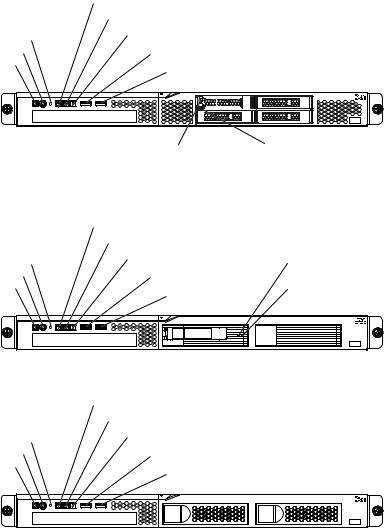
The following illustration shows the 2.5-inch hot-swap SAS server model.
1. Racks are marked in vertical increments of 1.75 inches each. Each increment is referred to as a unit, or a “U”. A 1U-high device is approximately 1.75 inches tall.
© Copyright IBM Corp. 2010 |
1 |
|
Hard disk drive activity LED |
|||||
|
Locator LED |
|||||
Reset button |
System-error LED |
|||||
|
|
|
|
|
||
Power-control button |
USB 1 connector |
|||||
Power-on LED |
||||||
USB 2 connector |
||||||
|
||||||
|
|
|
|
|
|
|
|
|
|
|
|
|
|
|
|
|
|
|
|
|
|
|
|
|
|
|
|
|
|
|
|
|
|
|
|
|
|
|
|
|
|
Hard disk drive activity |
Hard disk drive status |
LED (green) |
LED (amber) |
The following illustration shows the 3.5-inch hot-swap SAS/SATA server model.
|
Hard disk drive activity LED |
|
|
|
Locator LED |
|
|
Reset button |
System-error LED |
|
Hard disk drive activity |
Power-control button |
USB 1 connector |
|
LED (green) |
Power-on LED |
|
Hard disk drive status |
|
USB 2 connector |
|
||
|
|
LED (amber) |
|
|
|
|
|
|
|
|
|
|
|
|
|
The following illustration shows the 3.5-inch simple-swap SATA server model.
|
Hard disk drive activity LED |
|
|
Locator LED |
|
Reset button |
System-error LED |
|
|
||
Power-control button |
USB 1 connector |
|
Power-on LED |
||
USB 2 connector |
||
|
If firmware and documentation updates are available, you can download them from the IBM Web site. The server might have features that are not described in the documentation that comes with the server, and the documentation might be updated occasionally to include information about those features, or technical updates might be available to provide additional information that is not included in the server documentation. To check for updates, complete the following steps.
Note: Changes are made periodically to the IBM Web site. Procedures for locating firmware and documentation might vary slightly from what is described in this document.
1.Go to http://www.ibm.com/systems/support/.
2.Under Product support, click System x.
3.Under Popular links, click Software and device drivers for firmware updates, or click Publications lookup for documentation updates.
2 IBM System x3250 M3 Types 4251, 4252, and 4261: Installation and User’s Guide

Record information about the server in the following table.
Product name |
IBM System x3250 M3 server |
Machine type |
4251, 4252, or 4261 (circle the machine type that applies) |
Model number |
_____________________________________________ |
Serial number |
_____________________________________________ |
|
|
The model number and serial number are on the ID label on the front of the server.
ID label 
Note: The illustrations in this document might differ slightly from your hardware.
You can download an IBM ServerGuide Setup and Installation CD to help you configure the hardware, install device drivers, and install the operating system.
For a list of supported optional devices for the server, see http://www.ibm.com/ servers/eserver/serverproven/compat/us/.
See the Rack Installation Instructions document on the IBM System x
Documentation CD for complete rack installation and removal instructions.
The IBM System x Documentation CD
The IBM System x Documentation CD contains documentation for the server in Portable Document Format (PDF) and includes the IBM Documentation Browser to help you find information quickly.
Hardware and software requirements
The IBM System x Documentation CD requires the following minimum hardware and software:
vMicrosoft Windows XP, Windows 2000, or Red Hat Linux
v100 MHz microprocessor
v32 MB of RAM
vAdobe Acrobat Reader 3.0 (or later) or xpdf, which comes with Linux operating systems
Using the Documentation Browser
Use the Documentation Browser to browse the contents of the CD, read brief descriptions of the documents, and view documents, using Adobe Acrobat Reader or xpdf. The Documentation Browser automatically detects the regional settings in use in your server and displays the documents in the language for that region (if available). If a document is not available in the language for that region, the English-language version is displayed.
Chapter 1. The System x3250 M3 server 3

Use one of the following procedures to start the Documentation Browser:
vIf Autostart is enabled, insert the CD into the CD or DVD drive. The Documentation Browser starts automatically.
vIf Autostart is disabled or is not enabled for all users, use one of the following procedures:
–If you are using a Windows operating system, insert the CD into the CD or DVD drive and click Start -> Run. In the Open field, type
e:\win32.bat
where e is the drive letter of the CD or DVD drive, and click OK.
–If you are using Red Hat Linux, insert the CD into the CD or DVD drive; then, run the following command from the /mnt/cdrom directory:
sh runlinux.sh
Select the server from the Product menu. The Available Topics list displays all the documents for the server. Some documents might be in folders. A plus sign (+) indicates each folder or document that has additional documents under it. Click the plus sign to display the additional documents.
When you select a document, a description of the document is displayed under Topic Description. To select more than one document, press and hold the Ctrl key while you select the documents. Click View Book to view the selected document or documents in Acrobat Reader or xpdf. If you selected more than one document, all the selected documents are opened in Acrobat Reader or xpdf.
To search all the documents, type a word or word string in the Search field and click Search. The documents in which the word or word string appears are listed in order of the most occurrences. Click a document to view it, and press Crtl+F to use the Acrobat search function, or press Alt+F to use the xpdf search function within the document.
Click Help for detailed information about using the Documentation Browser.
Related documentation
This Installation and User’s Guide contains general information about the server including how to set up and cabling the server, how to install supported optional devices, and how to configure the server. The following documentation also comes with the server:
vProblem Determination and Service Guide
This document is in PDF on the IBM System x Documentation CD. It contains information to help you solve problems yourself, and it contains information for service technicians.
vWarranty Information
This printed document contains information about the terms of the warranty.
vRack Installation Instructions
This printed document contains instructions for installing the server in a rack and comes with the rack kit.
vIBM Environmental Notices and User Guide
This document is in PDF format on the IBM System x Documentation CD. It contains translated environmental notices.
vSafety Information
4 IBM System x3250 M3 Types 4251, 4252, and 4261: Installation and User’s Guide

This document is in PDF on the IBM System x Documentation CD. It contains translated caution and danger statements. Each caution and danger statement that appears in the documentation has a number that you can use to locate the corresponding statement in your language in the Safety Information document.
Depending on the server model, additional documentation might be included on the IBM System x Documentation CD.
The System x and BladeCenter Tools Center is an online information center that contains information about tools for updating, managing, and deploying firmware, device drivers, and operating systems. The System x and BladeCenter Tools Center is at http://publib.boulder.ibm.com/infocenter/toolsctr/v1r0/index.jsp.
The server might have features that are not described in the documentation that you received with the server. The documentation might be updated occasionally to include information about those features, or technical updates might be available to provide additional information that is not included in the server documentation. These updates are available from the IBM Web site. To check for updates, complete the following steps.
Note: Changes are made periodically to the IBM Web site. The actual procedure might vary slightly from what is described in this document.
1.Go to http://www.ibm.com/systems/support/.
2.Under Product support, click System x.
3.Under Popular links, click Publications lookup.
4.From the Product family menu, select System x3250 M3 and click Go.
Notices and statements in this document
The caution and danger statements in this document are also in the multilingual
Safety Information document, which is on the IBM System x Documentation CD. Each statement is numbered for reference to the corresponding statement in your language in the Safety Information document.
The following notices and statements are used in this document:
vNote: These notices provide important tips, guidance, or advice.
vImportant: These notices provide information or advice that might help you avoid inconvenient or problem situations.
vAttention: These notices indicate potential damage to programs, devices, or data. An attention notice is placed just before the instruction or situation in which damage might occur.
vCaution: These statements indicate situations that can be potentially hazardous to you. A caution statement is placed just before the description of a potentially hazardous procedure step or situation.
vDanger: These statements indicate situations that can be potentially lethal or extremely hazardous to you. A danger statement is placed just before the description of a potentially lethal or extremely hazardous procedure step or situation.
Chapter 1. The System x3250 M3 server 5

Features and specifications
The following information is a summary of the features and specifications of the server. Depending on the model, some features might not be available, or some specifications might not apply.
Table 1. Features and specifications
Microprocessor:
vSupports one Intel quad-core (Xeon 3400 series) or dual-core (Celeron G1101, Pentium G6950, or Core i3 series) processor the IbexPeak 3420 chip set and Multi-chip Package (MCP) processor architecture
vDesigned for LGA 1156 socket
vScalable up to four cores
v32 KB instruction cache, 32 KB data cache, and up to 8 MB L3 cache that is shared among the cores
vSupport for Intel Extended Memory 64 Technology (EM64T)
Note:
vUse the Setup utility to determine the type and speed of the microprocessor.
vFor a list of supported microprocessors, see http://www.ibm.com/servers/eserver/ serverproven/compat/us/.
Memory:
vMinimum: 1 GB
vMaximum: 32 GB
–16 GB using unbuffered DIMMs (UDIMMs)
–32 GB using registered DIMMs (RDIMMs)
vTypes: PC3-8500 or PC3-10600R-999 (single-rank or double-rank), 1066, and 1333 MHz, ECC, DDR3 registered or unbuffered SDRAM DIMMs only
vConnectors: Six dual inline memory module (DIMM) connectors, two-way interleaved
vSupports (depending on the model):
–1 GB, 2 GB, and 4 GB unbuffered DIMMS
–1 GB, 2 GB, 4 GB, and 8 GB registered DIMMs
SATA optical drives:
vUltraSlim DVD-ROM combo (optional)
vMulti-burner (optional)
Hard disk drive expansion bays (depending on the model):
One of the following configurations:
vFour 2.5-inch hot-swap SAS hard disk drive bays
vTwo 3.5-inch hot-swap SAS or hot-swap SATA hard disk drive bays
vTwo 3.5-inch simple-swap SAS or simple-swap SATA hard disk drive bays
Note:
–Simple-swap SATA hard disk drives support AHCI mode.
–Simple-swap models only support ServeRAID-BR10il adapter.
PCI expansion slots:
Supports two PCI riser slots on the riser card that connects to slots 1 and 2 on the system board:
vSlot 1 supports low-profile cards (PCI Express Gen2 x8
vSlot 2 supports 3/4-length, full-height cards (PCI Express Gen2 x8 or PCI-X 1.0a 64-bit/133 MHz)
Power supply:
One 351-watt power supply or one 351-watt high efficiency power supply with Active Energy Manager (AEM) depending on your model.
Fans: The server comes standard with five speed-controlled fans.
Integrated functions:
vIntegrated management module (IMM), which provides service processor control and monitoring functions, video controller, and (when the optional virtual media key is installed) remote keyboard, video, mouse, and remote hard disk drive capabilities
vIntel 82574L Gb Ethernet controller with TCP/IP Offload Engine (TOE) and Wake on LAN support
vSeven Universal Serial Bus (USB) 2.0 ports (two front, four rear, and one internal for the optional USB Hypervisor key)
vTwo Ethernet ports
vFour-port integrated SATA controller
vIntegrated Trusted Platform Module (TPM) support
vOne serial port
vOne VGA port
6 IBM System x3250 M3 Types 4251, 4252, and 4261: Installation and User’s Guide
Table 1. Features and specifications (continued)
RAID controllers:
vA ServeRAID-BR10il v2 SAS/SATA adapter that provides RAID levels 0, 1, and 1E (comes standard on some hot-swap SAS and hot-swap SATA models).
vAn optional ServeRAID-MR10i SAS/SATA adapter that provides RAID levels 0, 1, 5, 6, and 10 can be ordered.
vAn optional ServeRAID-MR10is VAULT SAS/SATA adapter with an encryption 1078 DE chip set that provides RAID levels 0, 1, 5, 6, and 10 can be ordered.
Acoustical noise emissions:
vSound power, idling: 6.5 bels maximum
vSound power, operating: 6.5 bels maximum
Environment:
vAir temperature:
–Server on: 10°C to 35°C (50.0°F to 95.0°F); altitude: 0 to 914.4 m (3000 ft)
–Server on: 10°C to 32°C (50.0°F to 89.6°F); altitude: 914.4 m (3000 ft) to 2133.6 m (7000.0 ft)
–Server off: 10°C to 43°C
(50°F to 109.4°F); maximum altitude: 2133.6 m (7000.0 ft)
–Shipping: -40°C to 60°C (-104°F to 140°F)
vHumidity:
–Server on: 8% to 80%
–Server off: 8% to 80%
vParticulate contamination:
Attention: Airborne particulates and reactive gases acting alone or in combination with other environmental factors such as humidity or temperature might pose a risk to the server. For information about the limits for particulates and gases, see “Particulate contamination” on page 79.
Video controller (integrated into IMM):
vMatrox G200
vSVGA compatible video controller
vAvocent Digital Video Compression
vVideo memory is not expandable
Note: The maximum video resolution is 1280 x 1024
Size:
vHeight: 43 mm (1.69 inches, 1 U)
vDepth: 559 mm (22 inches)
vWidth: 440 mm (17.32 inches)
vMaximum weight: 12.7 kg (28 lb)
Heat output:
Approximate heat output:
vMinimum configuration: 171 BTU per hour (50 watts)
vMaximum configuration: 1024 BTU per hour (300 watts)
Electrical input:
vSine-wave input (50 / 60 Hz) required
vInput voltage low range:
–Minimum: 100 V ac
–Maximum: 127 V ac
vInput voltage high range:
–Minimum: 200 V ac
–Maximum: 240 V ac
vInput kilovolt-amperes (kVA), approximately:
–Minimum: 0.102 kVA
–Maximum: 0.55 kVA
Notes:
1.Power consumption and heat output vary depending on the number and type of optional features installed and the power-management optional features in use.
2.The sound levels were measured in controlled acoustical environments according to the procedures specified by the American National Standards Institute (ANSI) S12.10 and ISO 7779 and are reported in accordance with ISO 9296. Actual sound-pressure levels in a given location might exceed the average values stated because of room reflections and other nearby noise sources. The noise emission level stated in the declared (upper limit) sound-power level, in bels, for a random sample of system.
3.There is no keyboard connector or mouse connector on the server. You can connect a USB keyboard and USB mouse to the server by using the USB connectors.
Chapter 1. The System x3250 M3 server 7

What your server offers
The server uses the following features and technologies:
vIntegrated management module
The Integrated management module (IMM) combines service processor functions, video controller, and (when an optional virtual media key is installed) remote presence function in a single chip. The IMM provides advanced service-processor control, monitoring, and alerting function. If an environmental condition exceeds a threshold or if a system component fails, the IMM lights LEDs to help you diagnose the problem, records the error in the event log, and alerts you to the problem. Optionally, the IMM also provides a virtual presence capability for remote server management capabilities. The IMM provides remote server management through the following industry-standard interfaces:
–Intelligent Platform Management Interface (IPMI) version 2.0
–Simple Network Management Protocol (SNMP) version 3
–Common Information Model (CIM)
–Web browser
For additional information, see “Using the integrated management module” on page 66.
vUEFI-compliant server firmware
The IBM System x Server Firmware offers several features, including Unified Extensible Firmware Interface (UEFI) version 2.1 compliance, Active Energy Manager (AEM) technology, enhanced reliability, availability and serviceability (RAS) capabilities, and basic input/output system (BIOS) compatibility support. UEFI replaces the legacy BIOS. UEFI defines a standard interface between the operating system, platform firmware and external devices, and offers capabilities that far exceeds that of the legacy BIOS.
The server design combines the UEFI capabilities and features with legacy BIOS compatibility. The server is capable of booting UEFI-compliant operating systems, BIOS-based operating systems, and BIOS-based adapters as well as UEFI-compliant adapters.
vIBM Dynamic System Analysis Preboot diagnostics programs
The Dynamic System Analysis (DSA) Preboot diagnostics programs are stored on the integrated USB memory. It collects and analyzes system information to aid in diagnosing server problems. The diagnostic programs collect the following information about the server:
–System configuration
–Network interfaces and settings
–Installed hardware
–Service processor status and configuration
–Vital product data, firmware, and UEFI (formerly BIOS) configuration
–Hard disk drive health
–RAID controller configuration
–Event logs for ServeRAID controllers and service processors
The diagnostic programs create a merged log that includes events from all collected logs. The information is collected into a file that you can send to IBM service and support. Additionally, you can view the information locally through a generated text report file. You can also copy the log to a removable media and view the log from a Web browser.
8 IBM System x3250 M3 Types 4251, 4252, and 4261: Installation and User’s Guide
For additional information about DSA Preboot diagnostics, see the Problem Determination and Service Guide on the IBM System x Documentation CD
vDual-core or quad-core processing
The server supports one Intel Xeon dual-core or quad-core microprocessor.
vIBM Systems Director CD
IBM Systems Director is a workgroup-hardware-management tool that you can use to centrally manage System x and xSeries servers. For more information, see the IBM Systems Director documentation on the IBM Systems Director CD and “IBM Systems Director” on page 12.
vIBM X-Architecture technology
IBM X-Architecture technology combines proven, innovative IBM designs to make your Intel-processor-based server powerful, scalable, and reliable. For more information, see http://www.ibm.com/servers/eserver/xseries/xarchitecture/ enterprise/index.html.
–VMware ESXi embedded hypervisor
The VMware ESXi embedded hypervisor is available on some server models. Hypervisor is virtualization software that enables multiple operating systems to run on a host system at the same time. The VMware ESXi embedded hypervisor software is provided on USB flash device that is installed in the USB connector on the system board. See “Using the embedded hypervisor” on page 67 for additional information.
–Remote presence capability and blue-screen capture
The remote presence and blue-screen capture features are integrated functions of the integrated management module (IMM) and are available with the purchase of the optional IBM Virtual Media Key. A virtual media key is required to enable the remote presence and blue-screen capture features. The remote presence feature provides the following functions:
-Remotely viewing video with graphics resolutions up to 1280 x 1024, regardless of the system state
-Remotely accessing the server, using the keyboard and mouse from a remote client
-Mapping the DVD drive, diskette drive, and USB flash drive on a remote client, and mapping ISO and diskette image files as virtual drives that are available for use by the server
-Uploading a diskette image to the IMM memory and mapping it to the server as a virtual drive
The blue-screen capture feature captures the video display contents before the IMM restarts the server when the IMM detects an operating-system hang condition. A system administrator can use the blue-screen capture to assist in determining the cause of the hang condition.
See “Using the remote presence capability and blue-screen capture” on page 68 for additional information.
–Large system-memory capacity
The memory bus supports up to 32 GB of memory when registered DIMMs are installed. The server supports up to 16 GB if unbuffered DIMMs are installed. The memory controller supports error correcting code (ECC) for up to six industry-standard PC3-8500 or PC3-10600R-999, 1066 and 1333 MHz, DDR3 (third-generation double-data-rate), registered or unbuffered, synchronous dynamic random access memory (SDRAM) dual inline memory modules (DIMMs).
v IBM ServerGuide Setup and Installation CD
Chapter 1. The System x3250 M3 server 9
The ServerGuide Setup and Installation CD, which you can download from the Web, provides programs to help you set up the server and install a Windows operating system. The ServerGuide program detects installed optional hardware devices and provides the correct configuration programs and device drivers. For more information about the ServerGuide Setup and Installation CD, see “Using the ServerGuide Setup and Installation CD” on page 64.
vIntegrated network support
The server comes with an integrated Intel Gigabit Ethernet controller, which supports connection to a 10 Mbps, 100 Mbps, or 1000 Mbps network. For more information, see “Configuring the Gigabit Ethernet controller” on page 70.
vIntegrated Trusted Platform Module (TPM)
This integrated security chip performs cryptographic functions and stores private and public secure keys. It provides the hardware support for the Trusted Computing Group (TCG) specification. You can download the software to support the TCG specification, when the software is available. See http://www.ibm.com/ servers/eserver/xseries/scalable_family.html for details about the TPM implementation. You can enable TPM support through the Setup utility under the
System Security menu choice.
vActive Energy Manager (AEM)
The IBM Active Energy Manager solution is an IBM Systems Director plug-in that measures and reports server power consumption as it occurs. This enables you to monitor power consumption in correlation to specific software application programs and hardware configurations. You can obtain the measurement values through the systems-management interface and view them, using IBM Systems Director. For more information, including the required levels of IBM Systems Director and Active Energy Manager, see the IBM Systems Director documentation on the IBM Systems Director CD, or see http://www.ibm.com/ systems/management/director/resources/.
vLarge data-storage capacity and hot-swap capability
The server supports a maximum of four 2.5-inch hot-swap Serial Attached SCSI (SAS) hard disk drives, two 3.5-inch simple-swap Serial ATA (SATA) hard disk drives, or two 3.5-inch hot-swap SAS or SATA hard disk drives, depending on the server model.
With the hot-swap feature, you can add, remove, or replace hard disk drives without turning off the server.
vPCI adapter capabilities
The server has two PCI interface slots on the riser card (one supports low-profile cards, and one supports full-height, three-quarter length cards). Both slots can support PCI Express or PCI-X adapters. See “Installing an adapter” on page 41 for detailed information.
vServeRAID support
The ServeRAID adapter provides hardware redundant array of independent disks (RAID) support to create configurations. The standard RAID adapter provides RAID levels 0, 1, and 1E. An optional RAID adapter is available for purchase that provides RAID levels 0, 1, 5, 6, and 10.
vSystems-management capabilities
The server comes with an integrated management module (IMM). When the IMM is used with the systems-management software that comes with the server, you can manage the functions of the server locally and remotely. The IMM also provides system monitoring, event recording, and network alert capability.
vTCP/IP offload engine (TOE) support
10 IBM System x3250 M3 Types 4251, 4252, and 4261: Installation and User’s Guide

The Ethernet controllers in the server support TOE, which is a technology that offloads the TCP/IP flow from the microprocessor and I/O subsystem to increase the speed of the TCP/IP flow. When an operating system that supports TOE is running on the server and TOE is enabled, the server supports TOE operation. See the operating-system documentation for information about enabling TOE.
Note: As of the date of this document, the Linux operating system does not support TOE.
Reliability, availability, and serviceability
Three important computer design features are reliability, availability, and serviceability (RAS). The RAS features help to ensure the integrity of the data that is stored in the server, the availability of the server when you need it, and the ease with which you can diagnose and correct problems.
Your server has the following RAS features:
v1-year parts and 1-year labor limited warranty for machine type 4251, 3-year parts and 3-year labor limited warranty for machine type 4252, and 4-year parts and 4-year labor limited warranty for machine type 4261.
vAutomatic error retry and recovery
vAutomatic restart on nonmaskable interrupt (NMI)
vAutomatic restart after a power failure
vAdvanced Configuration and Power Interface (ACPI)
vAdvanced Desktop Management Interface (DMI) features
vIntelligent Platform Management Interface (IPMI) 2.0 support that provides secure remote power on/power off and seven standard alerts for components such as fans, voltage, and thermals
vAuto-restart initial program load (IPL)
vBoot-block recovery
vBuilt-in, menu-driven configuration and setup programs
vBackup basic input/output system switching under the control of the integrated management module (IMM)
vBuilt-in monitoring for fan, power, temperature, voltage, and power supply
vDiagnostic support for ServeRAID and Ethernet adapters
vECC memory
vError codes and messages
vHot-swap hard disk drives
vIntegrated management module (IMM)
vMenu-driven setup, system configuration, and redundant array of independent disks (RAID) configuration programs
vParity checking on the small computer system interface (SCSI) bus and PCI buses
vPower management: Compliance with Advanced Configuration and Power Interface (ACPI)
vPower-on self-test (POST)
vPredictive Failure Analysis (PFA) alerts on memory, SAS/SATA hard disk drives, fans, and power supplies
vRemote system problem-determination support
vRead-only memory (ROM) checksums
vROM-based diagnostics
vSDRAM with serial presence detect (SPD)
vSerial Presence Detection (SPD) on memory, VPD, power supply, and hard disk drives backplane
vSingle-DIMM isolation of excessive correctable error or multi-bit error by the Unified Extensible Firmware Interface (UEFI)
Chapter 1. The System x3250 M3 server 11

vStandby voltage for system-management features and monitoring
vStartup (boot) from LAN through remote initial program load (RIPL) or dynamic host configuration protocol/boot protocol (DHCP/BOOTP)
vSystem auto-configuring from the configuration menu
vSystem-error logging (POST and IMM)
vSystems-management monitoring through the Inter-Integrated Circuit (IC) protocol bus
vUpgradeable POST, Unified Extensible Firmware Interface (UEFI), diagnostics, IMM firmware, and read-only memory (ROM) resident code, locally or over the LAN
vVital product data (VPD) on microprocessor, system board, power supply, and SAS/SATA (hot-swap hard disk drive) backplane
vWake on LAN capability
IBM Systems Director
IBM Systems Director is a platform-management foundation that streamlines the way you manage physical and virtual systems and supports multiple operating systems and virtualization technologies in IBM and non-IBM x86 platforms.
Through a single user interface, IBM Systems Director provides consistent views for viewing managed systems, determining how these systems relate to one another, and identifying their statuses, helping to correlate technical resources with business needs. A set of common tasks that are included with IBM Systems Director provides many of the core capabilities that are required for basic management, which means instant out-of-the-box business value. The following common tasks are included:
vDiscovery
vInventory
vConfiguration
vSystem health
vMonitoring
vUpdates
vEvent notification
vAutomation for managed systems
The IBM Systems Director Web and command-line interfaces provide a consistent interface that is focused on driving these common tasks and capabilities:
vDiscovering, navigating, and visualizing systems on the network with the detailed inventory and relationships to the other network resources
vNotifying users of problems that occur on systems and the ability to isolate the sources of the problems
vNotifying users when systems need updates and distributing and installing updates on a schedule
vAnalyzing real-time data for systems and setting critical thresholds that notify the administrator of emerging problems
vConfiguring settings of a single system and creating a configuration plan that can apply those settings to multiple systems
vUpdating installed plug-ins to add new features and functions to the base capabilities
vManaging the life cycles of virtual resources
12 IBM System x3250 M3 Types 4251, 4252, and 4261: Installation and User’s Guide

For more information about IBM Systems Director, see the documentation on the IBM Systems Director CD that comes with the server and the IBM xSeries Systems Management Web page at http://www.ibm.com/systems/management/, which presents an overview of IBM Systems Management and IBM Systems Director.
The UpdateXpress System Packs
The UpdateXpress System Packs provide an effective and simple way to update device drivers, server firmware, and firmware of supported options contained within the server, for System x and IBM BladeCenter® servers. Each UpdateXpress System Pack contains all the online driver and firmware updates for a specific machine type and operating system combination. The UpdateXpress System Packs are released quarterly. Use the UpdateXpress System Pack Installer to install the current UpdateXpress System Pack for your server. You can download the installer and the latest UpdateXpress System Pack for your server from the Web at no additional cost. To download the installer or the latest UpdateXpress System Pack, go to http://www.ibm.com/systems/support/supportsite.wss/ docdisplay?lndocid=SERV-XPRESS&brandind=5000008 or complete the following steps.
Note: Changes are made periodically to the IBM Web site. The actual procedure might vary slightly from what is described in this document.
1.Go to http://www.ibm.com/systems/support/.
2.Under Product support, click System x.
3.Under Popular links, click Software and device drivers.
4.Under Related downloads, click UpdateXpress.
Server controls, LEDs, and power
This section describes the controls and light-emitting diodes (LEDs) and how to turn the server on and off. For the locations of other LEDs on the system board, see “System-board LEDs” on page 24.
Front view
The following illustrations show the controls, LEDs, and connectors on the front of the hot-swap 3.5-inch hard disk drive model.
|
Hard disk drive activity LED |
|
|
|
Locator LED |
|
|
Reset button |
System-error LED |
|
Hard disk drive activity |
Power-control button |
USB 1 connector |
|
LED (green) |
Power-on LED |
|
Hard disk drive status |
|
USB 2 connector |
|
||
|
|
LED (amber) |
|
|
|
|
|
|
|
|
|
|
|
|
|
The following illustration shows the controls, LEDs, and connectors on the front of the simple-swap 3.5-inch hard disk drive model.
Chapter 1. The System x3250 M3 server 13

|
Hard disk drive activity LED |
|
|
Locator LED |
|
Reset button |
System-error LED |
|
|
||
Power-control button |
USB 1 connector |
|
Power-on LED |
||
USB 2 connector |
||
|
The following illustration shows the controls, LEDs, and connectors on the front of the hot-swap 2.5-inch hard disk drive model.
|
Hard disk drive activity LED |
||||||||||
|
Locator LED |
||||||||||
Reset button |
System-error LED |
||||||||||
|
|
|
|
|
|
|
|
|
|
||
Power-control button |
USB 1 connector |
||||||||||
Power-on LED |
|||||||||||
USB 2 connector |
|||||||||||
|
|||||||||||
|
|
|
|
|
|
|
|
|
|
|
|
|
|
|
|
|
|
|
|
|
|
|
|
|
|
|
|
|
|
|
|
|
|
|
|
|
|
|
|
|
|
|
|
|
|
|
|
Hard disk drive activity |
Hard disk drive status |
LED (green) |
LED (amber) |
v Power-on LED: The states of the power-on LED are as follows:
Off: AC power is not present, or the power supply or the LED itself has failed.
Flashing rapidly (4 times per second): The server is turned off and is not ready to be turned on. The power-control button is disabled. This will last approximately 1 to 3 minutes.
Flashing slowly (once per second): The server is turned off and is ready to be turned on. You can press the power-control button to turn on the server.
Lit: The server is turned on.
Fading on and off: The server is in a reduced-power state. To wake the server, press the power-control button or use the IMM Web interface. See “Logging on to the Web interface” on page 69 for information on logging on to the IMM Web interface.
vPower-control button: Press this button to turn the server on and off manually or to wake the server from a reduced-power state.
vReset button: Press this button to reset the server and run the power-on self-test (POST). You might have to use a pen or the end of a straightened paper clip to press the button.
vHard disk drive activity LEDs: When this LED is flashing, it indicates that the associated hard disk drive is in use.
vLocator LED: Use this blue LED to visually locate the server among other servers. This LED is also used as a presence detection button. You can use IBM Systems Director to light this LED remotely. This LED is controlled by the IMM.
vSystem-error LED: When this amber LED is lit, it indicates that a system error has occurred.
vUSB connectors: Connect a USB device, such as a USB mouse, keyboard, or other device to any of these connectors.
vOptional DVD eject button: Press this button to release a DVD or CD from the optional DVD drive.
14 IBM System x3250 M3 Types 4251, 4252, and 4261: Installation and User’s Guide

vOptional DVD drive activity LED: When this LED is lit, it indicates that the optional DVD drive is in use.
vHot-swap hard disk drive activity LEDs (some models): This LED is used on SAS or SATA hard disk drives. Each hot-swap hard disk drive has an activity LED, and when this LED is flashing, it indicates that the drive is in use.
vHot-swap hard disk drive status LEDs (some models): This LED is used on SAS or SATA hard disk drives. When this LED is lit, it indicates that the drive has failed. If an optional IBM ServeRAID controller is installed in the server, when this LED is flashing slowly (one flash per second), it indicates that the drive is being rebuilt. When the LED is flashing rapidly (three flashes per second), it indicates that the controller is identifying the drive.
Rear view
The following illustration shows the LEDs and connectors on the rear of the server.
Note: The illustrations in this document might differ slightly from your hardware.
|
|
Ethernet 1 |
Ethernet 1 |
Ethernet 2 |
|
|
|
activity LED link LED |
activity LED |
|
|
|
Power-cord |
Serial |
|
Ethernet 2 PCI slot 1 |
PCI slot 2 |
|
connector |
connector |
|
||
|
|
link LED |
|
||
|
|
|
|
|
|
AC Power LED |
|
|
|
NMI button |
|
(green) |
|
|
USB 3-4 connector |
|
|
|
|
|
|
||
DC Power LED |
Power supply |
Video |
USB 1-2 connector |
|
|
(green) |
|
||||
error LED |
connector |
|
|
||
|
|
|
|||
(amber)
vEthernet link LEDs: When these LEDs are lit, they indicate that there is an active link connection on the 10BASE-T, 100BASE-TX, or 1000BASE-TX interface for the Ethernet port.
vEthernet activity LEDs: When these LEDs are lit, they indicate that there is activity between the server and the network.
vAC power LED (some models): This LED is used on power supply with Active Energy Manager (AEM). This green LED provides status information about the power supply. During typical operation, both the ac and dc power LEDs are lit. For any other combination of LEDs, see the Problem Determination and Service Guide on the IBM System x Documentation CD.
vDC power LED (some models): This LED is use on power supply with AEM. This green LED provides status information about the power supply. During typical operation, both the ac and dc power LEDs are lit. For any other combination of LEDs, see the Problem Determination and Service Guide on the IBM System x Documentation CD.
vPower-error (!) LED (some models): This LED is use on power supply with AEM. When this amber LED is lit, it indicates that the power supply has failed. For any other combination of LEDs, see the Problem Determination and Service Guide on the IBM System x Documentation CD.
vPower cord connector: Connect the power cord to this connector.
vVideo connector: Connect a monitor to this connector.
Chapter 1. The System x3250 M3 server 15
vSerial connector: Connect a 9-pin serial device to this connector. The serial port is shared with the integrated management module (IMM). The IMM can take control of the shared serial port to redirect serial traffic, using Serial over LAN (SOL).
vUSB connectors: Connect a USB device, such as a USB mouse, keyboard, or other device to any of these connectors.
vEthernet connectors: Use either of these connectors to connect the server to a network. When you use the Ethernet 1 connector, the network can be shared with the IMM through a single network cable.
vNMI button: Press this button to force a nonmaskable interrupt to the microprocessor. You might have to use a pen or the end of a straightened paper clip to press the button. It allows you to blue screen the server and take a memory dump (use this button only when directed by the IBM service support).
vPCI slot 1: Insert a low-profile PCI Express or PCI-X adapter into this slot. Standard models of the server come with two PCI Express riser assemblies. You can purchase an optional PCI-X riser-card assembly with bracket if you want to install a PCI-X adapter in this slot.
vPCI slot 2: Insert a three-quarter length, full-height PCI Express or PCI-X adapter into this slot. Standard models of the server come with two PCI Express riser assemblies. You can purchase an optional PCI-X riser-card assembly with bracket if you want to install a PCI-X adapter in this slot.
Server power features
When the server is connected to an ac power source but is not turned on, the operating system does not run, and all core logic except for the service processor (the integrated management module) is shut down; however, the server can respond to requests to the service processor, such as a remote request to turn on the server. The power-on LED flashes to indicate that the server is connected to ac power but is not turned on.
Turning on the server
Approximately 5 seconds after the server is connected to ac power, one or more fans might start running to provide cooling while the server is connected to power and the power-on button LED flashes quickly. Approximately 1 to 3 minutes after the server is connected to ac power, the power-control button becomes active (the power-on LED flashes slowly), and one or more fans might start running to provide cooling while the server is connected to power. You can turn on the server by pressing the power-control button.
The server can also be turned on in any of the following ways:
vIf a power failure occurs while the server is turned on, the server will restart automatically when power is restored.
vIf your operating system supports the Wake on LAN feature, the Wake on LAN feature can turn on the server.
Note: When 4 GB or more of memory (physical or logical) is installed, some memory is reserved for various system resources and is unavailable to the operating system. The amount of memory that is reserved for system resources depends on the operating system, the configuration of the server, and the configured PCI devices.
Turning off the server
When you turn off the server and leave it connected to ac power, the server can respond to requests to the service processor, such as a remote request to turn on
16 IBM System x3250 M3 Types 4251, 4252, and 4261: Installation and User’s Guide
Loading...