

Page 1

F
EDERAL
C
OMMISSION
C
OMMUNICATIONS
(FCC) W
ARNING
Instruction to Users
This equipment has been tested and found to comply
with the limits for a Class B digital device, pursuant
to part 15 of the FCC rules. These limits are designed
to provide reasonable protection against harmful interference in a residential installation. This equipment
generates, uses and can radiate radio frequency energy
and, if not installed and used in accordance with the
instructions, may cause harmful interference to radio
communications. However, there is no guarantee that
interference will not occur in a particular installation.
If this equipment does cause harmful interference to
radio and television reception, which can be
determined by turning the equipment off and on, the
user is encouraged to try to correct the interference
by one or more of the following measures.
- Reorient or relocate the receiving antenna.
- Increase the separation between the equipment
and the receiver.
- Connect the equipment into an outlet on a circuit different from that to which the receiver is
connected.
- Consult the dealer or an experienced radio/ TV
technician for help.
E-1
DOC N
This product conforms to Canadian Class B emissions
regulations.
Ce produit est conforme aux réglements d’émission
Canadienne class B.
OTICE
This equipment has been certified to comply with the
limits for a Class B computing device, pursuant to
part 15 of the FCC rules. Only peripherals (computer
input / output devices, terminals, printers etc.) certified
to comply to the Class B limits may be attached to
this computer. Operation with non-certified
peripherals is likely to result in interference to radio
and TV reception.
Remarks
To meet FCC requirement, shielded cables are required
to connect the device to a personal computer or other
Class B certified device.
Information to Users
Any change or modifications expressly approved by
the party responsible for compliance could void the
user's authority to operate this equipment.
Page 2
E-2
INTRODUCTION
This microprocessor-based, digital control 15” color
monitor is a high performance and easy to use product.
It employs the latest on-screen-menu technology. The
microprocessor capability offers 12 most commonly
used VESA timing modes preset in the factory, and 6
modes for user to adjust to the special timings that
user might have.
We hope that you will find this manual is helpful in
obtaining the fullest use of your monitor, and in
ensuring your personal safety during operation.
POWER SAVING
The monitor will be driven to different power saving
states upon receiving
display controller, this meets the EPA
Environment Protection Agency) Energy Star
requirements and reduces power consumption.
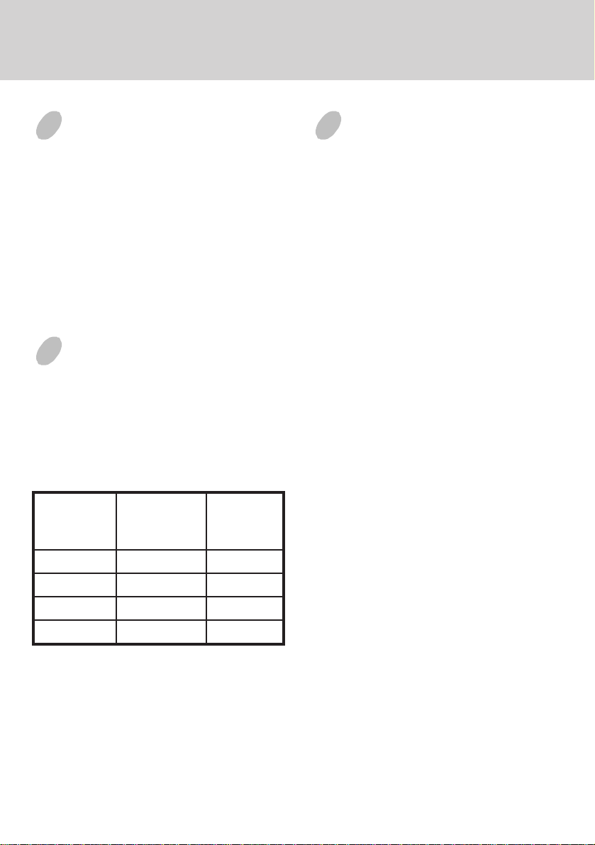
The monitor will work in the following 4 states
according to the VESA standard Display Power
Management Signal:
etatS
control signals from the
rewoP
DEL
noitpmusnoC
thgiL
INSTALL THE
MONITOR
• To connect the tilt/swivel base to the monitor, align
hooks with the sockets on bottom side of the
monitor, and gently push the base towards the front
of the monitor.
• The 15-pin D-shell signal connector on the signal
cable will connect easily to the video adapter
output on your personal computer. Lock both
screws on the connector to ensure a firm
connection.
• Turn the PC power switch ON. Then turn the
monitor power switch ON, by pressing the switch
inward. The green power indicator will light up.
• Allow about 30 seconds for the CRT tube to warm
up. Data will be displayed on the screen.
(
• If your display fails to function properly, please
first refer to the section "Troubleshooting" in this
manual.
NOlamroNneerG
YBDNATSW51<wolleY
DNEPSUSW51<wolleY
FFOW8<rebmA
The power saving states will be kept until a control
signal has been detected or the keyboard or mouse is
activated. The recovery time from STANDBY/
SUSPEND state to ON state shall be within 3 seconds.
It will take about less than 15 seconds from OFF state
back to ON state.
Page 3

USER CONTROLS AND INDICATORS
E-3
1. Press " " button to select control parameters in
sequence as belows
Sequence 1 Contrast
Sequence 2 Brightness
Sequence 3 Horizontal Size
Sequence 4 Horizontal Position
Sequence 5 Vertical Size
Sequence 6 Vertical Centering
Sequence 7 Pincushion/Barrel
Sequence 8 Trapezoid
Then repeat from sequence 1.
Keeping on pressing button continually, the
sequence will repeat automatically.
2. Push “+” or “-” button to adjust the value of the
selected function. When the control value reach
the maximum value (either positive or negative)
the LED will flash, indicating that no more
adjustment value is possible.
RECALL SELECT
3. The “Recall” function is activated by pressing “+”
and “-” buttons at the same time.
4. The manual “Degaussing” function enables user
to clear the picture impurity caused by monitor
position/ orientation change.
When adjustments have been done, all data will be
stored into system memory immediately.
DEG
Page 4

E-4
TROUBLESHOOTING
If your monitor fails to operate functionally, it may
be possible to correct the problem by making simple
checks as follows:
melborPtsujdA&kcehC
neercsknalB
).eton*(
noitisopyalpsiD
retnec-ffo
llamsootyalpsiD
egralootro
thgirbootyalpsiD
midootro
Refer to the operation instructions for your computer/
video adapter to ensure that you have the correct signal
output source for the monitor. Ensure that the switches
on the video adapter are set correctly for operation
with this monitor.
If the above steps fail to correct the problem contact
your dealer for servicing by qualified service
personnel.
Please remember that the monitor should be returned
for servicing together with the power cord.
* Note: You can easily distinguish the problem is on
the monitor or on the computer by using the
monitor’s built-in selftest function.
With the monitor power ON, disconnect the
signal cable from monitor. If there is no image
on the monitor screen, disconnect the signal
cable. If a full-white image is diaplayed on
the screen, the monitor is function properly,
and the problem is at PC side, or signal cable.
rotcennocro
slortnoc
slortnoc
slortnoc
,hctiwsrewoprotinoM
,elbaclangis,drocrewop
hctiwsrewopCP
tsartnoc&ssenthgirB
&gniretneclacitreV
slortnocesahplatnoziroh
ezislatnoziroh&lacitreV
tsartnoc&ssenthgirB
SERVICING
Refer all servicing to qualified service personnel.
Serious shock hazards exist within the covers of
this monitor.
Do not open the covers under any circumstancesthere are no serviceable parts inside.
SIGNAL CONNECTOR
INFORMATION
1
niPnoitcnuFniPnoitcnuF
1langisdeR9CN
2langisneerG01dnuorglatigiD
3langiseulB11dnuorG
4dnuorG21)B2CDD/1CDD(ADS
5* 31
6nruterdeR41
7
8nrutereulB
neerG
nruter
51)B2CDD(LCS
*Note: This pin is used for self test detection; at
PC side, this pin has to be connected to
ground.
5
15
latnoziroH
noitazinorhcnyS
noitazinorhcnyslacitreV
)1CDD(KLCV&
Page 5

TECHNICAL SPECIFICATIONS
lanogaidlausiv"51
eziSneercS
"8.31
ezisneercselbaweiV
gnitaoCeralG-itnA
E-5
tnerruC
gnitaR
A4.1
hctiPtoDmm82.0
aerAyalpsiD
)WxH(
sroloCyalpsiDetinifnIthgieWgk2.21
.xaM
noituloseR
ytilibitapmoC
noitazinorhcnyS
:latnoziroH
:lacitreV
langiStupnI
elbaClangiS
tupnIrewoP
egatloV
ycneuqerF
lacipyt
seniL
latnozirohhtiw
zHK45ot03
zH021ot05
bus-Dnip-51
rotcennoc
CAV042ot001
zH06-05
,)mm(262x691
867xstoD4201
sedomcihpargllA
neewtebseicneuqerf
zHK45otzHK03
golanABGRoediV
etarapeSLTT.cnyS
rewoP
noitpmusnoC
noisnemiD
gnitarepO
erutarepmeT
egarotS
erutarepmeT
ytidimuH
edutitlAtf0007otpU
IIRPM
).XAM(W08
X083X5.573
)mm(883
C53otC01
C56otC0
%08ot%02
)gnisnednoc-non(
,01:0991RPM
noitaidaRwoL
ylnoledom
)lanoitpO(
* Specifications are subject to change without notice.
Page 6

E-6
PRESET MODES
edoM
1053x0274.13077 006x0088.7306
2004x0274.13078 084x0463.3458
3084x0464.13069 006x0088.6457
4006x0081.536501006x0080.8427
5084x0465.735711867x42013.8406
6084x0468.732721006x0086.3558
noituloseR
)VxH(
.qerF.H
)zHK(
.qerF.V
)zH(
edoM
noituloseR
)VxH(
.qerF.H
)zHK(
.qerF.V
)zH(
 Loading...