

Page 1

LenovoC345/C445All-In-OnePC
ideaideaideaCentreidea
HardwareMaintenanceManual
MachineTypes:10103/4751[C345],10105/6596[C445]
Page 2

Page 3

LenovoC345/C445All-In-OnePC
HardwareMaintenanceManual
MachineTypes:10103/4751[C345],10105/6596[C445]
Page 4

ThirdEdition(December2012)28th
©CopyrightLenovo2012.
LIMITEDANDRESTRICTEDRIGHTSNOTICE:IfdataorsoftwarearedeliveredpursuantaGeneralServices
Administration“GSA”contract,use,reproduction,ordisclosureissubjecttorestrictionssetforthinContractNo.
GS-35F-05925
Page 5

Contents
Chapter1.Aboutthismanual......1
ImportantSafetyInformation..........1
Chapter2.Safetyinformation......3
Generalsafety................3
Electricalsafety...............3
Safetyinspectionguide............5
Handlingelectrostaticdischarge-sensitive
devices..................5
Groundingrequirements............6
Safetynotices................6
Chapter3.Generalinformation.....9
Specications................9
Chapter4.GeneralCheckout.....11
Chapter5.UsingtheSetupUtility...13
StartingtheLenovoBIOSSetupUtilityprogram.13
Viewingandchangingsettings........13
Usingpasswords..............13
Enablingordisablingadevice........15
Selectingastartupdevice..........16
ExitingtheLenovoBIOSSetupUtilityprogram..17
Chapter6.Symptom-to-FRUIndex..19
Harddiskdrivebooterror..........19
PowerSupplyProblems...........19
POSTerrorcodes.............20
Undeterminedproblems...........20
Chapter8.Replacinghardware....27
Generalinformation.............27
Replacingthekeyboardandmouse......28
Replacingtheadapter............28
Removingthestandbase..........30
Removingthefootcover...........30
Replacingamemorymodule.........31
Replacingtheharddiskdrive.........33
Replacingtheopticaldrive..........34
Removingthestandholder..........36
Removingthemiddlecover.........37
Replacingtheconverterboard........38
Replacingthecamera............39
RemovingtheEMIcover...........40
ReplacingtherearI/Omodule........41
Replacingthespeakersystem........43
Replacingthesystemfan..........44
Replacingtheheat-sink...........45
ReplacingtheTVtunercard.........46
ReplacingtheWLANcard..........47
Replacingthefrontcontrolboard.......48
Replacingthepowerswitchboard.......49
Replacingthemotherboard..........50
ReplacingtheLEDpanel...........52
Chapter9.FRUlists..........55
Chapter10.Generalinformation...59
AdditionalServiceInformation........59
Chapter7.Locatingconnectors,
controlsandcomponents......21
©CopyrightLenovo2012
iii
Page 6

ivLenovoC345/C445All-In-OnePCHardwareMaintenanceManual
Page 7

Chapter1.Aboutthismanual
ThismanualcontainsserviceandreferenceinformationforLenovoC345andC445All-In-Onecomputers
listedonthecover.ItisintendedonlyfortrainedservicerswhoarefamiliarwithLenovocomputerproducts.
BeforeservicingaLenovoproduct,besuretoreadtheSafetyInformation.
ThedescriptionoftheTV-tunercardinthismanualappliesonlytocomputerswithaTV-tunercardinstalled.
ItdoesnotapplytocomputerswithoutaTV-tunercard.
ImportantSafetyInformation
BesuretoreadallCAUTIONandDANGERsectionsinthismanualbeforefollowinganyoftheinstructions.
VeuillezliretouteslesconsignesdetypeDANGERetATTENTIONduprésentdocumentavantd’exécuter
lesinstructions.
LesenSieunbedingtalleHinweisevomT yp“ACHTUNG”oder“VORSICHT”indieserDokumentation,bevor
SieirgendwelcheVorgängedurchführen
LeggereleistruzioniintrodottedaA TTENZIONEePERICOLOpresentinelmanualeprimadieseguireuna
qualsiasidelleistruzioni
Certique-sedelertodasasinstruçõesdecuidadoeperigonestemanualantesdeexecutarqualquer
umadasinstruções
Esimportantequeleatodaslasdeclaracionesdeprecauciónydepeligrodeestemanualantesdeseguir
lasinstrucciones.
©CopyrightLenovo2012
1
Page 8

2LenovoC345/C445All-In-OnePCHardwareMaintenanceManual
Page 9

Chapter2.Safetyinformation
Thischaptercontainsthesafetyinformationthatyouneedtobefamiliarwithbeforeservicingacomputer.
Generalsafety
Followtheserulestoensuregeneralsafety:
•Keeptheareasaroundthecomputerclearandcleanduringandaftermaintenance.
•Whenliftinganyheavyobject:
1.Ensureyoucanstandsafelywithoutslipping.
2.Distributetheweightoftheobjectequallyacrossbothfeet.
3.Liftslowly.Nevermovesuddenlyortwistwhenyouattempttolift.
4.Liftbystandingorbypushingupwithyourlegmuscles;thisactionremovesthestrainfromthe
musclesinyourback.
Donotattempttoliftanyobjectsthatweighmorethan16kg(35lb)orobjectsthatyouthinkare
tooheavyforyou.
•Donotperformanyactionthatwouldcreateahazardforthecustomer,orwouldmakethecomputer
unsafe.
•Beforeyoustartthecomputer,ensurethatotherservicerepresentativesandcustomerpersonnelarenot
inapositionthatwouldcreateahazardforthem.
•Placeremovedcoversandotherpartsinasafeplace,awayfromallpersonnel,whileyouareservicingthe
computer.
•Keepyourtoolcaseawayfromareasthatpeoplemaywalkthroughtoensureno-onetripsoverit.
•Donotwearlooseclothingthatcanbetrappedinthemovingpartsofamachine.Ensurethatyoursleeves
arefastenedorrolledupaboveyourelbows.Ifyourhairislong,tieorfastenitback.
•Inserttheendsofyournecktieorscarfinsideclothingorfastenitwithanon-conductiveclip,
approximately8centimeters(3inches)fromtheend.
•Donotwearjewelry,chains,metal-frameeyeglasses,ormetalfastenersforyourclothing.
Remember:Metalobjectsaregoodelectricalconductors.
•Wearsafetyglasseswhenyouare:hammering,drillingsoldering,cuttingwire,attachingsprings,using
solvents,orworkinginanyotherconditionsthatmightbehazardoustoyoureyes.
•Afterservice,reinstallallsafetyshields,guards,labels,andgroundwires.Replaceanysafetydevice
thatiswornordefective.
•Reattachallcoverscorrectlybeforereturningthecomputertothecustomer.
Electricalsafety
CAUTION:
Electricalcurrentfrompower ,telephone,andcommunicationcablescanbehazardous.T oavoid
personalinjuryorequipmentdamage,disconnectanyattachedpowercords,telecommunication
cables,networkcables,andmodemcablesbeforeyouopenthecomputercovers,unlessinstructed
otherwiseintheinstallationandcongurationprocedures.
©CopyrightLenovo2012
3
Page 10

Observethefollowingruleswhenworkingonelectricalequipment.
Important:Useonlyapprovedtoolsandtestequipment.Somehandtoolshavehandlescoveredwithasoft
materialthatdoesnotinsulateyouwhenworkingwithliveelectricalcurrents.Manycustomershaverubber
oormatsneartheirequipmentthatcontainsmallconductiveberstodecreaseelectrostaticdischarge.
•Findtheroomemergencypower-off(EPO)switch,disconnectingswitch,orelectricaloutlet.Ifanelectrical
accidentoccurs,youcanthenoperatetheswitchorunplugthepowercordquickly.
•Donotworkaloneunderhazardousconditionsornearequipmentthathashazardousvoltages.
•Disconnectallpowerbefore:
–Performingamechanicalinspection
–Workingnearpowersupplies
–RemovingorinstallingFieldReplaceableUnits(FRUs)
•Beforeyoustarttoworkonthecomputer,unplugthepowercord.Ifyoucannotunplugit,askthe
customertopower-offtheelectricaloutletthatsuppliespowertothemachineandtolocktheelectrical
outletintheoffposition.
•Ifyouneedtoworkonacomputerthathasexposedelectricalcircuits,observethefollowingprecautions:
–Ensurethatanotherperson,familiarwiththepower-offcontrols,isnearyou.
Remember:Anotherpersonmustbetheretoswitchoffthepower,ifnecessary.
–Useonlyonehandwhenworkingwithpowered-onelectricalequipment;keeptheotherhandinyour
pocketorbehindyourback.
Remember:Theremustbeacompletecircuittocauseelectricalshock.Byobservingtheaboverule,
youmaypreventacurrentfrompassingthroughyourbody.
–Whenusingatester,setthecontrolscorrectlyandusetheapprovedprobeleadsandaccessoriesfor
thattester.
–Standonsuitablerubbermats(obtainedlocally,ifnecessary)toinsulateyoufromgroundssuchas
metaloorstripsandmachineframes.
Observethespecialsafetyprecautionswhenyouworkwithveryhighvoltages;theseinstructionsarein
thesafetysectionsofthemaintenanceinformation.Useextremecarewhenmeasuringhighvoltages.
•Regularlyinspectandmaintainyourelectricalhandtoolstoensuretheyaresafetouse.
•Donotusewornorbrokentoolsandtesters.
•Neverassumethatpowerhasbeendisconnectedfromacircuit.First,checkthatithasbeenpoweredoff.
•Alwayslookcarefullyforpossiblehazardsinyourworkarea.Examplesofthesehazardsarewetoors,
non-groundedpowerextensioncables,conditionsthatmaycauseorallowpowersurges,andmissing
safetygrounds.
•Donottouchliveelectricalcircuitswiththereectivesurfaceofaplasticdentalmirror.Thissurfaceis
conductive,andtouchingalivecircuitcancausepersonalinjuryanddamagetothecomputer.
•Donotservicethefollowingpartswiththepoweronwhentheyareremovedfromtheirnormaloperating
positionsinacomputer:
–Powersupplyunits
–Pumps
–Blowersandfans
–Motorgenerators
andsimilarunits.(Thispracticeensurescorrectgroundingoftheunits.)
•Ifanelectricalaccidentoccurs:
–Usecaution;donotbecomeavictimyourself.
4LenovoC345/C445All-In-OnePCHardwareMaintenanceManual
Page 11

–Switchoffpower.
–Sendanotherpersontogetmedicalaid.
Safetyinspectionguide
Theintentofthisinspectionguideistoassistyouinidentifyingpotentialhazardsposedbytheseproducts.
Eachcomputer,asitwasdesignedandbuilt,hadrequiredsafetyitemsinstalledtoprotectusersand
servicepersonnelfrominjury.Thisguideaddressesonlythoseitems.However,goodjudgmentshouldbe
usedtoidentifypotentialsafetyhazardsduetoattachmentoffeaturesoroptionsnotcoveredbythis
inspectionguide.
Ifanyhazardsarepresent,youmustdeterminehowserioustheapparenthazardcouldbeandwhetheryou
cancontinuewithoutrstresolvingtheproblem.
Considerthefollowingitemsandthesafetyhazardstheypresent:
•Electricalhazards,especiallyprimarypower(primaryvoltageontheframecancauseseriousorfatal
electricalshock).
•Explosivehazards,suchasadamagedCRTfaceorbulgingcapacitor
•Mechanicalhazards,suchaslooseormissinghardware
Theguideconsistsofaseriesofstepspresentedasachecklist.Beginthecheckswiththepoweroff,and
thepowercorddisconnected.
Checklist:
1.Checkexteriorcoversfordamage(loose,broken,orsharpedges).
2.Power-offthecomputer.Disconnectthepowercord.
3.Checkthepowercordfor:
a.Athird-wiregroundconnectoringoodcondition.Useametertomeasurethird-wireground
continuityfor0.1ohmorlessbetweentheexternalgroundpinandframeground.
b.Thepowercordshouldbetheappropriatetypeasspeciedinthepartslistings.
c.Insulationmustnotbefrayedorworn.
4.Removethecover.
5.Checkforanyobviousalterations.Usegoodjudgmentastothesafetyofanyalterations.
6.Checkinsidetheunitforanyobvioushazards,suchasmetallings,contamination,waterorother
liquids,orsignsofreorsmokedamage.
7.Checkforworn,frayed,orpinchedcables.
8.Checkthatthepower-supplycoverfasteners(screwsorrivets)havenotbeenremovedortamperedwith.
Handlingelectrostaticdischarge-sensitivedevices
Anycomputerpartcontainingtransistorsorintegratedcircuits(ICs)shouldbeconsideredsensitiveto
electrostaticdischarge(ESD).ESDdamagecanoccurwhenthereisadifferenceinchargebetweenobjects.
ProtectagainstESDdamagebyequalizingthechargesothatthecomputer,thepart,theworkmat,andthe
personhandlingthepartareallatthesamecharge.
Notes:
1.Useproduct-specicESDprocedureswhentheyexceedtherequirementsnotedhere.
2.MakesurethattheESDprotectivedevicesyouusehavebeencertied(ISO9000)asfullyeffective.
WhenhandlingESD-sensitiveparts:
Chapter2.Safetyinformation5
Page 12

•Keepthepartsinprotectivepackagesuntiltheyareinsertedintotheproduct.
•Avoidcontactwithotherpeoplewhilehandlingthepart.
•Wearagroundedwriststrapagainstyourskintoeliminatestaticonyourbody.
•Preventthepartfromtouchingyourclothing.Mostclothingisinsulativeandretainsachargeevenwhen
youarewearingawriststrap.
•Usetheblacksideofagroundedworkmattoprovideastatic-freeworksurface.Thematisespecially
usefulwhenhandlingESD-sensitivedevices.
•Selectagroundingsystem,suchasthoselistedbelow,toprovideprotectionthatmeetsthespecic
servicerequirement.
Note:TheuseofagroundingsystemisdesirablebutnotrequiredtoprotectagainstESDdamage.
–AttachtheESDgroundcliptoanyframeground,groundbraid,orgreen-wireground.
–UseanESDcommongroundorreferencepointwhenworkingonadouble-insulatedor
battery-operatedsystem.Youcanusecoaxorconnector-outsideshellsonthesesystems.
–Usetheroundground-prongoftheACplugonAC-operatedcomputers.
Groundingrequirements
Electricalgroundingofthecomputerisrequiredforoperatorsafetyandcorrectsystemfunction.Proper
groundingoftheelectricaloutletcanbeveriedbyacertiedelectrician.
Safetynotices
TheCAUTIONandDANGERsafetynoticesinthissectionareprovidedinthelanguageofEnglish.
DANGER
Electricalcurrentfrompower,telephoneandcommunicationcablesishazardous.
Toavoidashockhazard:
•Donotconnectordisconnectanycablesorperforminstallation,maintenance,orreconguration
ofthisproductduringanelectricalstorm.
•Connectallpowercordstoaproperlywiredandgroundedelectricaloutlet.
•Connectanyequipmentthatwillbeattachedtothisproducttoaproperlywiredoutlet.
•Whenpossible,useonehandonlytoconnectordisconnectsignalcables.
•Neverturnonanyequipmentwhenthereisevidenceofre,water,orstructuraldamage.
•Disconnecttheattachedpowercords,telecommunicationscables,networkcables,andmodem
cablesbeforeyouopenthedevicecovers,unlessinstructedotherwiseintheinstallationand
congurationprocedures.
•Connectanddisconnectcablesasdescribedinthefollowingtablewheninstalling,moving,or
openingcoversonthisproductorattacheddevices.
6LenovoC345/C445All-In-OnePCHardwareMaintenanceManual
Page 13
ToConnect
1.TurneverythingOFF .
2.First,attachallcablestodevices.
3.Attachsignalcablestoconnectors.
4.Attachpowercordstooutlet.
5.TurndeviceON.
ToDisconnect
1.TurneverythingOFF .
2.First,removepowercordsfromoutlets.
3.Removesignalcablesfromconnectors.
4.Removeallcablesfromdevices.
CAUTION:
Whenreplacingthelithiumbattery,useonlyPartNumber45C1566oranequivalenttypebattery
recommendedbythemanufacturer.Ifyoursystemhasamodulecontainingalithiumbattery,replace
itonlywiththesamemoduletypemadebythesamemanufacturer .Thebatterycontainslithiumand
canexplodeifnotproperlyused,handled,ordisposedof.
Donot:
•Throwintoorimmerseinwater
•Heattomorethan100°C(212°F)
•Repairordisassemble
Disposeofthebatteryasrequiredbylocalordinancesorregulations.
CAUTION:
Whenlaserproducts(suchasCD-ROMs,DVD-ROMdrives,beropticdevices,ortransmitters)are
installed,notethefollowing:
•Donotremovethecovers.Removingthecoversofthelaserproductcouldresultinexposureto
hazardouslaserradiation.Therearenoserviceablepartsinsidethedevice.
•Useofcontrolsoradjustmentsorperformanceofproceduresotherthanthosespeciedherein
mightresultinhazardousradiationexposure.
DANGER
SomelaserproductscontainanembeddedClass3AorClass3Blaserdiode.Notethefollowing:
Thesediodesemitradiationwhenopen.Donotstareintothebeam,donotviewdirectlywith
opticalinstruments,andavoiddirectexposuretothebeam.
Chapter2.Safetyinformation7
Page 14
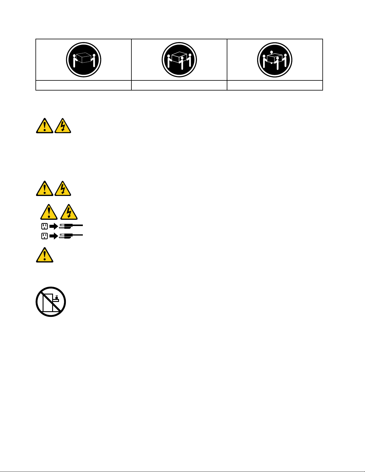
≥18kg(37lbs)≥32kg(70.5lbs)≥55kg(121.2lbs)
1
2
CAUTION:
Usesafepracticeswhenlifting.
CAUTION:
Thepowercontrolbuttononthedeviceandthepowerswitchonthepowersupplydonotturnoff
theelectricalcurrentsuppliedtothedevice.Thedevicealsomighthavemorethanonepower
cord.Toremoveallelectricalcurrentfromthedevice,ensurethatallpowercordsaredisconnected
fromthepowersource.
CAUTION:
Donotplaceanyobjectweighingmorethan82kg(180lbs.)ontopofrack-mounteddevices.
8LenovoC345/C445All-In-OnePCHardwareMaintenanceManual
Page 15

Chapter3.Generalinformation
Thischapterprovidesgeneralinformationthatappliestoallcomputermodelscoveredbythismanual.
Specications
Thissectionliststhephysicalspecicationsforyourcomputer.
Thissectionliststhephysicalspecicationsforyourcomputer.
TypeLenovoC345/C445
Thissectionliststhephysicalspecications.
Environment
Airtemperature:
Operating:10°to35°C
Transit:-20°to55°C
Humidity:
Operating:35%to80%
Transit:20%to90%(40°C)
Altitude:86KPato106KPa
Electricalinput:
Inputvoltage:90V-264V(AC)
Inputfrequency:47Hz-63Hz
©CopyrightLenovo2012
9
Page 16

10LenovoC345/C445All-In-OnePCHardwareMaintenanceManual
Page 17

Chapter4.GeneralCheckout
Attention:Thedrivesinthecomputeryouareservicingmighthavebeenrearrangedorthedrivestartup
sequencemayhavebeenchanged.Beextremelycarefulduringwriteoperationssuchascopying,saving,or
formatting.Dataorprogramscanbeoverwrittenifyouselectanincorrectdrive.
Generalerrormessagesappearifaproblemorconictisfoundbyanapplication,theoperatingsystem,or
both.Foranexplanationofthesemessages,refertotheinformationsuppliedwiththatsoftwarepackage.
Usethefollowingproceduretohelpdeterminethecauseoftheproblem:
1.Power-offthecomputerandallexternaldevices.
2.Checkallcablesandpowercords.
3.Setalldisplaycontrolstothemiddleposition.
4.Power-onallexternaldevices.
5.Power-onthecomputer.
•Lookfordisplayederrorcodes.
•Lookforreadableinstructionsoramainmenuonthedisplay.
Ifyoudidnotreceivethecorrectresponse,proceedtostep6.
Ifyoudidreceivethecorrectresponse,proceedtostep7.
6.Ifoneofthefollowinghappens,followtheinstructiongiven:
•IfthecomputerdisplaysaPOSTerror,goto“POSTerrorcodes” .
•Ifthecomputerhangsandnoerrorisdisplayed,continueatstep7.
7.Iftheteststopsandyoucannotcontinue,replacethelastdevicetested.
©CopyrightLenovo2012
11
Page 18

12LenovoC345/C445All-In-OnePCHardwareMaintenanceManual
Page 19

Chapter5.UsingtheSetupUtility
TheSetupUtilityprogramisusedtoviewandchangethecongurationsettingsofyourcomputer,regardless
ofwhichoperatingsystemyouareusing.However,theoperatingsystemsettingsmightoverrideanysimilar
settingsintheSetupUtilityprogram.
StartingtheLenovoBIOSSetupUtilityprogram
TostarttheLenovoBIOSSetupUtilityprogram,dothefollowing:
1.Ifyourcomputerisalreadyonwhenyoustartthisprocedure,shutdowntheoperatingsystemand
turnoffthecomputer.
2.PressandholdtheF1keythenturnonthecomputer.WhentheLenovoBIOSSetupUtilityprogramis
displayed,releasetheF1key.
Note:IfaPower-OnPasswordoranAdministratorPasswordhasbeenset,theSetupUtilityprogrammenu
willnotbedisplayeduntilyoutypeyourpassword.Formoreinformation,see“Usingpasswords.”
Viewingandchangingsettings
SystemcongurationoptionsarelistedintheLenovoBIOSSetupUtilityprogrammenu.Tovieworchange
settings,see“StartingtheSetupUtilityprogram. ”
YoumustusethekeyboardwhenusingtheLenovoBIOSSetupUtilitymenu.Thekeysusedtoperform
varioustasksaredisplayedonthebottomofeachscreen.
Usingpasswords
YoucanusetheLenovoBIOSSetupUtilityprogramtosetpasswordstopreventunauthorizedpersons
fromgainingaccesstoyourcomputeranddata.See“StartingtheSetupUtilityprogram.”Thefollowing
typesofpasswordsareavailable:
•AdministratorPassword
•Power-OnPassword
Youdonothavetosetanypasswordstouseyourcomputer.However,ifyoudecidetosetpasswords,read
thefollowingsections.
Passwordconsiderations
Apasswordcanbeanycombinationoflettersandnumbersupto16characters(a-zand0-9).Forsecurity
reasons,itisagoodideatouseastrongpasswordthatcannotbeeasilycompromised.Wesuggestthat
passwordsshouldfollowtheserules:
•Forastrongpassword,use7-16charactersandamixoflettersandnumbers.
•Donotuseyournameoryourusername.
•Donotuseacommonwordoracommonname.
•Usesomethingsignicantlydifferentfromyourpreviouspassword.
Attention:AdministratorandPower-Onpasswordsarenotcasesensitive.
©CopyrightLenovo2012
13
Page 20

AdministratorPassword
SettinganAdministratorPassworddetersunauthorizedpersonsfromchangingcongurationsettings.You
mightwanttosetanAdministratorPasswordifyouareresponsibleformaintainingthesettingsofseveral
computers.
AfteryousetanAdministratorPassword,apasswordpromptisdisplayedeverytimeyouaccesstheLenovo
BIOSSetupUtilityprogram.
IfboththeAdministratorandPower-OnPasswordareset,youcantypeeitherpassword.However,youmust
useyourAdministratorPasswordtochangeanycongurationsettings.
Setting,changing,ordeletinganAdministratorpassword
TosetanAdministratorPassword,dothefollowing:
Note:Apasswordcanbeanycombinationoflettersandnumbersupto16characters(a-zand0-9).For
moreinformation,see“Passwordconsiderations”onpage13.
1.StarttheLenovoBIOSSetupUtilityprogram(see“StartingtheLenovoBIOSSetupUtilityprogram”on
page13).
2.FromtheSecuritymenu,selectSetAdministratorPasswordandpresstheEnterkey.
3.Thepassworddialogboxwillbedisplayed.T ypethepasswordthenpresstheEnterkey.
4.Re-typethepasswordtoconrm,thenpresstheEnterkey.Ifyoutypedthepasswordcorrectly,
thepasswordwillbeinstalled.
TochangeanAdministratorPassword,dothefollowing:
1.StarttheLenovoBIOSSetupUtilityprogram(see“StartingtheLenovoBIOSSetupUtilityprogram”on
page13).
2.FromtheSecuritymenu,selectSetAdministratorPasswordandpresstheEnterkey.
3.Thepassworddialogboxwillbedisplayed.TypethecurrentpasswordthenpresstheEnterkey.
4.T ypethenewpassword,thenpresstheEnterkey.Re-typethepasswordtoconrmthenewpassword.
Ifyoutypedthenewpasswordcorrectly,thenewpasswordwillbeinstalled.ASetupNoticedconrming
thatchangeshavebeensavedwillbedisplayed.
TodeleteapreviouslysetAdministratorPassword,dothefollowing:
1.FromtheSecuritymenu,selectSetAdministratorPasswordandpresstheEnterkey.
2.Thepassworddialogboxwillbedisplayed.TypethecurrentpasswordandpresstheEnterkey.
3.T odeleteanAdministratorPassword,leaveeachnewpasswordlineitemblank,thenpresstheEnter
key.ASetupNoticeconrmingthatchangeshavebeensavedwillbedisplayed.
4.ReturntotheLenovoBIOSSetupUtilityprogrammenuandselecttheExitoption.
5.SelectSavechangesandExitfromthemenu.
Power-OnPassword
WhenaPower-OnPasswordisset,youcannotstarttheLenovoBIOSSetupUtilityprogramuntilavalid
passwordistypedfromthekeyboard.
Setting,changing,ordeletingaPower-OnPassword
Note:Apasswordcanbeanycombinationoflettersandnumbersupto16characters(a-zand0-9).
14LenovoC345/C445All-In-OnePCHardwareMaintenanceManual
Page 21

TosetaPower-OnPassword,dothefollowing:
1.StarttheLenovoBIOSSetupUtilityprogram(See”StartingtheLenovoBIOSSetupUtilityprogram”on
page13.)
2.FromtheSecuritymenu,selectSetPower-OnPasswordandpresstheEnterkey.
3.Thepassworddialogboxwillbedisplayed.T ypethepassword,thenpresstheEnterkey.
4.Re-typethepasswordtoconrm.Ifyoutypedthepasswordcorrectly,thepasswordwillbeinstalled.
TochangeaPower-OnPassword,dothefollowing:
1.StarttheLenovoBIOSSetupUtilityprogram(See”StartingtheLenovoBIOSSetupUtilityprogram”on
page13.)
2.FromtheSecuritymenu,selectSetPower-OnPasswordandpresstheEnterkey.
3.Thepassworddialogboxwillbedisplayed.TypethecurrentpasswordthenpresstheEnterkey.
4.T ypethenewpassword,thenpresstheEnterkey.Re-typethepasswordtoconrmthenewpassword.
Ifyoutypedthenewpasswordcorrectly,thenewpasswordwillbeinstalled.ASetupNoticedconrming
thatchangeshavebeensavedwillbedisplayed.
TodeleteapreviouslysetPower-OnPassword,dothefollowing:
1.FromtheSecuritymenu,selectSetPower-OnPasswordandpresstheEnterkey.
2.Thepassworddialogboxwillbedisplayed.TypethecurrentpasswordandpresstheEnterkey.
3.T odeletethePower-OnPassword,leaveeachnewpasswordlineitemblank,thenpressEnter.ASetup
Noticeconrmingthatchangeshavebeensavedwillbedisplayed.
4.ReturntotheLenovoBIOSSetupUtilityprogrammenuandselecttheExitoption.
5.SelectSavechangesandExitfromthemenu.
Enablingordisablingadevice
TheDevicesoptionsisusedtoenableordisableuseraccesstothefollowingdevices:
USBFunctionsSelectwhethertoenableordisableUSB(UniversalSerial
Bus)functions.Ifthefunctionsaredisabled,noUSB
devicescanbeused.
SATAMode
OnboardAudioControllerSelectwhethertoenableordisabletheOnboard
OnboardEthernetControllerorLANBootAgentSelectwhethertoenableordisabletheOnboardEthernet
Toenableordisableadevice,dothefollowing:
1.StarttheSetupUtilityprogram(see“StartingtheSetupUtilityprogram”onpage13).
2.FromtheSetupUtilityprogrammenu,selectDevices.
3.Selectanoptionasfollows:
WhenthisfeatureissettoDisabled,alldevices
connectedtotheSATAconnectors(e.g.harddiskdrives
ortheopticaldiskdrive)aredisabledandcannotbe
accessed.
AudioController.WhenthisfeatureissettoDisabled
alldevicesconnectedtotheaudioconnectors(e.g.
headphonesoramicrophone)aredisabledandcannot
beused.
Controller,orselectwhethertoenableordisableload
onboardPXE(PrebootExecutionEnvironment).
SelectUSBSetup,presstheEnterkey,thenselectUSBFunctions.
Chapter5.UsingtheSetupUtility15
Page 22

SelectA T ADeviceSetup,presstheEnterkey,thenselectSATAMode.
SelectAudioSetup,presstheEnterkey,thenselectOnboardAudioController.
SelectNetworkSetup,presstheEnterkey,thenselectOnboardEthernetSupportorLANBoot
Agent.
4.SelectDisabledorEnabledandpresstheEnterkey.
5.ReturntotheLenovoBIOSSetupUtilityprogrammenuandselecttheExitoption.
6.SelectSavechangesandExitfromthemenu.
Notes:
a.Ifyoudonotwanttosavethesettings,selectDiscardchangesandExitfromthemenu.
b.SelectIDE/AHCIMode:DevicedriversupportisrequiredforACHI.Dependingonhowtheharddisk
imagewasinstalled,changingthissettingmaypreventthesystemfrombooting.
Selectingastartupdevice
IfyourcomputerdoesnotbootfromadevicesuchastheCD/DVD-ROMdrivediskorharddiskasexpected,
followoneoftheproceduresbelow.
Selectingatemporarystartupdevice
Usethisproceduretostartupfromanybootdevice.
Note:NotallCDs,DVDsorharddiskdrivesarebootable.
1.T urnoffyourcomputer.
2.PressandholdtheF12keythenturnonthecomputer.WhentheStartupDeviceMenuappears,
releasetheF12key.
Note:IftheStartupDeviceMenudoesnotdisplayusingthesesteps,repeatedlypressandreleasethe
F12keyratherthankeepingitpressedwhenturningonthecomputer.
3.Use↑and↓arrowstoselectthedesiredstartupdevicefromtheStartupDeviceMenuandpress
theEnterkeytobegin.
Note:SelectingastartupdevicefromtheStartupDeviceMenudoesnotpermanentlychangethe
startupsequence.
Selectingorchangingthestartupdevicesequence
Tovieworpermanentlychangetheconguredstartupdevicesequence,dothefollowing:
1.StarttheLenovoBIOSSetupUtilityprogram(see“StartingtheLenovoBIOSSetupUtilityprogram”on
page13).
2.FromtheLenovoBIOSSetupUtilityprogrammainmenu,selecttheStartupoption.
3.PresstheEnterkey,andselectthedevicesforthePrimaryBootSequence.Readtheinformation
displayedontherightsideofthescreen.
4.Use↑and↓arrowstoselectadevice.Usethe<+>or<->keystomoveadeviceupordown.Usethe
<×>keytoexcludethedevicefromorincludethedeviceinthebootsequence.
5.ReturntotheLenovoBIOSSetupUtilityprogrammenuandselecttheExitoption.
6.SelectSavechangesandExitfromthemenu.
Notes:
16LenovoC345/C445All-In-OnePCHardwareMaintenanceManual
Page 23

a.Ifyoudonotwanttosavethesettings,selectDiscardchangesandExitfromthemenu.
b.Ifyouhavechangedthesesettingsandwanttoreturntothedefaultsettings,selectLoadOptimal
Defaultsfromthemenu.
ExitingtheLenovoBIOSSetupUtilityprogram
Afteryounishviewingorchangingsettings,presstheEsckeytoreturntotheLenovoBIOSSetupUtility
programmainmenu.Y oumighthavetopresstheEsckeyseveraltimes.Dooneofthefollowing:
•Ifyouwanttosavethenewsettings,selectSavechangesandExitfromthemenu.WhentheSave&
resetwindowshows,selecttheYesbutton,andthenpresstheEnterkeytoexittheLenovoBIOS
SetupUtilityprogram.
•Ifyoudonotwanttosavethesettings,selectDiscardchangesandExitfromthemenu.Whenthe
ResetWithoutSavingwindowshows,selecttheYesbutton,andthenpresstheEnterkeytoexitthe
LenovoBIOSSetupUtilityprogram.
Chapter5.UsingtheSetupUtility17
Page 24

18LenovoC345/C445All-In-OnePCHardwareMaintenanceManual
Page 25

Chapter6.Symptom-to-FRUIndex
TheSymptom-to-FRUindexlistserrorsymptomsandpossiblecauses.Themostlikelycauseislistedrst.
AlwaysbeginwithChapter4,“GeneralCheckout, ”onpage11.Thisindexcanalsobeusedtohelpyou
decidewhichFRUstohaveavailablewhenservicingacomputer.Ifyouareunabletocorrecttheproblem
usingthisindex,goto“Undeterminedproblems”onpage20.
Notes:
•Ifyouhavebothanerrormessageandanincorrectaudioresponse,diagnosetheerrormessagerst.
•Ifyoucannotrunthediagnostictestsoryougetadiagnosticerrorcodewhenrunningatestbutdid
receiveaPOSTerrormessage,diagnosethePOSTerrormessagerst.
•Ifyoudidnotreceiveanyerrormessagelookforadescriptionofyourerrorsymptomsintherstpartof
thisindex.
Harddiskdrivebooterror
Aharddiskdrivebooterrorcanbecausedbythefollowing.
Error
Thestartupdriveisnotincludedinthebootsequence
conguration.
Nooperatingsystemisinstalledonthebootdrive.Installanoperatingsystemonthebootdrive.
Thebootsectoronthestartupdriveiscorrupted.
Thedriveisdefective.
FRU/Action
Checkthecongurationandensurethestartupdriveis
inthebootsequence.
Thedrivemustbeformatted.Dothefollowing:
1.Attempttobackupthedataonthefailingharddisk
drive.
2.Usetheoperatingsystemtoformattheharddisk
drive.
Replacetheharddiskdrive.
PowerSupplyProblems
Followtheseproceduresifyoususpectthereisapowersupplyproblem.
Check/VerifyFRU/Action
Checkthatthefollowingareproperlyinstalled:
•PowerCord
•On/OffSwitchconnector
•SystemBoardPowerSupplyconnectors
•Microprocessorconnections
Checkthepowercord.PowerCord
Checkthepower-onswitch.Power-onSwitch
Reseatconnectors
©CopyrightLenovo2012
19
Page 26

POSTerrorcodes
Eachtimeyouturnthecomputeron,itperformsaseriesofteststocheckthatthesystemisoperating
correctlyandthatcertainoptionsareset.ThisseriesoftestsiscalledthePower-OnSelf- T est,orPOST.
POSTdoesthefollowing:
•Checkssomebasicmotherboardoperations
•Checksthatthememoryisworkingcorrectly
•Startsvideooperations
•Veriesthatthebootdriveisworking
POSTErrorMessageDescription/Action
Keyboarderror
RebootandSelectproperBootdeviceorInsertBoot
MediainselectedBootdevice
Cannotinitializethekeyboard.Makesurethekeyboard
isproperlyconnectedtothecomputerandthatnokeys
areheldpressedduringPOST .T opurposelycongure
thecomputerwithoutakeyboard,selectKeyboardless
operationinStartupandsettheoptiontoEnabled.The
BIOSthenignoresthemissingkeyboardduringPOST.
TheBIOSwasunabletondasuitablebootdevice.Make
surethebootdriveisproperlyconnectedtothecomputer.
Makesureyouhavebootablemediainthebootdevice.
Undeterminedproblems
1.Power-offthecomputer.
2.Removeordisconnectthefollowingcomponents(ifconnectedorinstalled)oneatatime.
a.Externaldevices(modem,printer,ormouse)
b.Extendedvideomemory
c.ExternalCache
d.ExternalCacheRAM
e.Harddiskdrive
f.Diskdrive
3.Power-onthecomputertore-testthesystem.
4.Repeatsteps1through3untilyoundthefailingdeviceorcomponent.
Ifalldevicesandcomponentshavebeenremovedandtheproblemcontinues,replacethesystemboard.
20LenovoC345/C445All-In-OnePCHardwareMaintenanceManual
Page 27

Chapter7.Locatingconnectors,controlsandcomponents
1 2
3 7654 8 9
10
Thissectionprovidesillustrationstohelplocatethevariousconnectors,controlsandcomponentsofthe
computer.
Fontview
Thefollowingillustrationshowsthelocationofcontrolsandcomponentsonthefrontofthecomputer.
Attention:Becarefulnottoblockanyairventsonthecomputer.Blockedairventscancauseoverheating.
1.Built-inmicrophone6.Menubutton
2.Built-incamera
3.Harddiskdriveindicator8.Rightdirectionbutton
4.Wi-Fistatusindicator
5.MonitorOn/Offindicator10.Built-inIRreceiver(Onlyfunctionalonmodels
©CopyrightLenovo2012
7.Leftdirectionbutton
9.MonitorOn/Offbutton
equippedwithaIRreceivermodule)
21
Page 28

Leftandrightview
1
2
3
6
5
4
7
8
Thefollowingillustrationshowsthelocationofconnectors,controlsandcomponentsontheleftandright
sideofthecomputer.
1.USBconnector
5.Memorycardreader
2.Headphoneconnector6.Powerbutton
3.Microphoneconnector
7.Opticaldriveejectbutton
4.USBconnector8.Opticaldrive
Attention:Donotinsert3-inchdiscsintotheopticaldrive.
22LenovoC345/C445All-In-OnePCHardwareMaintenanceManual
Page 29

Rearview
1 2 3 7654
8
9
Thefollowingillustrationshowsthelocationofconnectorsandcomponentsontherearofthecomputer.
1.TVtunerconnector(selectedmodelsonly,2connectors
forJapan)
2.TVtunerconnector(selectedmodelsonly,2connectors
forJapan)
3.Powerconnector
4.Ethernetconnector9.Airvents
5.USBconnector
6.USBconnector
7.HDMI-outconnector(selectedmodelsonly)
8.Securitycableslot
Chapter7.Locatingconnectors,controlsandcomponents23
Page 30

Hardwarecomponents
1
2
3
6
7
8
9
10
11
14
18
16
17
15
19
20
21
4
5
12
13
Thefollowingillustrationshowsthecomponentsthatmakeupyourcomputer.
1.Computerstand
12.Wi-Ficard
2.Footcover13.TV- T unercard
3.Middlecover
4.EMIcover15.Heat-sink
5.Motherboard
6.Powerswitchboard17.Harddiskdriveandbay
7.Speakers18.Converterboard
8.RearI/Omodule
9.Chassis20.Opticaldrive
10.LEDpanel
11.Frontbezel
14.Systemfan
16.Camera
19.Frontfunctionboard
21.Opticaldrivebracket
24LenovoC345/C445All-In-OnePCHardwareMaintenanceManual
Page 31

Identifyingpartsonthemotherboard
1 2
3
6
7
8
9
1011121314
15
16
17
18
19
20
21
22
23
4
4
5
Themotherboard(sometimescalledtheplanarorsystemboard)isthemaincircuitboardinyourcomputer.
Itprovidesbasiccomputingfunctionsandsupportsavarietyofdevicesthatarefactory-installedorthat
youcaninstalllater.Thefollowingillustrationshowsthelocationofconnectorsandcomponentsonthe
frontofthemotherboard.
1.HDMI-outconnector12.Battery
2.CPUandsocket
3.Memoryconnector
4.USBconnectors15.DC-inconnector
5.Headphoneconnector
6.Microphoneconnector17.Harddiskdrivepowerconnector
7.Memorycardconnector
8.Speakerconnector19.HarddiskdriveSATAconnector(Balck)
9.Powercontrolconnector(TBD)20.Converterconnector
10.Wi-Ficardconnector
11.TBD
13.TV-T unercardconnector
14.RearI/Omoduleconnector
16.Frontfunctionboard(TBD)
18.OpticaldriveSATAconnector(Red)
21.Cameraconnector
22.Systemfanconnector(22&23TBD,LVDsismissing
inthedrawing)
Chapter7.Locatingconnectors,controlsandcomponents25
Page 32

26LenovoC345/C445All-In-OnePCHardwareMaintenanceManual
Page 33

Chapter8.Replacinghardware
Attention:Donotremovethecomputercoverorattemptanyrepairbeforereadingthe“Importantsafetyinformation”
intheSafetyandWarrantyGuidethatwasincludedwithyourcomputer.T oobtaincopiesoftheSafetyandWarranty
Guide,gototheSupportWebsiteat:http://consumersupport.lenovo.com.
Note:UseonlypartsprovidedbyLenovo.
Generalinformation
Pre-disassemblyinstructions
Beforestartingthedisassemblyprocedure,makesurethatyoudothefollowing:
1.T urnoffthepowertothesystemandallperipherals.
2.Unplugallpowerandsignalcablesfromthecomputer.
3.Placethesystemonaat,stablesurface.
©CopyrightLenovo2012
27
Page 34

Replacingthekeyboardandmouse
Note:YourkeyboardwillbeconnectedtoaUSBconnectorateithersideorattherearofthecomputer.
Toreplacethekeyboard:
Step1.Removeanymedia(disks,CDs,ormemorycards)fromthedrives,shutdownthecomputer,and
turnoffallattacheddevices.
Step2.Unplugallpowercordsfromelectricaloutlets.
Step3.Locatetheconnectorforthekeyboard.Referto“Sideviewofthecomputer”and“Rearviewof
thecomputer”.
Step4.Disconnectthedefectivekeyboardcablefromthecomputerandconnectthenewkeyboardcable
tothesameconnector.
Step5.Themousecanbereplacedusingthesamemethod.
Replacingtheadapter
Attention:Turnoffthecomputerandwait3to5minutestoletitcooldownbeforeremovingthecover.
Step1.Removeanymedia(disks,CDs,ormemorycards)fromthedrives,shutdowntheoperating
system,andturnoffthecomputerandallattacheddevices.
28LenovoC345/C445All-In-OnePCHardwareMaintenanceManual
Page 35

Step2.Disconnecttheadaptercablefromthecomputer1,thenunplugthepowercordfromelectrical
outlet.2
Step3.Connectthenewadapterasshown.12
Chapter8.Replacinghardware29
Page 36

Removingthestandbase
Attention:Turnoffthecomputerandwait3to5minutestoletitcooldownbeforeremovingthecover.
Note:Itmaybehelpfultoplacethecomputerface-downonasoftatsurfaceforthisprocedure.Lenovo
recommendsthatyouuseablanket,towel,orothersoftclothtoprotectthetouchscreenfromscratches
orotherdamage.
Step1.Removeanymedia(disks,CDs,ormemorycards)fromthedrives,shutdowntheoperating
system,andturnoffthecomputerandallattacheddevices.
Step2.Unplugallpowercordsfromelectricaloutlets.
Step3.Disconnectallcablesattachedtothecomputer.Thisincludespowercords,input/output(I/O)
cables,andanyothercablesthatareconnectedtothecomputer.Referto“Leftandrightviews”
and“Rearview”forhelpwithlocatingthevariousconnectors.
Step4.T wistthehandscrewringcounter-clockwiseuntilthebasecomesloosetoreleasethestandbase
fromthestandholder.1
Step5.Slidethestandbaseoutfromtheholderthenputitaside.2
Step6.Referto“Installingthecomputerstand”toreinstallthestandbase.
Removingthefootcover
Attention:Turnoffthecomputerandwait3to5minutestoletitcooldownbeforeremovingthecover.
30LenovoC345/C445All-In-OnePCHardwareMaintenanceManual
Page 37

Note:Itmaybehelpfultoplacethecomputerface-downonasoftatsurfaceforthisprocedure.Lenovo
recommendsthatyouuseablanket,towel,orothersoftclothtoprotectthetouchscreenfromscratches
orotherdamage.
Step1.Removeanymedia(disks,CDs,ormemorycards)fromthedrives,shutdowntheoperating
system,andturnoffthecomputerandallattacheddevices.
Step2.Unplugallpowercordsfromelectricaloutlets.
Step3.Disconnectallcablesattachedtothecomputer.Thisincludespowercords,input/output(I/O)
cables,andanyothercablesthatareconnectedtothecomputer.Referto“Leftandrightviews”
and“Rearview”forhelpwithlocatingthevariousconnectors.
Step4.Removethefootbase.Referto“Removingthefootbase” .
Step5.Liftupthestandholderthenslideoutthefootcoverasshown.
Step6.T oreattachthefootcover:
a.Liftupthestandholder.
b.Lineupthefootcoverwithmountingholesonthebackofthecomputer,thenslideitbackinto
position.
Replacingamemorymodule
Attention:Turnoffthecomputerandwait3to5minutestoletitcooldownbeforeremovingthecover.
Chapter8.Replacinghardware31
Page 38

Note:Itmaybehelpfultoplacethecomputerface-downonasoftatsurfaceforthisprocedure.Lenovo
recommendsthatyouuseablanket,towel,orothersoftclothtoprotectthetouchscreenfromscratches
orotherdamage.
Step1.Removeanymedia(disks,CDs,ormemorycards)fromthedrives,shutdowntheoperating
system,andturnoffthecomputerandallattacheddevices.
Step2.Unplugallpowercordsfromelectricaloutlets.
Step3.Disconnectallcablesattachedtothecomputer.Thisincludespowercords,input/output(I/O)
cables,andanyothercablesthatareconnectedtothecomputer.Referto“Leftandrightviews”
and“Rearview”forhelpwithlocatingthevariousconnectors.
Step4.Removethestandbase.Referto“Removingthestandbase” .
Step5.Removethefootcover.Referto“Removingthefootcover”.
Step6.Pushoutthelatchesonbothsidesofthememorysockettoreleasethememorymodule1and
gentlypullthememorymoduleupwardtoremoveitfromitssocket.2Allofthememorymodules
canberemovedusingthesameprocedure.
Step7.T oinstallamemorymodule:
a.Alignthenewmemorymodulewiththememorysocket,theninsertitandpushdownonthe
topedge.Makesurethelatcheslockthememorymoduleinplace.
Step8.Reattachthefootcoverandstandbase.
32LenovoC345/C445All-In-OnePCHardwareMaintenanceManual
Page 39

Replacingtheharddiskdrive
1
1
Attention:Turnoffthecomputerandwait3to5minutestoletitcooldownbeforeremovingthecover.
Note:Itmaybehelpfultoplacethecomputerface-downonasoftatsurfaceforthisprocedure.Lenovo
recommendsthatyouuseablanket,towel,orothersoftclothtoprotectthetouchscreenfromscratches
orotherdamage.
Step1.Removeanymedia(disks,CDs,ormemorycards)fromthedrives,shutdowntheoperating
system,andturnoffthecomputerandallattacheddevices.
Step2.Unplugallpowercordsfromelectricaloutlets.
Step3.Disconnectallcablesattachedtothecomputer.Thisincludespowercords,input/output(I/O)
cables,andanyothercablesthatareconnectedtothecomputer.Referto“Leftandrightviews”
and“Rearview”forhelpwithlocatingthevariousconnectors.
Step4.Removethestandbase.Referto“Removingthestandbase” .
Step5.Removethefootcover.Referto“Removingthefootcover”.
Step6.Pushtheharddiskdrivebracket1,thenslidetheharddiskdriveandbracketoutofthechassisas
shown.2
Chapter8.Replacinghardware33
Page 40

Step7.Pushthelockpinsoutwardtoreleasetheharddiskdrivefromthebracket.
Step8.T oinstallthenewharddiskdrive:
a.Lineupthenewharddiskdrivewiththebracketandsecureitwiththepins.
b.Slidetheharddiskdriveandbracketbackintoposition.
Step9.Reattachthefootcoverandstandbase.
Replacingtheopticaldrive
Attention:Turnoffthecomputerandwait3to5minutestoletitcooldownbeforeremovingthecover.
Note:Itmaybehelpfultoplacethecomputerface-downonasoftatsurfaceforthisprocedure.Lenovo
recommendsthatyouuseablanket,towel,orothersoftclothtoprotectthetouchscreenfromscratches
orotherdamage.
Step1.Removeanymedia(disks,CDs,ormemorycards)fromthedrives,shutdowntheoperating
system,andturnoffthecomputerandallattacheddevices.
Step2.Unplugallpowercordsfromelectricaloutlets.
Step3.Disconnectallcablesattachedtothecomputer.Thisincludespowercords,input/output(I/O)
cables,andanyothercablesthatareconnectedtothecomputer.Referto“Leftandrightviews”
and“Rearview”forhelpwithlocatingthevariousconnectors.
Step4.Removethestandbase.Referto“Removingthestandbase” .
Step5.Removethefootcover.Referto“Removingthefootcover”.
34LenovoC345/C445All-In-OnePCHardwareMaintenanceManual
Page 41

Step6.Pushtheopticaldrivepindownwardtopushouttheopticaldriveasshown.12
Step7.Pushasmallironstick(paperclip)intothesmallholeontheopticaldrivecoversothatthedisk
springsoutasshown.
Step8.Removethe2screwsthatsecuretheopticaldrivetothemetalbracket.1
Step9.Useasmallatheadscrewdrivertopressandpushoutthepinsthatsecurethecovertothe
disk.23
Chapter8.Replacinghardware35
Page 42

Step10.Separatethecoverfromthedefectiveopticaldrive.
Step11.T oinstallthenewopticaldrive:
a.Alignthenewopticaldrivewiththecover,andthenpushthecoverbackintoposition.
b.Screwthemetalbracketbackontothenewopticaldrive.
c.Slidethenewopticaldriveintothedrivebay.
Step12.Reattachthefootcoverandstandbase.
Removingthestandholder
Note:Turnoffthecomputerandwait3to5minutestoletitcooldownbeforeremovingthecover.
Note:Itmaybehelpfultoplacethecomputerface-downonasoftatsurfaceforthisprocedure.Lenovo
recommendsthatyouuseablanket,towel,orothersoftclothtoprotectthecomputerscreenfromscratches
orotherdamage.
Toremovethestandholder:
Step1.Removeanymedia(disks,CDs,DVDs,ormemorycards)fromthedrives,shutdowntheoperating
system,andturnoffthecomputerandallattacheddevices.
Step2.Unplugallpowercordsfromelectricaloutlets.
Step3.Disconnectallcablesattachedtothecomputer.Thisincludespowercords,input/output(I/O)
cables,andanyothercablesthatareconnectedtothecomputer.Referto“Leftandrightview”
and“Rearview”forhelpwithlocatingthevariousconnectors.
Step4.Removethestandbase.Referto“Removingthestandbase” .
Step5.Removethefootcover.Referto“Removingthefootcover”.
Step6.Removethefourscrewsthatsecurethestandholdertothechassis,thenliftupthestandholderto
removeit.
36LenovoC345/C445All-In-OnePCHardwareMaintenanceManual
Page 43

Step7.T oreattachthestandholder:
a.Aligntheholesonthestandholderwithmountingholesonthechassis,placethestand
holderbackintoposition.
b.Securethestandholdertothechassiswiththefourscrews.
Step8.Lineupthefootcoverwithmountingholesonthebackofthecomputer,thenslideitbackinto
position.
Step9.Reattachthestandbase.
Removingthemiddlecover
Note:Turnoffthecomputerandwait3to5minutestoletitcooldownbeforeremovingthecover.
Note:Itmaybehelpfultoplacethecomputerface-downonasoftatsurfaceforthisprocedure.Lenovo
recommendsthatyouuseablanket,towel,orothersoftclothtoprotectthecomputerscreenfromscratches
orotherdamage.
Toremovethemiddlecover:
Step1.Removeanymedia(disks,CDs,DVDs,ormemorycards)fromthedrives,shutdowntheoperating
system,andturnoffthecomputerandallattacheddevices.
Step2.Unplugallpowercordsfromelectricaloutlets.
Step3.Disconnectallcablesattachedtothecomputer.Thisincludespowercords,input/output(I/O)
cables,andanyothercablesthatareconnectedtothecomputer.Referto“Leftandrightview”
and“Rearview”forhelpwithlocatingthevariousconnectors.
Step4.Removethestandbase.Referto“Removingthestandbase” .
Step5.Removethefootcover.Referto“Removingthefootcover”.
Step6.Removetheopticaldrive.Referto“Replacingtheopticaldrive” .
Step7.Removethestandholder.Referto“Removingthestandholder” .
Step8.Removethevescrewsthatsecurethemiddlecovertothechassis,thenliftupthemiddlecover
fromtheleftside(opticaldriveside)toremovethemiddlecover.
Chapter8.Replacinghardware37
Page 44

Step9.T oreattachthemiddlecover:
a.Lineupthemiddlecoverwithchassis,thenplacethemiddlecoverback.
b.Securethemiddlecovertothechassiswiththevescrews.
Step10.Reattachthestandholder,opticaldrive,footcoverandstandbase.
Replacingtheconverterboard
Note:Turnoffthecomputerandwait3to5minutestoletitcooldownbeforeremovingthecover.
Note:Itmaybehelpfultoplacethecomputerface-downonasoftatsurfaceforthisprocedure.Lenovo
recommendsthatyouuseablanket,towel,orothersoftclothtoprotectthecomputerscreenfromscratches
orotherdamage.
Toreplacetheconverterboard:
Step1.Removeanymedia(disks,CDs,DVDs,ormemorycards)fromthedrives,shutdowntheoperating
system,andturnoffthecomputerandallattacheddevices.
Step2.Unplugallpowercordsfromelectricaloutlets.
Step3.Disconnectallcablesattachedtothecomputer.Thisincludespowercords,input/output(I/O)
cables,andanyothercablesthatareconnectedtothecomputer.Referto“Leftandrightview”
and“Rearview”forhelpwithlocatingthevariousconnectors.
Step4.Removethestandbase.Referto“Removingthestandbase” .
Step5.Removethefootcover.Referto“Removingthefootcover”.
Step6.Removetheopticaldrive.Referto“Replacingtheopticaldrive” .
Step7.Removethestandholder.Referto“Removingthestandholder” .
Step8.Removethemiddlecover.Referto“Removingthemiddlecover”.
38LenovoC345/C445All-In-OnePCHardwareMaintenanceManual
Page 45

Step9.Disconnectthetwocablesfromtheconverter,andthenremovethetwoscrewsthatsecurethe
converterboardtothechassis.
Step10.Liftuptheconverterboardtoremoveit.
Step11.T oinstallthenewconverterboard:
a.Lineuptheholesonthenewconverterboardwiththemountingholesonthechassisand
secureitwiththetwoscrews.
b.Connectthetwocablestothenewconverterboard.
Step12.Reattachthemiddlecover,opticaldrive,standholder,footcoverandstandbase.
Replacingthecamera
Note:Turnoffthecomputerandwait3to5minutestoletitcooldownbeforeremovingthecover.
Note:Itmaybehelpfultoplacethecomputerface-downonasoftatsurfaceforthisprocedure.Lenovo
recommendsthatyouuseablanket,towel,orothersoftclothtoprotectthecomputerscreenfromscratches
orotherdamage.
Toreplacethecamera:
Step1.Removeanymedia(disks,CDs,DVDs,ormemorycards)fromthedrives,shutdowntheoperating
system,andturnoffthecomputerandallattacheddevices.
Step2.Unplugallpowercordsfromelectricaloutlets.
Step3.Disconnectallcablesattachedtothecomputer.Thisincludespowercords,input/output(I/O)
cables,andanyothercablesthatareconnectedtothecomputer.Referto“Leftandrightview”
and“Rearview”forhelpwithlocatingthevariousconnectors.
Step4.Removethestandbase.Referto“Removingthestandbase” .
Step5.Removethefootcover.Referto“Removingthefootcover”.
Step6.Removetheopticaldrive.Referto“Replacingtheopticaldrive” .
Step7.Removethestandholder.Referto“Removingthestandholder” .
Step8.Removethemiddlecover.Referto“Removingthemiddlecover”.
Chapter8.Replacinghardware39
Page 46

Step9.Removethetwoscrewsthatsecurecameratothefrontbezel.1
Step10.Liftupthecamera2anddisconnectthedatacablefromthecamera.3
Step11.T oinstallthenewcamera:
a.Connectthedatacabletothenewcamera.
b.Lineuptheholesinthenewcamerawiththemountingholesonthefrontbezelandsecureit
withthetwoscrews.
Step12.Reattachthemiddlecover,opticaldrive,standholder,footcoverandstandbase.
RemovingtheEMIcover
Note:Turnoffthecomputerandwait3to5minutestoletitcooldownbeforeremovingthecover.
Note:Itmaybehelpfultoplacethecomputerface-downonasoftatsurfaceforthisprocedure.Lenovo
recommendsthatyouuseablanket,towel,orothersoftclothtoprotectthecomputerscreenfromscratches
orotherdamage.
ToreplacetheEMIcover
Step1.Removeanymedia(disks,CDs,DVDs,ormemorycards)fromthedrives,shutdowntheoperating
system,andturnoffthecomputerandallattacheddevices.
Step2.Unplugallpowercordsfromelectricaloutlets.
40LenovoC345/C445All-In-OnePCHardwareMaintenanceManual
Page 47

Step3.Disconnectallcablesattachedtothecomputer.Thisincludespowercords,input/output(I/O)
cables,andanyothercablesthatareconnectedtothecomputer.Referto“Leftandrightview”
and“Rearview”forhelpwithlocatingthevariousconnectors.
Step4.Removethestandbase.Referto“Removingthestandbase” .
Step5.Removethefootcover.Referto“Removingthefootcover”.
Step6.Removetheopticaldrive.Referto“Replacingtheopticaldrive” .
Step7.Removethestandholder.Referto“Removingthestandholder” .
Step8.Removethemiddlecover.Referto“Removingthemiddlecover”.
Step9.RemovethetwoscrewsthatsecuretheEMIcovertothechassis1,andthenliftitup.2
Step10.T oreattachtheEMIcover:
a.LineuptheholesontheEMIcoverwithmountingholesonthechassis,thenplaceEMIcover
backintoposition.
b.SecuretheEMIcovertothechassiswithtwoscrews.
Step11.Reattachthemiddlecover,opticaldrive,standholder,footcoverandstandbase.
ReplacingtherearI/Omodule
Note:Turnoffthecomputerandwait3to5minutestoletitcooldownbeforeremovingthecover.
Note:Itmaybehelpfultoplacethecomputerface-downonasoftatsurfaceforthisprocedure.Lenovo
recommendsthatyouuseablanket,towel,orothersoftclothtoprotectthecomputerscreenfromscratches
orotherdamage.
ToreplacetherearI/Omodule
Step1.Removeanymedia(disks,CDs,DVDs,ormemorycards)fromthedrives,shutdowntheoperating
system,andturnoffthecomputerandallattacheddevices.
Chapter8.Replacinghardware41
Page 48

Step2.Unplugallpowercordsfromelectricaloutlets.
Step3.Disconnectallcablesattachedtothecomputer.Thisincludespowercords,input/output(I/O)
cables,andanyothercablesthatareconnectedtothecomputer.Referto“Leftandrightview”
and“Rearview”forhelpwithlocatingthevariousconnectors.
Step4.Removethestandbase.Referto“Removingthestandbase” .
Step5.Removethefootcover.Referto“Removingthefootcover”.
Step6.Removetheopticaldrive.Referto“Replacingtheopticaldrive” .
Step7.Removethestandholder.Referto“Removingthestandholder” .
Step8.Removethemiddlecover.Referto“Removingthemiddlecover”.
Step9.RemovetheEMIcover.Referto“RemovingtheEMIcover”.
Step10.RemovethetwoscrewsthatsecuretherearI/Omoduletothemotherboard1andliftitup
gently.2
Step11.DisconnectthepowercablefromthemotherboardandtheTVantennacable(s)fromtheTVtuner
card.
42LenovoC345/C445All-In-OnePCHardwareMaintenanceManual
Page 49

Step12.RemovethetwoscrewsthatsecurerearI/Omoduletothebracket1,loosetherearI/Omodule,
thenslideitout.2
Step13.T oinstallthenewrearI/Omodule:
a.LineupthenewI/Omodulewithbracket,theninserttherearI/Omoduleintoposition.
b.SecuretherearI/Omoduletothebracketwiththetwoscrews.
c.ConnectthepowercabletothemotherboardandtheTVantennacable(s)totheTVtunercard.
Step14.ReattachtheEMIcover,middlecover,opticaldrive,standholder,footcoverandstandbase.
Replacingthespeakersystem
Note:Turnoffthecomputerandwait3to5minutestoletitcooldownbeforeremovingthecover.
Note:Itmaybehelpfultoplacethecomputerface-downonasoftatsurfaceforthisprocedure.Lenovo
recommendsthatyouuseablanket,towel,orothersoftclothtoprotectthecomputerscreenfromscratches
orotherdamage.
Toreplacethespeakersystem:
Step1.Removeanymedia(disks,CDs,DVDs,ormemorycards)fromthedrives,shutdowntheoperating
system,andturnoffthecomputerandallattacheddevices.
Step2.Unplugallpowercordsfromelectricaloutlets.
Step3.Disconnectallcablesattachedtothecomputer.Thisincludespowercords,input/output(I/O)
cables,andanyothercablesthatareconnectedtothecomputer.Referto“Leftandrightview”
and“Rearview”forhelpwithlocatingthevariousconnectors.
Step4.Removethestandbase.Referto“Removingthestandbase” .
Step5.Removethefootcover.Referto“Removingthefootcover”.
Step6.Removetheopticaldrive.Referto“Replacingtheopticaldrive” .
Chapter8.Replacinghardware43
Page 50

Step7.Removethestandholder.Referto“Removingthestandholder” .
Step8.Removethemiddlecover.Referto“Removingthemiddlecover”.
Step9.RemovetheEMIcover.Referto“RemovingtheEMIcover”.
Step10.Disconnectthespeakercablesfromtheconnectoronthemotherboard.
Step11.Removethefourscrewsthatsecurethespeakersystemtothechassis,thenliftupthespeaker
systemtoremoveit.
Step12.T oinstallthenewspeakersystem:
a.Placethenewspeakersystemintoposition,thensecureitwithfourscrews.
b.Connectthenewspeakercablestotheconnectoronthemotherboard.
Step13.ReattachtheEMIcover,middlecover,opticaldrive,standholder,footcoverandstandbase.
Replacingthesystemfan
Note:Turnoffthecomputerandwait3to5minutestoletitcooldownbeforeremovingthecover.
Note:Itmaybehelpfultoplacethecomputerface-downonasoftatsurfaceforthisprocedure.Lenovo
recommendsthatyouuseablanket,towel,orothersoftclothtoprotectthecomputerscreenfromscratches
orotherdamage.
Toreplacethesystemfan
Step1.Removeanymedia(disks,CDs,DVDs,ormemorycards)fromthedrives,shutdowntheoperating
system,andturnoffthecomputerandallattacheddevices.
Step2.Unplugallpowercordsfromelectricaloutlets.
Step3.Disconnectallcablesattachedtothecomputer.Thisincludespowercords,input/output(I/O)
cables,andanyothercablesthatareconnectedtothecomputer.Referto“Leftandrightview”
and“Rearview”forhelpwithlocatingthevariousconnectors.
Step4.Removethestandbase.Referto“Removingthestandbase” .
Step5.Removethefootcover.Referto“Removingthefootcover”.
Step6.Removetheopticaldrive.Referto“Replacingtheopticaldrive” .
Step7.Removethestandholder.Referto“Removingthestandholder” .
Step8.Removethemiddlecover.Referto“Removingthemiddlecover”.
44LenovoC345/C445All-In-OnePCHardwareMaintenanceManual
Page 51

Step9.RemovetheEMIcover.Referto“RemovingtheEMIcover”.
Step10.Removethesealingtapebetweenthesystemfanandheat-sink.
Step11.Removethetwoscrewsthatsecurethesystemfantothechassis.
Step12.Disconnectthepowercablefromthemotherboard.
Step13.Liftupthesystemfantoremoveit.
Step14.T oinstallthenewsystemfan:
a.Placethenewsystemfanintoposition,andthensecureittothechassis.
b.Connectthesystemfanpowercabletotheconnectoronthemotherboard.
c.Usethesealingtapetosealthegapin-betweenthesystemfanandheat-sink.
Step15.ReattachtheEMIcover,middlecover,opticaldrive,standholder,footcoverandstandbase.
Replacingtheheat-sink
Note:Turnoffthecomputerandwait3to5minutestoletitcooldownbeforeremovingthecover.
Note:Itmaybehelpfultoplacethecomputerface-downonasoftatsurfaceforthisprocedure.Lenovo
recommendsthatyouuseablanket,towel,orothersoftclothtoprotectthecomputerscreenfromscratches
orotherdamage.
Toreplacetheheat-sink:
Step1.Removeanymedia(disks,CDs,DVDs,ormemorycards)fromthedrives,shutdowntheoperating
system,andturnoffthecomputerandallattacheddevices.
Step2.Unplugallpowercordsfromelectricaloutlets.
Step3.Disconnectallcablesattachedtothecomputer.Thisincludespowercords,input/output(I/O)
cables,andanyothercablesthatareconnectedtothecomputer.Referto“Leftandrightview”
and“Rearview”forhelpwithlocatingthevariousconnectors.
Step4.Removethestandbase.Referto“Removingthestandbase” .
Step5.Removethefootcover.Referto“Removingthefootcover”.
Step6.Removetheopticaldrive.Referto“Replacingtheopticaldrive” .
Step7.Removethestandholder.Referto“Removingthestandholder” .
Step8.Removethemiddlecover.Referto“Removingthemiddlecover”.
Chapter8.Replacinghardware45
Page 52

Step9.RemovetheEMIcover.Referto“RemovingtheEMIcover”.
Step10.Removethesealingtapebetweenthesystemfanandheat-sink.
Step11.Removethevescrewsthatsecuretheheat-sinktothemotherboardandchassis.
Step12.Removetheheat-sinkbyliftingitup.
Attention:Placetheheat-sinkupsidedownonaatsurfacetopreventthermalgreasefromcontaminating
othercomponents.
Attention:UseanalcoholpadtowipethethermalgreaseofftheCPU.
Step13.T oinstallthenewheat-sink:
a.Lineupthenewheat-sinkwithmountingholesonthemotherboard,thenplaceitintoposition.
b.Followthenumbersprintedonthenewheat-sinktosecureitinorderusingthefourscrews.
c.Usethesealingtapetosealthegapin-betweenthesystemfanandheat-sink.
Step14.ReattachtheEMIcover,middlecover,opticaldrive,standholder,footcoverandstandbase.
ReplacingtheTVtunercard
Note:Turnoffthecomputerandwait3to5minutestoletitcooldownbeforeremovingthecover.
Note:Itmaybehelpfultoplacethecomputerface-downonasoftatsurfaceforthisprocedure.Lenovo
recommendsthatyouuseablanket,towel,orothersoftclothtoprotectthecomputerscreenfromscratches
orotherdamage.
ToreplacetheTVtunercard
Step1.Removeanymedia(disks,CDs,DVDs,ormemorycards)fromthedrives,shutdowntheoperating
system,andturnoffthecomputerandallattacheddevices.
Step2.Unplugallpowercordsfromelectricaloutlets.
Step3.Disconnectallcablesattachedtothecomputer.Thisincludespowercords,input/output(I/O)
cables,andanyothercablesthatareconnectedtothecomputer.Referto“Leftandrightview”
and“Rearview”forhelpwithlocatingthevariousconnectors.
Step4.Removethestandbase.Referto“Removingthestandbase” .
Step5.Removethefootcover.Referto“Removingthefootcover”.
Step6.Removetheopticaldrive.Referto“Replacingtheopticaldrive” .
46LenovoC345/C445All-In-OnePCHardwareMaintenanceManual
Page 53

Step7.Removethestandholder.Referto“Removingthestandholder” .
Step8.Removethemiddlecover.Referto“Removingthemiddlecover”.
Step9.RemovetheEMIcover.Referto“RemovingtheEMIcover”.
Step10.DisconnecttheantennacablefromtheTV- T unercard.
Step11.RemovethescrewthatsecurestheTV- T unercardtothemotherboard.
Step12.PulltheTV-Tunercardupwardtoremoveitfromthecardportonthemotherboard.
Step13.T oinstallthenewTV-Tunercard:
a.InsertthenotchedendoftheTV-T unercardintothecardportonthemotherboard.
b.SecurenewtheTV-Tunercardtothemotherboardwiththescrew.
c.ConnecttheantennacabletothenewTV- Tunercard.
Step14.ReattachtheEMIcover,middlecover,opticaldrive,standholder,footcoverandstandbase.
ReplacingtheWLANcard
Note:Turnoffthecomputerandwait3to5minutestoletitcooldownbeforeremovingthecover.
Note:Itmaybehelpfultoplacethecomputerface-downonasoftatsurfaceforthisprocedure.Lenovo
recommendsthatyouuseablanket,towel,orothersoftclothtoprotectthecomputerscreenfromscratches
orotherdamage.
ToreplacetheWLANcard:
Step1.Removeanymedia(disks,CDs,DVDs,ormemorycards)fromthedrives,shutdowntheoperating
system,andturnoffthecomputerandallattacheddevices.
Step2.Unplugallpowercordsfromelectricaloutlets.
Step3.Disconnectallcablesattachedtothecomputer.Thisincludespowercords,input/output(I/O)
cables,andanyothercablesthatareconnectedtothecomputer.Referto“Leftandrightview”
and“Rearview”forhelpwithlocatingthevariousconnectors.
Step4.Removethestandbase.Referto“Removingthestandbase” .
Step5.Removethefootcover.Referto“Removingthefootcover”.
Step6.Removetheopticaldrive.Referto“Replacingtheopticaldrive” .
Step7.Removethestandholder.Referto“Removingthestandholder” .
Step8.Removethemiddlecover.Referto“Removingthemiddlecover”.
Chapter8.Replacinghardware47
Page 54

Step9.RemovetheEMIcover.Referto“RemovingtheEMIcover”.
Step10.DisconnecttheantennacablesfromtheWLANcard.
Step11.RemovethescrewthatsecurestheWLANcardtothemotherboard.
Step12.LiftuptheWLANcardtoremoveitfromthesocket.
Step13.T oinstallthenewWLANcard:
a.InsertthenotchedendoftheWLANcardintothecardportonthemotherboard.
b.SecurenewtheWLANcardtothemotherboardwiththescrew.
c.ConnecttheantennacablestothenewWLANcard.
Step14.ReattachtheEMIcover,middlecover,opticaldrive,standholder,footcoverandstandbase.
Replacingthefrontcontrolboard
Note:Turnoffthecomputerandwait3to5minutestoletitcooldownbeforeremovingthecover.
Note:Itmaybehelpfultoplacethecomputerface-downonasoftatsurfaceforthisprocedure.Lenovo
recommendsthatyouuseablanket,towel,orothersoftclothtoprotectthecomputerscreenfromscratches
orotherdamage.
Toreplacethefrontcontrolboard:
Step1.Removeanymedia(disks,CDs,DVDs,ormemorycards)fromthedrives,shutdowntheoperating
system,andturnoffthecomputerandallattacheddevices.
Step2.Unplugallpowercordsfromelectricaloutlets.
Step3.Disconnectallcablesattachedtothecomputer.Thisincludespowercords,input/output(I/O)
cables,andanyothercablesthatareconnectedtothecomputer.Referto“Leftandrightview”
and“Rearview”forhelpwithlocatingthevariousconnectors.
Step4.Removethestandbase.Referto“Removingthestandbase” .
Step5.Removethefootcover.Referto“Removingthefootcover”.
Step6.Removetheopticaldrive.Referto“Replacingtheopticaldrive” .
Step7.Removethestandholder.Referto“Removingthestandholder” .
Step8.Removethemiddlecover.Referto“Removingthemiddlecover”.
Step9.RemovetheEMIcover.Referto“RemovingtheEMIcover”.
Step10.Removethespeakersystem.Referto“Replacingthespeakersystem” .
Step11.Pushthepinthatlocksthefrontcontrolboard,thenslideitout.
48LenovoC345/C445All-In-OnePCHardwareMaintenanceManual
Page 55

Step12.Disconnectthedatacablefromthefrontcontrolboard,thenliftupthefrontcontrolboard.
Step13.T oinstallthenewfrontcontrolboard:
a.Connectthedatacabletothenewfrontcontrolboard.
b.Lineupthenewfrontcontrolboardwiththefrontbezel,thenplaceitintoposition.
Step14.Reattachthespeakersystem,EMIcover,middlecover,opticaldrive,standholder,footcover
andstandbase.
Replacingthepowerswitchboard
Note:Turnoffthecomputerandwait3to5minutestoletitcooldownbeforeremovingthecover.
Note:Itmaybehelpfultoplacethecomputerface-downonasoftatsurfaceforthisprocedure.Lenovo
recommendsthatyouuseablanket,towel,orothersoftclothtoprotectthecomputerscreenfromscratches
orotherdamage.
Toreplacethepowerswitchboard
Step1.Removeanymedia(disks,CDs,DVDs,ormemorycards)fromthedrives,shutdowntheoperating
system,andturnoffthecomputerandallattacheddevices.
Step2.Unplugallpowercordsfromelectricaloutlets.
Step3.Disconnectallcablesattachedtothecomputer.Thisincludespowercords,input/output(I/O)
cables,andanyothercablesthatareconnectedtothecomputer.Referto“Leftandrightview”
and“Rearview”forhelpwithlocatingthevariousconnectors.
Step4.Removethestandbase.Referto“Removingthestandbase” .
Step5.Removethefootcover.Referto“Removingthefootcover”.
Step6.Removetheopticaldrive.Referto“Replacingtheopticaldrive” .
Step7.Removethestandholder.Referto“Removingthestandholder” .
Step8.Removethemiddlecover.Referto“Removingthemiddlecover”.
Step9.RemovetheEMIcover.Referto“RemovingtheEMIcover”.
Chapter8.Replacinghardware49
Page 56

Step10.Gentlypushthepinthatlocksthepowerswitchboardtoreleaseit,thenslidethepowerswitch
boardout.
Step11.Disconnectthedatacablefromthepowerswitchboard.
Step12.T oinstallthepowerswitchboard:
a.LineuptheholeonthenewpowerswitchboardwiththemountingholeontheLEDpanel(待
确认),thenplaceitintoposition.
b.Connectthepowercabletothenewpowerswitchboard.
Step13.ReattachtheEMIcover,middlecover,opticaldrive,standholder,footcoverandstandbase.
Replacingthemotherboard
Note:Turnoffthecomputerandwait3to5minutestoletitcooldownbeforeremovingthecover.
Note:Itmaybehelpfultoplacethecomputerface-downonasoftatsurfaceforthisprocedure.Lenovo
recommendsthatyouuseablanket,towel,orothersoftclothtoprotectthecomputerscreenfromscratches
orotherdamage.
Toreplacethemotherboard:
Step1.Removeanymedia(disks,CDs,DVDs,ormemorycards)fromthedrives,shutdowntheoperating
system,andturnoffthecomputerandallattacheddevices.
Step2.Unplugallpowercordsfromelectricaloutlets.
Step3.Disconnectallcablesattachedtothecomputer.Thisincludespowercords,input/output(I/O)
cables,andanyothercablesthatareconnectedtothecomputer.Referto“Leftandrightview”
and“Rearview”forhelpwithlocatingthevariousconnectors.
Step4.Removethestandbase.Referto“Removingthestandbase” .
Step5.Removethefootcover.Referto“Removingthefootcover”.
Step6.Removethememorymodules.Referto“Replacingamemorymodule” .
Step7.Removetheopticaldrive.Referto“Replacingtheopticaldrive” .
Step8.Removethestandholder.Referto“Removingthestandholder” .
50LenovoC345/C445All-In-OnePCHardwareMaintenanceManual
Page 57

Step9.Removethemiddlecover.Referto“Removingthemiddlecover”.
Step10.RemovetheEMIcover.Referto“RemovingtheEMIcover”.
Step11.RemovetherearI/Omodule.Referto“ReplacingtherearI/Omodule” .
Step12.Removetheheat-sink.Referto“Replacingtheheat-sink” .
Step13.RemovetheCPU.Referto“ReplacingtheCPU” .(FormodelsC340andC440only.)
Step14.RemovetheTV- T unercard.Referto“ReplacingtheTVtunercard”.
Step15.RemovetheWLANcard.Referto“ReplacingtheWLANcard” .
Step16.Unplugthefollowingcablesfromconnectorsonthemotherboard:
•Powerswitchboardcable
•Speakersystemcable
•Frontcontrolboardcable
•Convertercable
•Cameracable
•Systemfanpowercable
•Harddiskdrivepowercable
•HarddiskdriveSATAcable(Black)
•OpticaldriveSATAcable(Red)
•LEDpaneldatacable
Step17.Removethevescrewsthatsecurethemotherboardtothechassisandliftthemotherboard
uptoremoveit.
Step18.T oinstallthenewmotherboard:
a.Lineuptheholesonthenewmotherboardwiththemountingholeschassisandplacethenew
motherboardintoposition.
b.Usethescrewstosecurethenewmotherboardtothechassis.
c.Connectallthecablestothenewmotherboard.
Step19.Installthefollowingpartstothenewmotherboard:
•WLANcard
•TV-Tunercard
Chapter8.Replacinghardware51
Page 58

•CPU
•Heat-sink
•RearI/Omodule
•Memorymodule
Step20.ReattachtheEMIcover,middlecover,opticaldrive,standholder,footcoverandstandbase.
ReplacingtheLEDpanel
Note:Turnoffthecomputerandwait3to5minutestoletitcooldownbeforeremovingthecover.
Note:Itmaybehelpfultoplacethecomputerface-downonasoftatsurfaceforthisprocedure.Lenovo
recommendsthatyouuseablanket,towel,orothersoftclothtoprotectthecomputerscreenfromscratches
orotherdamage.
ToreplacetheLEDpanel:
Step1.Removeanymedia(disks,CDs,DVDs,ormemorycards)fromthedrives,shutdowntheoperating
system,andturnoffthecomputerandallattacheddevices.
Step2.Unplugallpowercordsfromelectricaloutlets.
Step3.Disconnectallcablesattachedtothecomputer.Thisincludespowercords,input/output(I/O)
cables,andanyothercablesthatareconnectedtothecomputer.Referto“Leftandrightview”
and“Rearview”forhelpwithlocatingthevariousconnectors.
Step4.Removethestandbase.Referto“Removingthestandbase” .
Step5.Removethefootcover.Referto“Removingthefootcover”.
Step6.Removethememorymodules.Referto“Replacingamemorymodule” .
Step7.Removetheopticaldrive.Referto“Replacingtheopticaldrive” .
Step8.Removethestandholder.Referto“Removingthestandholder” .
Step9.Removethemiddlecover.Referto“Removingthemiddlecover”.
Step10.RemovetheEMIcover.Referto“RemovingtheEMIcover”.
Step11.Removethespeakersystem.Referto“Replacingthespeakersystem” .
Step12.RemovetherearI/Omodule.Referto“ReplacingtherearI/Omodule” .
Step13.Removethesystemfan.Referto“Replacingthesystemfan” .
Step14.Removetheheat-sink.Referto“Replacingtheheat-sink” .
Step15.Disconnectthefollowingcablesfromconnectorsonthemotherboard:
•WLANantennacables
•Powerswitchboard
•Frontcontrolboardcable
•Cameracable
•LEDpaneldatacable
52LenovoC345/C445All-In-OnePCHardwareMaintenanceManual
Page 59

Step16.Removethe9screwsthatsecurethechassistothefrontbezel.1
Step17.RemovethefourscrewsthatsecuretheLEDpaneltothechassis,andthendisconnectthepower
cablefromtheLEDpanel.23
Step18.LiftupthechassistoseparatetheLEDpanelfromthechassis.
Step19.T oinstallthenewtheLEDpanel:
a.LineupthechassiswithnewLEDpanel,andthenplaceitintoposition.
b.SecuretheLEDpaneltothechassiswiththefourscrews.
c.ConnecttheconvertercabletothenewLEDpanel.
d.LineupthechassisandnewLEDpanelwiththefrontbezel,andthenplaceitintoposition.
e.Securethechassistothefrontbezelwiththeninescrews.
f.Connectallthecablestotheconnectorsonthemotherboard.
Step20.Reattachtheheat-sink,systemfan,rearI/Omodule,speakersystem,EMIcover,middlecover,
opticaldrive,standholder,footcoverandstandbase.
Chapter8.Replacinghardware53
Page 60

54LenovoC345/C445All-In-OnePCHardwareMaintenanceManual
Page 61

Chapter9.FRUlists
1
2
3
6
7
8
9
10
11
14
18
16
17
15
19
20
21
4
5
12
13
Thischapterliststheinformationontheeldreplaceableunits(FRUs).
Attention:BesuretoreadandunderstandallthesafetyinformationbeforereplacinganyFRUs.
Notes:FRUsthathavea1or2intheCRUcolumnareCustomerReplaceableUnits(CRUs).
•1–identiespartsthatarefairlysimpletoreplace,requiringfewornotools.
•2–identiespartsthatareslightlymoredifculttoreplace.
•N-identiespartsthatarenottobereplacedbythecustomer.
Service
Item#Description
1
Computerstand
????
©CopyrightLenovo2012
Part
CRUID
Number
N
55
Page 62

Footcover 2
????
Middlecover 3
????
4
EMIcover
????
5
Motherboard
C345/C445CPU_E1-1200W/WIN8MB
C345/C445CPU_E2-1800W/WIN8MB
C345/C445CPU_E450W/WIN8MB
C345/C445CPU_E1-1200W/OWIN8MB
C345/C445CPU_E2-1800W/OWIN8MB
C345/C445CPU_E450W/OWIN8MB
Powerswitchboard 6
7
Speakers
C345SPEAKER
8
RearI/Omodule
C445REARIOBRACKETW/OTVW/HDMI
C445REARIOBRACKETW/OTVW/OHDMI
C445REARIOBRACKETW/TVNTSCW/OHDMI
C445REARIOBRACKETW/TVNTSCW/HDMI
C445REARIOBRACKETW/TVPALW/HDMI
C445REARIOBRACKETW/TVPALW/OHDMI
C345REARIOBRACKETW/OTVW/HDMI
C345REARIOBRACKETW/OTVW/OHDMI
C345REARIOBRACKETW/TVNTSCW/OHDMI
C345REARIOBRACKETW/TVNTSCW/HDMI
C345REARIOBRACKETW/TVPALW/HDMI
C345REARIOBRACKETW/TVPALW/OHDMI
9
Chassis
LEDpanel
10
LM200WD3-TLF118200171N
M200RW01V618200419N
LTM200KT10-M01,M0218200079N
LM215WF4-TLG1
M215HW03V118200169N
90000736N
90000738N
90000740N
90000737N
90000739N
90000741N
??
90201655N
90201798N
90201799N
90201800N
90201801N
90201802N
90201803N
90201669
90201670
90201671
90201672
90201673
90201674
??
18200166N
N
N
N
N
N
56LenovoC345/C445All-In-OnePCHardwareMaintenanceManual
Page 63

11
12
13
14
15
16
17
18
Frontbezel
C445FRONTBEZEL(BLACK)
C445FRONTBEZEL(RED)
C445FRONTBEZEL(WHITE)
C345FRONTBEZEL(BLACK)
C345ODDBezel(BLACK)
C345FRONTBEZEL(WHITE)
Wi-Ficard
LTNRTL8188CE11nSBHMCWiFicard(wowl)
CBTBCM9431311nHMCWiFicard
TV- T unercard
AvermediaH339BBDVB-TMiniTVCard
AvermediaH339BAATSCMiniTVCard
Systemfan
C345/C445AVCFan
C345/C445DeltaFan
Heat-sink
C345/C445TaisolThermalmodule
C345/C445CoolerMasterThermalmodule
Camera
BisonM720PVCOV9712CAM
BisonM720PVCOV9712MICrubberCAM
CCYM720PVCOV9712CAM
Harddiskdriveandbay
SGTPharaoh4KST320DM000320GHDD-LH
WDXL500AWD3200AAKX-08ERMA0320GHDD-LH
WDXL500SM6GWD5000AAKX-083CA1500GHDD-LH
SGTPharaoh4KST500DM002500GHDD-LH
WDXL500AWD5000AAKX-08ERMA0500GHDD-LH
SGTGrenadaST1000DM0031TBHDD-LH
Converterboard
C345CONVERTERForLG
C345CONVERTERForAUO
C445CONVERTERBOARDFORLG
C445CONVERTERBOARDFORAUO
90201762N
90201763N
90201764
90201646
90201647N
90201648N
11200352N
20002505N
11200290N
11200291N
90200727N
90200728N
90200729N
90200730N
20200085N
20200369
20200086N
16-2001771
162002461
16-2000311
16-2001781
162002471
162001821
90000745
90000746
90000756N
90000757N
Frontfunctionboard 19
????
N
Chapter9.FRUlists57
Page 64

20
Opticaldrive
PLDSDS-8A8SH
SN-208AB
HLDSGT50N
21
Opticaldrivebracket
????
252014871
252011081
252016351
N
58LenovoC345/C445All-In-OnePCHardwareMaintenanceManual
Page 65

Chapter10.Generalinformation
Thischapterprovidesgeneralinformationthatappliestoallcomputermodelscoveredbythismanual.
AdditionalServiceInformation
Thischapterprovidesadditionalinformationthattheservicerepresentativemightndhelpful.
Powermanagement
Powermanagementreducesthepowerconsumptionofcertaincomponentsofthecomputersuchasthe
systempowersupply,processor,harddiskdrives,andsomemonitors.
Advancedcongurationandpowerinterface(ACPI)BIOS
AsthiscomputerhasanACPIBIOSsystem,theoperatingsystemisallowedtocontrolthepower
managementfeaturesofthecomputerandthesettingsforAdvancedPowerManagement(APM)BIOSmode
isignored.NotalloperatingsystemssupportACPIBIOSmode.
AutomaticPower-Onfeatures
TheAutomaticPower-OnfeatureswithinthePowerManagementmenuallowyoutoenableanddisable
featuresthatturnonthecomputerautomatically.
•WakeUponAlarm:Y oucanspecifyadateandtimeatwhichthecomputerwillbeturnedonautomatically.
Thiscanbeeitherasingleevent,adailyeventoraweeklyevent.
•WakeUponLAN:ThisfeatureallowsLANadaptercardtowaketheSystem.
©CopyrightLenovo2012
59
 Loading...