


CAMH045SM1M
Lennox CAMH045SM1M, CAMH035SM1M, CAMH085DM1M, CASH025SM1M, CAMH075DM1M Installation, Operating And Maintenance Manual
...
www.lennoxemea.com
COMPACTAIR
8 - 85 kW
VERTICAL PACKAGED AIR CONDITIONER
INSTALLATION, OPERATING
AND MAINTENANCE
COMPACTAIR ADV IOM-
MIL157E-0218-04/2018

• 1 •
2
3
1.
4
4
5-6
7-8
9-10
11
12-13
14-16
17
18-19
20
21
21-24
2.
25
25
25
26
26
27
27
28-30
31-32
33-34
3.
35
35
36-37
38-39
4.
40
40
41
42
43
5.
43
Installation Manual • COMPACTAIR ADV IOM-MIL157E-0418
Lennox have been providing environmental solutions since 1895, our COMPACTAIR ADVANCED range continues to meet the standards that have made LENNOX a
household name. Flexible design solutions to meet your needs and uncompromising attention to detail. Engineered to last, simple to maintain and Quality that comes as
standard. For information on local contacts at www.lennoxeurope.com.
The manufacturing of these units is made under the requirements of the ISO 9001 and ISO 14001.
All the information contained in this manual, including any drawing and technical descriptions provided by us, remain the property of Lennox and must not be used
(except in the operation of this product), reproduced, issued to or made available to third parties without the prior written agreement of Lennox.
LENNOX, in its commitment to preserve the environment, has an Environmental Management System based on ISO 14001, through which all environmental aspects
generated during its activity are managed and continuously improved, taking into account the life cycle of the products we manufacture and market.
For this reason, you: customer, user and / or maintainer of the equipment, are invited to join our commitment to conserve our environment, and follow the indications that
we expose throughout this manual.
Read this manual before installation, reparation o maintenance works.
POINTS TO BEAR IN MIND
DATA PAGE FOR COMMISSIONING UNIT
GENERAL CHARACTERISTICS
Product range
General description
Physical data
Electrical data
Operating limits
Fan performances
Refrigeration drawings
Sound levels
Dimensions - split units
Dimensions - packaged units
Air supply confi guration
Options
INSTALLATION
Preliminary preparations
Unit acceptance
Unit location
Ducts and sensor installation
Installation clearances
Drains
Cooling connections
Electrical connections
Terminal connection
COMMISSIONING AND OPERATION
Preliminary checks
Preliminary checks at startup
CLIMATIC™ Confi guration
MAINTENANCE
PREVENTIVE MAINTENANCE
MAINTENANCE PLAN
CORRECTIVE MAINTENANCE
FAILURE DIAGNOSIS
END OF LIFE CYCLE OF THE UNIT

• 2 • Installation Manual • COMPACTAIR ADV IOM-MIL157E-0418
Switch off the general power switch of the air conditioning unit on the electrical panel of the location.
The cleaning of fi lters does not require specialized personnel, for other types of interventions like electrical or mechanical advise
the specialized technician.
Abrasive
surfaces
Risk of injury by
moving objects
High
temperatures
Low
temperatures
Risk of injury by
rotating objects
Electrical
voltage
ELECTRICAL CONNECTIONS
Make sure to switch off the power before installing, repairing or carrying out maintenance on the unit, in order to prevent
serious electrical injury.
Keep local and national legislation in mind when installing the unit.
Standard Guidelines to Lennox equipment:
All technical data contained in these operating instructions, including the diagrams and technical description remains the property of
Lennox and may not be used (except for the purpose of familiarizing the user with the equipment), reproduced, photocopied, transferred or transmitted to third parties without prior written authorization from Lennox.
The data published in the operating instructions is based on the latest information available. We reserve the right to make modifi
cations without notice.
We reserve the right to modify our products without notice without obligation to modify previously supplied goods.
These operating instructions contain useful and important information for the smooth operation and maintenance of your equipment.
The instructions also include guidelines on how to avoid accidents and serious damage before commissioning the equipment and
during its operation and how to ensure smooth and fault-free operation. Read the operating instructions carefully before starting the
equipment, familiarize yourself with the equipment and handling of the installation and carefully follow the instructions. It is very important to be properly trained in handling the equipment. These operating instructions must be kept in a safe place near the equipment.
Like most equipment, the unit requires regular maintenance. This section concerns maintenance and management personnel.
If you have any queries or would like to receive further information on any aspect relating to your equipment,
do not hesitate to contact us.
POINTS TO BEAR IN MIND
DANGER AND WARNING SIGNS
WARNING - REMEMEBER
Ensure to open the electrical disconnect switch to the network before accessing the unit for its installation, repair or maintenance to avoid possible deaths
or injuries from electric shock.
If the fi lter is too dirty, wash it in a container with water and neutral soap,
drying it in the shade before inserting it back into the unit.
FILTER CLEANING

• 3 •
1 ºC
2 ºC
1 ºC
2 ºC
1 ºC
2 ºC
1 ºC
2 ºC
Installation Manual • COMPACTAIR ADV IOM-MIL157E-0418
D ATA PAGE FOR UNIT COMMISSIONING
UNIT:
INSTALLER TEL:INSTALLER:
CONTROL PANEL IDENTIFICATION CODE:
INSTALLATION ADDRESS:
SERIAL Nr:
CHECKS:
DATE OF COMMISSIONING:
SUPPLY VOLTAGE:
RATED VOLTAGE OF THE UNIT:
UNIT ON SHOCK ABSORBERS
DRAINAGE WITH TRAP
MAIN POWER SUPPLY CONNECTION
CONTROL PANEL CONNECTION
COMPRESSOR OIL LEVEL INDICATOR
YES NO
DATA INPUT:
COOLING CYCLE
Air intake temperature to the outdoor coil:
Air output temperature to the outdoor coil:
High pressure:
Low pressure:
circuit 1
circuit 2
circuit 1
circuit 2
Air intake temperature to the outdoor coil:
Air output temperature to the outdoor coil:
High pressure:
Low pressure:
circuit 1
circuit 2
circuit 1
circuit 2
HEATING CYCLE
ELECTRIC POWER CONSUMPTION (Amps)
Compressor 1
Compressor 3
Outdoor fan section 1
Outdoor fan section 2
Options installed:
Comments:
Compressor 2
INSTALLER ADDRESS:
Compressor 1
Compressor 3
Outdoor fan section 1
Outdoor fan section 2
Compressor 2

• 4 •
CA M H 025 S M 1 M
V/Ph/50 Hz
min nom max min nom max
CAMH025SM1M 400 V 3 Ph 8,5 17,9 22,4 5,8 15,2 19,6
CAMH035SM1M 400 V 3 Ph 13,0 26,4 32,4 9,5 22,4 29,5
CAMH045SM1M 400 V 3 Ph 13,8 39,0 45,0 13,9 29,2 42,2
CAMH060DM1M 400 V 3 Ph 41,7 53,9 59,8 35,4 45,8 56,2
CAMH075DM1M 400 V 3 Ph 40,2 64,8 71,0 45,3 56,0 67,7
CAMH085DM1M 400 V 3 Ph 55,3 79,5 85,3 50,9 65,8 80,8
CASH025SM1M CAIH025SM1M 400 V 3 Ph 8,5 17,9 22,4 5,8 15,2 19,6
CASH035SM1M CAIH035SM1M 400 V 3 Ph 13,0 26,4 32,4 9,5 22,4 29,5
CASH045SM1M CAIH035SM1M 400 V 3 Ph 13,8 39,0 45,0 13,9 29,2 42,2
CASH060DM1M CAIH060SD1M 400 V 3 Ph 41,7 53,9 71,0 45,3 56,0 67,7
CASH075DM1M CAIH075DM1M 400 V 3 Ph 40,2 64,8 71,0 45,3 56,0 67,7
CASH085DM1M CAIH085DM1M 400 V 3 Ph 55,3 79,5 85,3 50,9 65,8 80,8
V/Ph/50 Hz
min nom max min nom max
CAMH025SM1M 400 V 3 Ph 3,92 3,06 2,81 4,32 3,42 2,42
CAMH035SM1M 400 V 3 Ph 4,41 2,86 2,46 4,35 3,03 2,28
CAMH045SM1M 400 V 3 Ph 2,49 2,75 2,25 4,24 2,96 2,24
CAMH060DM1M 400 V 3 Ph 6,61 2,78 2,51 3,06 2,99 2,56
CAMH075DM1M 400 V 3 Ph 3,23 2,66 2,51 2,69 2,77 2,48
CAMH085DM1M 400 V 3 Ph 4,97 2,69 2,41 3,00 2,79 2,48
CASH025SM1M CAIH025SM1M 400 V 3 Ph 3,92 3,06 2,81 4,32 3,42 2,42
CASH035SM1M CAIH035SM1M 400 V 3 Ph 4,41 2,86 2,46 4,35 3,03 2,28
CASH045SM1M CAIH035SM1M 400 V 3 Ph 2,49 2,75 2,25 4,24 2,96 2,24
CASH060DM1M CAIH060SD1M 400 V 3 Ph 6,61 2,78 2,51 3,06 2,99 2,56
CASH075DM1M CAIH075DM1M 400 V 3 Ph 3,23 2,66 2,51 2,69 2,77 2,48
CASH085DM1M CAIH085DM1M 400 V 3 Ph 4,97 2,69 2,41 3,00 2,79 2,48
Installation Manual • COMPACTAIR ADV IOM-MIL157E-0418
1.- GENERAL CHARACTERISTICS
1.1.- PRODUCT RANGE.
Unit
COMPACTAIR
ADVANCED
H: Heat pump
Type of refrigerant
M: R-410A
Approximate cooling
capacity in kW
M: Package unit
S: Outdoor unit
I: Indoor unit
S: One Circuit
D: Two Circuits
Number of revision
T: 230V/1/50
M: 400V/3/50
UNIT HEAT PUMP.
UNITS
Cooling capacity (kW) Heating capacity (kW)
PACKAGE
OUTDOOR UNIT INDOOR UNIT
UNITS
EER cold (Kw/Kw) COP heat (Kw/Kw)
PACKAGE
OUTDOOR UNIT INDOOR UNIT
Cooling: Indoor Tª: 27ºC DB / 19ºC WB. Outdoor Tª: 35ºC DB.
Heating: Indoor Tª: 20ºC DB / 12ºC WB. Outdoor Tª: 7ºC DB / 6ºC WB.

• 5 • Installation Manual • COMPACTAIR ADV IOM-MIL157E-0418
1.- GENERAL CHARACTERISTICS
CASING.
Galvanized and painted sheetmetal casing. The units incorporate metal supports attached to the base, for its correcthoisting. These supports allow to install the unit on the
fl oor, providing great rigidity to the installation of the unit.
The panels are easily interchangeable allowing several
alternatives of impulsion and return air. The outdoor and
indoor sections are insulated thermally and acoustically. In
the indoor units, an insulation with aluminum mesh protection with M1 and F1 classifi cation is used, certifying that
this material is self-extinguishing in case of fi re, avoiding
the formation of fumes that could enter the premises to be
conditioned. In the outdoor units, insulation with M1 classifi cation is used.
Manufactured with copper tubes and corrugated or lourvered aluminum fi ns, designed to get high heat transfer.
Their dimensions and design of the circuits have been
specially studied to obtain the maximum performance of
the exchangers, increasing the capacity of the unit and
reducing the consumption.
EXCHANGERS.
All the models incorporate a Inverter compressor type
Scroll with “brushless” motor (BLDC), which by means of
an electronic system regulates the engine revolutions and
through the frequency variation adapts to the needs of the
installation and modulates the gasfl ow of the refrigerant in
all moment.
Two circuit units incorporate also tandem compressor,
scroll type.
The compressors are mounted on silentblocks.
COMPRESSORS.
The fans of the indoor and outdoor sections are of EC Plug
Fan type. The fans are regulated automatically to obtain a
variable air volume in indoor and outdoor unit.
FANS.
Made with dehydrated copper tubes welded with pressure
sockets with a shutter valve on the suction and unloading
lines, in outdoor and indoor section. The unit incorporates
a high-pressure minipresostat and high-pressure and lowpressure transducers. It incorporates dehydrator fi lter, ex-
pansion system with electronic valves, one in the package
units and two in the split units. The units in heat pump
incorporate suction accumulator to avoid the migration
of liquid to the compressor, reversible valve for inversion
cycle and unidirectional valves. The split units also include
an oil separator.
COOLING CIRCUIT.
Washable air fi lter, self-extinguishing material in case of
fi re with M1 classifi cation, high fi ltering effi ciency, with G4
classifi cation. With the possibility of extracting it from the
lateral side.
Option: High Effi ciency Filter M5+F7.
AIR FILTER.
Designed according to standard EN-60204-1. With thermal protection magnets for compressors and fans. All
compressor and fan motors incorporate internal thermal
protectors. An electronic control governs the operation of
the unit, manages the “driver“ of the compressor, the fans
EC Plug Fan and the electronic expansion valves.
ELECTRICAL CIRCUIT.
1.2.- GENERAL DESCRIPTION.
GENERAL SWITCH.
Located in the access panel to the electrical board and
equipped with a mechanism which only allows the opening
of the panel of the electrical board when the switch is OFF
position.
INDOOR- OUTDOOR UNIT
INTERCONNECT CABLE.
The connection between indoor and outdoor units, must
be carried out using a shielded hose of 3x0.5mm
2
.
The vertical self-contained conditioners, Compactair Advanced range, in the heat pump version are air condensed
units that have been designed for small commercial and residential installations. The units consist of two sections,
an indoor section and an outdoor section, are units that by their design can be supplied in package and split version.
They are designed for operation coupled to a network of air distribution ducts in indoor and outdoor sections. With the
option of incorporating a wide range of accessories and options.
The manufacturing of these units is made under the strict quality requirements of the standard ISO 9001.

• 6 •
DC
DM
Service
Display
DS
Installation Manual • COMPACTAIR ADV IOM-MIL157E-0418
Fresh air:
- Kit Freecooling.
- Return fan module.
Filtration:
- High effi ciency fi lter: M5+F7.
Auxiliary Heat :
- Electrical resistance mounted inside the standard,
medium or high capacity unit.
Security and electricity :
- Air quality sensor (CO
2
).
- Smoke detector.
- Analog dirty fi lter sensor.
- Energy counting.
- Three phases relay for unit electrical protection.
Coils Treatment:
- Anticorrosion protection condensor &
evaporator coils.
Refrigerant circuit:
- Sevice valves.
- Refrigerant precharged.
OPTIONS.
1.- GENERAL CHARACTERISTICS
1.2.- GENERAL DESCRIPTION.
Control and comunication:
- Remote display DC for user.
- Service display DS.
- Multi Unit Display DM.
- Remote probe in environment.
- Modbus RS485 comunication interface.
- LonWorks FTT10 comunication interface.
- BACnet MSTP comunication interface.
- Modbus/BACnet/Ethernet TCP/IP comunication
interface.
- Expansion board
Others:
- A1 Insulation air treatment unit.
- Low noise: compressor acoustic insulation.

• 7 •
CAMH025SM1M CAMH035SM1M CAMH045SM1M
22,4 32,4 45
19,6 29,5 42,2
8 13,2 20
8,1 12,9 18,8
2145 2145 2145
1445 1445 1445
895 895 895
445 470 495
CASH025SM1M CASH035SM1M CASH045SM1M
1 / Scroll BLDC 1 / Scroll BLDC 1 / Scroll BLDC
1 / EC Plug Fan 1 / EC Plug Fan 1 / EC Plug Fan
6800 8300 11600
30 30 30
1410 1410 1410
1445 1445 1445
895 895 895
270 290 310
1/2" 5/8" 5/8"
7/8" 1 1/8" 1 13/8"
CAIH025SM1M CAIH035SM1M CAIH045SM1M
1 / EC Plug Fan 1 / EC Plug Fan 1 / EC Plug Fan
1800 / 4500 2800 / 6200 3700 / 7500
50 / 650 62 / 700 75 / 750
836 836 836
1445 1445 1445
895 895 895
175 185 190
1/2" 5/8" 5/8"
7/8" 1 1/8" 1 3/8"
75 75 75
15 15 15
40 40 40
85 85 101
Installation Manual • COMPACTAIR ADV IOM-MIL157E-0418
1.- GENERAL CHARACTERISTICS
1.3.- PHYSICAL DATA.
SET
Cooling capacity (*) Kw
Heating capacity (**) Kw
Nominal absorbed power (Cold) (*) Kw
Nominal absorbed power (Heating) (**) Kw
DIMENSIONS
Height mm
Width mm
Depth mm
NET WEIGHT Kg
OUTDOOR UNIT
COMPRESSOR Nº / type
FAN
Nominal airfl ow m3/h
Available preassure Pa
DIMENSIONS
Height mm
Width mm
Depth mm
NET WEIGHT Kg
PIPING CONNECTIONS
LIquid inches
Gas inches
INDOOR UNIT
FAN Nº / type
Airfl ow (Min / Max) m3/h
Available preassure (***) Pa
DIMENSIONS
Height mm
Width mm
Depth mm
NET WEIGHT Kg
PIPING CONNECTIONS
Liquid inches
Gas inches
NET WEIGHT OF OPTIONALS
Free-cooling Kg
Electrical Heater Kg
Filter M5+F7 Kg
Return fan Kg
(*) At 120 rps, air intake temperature in indoor exchanger: 27ºC BS / 19ºC BH.
(*) At 120 rps, air intake temperature in outdoor exchanger: 35ºC BS.
(**) At 120 rps, air intake temperature in indoor exchanger: 20ºC BS / 12ºC BH.
(**) At 120 rps, air intake temperature in outdoor exchanger: 7ºC BS / 6ºC BH.
(***) Adjustable by DS terminal.
BS - Dry bulb temperature.
BH - Wet bulb temperature.

• 8 •
CAMH060DM1M CAMH075DM1M CAMH085DM1M
59,6 71 85,3
56,2 67,7 80,8
23,8 28,3 35,4
22 27,3 32,6
2145 2145 2145
2813 2813 2813
895 895 895
910 955 975
CASH060DM1M CASH075DM1M CASH085DM1M
1 / Scroll BLDC +
2 / Scroll Tamdem
1 / Scroll BLDC +
2 / Scroll Tamdem
1 / Scroll BLDC +
2 / Scroll Tamdem
2 / EC Plug Fan 2 / EC Plug Fan 2 / EC Plug Fan
16800 20000 23400
30 30 30
1410 1410 1410
2813 2813 2813
895 895 895
575 595 615
5/8" + 5/8" 5/8" + 5/8" 5/8" + 5/8"
1 1/8" + 1 1/8" 1 1/8" + 1 3/8" 1 3/8" + 1 3/8"
CAIH060DM1M CAIH075DM1M CAIH085DM1M
2 / EC Plug Fan 2 / EC Plug Fan 2 / EC Plug Fan
6200 / 12500 6700 / 13500 7500 / 15000
100 / 700 100 / 700 100 / 750
836 836 836
2813 2813 2813
895 895 895
340 360 360
5/8" + 5/8" 5/8" + 5/8" 5/8" + 5/8"
1 1/8" + 1 1/8" 1 1/8" + 1 3/8" 1 3/8" + 1 3/8"
150 150 150
25 25 25
80 80 80
170 202 202
Installation Manual • COMPACTAIR ADV IOM-MIL157E-0418
SET
Cooling capacity (*) Kw
Heating capacity (**) Kw
Nominal absorbed power (Cold) (*) Kw
Nominal absorbed power (Heating) (**) Kw
DIMENSIONS
Height mm
Width mm
Depth mm
NET WEIGHT Kg
OUTDOOR UNIT
COMPRESSOR Nº / type
FAN
Nominal airfl ow m
3
/h
Available preassure Pa
DIMENSIONS
Height mm
Width mm
Depth mm
NET WEIGHT Kg
PIPING CONNECTIONS
Liquid inches
Gas inches
INDOOR UNIT
FAN Nº / type
Airfl ow (Min / Max) m3/h
Available preassure (***) Pa
DIMENSIONS
Height mm
Width mm
Depth mm
NET WEIGHT Kg
PIPING CONNECTIONS
Liquid inches
Gas inches
NET WEIGHT OF OPTIONALS
Free-cooling Kg
Electrical Heater Kg
Filter M5+F7 Kg
Return fan Kg
1.- GENERAL CHARACTERISTICS
1.3.- PHYSICAL DATA.
(*) At 120 rps, air intake temperature in indoor exchanger: 27ºC BS / 19ºC BH.
(*) At 120 rps, air intake temperature in outdoor exchanger: 35ºC BS.
(**) At 120 rps, air intake temperature in indoor exchanger: 20ºC BS / 12ºC BH.
(**) At 120 rps, air intake temperature in outdoor exchanger: 7ºC BS / 6ºC BH.
(***) Adjustable by DS terminal.
BS - Dry bulb temperature.
BH - Wet bulb temperature.

• 9 •
CAMH025SM1M CAMH035SM1M CAMH035SM1M
400V/ 3Ph 400V/ 3Ph 400V/ 3Ph
13,9 18,6 24,5
24,6 33,4 43,6
CASH025SM1M CASH035SM1M CASH035SM1M
400V/ 3Ph 400V/ 3Ph 400V/ 3Ph
8,5 13 18,8
2,7 2,86 2,86
11,2 15,86 21,66
16,2 24,9 35,03
4,2 4,3 4,3
20,4 29,2 39,3
CAIH025SM1M CAIH035SM1M CAIH035SM1M
400V/ 3Ph 400V/ 3Ph 400V/ 3Ph
2,7 2,7 2,9
4,2 4,2 4,3
CAMH025SM1M CAMH035SM1M CAMH035SM1M
10 10 10
15 15 15
20 20 20
14,3 14,3 14,3
21,5 21,5 21,5
28,6 28,6 28,6
Installation Manual • COMPACTAIR ADV IOM-MIL157E-0418
1.4.- ELECTRICAL DATA.
ELECTRICAL CONSUMPTIONS.
SET
Voltage V/f (50 Hz)
Total maximum power kW
Total maximum current A
OUTDOOR UNIT
Voltage V/f (50 Hz)
MAXIMUM POWER CONSUMED
Maximum compressor power kW
Outdoor fan power kW
Total maximum power kW
MAXIMUM CURRENT
Maximum compressor current A
Outdoor fan current A
Total maximum current A
INDOOR UNIT
Voltage V/f (50 Hz)
Total maximum power kW
Total maximum current A
OPTIONAL ELECTRICAL COIL
POWER
Standard kW
Medium kW
High kW
CURRENT
Standard A
Medium A
High A
1.- GENERAL CHARACTERISTICS

• 10 •
CAMH060DM1M CAMH075DM1M CAMH085DM1M
400V/ 3Ph 400V/ 3Ph 400V/ 3Ph
35,3 40,8 46,8
62,5 72 82,2
CASH060DM1M CASH075DM1M CASH085DM1M
400V/ 3Ph 400V/ 3Ph 400V/ 3Ph
24,2 29,5 35,3
5,7 5,7 5,7
29,92 35,24 41,04
45,5 54,9 65,03
8,6 8,6 8,6
54,1 63,5 73,6
CAIH060DM1M CAIH075DM1M CAIH085DM1M
400V/ 3Ph 400V/ 3Ph 400V/ 3Ph
5,4 5,7 5,72
8,4 8,6 8,6
CAMH060DM1M CAMH075DM1M CAMH085DM1M
15 15 15
20 20 20
40 40 40
21,5 21,5 21,5
28,6 28,6 28,6
57,8 57,8 57,8
Installation Manual • COMPACTAIR ADV IOM-MIL157E-0418
1.- GENERAL CHARACTERISTICS
1.4.- ELECTRICAL DATA.
ELECTRICAL CONSUMPTIONS.
SET
Voltage V/f (50 Hz)
Total maximum power kW
Total maximum current A
OUTDOOR UNIT
Voltage V/f (50 Hz)
MAXIMUM POWER CONSUMED
Maximum compressor power kW
Outdoor fan power kW
Total maximum power kW
MAXIMUM CURRENT
Maximum compressor current A
Outdoor fan current A
Total maximum current A
INDOOR UNIT
Voltage V/f (50 Hz)
Total maximum power kW
Total maximum current A
OPTIONAL ELECTRICAL COIL
POWER
Standard kW
Medium kW
High kW
CURRENT
Standard A
Medium A
High A

• 11 •
32ºC BS / 23ºC BH 21ºC BS / 15ºC BH
48ºC -10ºC
24ºC BS 15ºC BS
25ºC -12ºC
Installation Manual • COMPACTAIR ADV IOM-MIL157E-0418
BS: Dry Bulb Temperature. BH: Wet bulb temperature.
1.5.- OPERATING LIMITS.
1.- GENERAL CHARACTERISTICS
Operating Limits Maximum temperatures Minimum temperatures
Cooling Cycle
Operation
Indoor temperature
Outdoor temperature
Heating Cycle
Operation
Indoor temperature
Outdoor Temperature
COLD MODE
HEAT MODE
25ºC
15ºC 24ºC
-12ºC
Entrance air temperature to indoor section B.S / B.H
B.H: Wet bulb temperature.
B.S: Dry bulb temperature.
Outdoor
temperature
-10ºC
48ºC
32ºC / 23ºC
Outdoor
temperature
21ºC / 15ºC
Entrance air temperature to indoor section B.S / B.H
B.H: Wet bulb temperature.
B.S: Dry bulb temperature.

• 12 •
CAMH025SM1M
CAIH025SM1M
CAMH035SM1M
CAIH035SM1M
CAMH045SM1M
CAIH045SM1M
CAMH060DM1M
CAIH060DM1M
CAMH075DM1M
CAIH07520DM1M
CAMH085DM1M
CAIH085DM1M
0
100
200
300
400
500
600
700
800
0 1000 2000 3000 4000 5000 6000
Pressure (Pa)
Air Flow (m3/h)
Min Air Flow
Max Air Flow
Nom Reg
Reg 100%
Reg 80%
Reg 60%
0
100
200
300
400
500
600
700
800
0 1000 2000 3000 4000 5000 6000 7000 8000
Pressure (Pa)
Air Flow (m3/h)
Min Air Flow
Max Air Flow
Nom Reg
Reg 100%
Reg 80%
Reg 60%
0
100
200
300
400
500
600
700
800
0 1000 2000 3000 4000 5000 6000 7000 8000 9000 10000
Pressure (Pa)
Air Flow (m3/h)
Min Air Flow
Max Air Flow
Nom Reg
Reg 100%
Reg 80%
Reg 60%
0
100
200
300
400
500
600
700
800
0 2000 4000 6000 8000 10000 12000 14000 16000
Pressure (Pa)
Air Flow (m3/h)
Min Air Flow
Max Air Flow
Nom Reg
Reg 100%
Reg 80%
Reg 60%
0
100
200
300
400
500
600
700
800
0 2000 4000 6000 8000 10000 12000 14000 16000 18000
Pressure (Pa)
Air Flow (m3/h)
Min Air Flow
Max Air Flow
Nom Reg
Reg 100%
Reg 80%
Reg 60%
0
100
200
300
400
500
600
700
800
0 2000 4000 6000 8000 10000 12000 14000 16000 18000 20000
Pressure (Pa)
Air Flow (m3/h)
Min Air Flow
Max Air Flow
Nom Reg
Reg 100%
Reg 80%
Reg 60%
Installation Manual • COMPACTAIR ADV IOM-MIL157E-0418
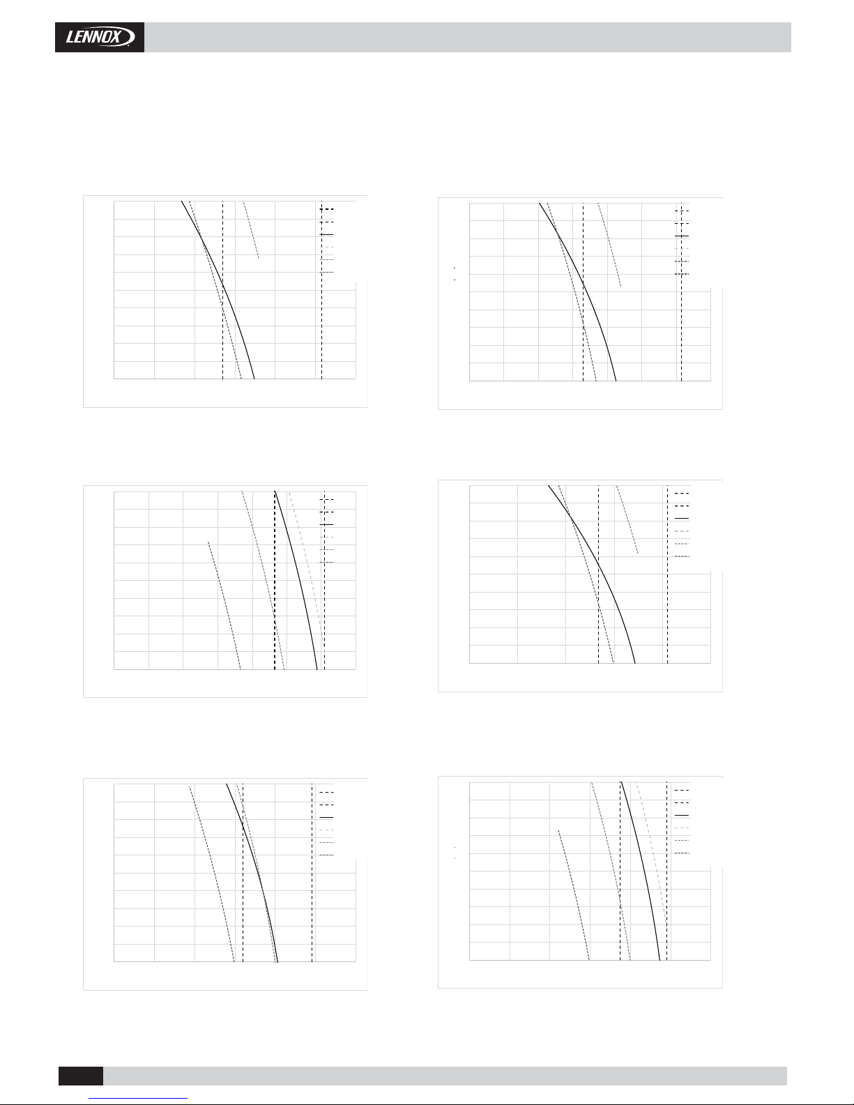
1.- GENERAL CHARACTERISTICS
1.6.- FAN PERFORMANCES.
INDOOR FANS (Nominal speed).
Pressure (Pa)
Air Flow (m 3/h)
Air Flow (m 3/h)
Pressure (Pa)
Air Flow (m 3/h)
Air Flow (m 3/h)
Pressure (Pa)
Pressure (Pa)
Pressure (Pa)
Air Flow (m 3/h)
Air Flow (m 3/h)
Pressure (Pa)
Min Airfl ow
Max Airfl ow
Nominal
100 %
80%
60%
Min Airfl ow
Max Airfl ow
Nominal
100 %
80%
60%
Min Airfl ow
Max Airfl ow
Nominal
100 %
80%
60%
Min Airfl ow
Max Airfl ow
Nominal
100 %
80%
60%
Min Airfl ow
Max Airfl ow
Nominal
100 %
80%
60%
Min Airfl ow
Max Airfl ow
Nominal
100 %
80%
60%
• 13 •
CAMH025SM1M
CASH025SM1M
CAMH035SM1M
CASH035SM1M
CAMH045SM1M
CASH045SM1M
CAMH060DM1M
CASH060DM1M
CAMH075DM1M
CASH075DM1M
CAMH085DM1M
CASH085DM1M
0
50
100
150
200
250
300
350
400
450
500
0 2000 4000 6000 8000 10000 12000
Pressure (Pa)
Air Flow (m3/h)
Min Air Flow
Max Air Flow
Nom Reg
Reg 100%
Reg 80%
Reg 60%
0
50
100
150
200
250
300
350
400
450
500
0 2000 4000 6000 8000 10000 12000 14000
Pressure (Pa)
Air Flow (m3/h)
Min Air Flow
Max Air Flow
Nom Reg
Reg 100%
Reg 80%
Reg 60%
0
50
100
150
200
250
300
350
400
450
500
0 2000 4000 6000 8000 10000 12000 14000
Pressure (Pa)
Air Flow (m3/h)
Min Air Flow
Max Air Flow
Nom Reg
Reg 100%
Reg 80%
Reg 60%
0
50
100
150
200
250
300
350
400
450
500
0 5000 10000 15000 20000 25000
Pressure (Pa)
Air Flow (m3/h)
Min Air Flow
Max Air Flow
Nom Reg
Reg 100%
Reg 80%
Reg 60%
0
50
100
150
200
250
300
350
400
450
500
0 5000 10000 15000 20000 25000 30000
Pressure (Pa)
Air Flow (m3/h)
Min Air Flow
Max Air Flow
Nom Reg
Reg 100%
Reg 80%
Reg 60%
0
50
100
150
200
250
300
350
400
450
500
0 5000 10000 15000 20000 25000 30000
Pressure (Pa)
Air Flow (m3/h)
Min Air Flow
Max Air Flow
Nom Reg
Reg 100%
Reg 80%
Reg 60%
Installation Manual • COMPACTAIR ADV IOM-MIL157E-0418
1.6.- FAN PERFORMANCES.
Pressure (Pa)
Air Flow (m 3/h) Air Flow (m 3/h)
Pressure (Pa)
OUTDOOR FANS.
1.- GENERAL CHARACTERISTICS
Pressure (Pa)
Air Flow (m 3/h)
Air Flow (m 3/h)
Pressure (Pa)
Air Flow (m 3/h)
Air Flow (m 3/h)
Pressure (Pa)
Pressure (Pa)
Min Airfl ow
Max Airfl ow
Nominal
100 %
80%
60%
Min Airfl ow
Max Airfl ow
Nominal
100 %
80%
60%
Min Airfl ow
Max Airfl ow
Nominal
100 %
80%
60%
Min Airfl ow
Max Airfl ow
Nominal
100 %
80%
60%
Min Airfl ow
Max Airfl ow
Nominal
100 %
80%
60%

• 14 •
CH
B12B11
Acumulador
Aspiración
Compresor
Scroll BLDC
Válvula expansión
electrónica
Filtro secador
CH
B12
B11
Acumulador
Aspiración
Compresor
Scroll BLDC
Filtro secador
UNIDAD EXTERIORUNIDAD INTERIOR
Separador de aceite
Filtro secador
Válvula 4 vías
Válvula 4 vías
Válvula retención
Válvula retención
Válvula expansión
electrónica
Válvula expansión
electrónica
BS1
BS1
BS14
BS14
B13
B13
BS13
BS13
B13_1
BS13_1
BS4
BS4
BS2
BS2
Ventilador
PLUG FAN
Ventilador
PLUG FAN
Ventilador
PLUG FAN
Ventilador
PLUG FAN
CH
B11
B12
B13
B13_1
BS1
BS14
BS4
BS2
BS13
BS13_1
Installation Manual • COMPACTAIR ADV IOM-MIL157E-0418
1.- GENERAL CHARACTERISTICS
1.7.- HEAT PUMP PIPING DRAWINGS.
Pressure gauge. (5/16" to be fi tted by the installer).
High pressure switch.
High pressure transducer.
Low pressure transducer.
Crank case heater.
Outdoor temperature sensor.
Unloading sensor.
Suction sensor.
Air return sensor.
Impulsion air sensor.
CAMH025 & CAMH035 & CAMH045
PACKAGE UNITS
PIPING DRAWINGS
CASH/CAIH025 & CASH/CAIH035 & CASH/CAIH045
SPLIT UNITS
PIPING DRAWINGS
 Loading...