


E2012 Lennox Industries Inc.
Dallas, Texas, USA
THIS MANUAL MUST BE LEFT WITH THE HOMEOWNER FOR FUTURE REFERENCE
 WARNING
Improper installation, adjustment, alteration, service or maintenance can cause personal injury, loss of life, or damage to property.
Installation and service must be performed by a licensed professional installer (or equivalent) or a service agency.
 IMPORTANT
The Clean Air Act of 1990 bans the intentional venting of refrigerant (CFCs, HCFCs and HFCs) as of July 1, 1992.
Approved methods of recovery, recycling or reclaiming must be followed. Fines and/or incarceration may be levied for noncompliance.
 WARNING
The State of California has determined that this product may contain or produce a chemical or chemicals, in very low doses, which may cause serious illness or death. It may also cause cancer, birth defects, or reproductive harm.
INSTALLATION
INSTRUCTIONS
Merit® CBX25UH Series
Units
AIR HANDLERS
506757-01 (0659371-80) |
Litho U.S.A. |
|
|
10/2012 |
|
Table of Contents
Shipping and Packing List . . . . . . . . . . . . . . . . . . . . . . 1
CBX25UH Series Units . . . . . . . . . . . . . . . . . . . . . . . . . 1
Requirements . . . . . . . . . . . . . . . . . . . . . . . . . . . . . . . . . 3
Installation Clearances . . . . . . . . . . . . . . . . . . . . . . . . . 3
Installation . . . . . . . . . . . . . . . . . . . . . . . . . . . . . . . . . . . . 4
Condensate Drain . . . . . . . . . . . . . . . . . . . . . . . . . . . . . 6
Duct System and Filters . . . . . . . . . . . . . . . . . . . . . . . . 7
Connecting Refrigerant Lines . . . . . . . . . . . . . . . . . . . 8
Sealing the Unit . . . . . . . . . . . . . . . . . . . . . . . . . . . . . . . 8
Electrical Connections . . . . . . . . . . . . . . . . . . . . . . . . . 9
Airflow - Cooling Blower Speed . . . . . . . . . . . . . . . . . . 10
Check-Out Procedures . . . . . . . . . . . . . . . . . . . . . . . . . 12
Operation . . . . . . . . . . . . . . . . . . . . . . . . . . . . . . . . . . . . 12
Maintenance . . . . . . . . . . . . . . . . . . . . . . . . . . . . . . . . . . 13
Cabinet Insulation . . . . . . . . . . . . . . . . . . . . . . . . . . . . . 13
Shipping and Packing List
Package 1 of 1 contains the following:
1 - Assembled air handler unit for upflow or horizontal air discharge application (includes upflow and horizontal drain pans and pre-installed air filter).
Check equipment for shipping damage. If found, immediately report damage to the last carrier. Check the unit rating plate to confirm that delivered unit matches order.
General
The CBX25UH air handler is designed for indoor installation only. As shipped, the unit is ready for installation in either upflow, horizontal left-hand and right-hand air discharge applications. Electric heat, down flow air discharge application kits, air filters and other various accessories are available and listed in the
CBX25UH Product Specification bulletin for ordering.
All units come with a factory installed check/expansion valve.
10/2012 |
Page 1 |
506757-01 (0659371-80) |
*2P102012* |
*P506757-01* |
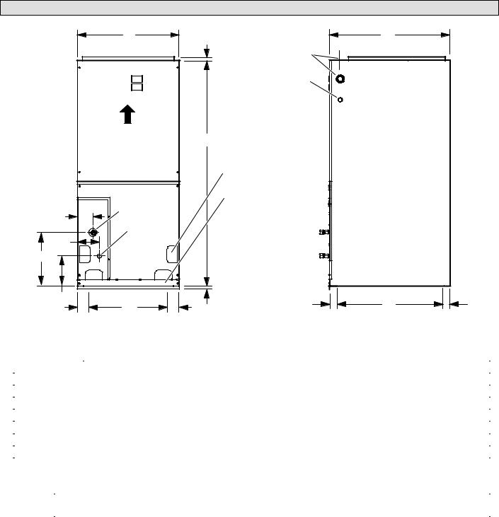
CBX25UH Unit Dimensions - inches (mm)
|
B |
|
3/4 (19) |
C |
|
|
|
|
|
|
|
||
|
|
|
LINE VOLTAGE |
|
|
|
|
|
|
Right, Left and Top |
|
|
|
|
|
|
LOW VOLTAGE |
|
|
|
|
|
|
Right Side Only |
|
|
|
|
AIR FLOW |
|
A |
|
|
|
|
|
|
|
|
||
|
|
|
CONDENSATE DRAIN |
|
|
|
|
|
|
PIPING PLATE (4) |
|
|
|
|
|
|
(2−1/4 x 3−3/4) |
|
|
|
|
|
|
FILTER ACCESS |
|
|
|
|
SUCTION |
|
|
|
|
|
F |
LINE |
|
|
|
|
|
|
LIQUID |
|
|
|
|
|
J |
LINE |
|
|
|
|
|
|
|
|
|
|
||
E |
|
|
|
|
|
|
|
|
|
3/4 |
|
|
|
D |
|
|
(19) |
|
|
|
|
|
|
H |
|
||
|
G |
|
|
|
||
|
|
|
(Opening) |
|
||
2−1/2 |
(Opening) |
2−1/2 |
1−3/4 |
2−1/2 |
||
|
||||||
|
(44) |
|
(64) |
|||
(64) |
|
(64) |
SIDE VIEW |
|||
FRONT VIEW |
|
|
||||
|
|
|
|
|||
|
|
|
|
|
Dimension |
−018 |
|
−024 |
|
−030 |
|
−036 |
|
−042 |
|
−048 / −060 |
|||||||
|
|
|
|
|
|
|
|
|
|
|
|
|
|
|
|
|
||
inches |
|
mm |
inches |
|
mm |
inches |
|
mm |
inches |
|
mm |
inches |
|
mm |
inches |
mm |
||
|
|
|
|
|
|
|
||||||||||||
|
|
|
|
|
|
|
|
|
|
|
|
|
|
|
|
|
|
|
A |
|
38 |
|
965 |
40−1/2 |
|
1029 |
43 |
|
1092 |
48 |
|
1219 |
48 |
|
1219 |
52−1/2 |
1334 |
B |
|
15 |
|
381 |
18−1/2 |
|
470 |
18−1/2 |
|
470 |
21−7/8 |
|
556 |
21−7/8 |
|
556 |
21−7/8 |
556 |
C |
|
22 |
|
559 |
22 |
|
559 |
22 |
|
559 |
22 |
|
559 |
26 |
|
660 |
26 |
660 |
|
|
|
|
|
|
|
|
|
|
|
|
|
|
|
|
|
|
|
D |
|
6 |
|
152 |
6 |
|
152 |
6 |
|
152 |
12−1/4 |
|
311 |
6−1/4 |
|
159 |
6−3/8 |
162 |
|
|
|
|
|
|
|
|
|
|
|
|
|
|
|
|
|
|
|
E |
|
11 |
|
279 |
14 |
|
357 |
16 |
|
406 |
18−7/8 |
|
479 |
17−7/8 |
|
454 |
15−1/4 |
387 |
|
|
|
|
|
|
|
|
|
|
|
|
|
|
|
|
|
|
|
F |
|
3−5/8 |
|
92 |
5−1/2 |
|
140 |
5−1/2 |
|
140 |
5−3/4 |
|
146 |
3−1/4 |
|
83 |
3−1/4 |
83 |
|
|
|
|
|
|
|
|
|
|
|
|
|
|
|
|
|
|
|
G |
|
10 |
|
254 |
13−1/2 |
|
343 |
13−1/2 |
|
343 |
16−7/8 |
|
429 |
16−7/8 |
|
429 |
16−7/8 |
429 |
|
|
|
|
|
|
|
|
|
|
|
|
|
|
|
|
|
|
|
H |
|
17−3/4 |
|
451 |
17−3/4 |
|
451 |
17−3/4 |
|
451 |
17−3/4 |
|
451 |
21−3/4 |
|
552 |
21−3/4 |
552 |
|
|
|
|
|
|
|
|
|
|
|
|
|
|
|
|
|
|
|
J |
|
3−5/8 |
|
92 |
5−1/2 |
|
140 |
5−1/2 |
|
140 |
5−3/4 |
|
146 |
4−5/8 |
|
117 |
6−3/8 |
162 |
|
|
|
|
|
|
|
|
|
|
|
|
|
|
|
|
|
|
|
Supply Air |
Depth |
17 |
|
432 |
17 |
|
432 |
17 |
|
432 |
17 |
|
432 |
21 |
|
533 |
21 |
533 |
Opening |
Width |
13 |
|
330 |
16−1/2 |
|
419 |
16−1/2 |
|
419 |
19−7/8 |
|
505 |
19−7/8 |
|
505 |
19−7/8 |
505 |
|
|
|
|
|
|
|
|
|
|
|
|
|
|
|
|
|
|
|
Return Air |
Depth |
20−3/4 |
|
527 |
20−3/4 |
|
527 |
20−3/4 |
|
527 |
20−3/4 |
|
527 |
24−3/4 |
|
629 |
24−3/4 |
629 |
Opening |
Width |
12−1/2 |
|
318 |
16 |
|
406 |
16 |
|
406 |
19−3/8 |
|
492 |
19−3/8 |
|
492 |
19−3/8 |
492 |
Page 2
Requirements
 WARNING
Excessive Weight Hazard - Use two or more people when moving and installing the unit. Failure to do so can result in back or other type of injury.
 IMPORTANT
The CBX25UH units are designed to match, and must be used with, outdoor units as rated. The indoor sections are manufactured with a check/expansion valve (TXV) to provide optimum refrigerant control and system performance with a variety of different capacities of out door units.
 CAUTION
Physical contact with metal edges and corners while applying excessive force or rapid motion can result in personal injury. Be aware of, and use caution when working near these areas during installation or while servicing this equipment.
These instructions are intended as a general guide and do not supersede local or national codes in any way. Consult authorities having jurisdiction before installation.
Compliance with all local, state, or national codes pertaining to this type of equipment should be determined prior to installation. Read this instruction manual, as well as the instructions supplied in separate equipment, before starting the installation.
In addition to conforming to manufacturer's installation instructions and local municipal building codes, installation of Lennox air handler units (with or without optional electric heat), MUST conform with National Fire Protection Association (NFPA) standards: “Standard for Installation of Air Conditioning and Ventilation Systems” (NFPA No. 90A) and “Standard for Installation of Residence Type Warm Air Heating and Air Conditioning Systems” (NFPA No. 90B).
All models are designed for indoor installation only. The installation of the air handler, field wiring, duct system, etc. must conform to the requirements of the National Electrical
Code, ANSI/NFPA No. 70 (latest edition) in the United States, and any state laws, and local ordinances (including plumbing or wastewater codes). Local authorities having jurisdiction should be consulted before installation is made. Such applicable regulations or requirements take precedence over the general instructions in this manual. Install the conditioned air plenum, ducts and air filters
(provided) in accordance with NFPA 90B Standard for the Installation of Warm Air Heating and Air-Conditioning Systems (latest edition).
The air handler is shipped from the factory completely assembled. The unit is provided with flanges for the connection of the duct system.
Do not remove the cabinet knockouts until it has been determined which knockouts will need to be removed for the installation.
Select the final air discharge position which best suits the site conditions. Consider required clearances, space, routing requirements for refrigerant line, condensate disposal, filters, duct system, wiring, and accessibility for service. Refer to the air handler rating plate on the air handler for specific information.
 WARNING
Danger of explosion. Keep flammable ma terials and vapors, such as gasoline, away from air handler. Place air handler so that heating elements are at least 18 inches (46 cm) above the floor for a garage installa tion. Failure to follow these instructions can result in death, explosion, or fire.
NOTES —
During cooling operation, excessive sweating may occur if the air handler is installed in a warm and humid space.
If installed in an unconditioned space, sealant should be applied around the electrical wires, refrigerant tubing, and condensate lines where they enter the cabinet.
Electrical wires should be sealed on the inside where they exit the conduit opening. Sealant is required to prevent air leakage into, and condensate from forming inside of, the air handler, the control box, and on the electrical controls.
This unit is approved for installation clearance to combustible material as stated on the unit rating plate. Accessibility and service clearances must take precedence over combustible material clearances.
The air handler must be installed so that free access is allowed to the coil/filter compartment and blower/control compartment.
Installation Clearances
NON-DUCTED RETURN CLOSET INSTALLATION
The air handler can be installed in a closet with a false bottom to form a return air plenum. It may also be installed with a return air plenum under the air handler.
Louvers or return air grilles are field supplied. Local codes may limit application of systems without a ducted return to single story buildings.
When a CBX25UH unit is installed in a closet with a louvered return opening, the minimum open area for the louvers will be:
S320 square inches for -018 and -024 models;
S360 square inches for -030 and -036 models;
S450 square inches for -042 thru -060 models.
If the free area is not known, assume a 25% free area for wood or a 75% free area for metal louvers or grilles. Using the louver dimensions and the 25% or 75% assumption, determine if the open area meets the minimum open area listed above.
Page 3
CBX25UH SERIES

If a return air plenum is used, the return air grille should be immediately in front of the opening in the plenum to allow for the free flow of return air. When not installed in front of the opening, there must be adequate clearance around the air handler to allow for the free flow of return air.
Installation
Each unit consists of a blower assembly, refrigerant coil, and controls, in an insulated galvanized steel factory finished enclosure. Knockouts are provided for electrical wiring entrance.
For ease in installation, it is best to make any necessary coil configuration changes before setting air handler in place.
REFRIGERANT METERING DEVICE
CB25UH units are equipped with a factory-installed check expansion valve.
UPFLOW APPLICATION
1.The air handler must be supported on the bottom only and set on solid floor or field supplied support frame.
Securely attach the air handler to the floor or support frame.
2.If installing a unit in an upflow application, remove the
horizontal drain pan. IMPORTANT - The horizontal drain pan is not required in upflow air discharge installations; its removal provides the best efficiency and air flow.
3.Place the unit in the desired location and slope unit as previously mentioned. Connect return and supply air plenums as required using sheet metal screws.
4.Install units that have no return air plenum on a stand that is at least 14” from the floor. This will allow proper air return.
HORIZONTAL DRAIN PAN
IMPORTANT! REMOVE PAN
FOR BEST EFFICIENCY
AND AIR FLOW.
|
HORIZONTAL DRAIN |
|
UPFLOW |
CONNECTIONS |
|
(BOTH SIDES; NOT |
||
DRAIN PAN |
||
USED) |
||
|
UPFLOW DRAIN CON
NECTIONS (BOTH
SIDES; USE ONE SIDE
OR OTHER)
Figure 1. Upflow Configuration
HORIZONTAL APPLICATIONS
 IMPORTANT
When removing the coil, there is possible danger of equipment damage and personal injury. Be careful when removing the coil assembly from a unit installed in rightor left-hand applications. The coil may tip into the drain pan once it is clear of the cabinet. Support the coil when removing it.
ANGLE IRON OR SHEET |
ELECTRICAL INLET CLEAR |
METAL MAXIMUM 1/2” |
ANCE 4 IN. (102 MM) |
LONG SCREW |
|
AIR FLOW |
|
FRONT VIEW |
END VIEW |
Figure 2. Suspending Horizontal Unit
NOTE — When the unit is installed in horizontal applications, a secondary drain pan is recommended. Refer to local codes.
NOTE — This unit may be installed in left-hand or right-hand air discharge horizontal applications. Adequate support must be provided to ensure cabinet integrity. Ensure that there is adequate room to remove service and access panels if installing in the horizontal position.
LEFT-HAND DISCHARGE
1.Determine knockouts required for drain line connections.
2.With access door removed, knock out drain line opening for installing drain lines.
3.Set unit so that it is sloped toward the drain pan end of the unit (see figure 10).
4.The horizontal configuration is shown in figure 3.
AIR FLOW
Drains 
|
|
|
|
|
|
KNOCKOUT |
LEFT HAND DRAINS |
||||
Figure 3. Left Hand Discharge Configuration
Page 4
5.If the unit is suspended, the entire length of the cabinet must be supported. If you use a chain or strap, use a piece of angle iron or sheet metal attached to the unit
(either above or below) to support the length of the cabinet. Use securing screws no longer than 1/2 inch to avoid damaging the coil or filter. See figure 2. Use sheet metal screws to connect the return and supply air plenums as required.
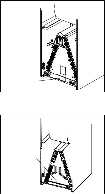
RIGHT-HAND AIR DISCHARGE
For horizontal right-hand air discharge, the following field modifications are required.
1. Remove and set aside blower and coil access covers.
3.Remove coil assembly, bottom drain pan and horizontal drain pan as one assembly from the air handler.
4.Move the horizontal drain pan to the opposite side of the coil. Be sure drain holes toward the back of the unit are plugged. Remove the plugs from the front drain pan ports.
5.Re-install modified coil/drain pan assembly in air handler in the same orientation as before (figures 6 and 7).
2.Remove bracket(s) securing pan(s) to unit as illustrated in figures 4 and 5.
INSTALL BRACKET
SECURING MAIN
DRAIN PAN TO UNIT.
Figure 6. Install Main Drain Pan Mounting Bracket
(-018 through -036)
REMOVE BRACKET SECURING MAIN DRAIN PAN TO UNIT.
Figure 4. Remove Main Drain Pan Mounting Bracket
(-018 through -036)
REMOVE BRACKETS |
|
SECURING BOTH |
|
DRAIN PANS TO UNIT. |
REMOVE BRACKETS |
|
|
|
SECURING BOTH |
|
DRAIN PANS TO UNIT. |
|
Figure 7. Install both Horizontal and Main Drain Pan |
|
Brackets (-042 through -060) |
|
6. Remove two screws securing the blow-off prevention |
Figure 5. Remove Horizontal and Main Drain Pan |
bracket. Rotate the brackets 180º and reinstall using |
Mounting Brackets (-042 through -060) |
the same screws. See figure 8. |
|
Page 5 |
CBX25UH SERIES
 Loading...