


PRODUCT LITERATURE
Lennox Industries Inc.
Dallas, Texas
This boiler cannot be used with all types of chimneys. Read these instructions carefully before installing.
INSTALLATION INSTRUCTIONS
GWB9-050IH-2
GWB9-075IH-2
GWB9-100IH-2
GAS-FIRED, DIRECT VENT,
CONDENSING, HOT WATER BOILER
RETAIN THESE INSTRUCTIONS FOR
FUTURE REFERENCE
These instructions must be affixed on or adjacent to the boiler.
!WARNING
Improper installation, adjustment, alteration, service, or maintenance could result in death or serious injury. Refer to this manual for assistance. For additional information consult a qualified installer, service agency, or the gas supplier.
GAS-FIRED HOT WATER BOILERS
These low pressure gas fired hot water boilers are design certified by CSA (Canadian Standards
Association) for use with natural and propane gases (100 MBH model is certified for natural gas only). They are constructed and hydrostatically tested for a maximum working pressure of 50 psi (pounds per square inch) in accordance with A.S.M.E. (American Society of Mechanical
Engineers) Boiler and Pressure Vessel Code
Section IV Standards for Heating Boilers.
P/N# 240009449, Rev. A [07/2012]

DIMENSIONS
Figure 1 - Boiler Dimensions
2

INTRODUCTION |
|
Dimensions.................................................................................................................... |
2 |
Introduction................................................................................................................... |
3 |
Important Safety Information........................................................................................... |
4 |
Boiler Ratings & Capacities .............................................................................................. |
5 |
Boilers For Use At High Altitude ........................................................................................ |
5 |
Before Installing The Boiler .............................................................................................. |
8 |
Boiler Installation ........................................................................................................... |
9 |
Near Boiler Piping......................................................................................................... |
11 |
Combustion Air And Vent Pipe ........................................................................................ |
22 |
Gas Supply Piping......................................................................................................... |
28 |
Electrical Wiring ........................................................................................................... |
30 |
Controls And Accessories ............................................................................................... |
35 |
Start Up ...................................................................................................................... |
37 |
Operating Instructions................................................................................................... |
38 |
S9381a Integrated Boiler Control Operation And Adjustments............................................. |
39 |
Maintenance And Cleaning ............................................................................................. |
45 |
Troubleshooting............................................................................................................ |
47 |
Differential Air Pressure Switch Check ............................................................................. |
49 |
Appendix A - Water Quality, Water Treatment And Freeze Protection.................................... |
50 |
Installation And Check-Out Certificate ............................................................................. |
54 |
Introduction
•This appliance is a gas-fired direct vent hot water boiler with cast aluminum boiler sections.
•The heating system water absorbs large amounts of heat from the cast aluminum heat exchanger, cooling flue gases and causing condensation.
•Sealed combustion, premix gas burner, and low flame temperature means reduced CO and NOx emissions, which contribute to cleaner and healthier environment.
•This appliance takes its combustion air directly from outdoors (sealed combustion) and does not compete with building occupants for fresh air.
•Sealed combustion (also known as “direct vent”) is safest and best way to obtain plenty of clean combustion air.
•Induced draft fan draws in outside combustion air, takes cooler flue gases from boiler unit and provides positive removal of flue gases from the building through readily available PVC and CPVC pipes.
•These low pressure gas-fired hot water boilers are design certified by CSA International for use with natural gas and propane gases (90-100 model is certified for natural gas only).
•Boilers are constructed and hydrostatically tested for maximum working pressure of 50 psig (pounds per square inch gage) in accordance with A.S.M.E.
(American Society of Mechanical Engineers) Boiler and Pressure Vessel Code Section IV Standards for heating boilers.
3
IMPORTANT SAFETY INFORMATION
General
Boiler installation shall be completed by qualified agency. See glossary for additional information.
! WARNING
Fire, explosion, asphyxiation and electrical shock hazard. Improper installation could result in death or serious injury. Read this manual and understand all requirements before beginning installation.
Keep this manual near boiler
Retain for future reference
Become familiar with symbols identifying potential hazards.
This is the safety alert symbol. Symbol alerts you to potential personal injury hazards. Obey all safety messages following this symbol to avoid possible injury or death.
!DANGER
Indicates a hazardous situation which, if not avoided, WILL result in death or serious injury
! WARNING
Indicates a hazardous situation which, if not avoided, could result in death or serious injury.
! CAUTION
Indicates a hazardous situation which, if not avoided, could result in minor or moderate injury.
NOTICE
Used to address practices not related to personal injury.
Installation shall conform to requirements of authority having jurisdiction or in absence of such requirements:
•United States
•National Fuel Gas Code, ANSI Z223.1/NFPA 54.
•National Electrical Code, NFPA 70.
•Canada
•Natural Gas and Propane Installation Code, CAN/CSA B149.1.
•Canadian Electrical Code, Part I, Safety Standard for Electrical Installations, CSA C22.1
Where required by authority having jurisdiction, installation shall conform to Standard for Controls and Safety Devices for Automatically Fired Boilers, ANSI/ASME CSD-1.
Additional manual reset low water cutoff and/or manual reset high limit may be required.
Requirements for Commonwealth of Massachusetts:
Boiler installation must conform to Commonwealth of Massachusetts code 248 CMR which includes but is not limited to:
• Installation by licensed plumber or gas fitter.
Installers - Follow local regulations with respect to installation of CO (Carbon Monoxide) Detectors. Follow maintenance recommendations“Maintenance And Cleaning” on page 45.
4

BOILER RATINGS & CAPACITIES
Table 1 - SEA LEVEL RATINGS – NATURAL AND PROPANE GASES
Model |
Input |
++ Heating Capacity |
Net AHRI Rating |
Shipping |
Flue Diameter |
|
*(MBH) |
*(MBH) |
*(MBH) |
Weight (lbs.) |
|||
|
|
|||||
|
|
|
|
|
|
|
90-50 |
50 |
45 |
39 |
220 |
2” CPVC & PVC |
|
90-75 |
75 |
68 |
59 |
220 |
2” CPVC & PVC |
|
90-100** |
100 |
90 |
78 |
220 |
2” CPVC & PVC |
|
* 1 MBH = 1,000 Btuh |
|
|
Btuh = British Thermal Units Per Hour |
|
||
** 90-100 model is certified for natural gas only.
++ AFUE (Annual Fuel Utilization Efficiency) and Heating Capacity is based on the D.O.E. (Department of Energy) test procedure.
Heating Capacity indicates the amount of heat available after subtracting losses up the stack. Most of this heat is available to heat water. A small portion is heat from jacket and surfaces of the boiler, and it is assumed that this heat stays in the structure.
Net AHRI rating represents portion of remaining heat that can be applied to heat radiation or terminal units (i.e. finned tube baseboard, cast iron radiators, radiant floor, etc.). The difference between Heating Capacity and Net AHRI Rating, called piping and pickup allowance, establishes reserve for heating volume of water in system and offsetting heat losses from piping.
Net AHRI ratings shown are based on piping and pickup factor of 1.15 in accordance with AHRI Standard as published by Hydronics Institute. Net AHRI rating of boiler selected should be greater than or equal to the calculated peak heating load (heat loss) for building or area(s) served by boiler and associated hot water heating systems. Consult manufacturer before selecting a boiler for installations having unusual piping and pickup requirements.
Boilers are factory equipped for operation at altitudes ranging from 0-5,000 feet above sea level (4,500 feet in Canada).
Boilers for use at high altitude
Canada - Contact Provincial authority having jurisdiction for installations above 4,500 feet (1,350m) above sea level. United States - See “Boilers For Use At High Altitude” on page 6.
5
BOILERS FOR USE AT HIGH ALTITUDE - UNITED STATES INSTALLATIONS
•Boilers (with exception of 90-75 propane (LP) product) are factory equipped for operation at altitudes ranging from 0-10,000 feet above sea level.
•No changes to factory settings are required for installations from 0-5,000 feet above sea level.
•For altitudes from 5,000-10,000 feet above sea level gas manifold pressure needs to be adjusted based upon calorific (Btu) value of supply gas (contact local gas utility or distributor for this value).
•For specific settings refer to Table 2 for natural gas applications and Table 3, Page 7 for propane (LP) gas applications.
•Instructions on how to adjust gas manifold pressure settings see Figure 27 and Figure 28, Page 44.
Note 90-75 propane (LP) applications for 5,000 - 10,000 feet above sea level require orifice change as well as gas manifold pressure adjustment based upon calorific (Btu) value of supply gas.
Refer to Table 2 and Table 3 for high altitude orifice part number. For replacing orifice refer to specific instructions included with conversion kit.
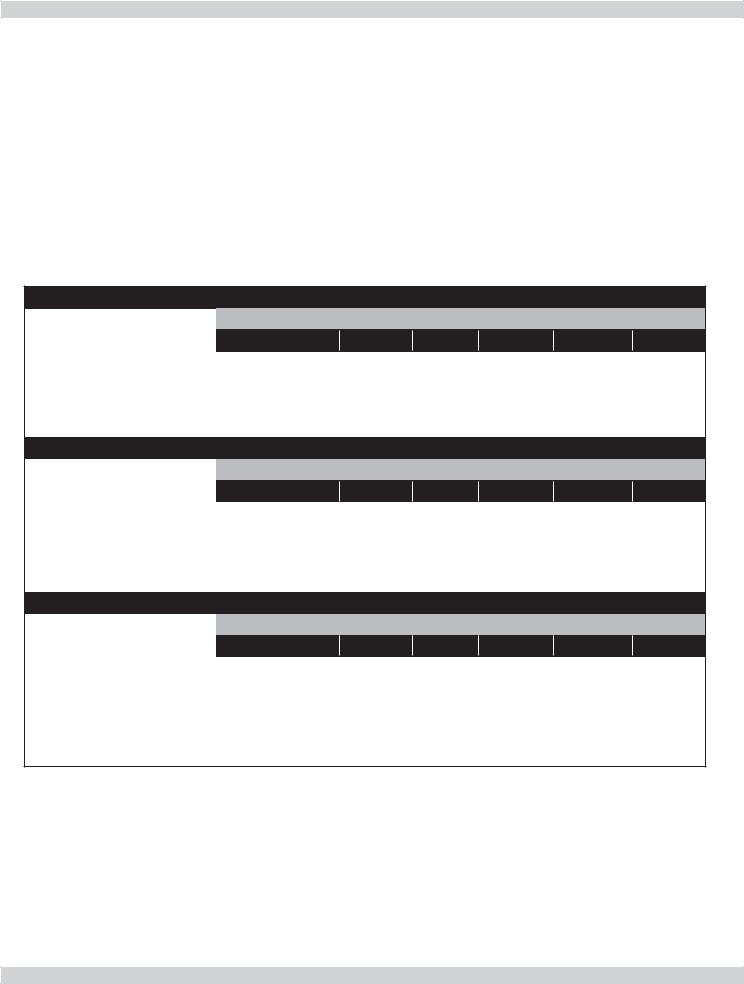
Table 2 - 90 - 50/75/100 SERIES 2 NATURAL GAS
MODEL 90-50
|
Stock Factory |
|
|
Btu Value of Natural Gas++ |
|
|||
|
Settings |
750 |
|
850 |
950 |
|
1000 |
1050 |
Altitude in Ft. |
0-5,000 |
|
|
|
5,000-10,000 |
|
|
|
Normal Input (MBH) |
50 |
– |
|
– |
– |
|
– |
– |
Manifold Pressure In W.C. |
2.5 |
4 |
|
4 |
3.5 |
|
2.5 |
2.5 |
Orifice |
43331094 |
|
|
|
43331094 |
|
|
|
|
MODEL 90-75 |
|
|
|
|
|
||
|
Stock Factory |
|
|
Btu Value of Natural Gas++ |
|
|||
|
Settings |
750 |
|
850 |
950 |
|
1000 |
1050 |
Altitude in Ft. |
0-5,000 |
|
|
|
5,000-10,000 |
|
|
|
Normal Input (MBH) |
75 |
– |
|
– |
– |
|
– |
– |
Manifold Pressure In W.C. |
2.5 |
3.5 |
|
3.5 |
2.5 |
|
2.5 |
2.5 |
Orifice |
43331092 |
|
|
|
43331092 |
|
|
|
|
MODEL 90-100 |
|
|
|
|
|
||
|
Stock Factory |
|
|
Btu Value of Natural Gas++ |
|
|||
|
Settings |
750 |
|
850 |
950 |
|
1000 |
1050 |
Altitude in Ft. |
0-5,000 |
|
|
|
5,000-10,000 |
|
|
|
Normal Input (MBH) |
100 |
– |
|
– |
– |
|
– |
– |
Manifold Pressure In W.C. |
2.5 |
3.5 |
|
3.5 |
2.5 |
|
2.5 |
2.5 |
Orifice |
43331090 |
|
|
|
43331090 |
|
|
|
++Contact local gas utility or distributor for Btu value of gas.
6
BOILERS FOR USE AT HIGH ALTITUDE - UNITED STATES INSTALLATIONS
Model 90-75 propane (LP) units only at altitudes above 5,000 ft., install 90-75 High Altitude Orifice Kit #550002629*.
For all other altitudes use sea level orifice
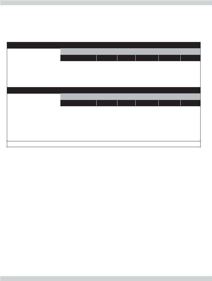
Table 3 - 90 - 50/75 SERIES 2 PROPANE GAS
MODEL 90-50
|
Stock Factory |
|
|
Btu Value of Propane Gas++ |
|
|||
|
Settings |
2300 |
|
2350 |
2400 |
|
2450 |
2500 |
Altitude in Ft. |
0-5,000 |
|
|
|
5,000-10,000 |
|
|
|
Normal Input (MBH) |
50 |
– |
|
– |
– |
|
– |
– |
Manifold Pressure In W.C. |
2.5 |
3 |
|
3 |
2.5 |
|
2.5 |
2.5 |
Orifice |
43331095 |
|
|
|
43331095 |
|
|
|
|
MODEL 90-75* |
|
|
|
|
|
||
|
Stock Factory |
|
|
Btu Value of Propane Gas++ |
|
|||
|
Settings |
2300 |
|
2350 |
2400 |
|
2450 |
2500 |
Altitude in Ft. |
0-5,000 |
|
|
|
5,000-10,000 |
|
|
|
Normal Input (MBH) |
75 |
– |
|
– |
– |
|
– |
– |
Manifold Pressure In W.C. |
2.5 |
3.5 |
|
3.5 |
3.5 |
|
3 |
3 |
Orifice |
43331093 |
|
|
|
43331096* |
|
|
|
* For model 90-75 Propane units only at altitudes above 5,000 ft., install 90-75 High Altitude Orifice Kit #550002629 For all other altitudes use sea level orifice.
++Contact local gas utility or distributor for Btu value of gas.
7

BEFORE INSTALLING THE BOILER
1.Boiler is equipped for residential installations. If used for commercial applications, any additional code requirements must be adhered to for installation. This may require additional controls including but not limited to a low water cut off, a manual reset high temperature limit, and wiring and/or piping modifications.
2.Before servicing boiler - allow boiler to cool. Shut off electricity and gas supply connected to boiler prior to servicing.
3.Inspect gas line for leaks.
4.Verify gas input rate is correct. Over firing may result in early failure of boiler sections. This may cause dangerous operation. Under firing may result in too much air for pre-mix burner causing poor or loss of combustion.
5.Never vent products of combustion from this boiler to enclosed space. Always vent to outdoors. Never vent to another room or to inside building.
6.Be sure there is adequate outdoor air supply to boiler for complete combustion.
7.Follow regular service and maintenance schedule for efficient and safe operation.
8.Keep boiler area clean of debris and free of combustible and flammable materials.
9.Proper through wall or through roof combustion venting shall be in accordance with materials and methods described in this manual. Installation must comply with local codes.
10.Boiler and related hot water heating systems are not do it yourself items they must be installed and serviced by qualified professionals.
Boiler Sizing
Check to be sure you have selected boiler with proper capacity before starting installation. AHRI Rating of boiler selected should be greater than or equal to calculated peak heating load (heat loss) for building or area(s) served by boiler and associated hot water heating systems. See Table 1, Page 5.
Heat loss calculations should be based on approved industry methods.
Boiler Location Considerations
Before selecting boiler location consider following.
•Supplied with correct type of gas (natural gas or propane).
•Connected to suitable combustion air intake piping system to supply correct amounts of fresh (outdoor) air for combustion, refer to “Combustion Air and Vent Pipe” on page 22 for details.
•Connected to a suitable venting system to remove the hazardous products of gas combustion, refer to “Combustion Air and Vent Pipe” on page 22 for details.
•Connected to a suitable hot water heating system.
•Supplied with a suitable electrical supply for all boiler motors and controls.
•Connected to a properly located thermostat or operating control. Not included with boiler.
•Placed on level surface. DO NOT install on carpeting.
•Condensate drain line must be pitched down to floor drain or external condensate pump with reservoir at ¼” per foot (wood frame or blocks may be used to raise boiler).
8
BOILER INSTALLATION
Locating The Boiler
1.Place crated boiler as close to selected location as possible and un-crate boiler. Boiler may be moved into position with appliance dolly or 2 wheel hand truck. Insert dolly or hand truck under left hand side of boiler. It is possible to slide boiler for short distance on smooth floor or surface.
1.Select level location central to piping systems served and as close to vent and air intake terminals as possible.
2.Accessibility clearances, if more stringent (i.e. larger clearances) than required fire protection clearances, must be used for boiler installation. Accessibility clearances may be achieved with the use of removable walls or partitions.
3.Boiler is approved for installation in closets and on combustible floors. This boiler shall NOT be installed on carpeting.
4.Clearances shown in Table 4 indicate required clearances. Maintain minimum 1” clearance between combustible construction and each of left, top and back surfaces of the boiler. Minimum 11” clearance is required on right side, to allow room for induced draft blower. Maintain 18” clearance at side where
passage is required to access another side for cleaning or servicing, inspection or replacement of parts. Allow 24” at front and left side and 8” at top for servicing. No clearances are required to venting or combustion air intake piping.
5.Install equipment in location which facilitates operation of venting and combustion air intake piping systems as described in this manual.
6.Advise owner to keep venting and combustion air intake passages free of obstructions. Both venting and combustion air intake piping systems connected to outdoors must permit flow through piping systems without restrictions for boiler operation.
7.Install boiler such that the automatic gas ignition system components are protected from water (dripping, spraying, rain, etc.) during operation and service (circulator replacement, condensate trap, control replacement, etc.).
Combustion Air And Vent Pipe Requirements
This boiler requires a dedicated direct vent system. In a direct vent system, all air for combustion is taken directly from outside atmosphere, and all flue products are discharged to outside atmosphere.
Terminate combustion air and vent pipe connections in same atmospheric pressure zone, through roof or sidewall (roof termination preferred). See Figure 12 thru Figure 14, pages 24 and 25 for required clearances.
•Keep boiler area clean of debris and free of flammable and combustible materials, vapors and liquids.
•When vent pipe is exposed to temperatures below freezing, such as when it passes through an unheated space or when chimney is used as a raceway, vent pipe must be insulated with 1/2” Armaflex or equivalent.
In extreme cold climate areas, use ¾” Armaflex or equivalent.
! WARNING
Solvent cements are combustible. Keep away from heat, sparks, and open flame. Use only in well ventilated areas. Avoid breathing in vapor or allowing contact with skin or eyes. Failure these instructions could result in fire, personal injury, or death.
•Combustion air must be clean outdoor air. Combustion air must not be taken from inside structure because that air frequently is contaminated by halogens, which include fluorides, chlorides, phosphates, bromides and iodides. These elements are found in aerosols, detergents, bleaches, cleaning solvents, salts, air fresheners, paints, adhesives and other household products.
•Locate combustion air inlet as far away as possible from swimming pool and swimming pool pump house.
•All combustion air and vent pipes must be airtight and watertight. Combustion air and vent piping must also terminate as shown in “Combustion Air and Vent Pipe” section.
•Vent connections serving appliances vented by natural draft shall not be connected into any portion of mechanical draft systems operating under positive pressure.
Table 4 - |
Required Clearances |
||
|
Combustible |
Accessibility, |
|
Unit |
Cleaning, and |
||
|
Clearance |
Servicing |
|
|
|
||
Top |
1” (26mm) |
8” (204mm) |
|
|
|
|
|
Left Side |
1 “ (26mm) |
24” (610mm) |
|
Right Side |
11” (280mm) |
- |
|
|
|
|
|
Base |
1” (26mm) |
- |
|
Front |
1” (26mm) |
24” (610mm) |
|
Back |
1” (26mm) |
- |
|
Intake/Vent Piping |
0 (0) |
- |
|
Near Boiler Hot |
1” (26mm) |
- |
|
Water Piping |
|||
|
|
||
All distances measured from the cabinet of the boiler.
9
BOILER INSTALLATION
Condensate Drain Requirements
•Pitch condensate drain line down to floor drain at minimum of ¼” per foot. External condensate pump (not furnished) may be used if floor drain is not available.
•Condensate pump must be designed for flue gas condensate application.
•Condensate trap provided with boiler, an additional trap is not required and should not be used.
•Wood frame or blocks may be used to raise boiler to maintain drain pitch or to be above external condensate pump reservoir.
Foundation Requirements
• Install boiler on level surface.
! WARNING
Fire hazard. Do not install boiler on carpeting. Failure to follow these instructions could result in death or serious injury.
•Boiler is NOT to be installed on carpeting.
•If boiler is not level condensate drain lines will not function properly. Adjustable feet are located on the boiler to make up for minor surface irregularities or tilt.
•Wood frame or blocks may be used to raise boiler to maintain drain pitch or to be above external condensate pump reservoir.
Removal of Existing Boiler From Common Vent System
When an existing boiler is removed from a common venting system, the common venting system is likely to be too large for proper venting of the appliances remaining connected to it. At the time of removal of an existing boiler, the following steps shall be followed with each appliance remaining connected to the common venting system placed in operation, while the other appliances remaining connected to the common venting system are not in operation.
1.Seal any unused openings in the common venting system.
2.Visually inspect the venting system for proper size and horizontal pitch and determine there is no blockage, or restrictions, leakage, corrosion and other deficiencies which could cause an unsafe condition.
3.In-so-far as is practical, close all building doors and windows and all doors between the space in which the appliances remaining connected to the common venting system are located and other spaces of the building. Turn on clothes dryer and any appliance not connected to the common venting system. Turn on any exhaust fans, such as range hoods and bathroom exhaust, so they will operate at maximum speed. Do not operate a summer exhaust fan. Close fire dampers.
4.Place in operation the appliance being inspected. Follow the lighting instructions. Adjust thermostat so appliances will operate continuously.
5.Test for spillage at the draft hood relief opening after 5 minutes of main burner operation. Use the flame of a match or candle, or the smoke from a cigarette, cigar or pipe.
6.After it has been determined that each appliance remaining connected to the common venting system properly vents when tested as outlined above, return doors, windows, exhaust fans, fire place dampers, and any other gas-burning appliance to their previous condition of use.
7.Any improper operation of the common venting system should be corrected so the installation conforms with the National Fuel Code, NFPA-54/ANSI -Z223.1 and/ or the Natural Gas and Propane Installation Code, CAN/CSA B149.1.. When re-sizing any portion of the common venting system, the common venting system should be re-sized to approach the minimum size as determined using the appropriate tables in Chapter 13 of the National Fuel Gas Code, NFPA-54/ANSI- Z223.1 and/or the Natural Gas and Propane Installation Code, CAN/CSA B149.1.
10
NEAR BOILER PIPING
Clean the System First
Before connecting boiler to heating system, clean and flush system thoroughly. Verify system is free of sediment, flux and any residual boiler water additives.
Systems having antifreeze not recommended must be completely flushed to insure no old antifreeze remains. In older systems obviously discolored, murky or dirty water; or pH reading outside acceptable range (between 7.0 and 8.0) are indications the system should be cleaned or treated. Thoroughly flush system with clean water to remove any sediment or contaminants. Sludge and iron oxide deposits can cause rapid breakdown of inhibitors.
Flushing with clean water. If chemical cleaners are used, use only those recommended for use with aluminum boilers. Follow chemical cleaner manufacturer’s instructions completely.
DO NOT mix different manufacturer’s products.
•When boiler installation is for new heating system, install all of radiation units (panels, radiators, baseboard, or tubing) and supply and return mains.
•After all heating system piping and components have been installed, make final connection of system piping to boiler. A hot water boiler installed above radiation level, or as required by the Authority having jurisdiction, must be equipped with low water cut off device.
•Periodic inspection is necessary for flushing of float type devices, per low water cut off manufacturers specific instructions.
Supply And Return Lines
•Boiler is set up to receive 1 ¼” NPT supply and return piping from top access.
•Boiler may be piped from left side by turning supply elbow.
•Install furnished dielectric unions at boiler supply and return lines prior to making system piping connections
•Do Not install copper supply and return piping directly into aluminum boiler section casings due to galvanic corrosion between dissimilar metals.
•Must use provided dielectric unions between copper system piping and boiler to make final connection to boiler.
•Furnished circulator pump can be installed at installer preferred location.
11
NEAR BOILER PIPING
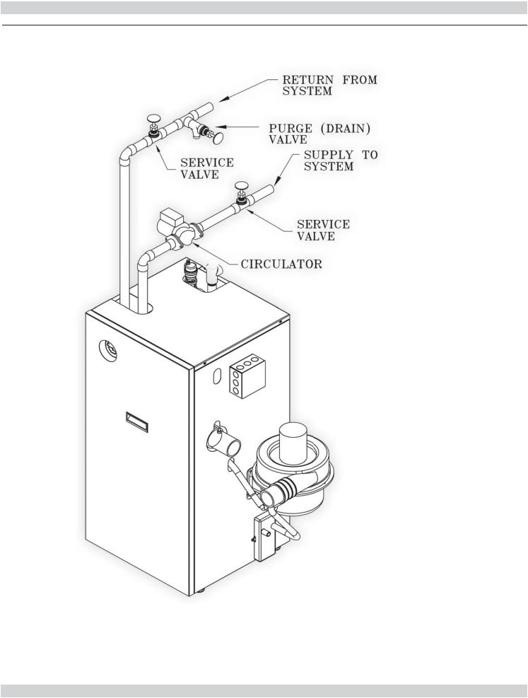
Figure 2 - Single Zone Boiler Piping
12
NEAR BOILER PIPING
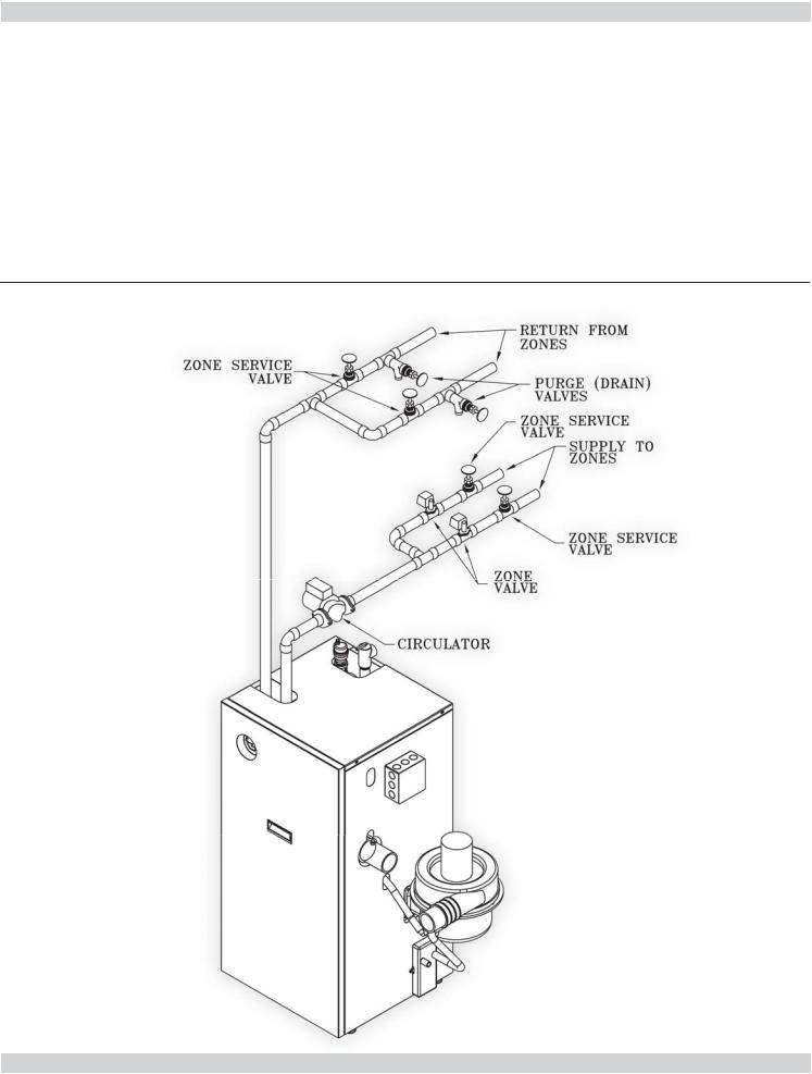
Multi-Zone Systems
Multi-zone systems with two zones are typically piped as shown in figures 3 or 4. Multi-zone systems with more than two zones are likely to have small zones with very low heat and flow requirements compared to full heating capacity of the boiler. This can result in very low flow in the boiler if only one small zone is calling for heat.
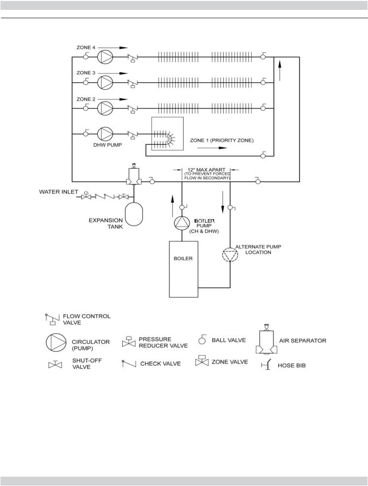
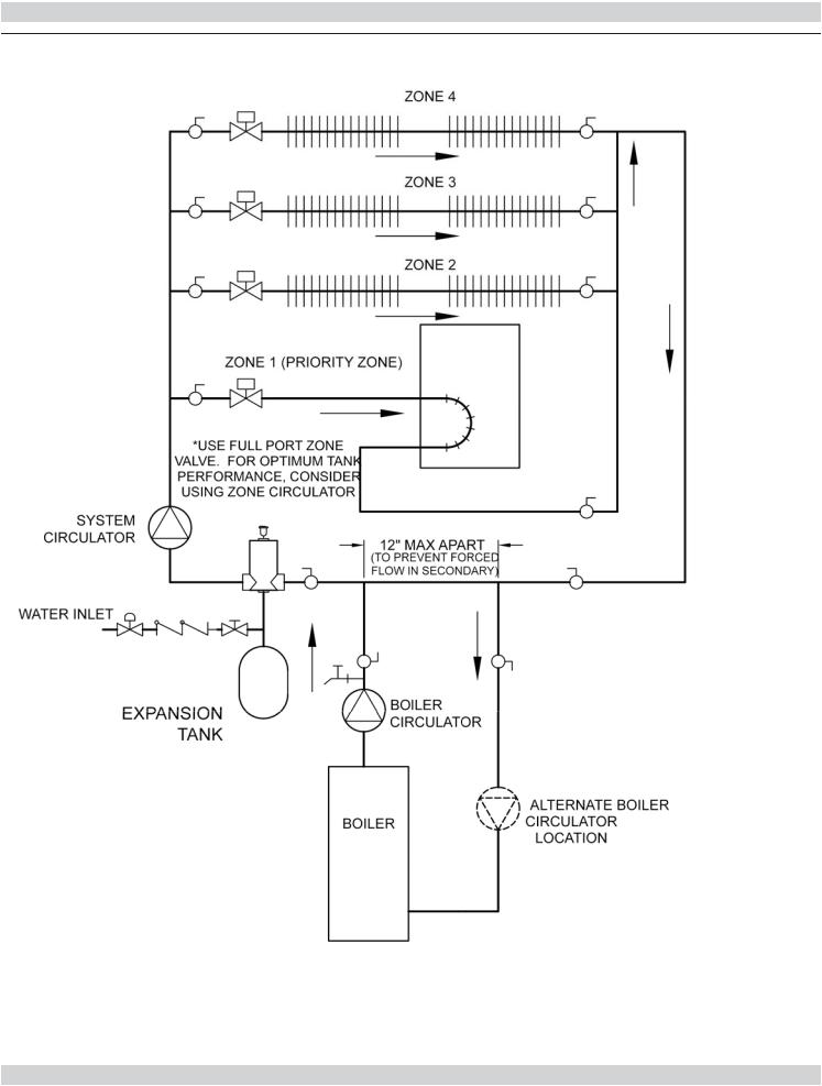
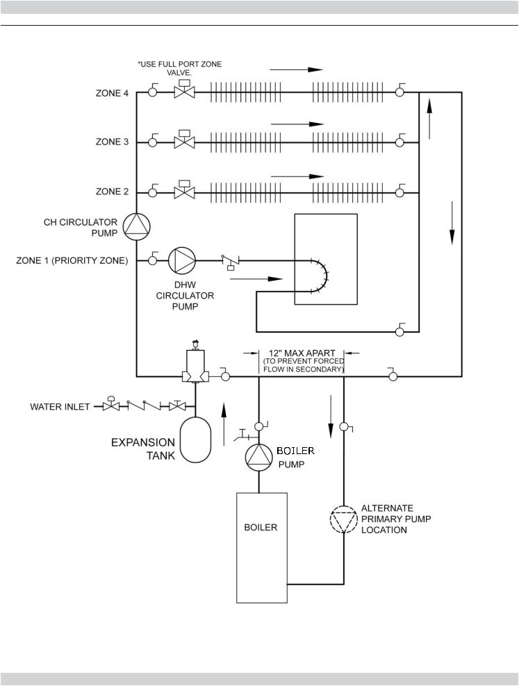
Primary Secondary Piping is recommended for multi-zone systems with more than two zones to insure proper water flow through the boiler at all times. See figures 5, 6 and 7 for typical primary secondary piping configurations.
Figure 3 - Two Zone Boiler Piping With Zone Valves
13
NEAR BOILER PIPING
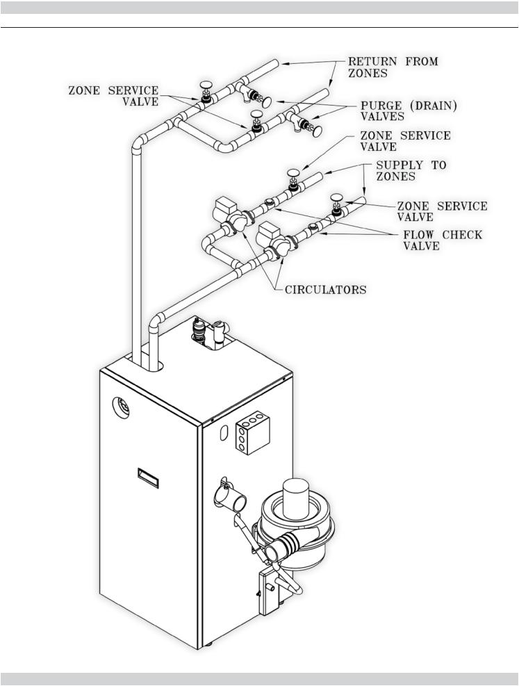
Figure 4 - Two Zone Boiler Piping With Circulators
14
NEAR BOILER PIPING
Figure 5 - Primary/Secondary Piping And Wiring With Circulators And Domestic Hot
Water
15
NEAR BOILER PIPING
Figure 6 - Piping and Wiring Primary/Secondary Multi Zone System Piping With Zone Valves And Domestic Hot Water (With Zone Valve)
16
NEAR BOILER PIPING
Figure 7 - Piping And Wiring Primary/Secondary Piping With Zone Valves And Domestic Hot Water (With Circulator)
17
 Loading...