


50403020
GPS System 500
Technical Reference Manual
Version 4.0
English

System GPS500
Congratulations on your purchase of Leica System 500
To use equipment in the permitted manner, please refer to
the detailed safety instructions in the User Manual.
2
Technical Reference Manual-4.0.0en

Technical Support
Technical Support is provided by Leica Geosystem’s worldwide network of
representatives. We are represented in almost every country in the world. A
representative directory is available at:
www.leica-geosystems.com
Technical Reference Manual-4.0.0en
3

Symbols used in this manual
Important paragraphs which must be adhered to in practice
as they enable the product to be used in a technically
correct and efficient manner.
Symbols used in this manual
4
Technical Reference Manual-4.0.0en

View of chapters
Chapter 1 - Introduction
Chapter 2 - Equipment Setup and Connection
Chapter 3 - Using System 500 without a Terminal
Chapter 4 - TR500 Terminal Overview
Chapter 5 - Configuring the Receiver
Chapter 6 - Jobs and Points
Chapter 7 - Measuring with System 500
Chapter 8 - Coding
Chapter 9 - The CONFIG key
Chapter 10 - Status
Chapter 11 - Applications
Chapter 12 - Utilities
Chapter 13 - Transfer
11
20
70
74
86
156
158
232
241
259
273
307
310
Technical Reference Manual-4.0.0en
Appendices
321
5
View of chapters

Contents
1. Introduction ..............................................11
1.1 The GPS Antenna ............................................... 12
1.2 The GPS Receiver............................................... 13
1.3 The TR500 Terminal ............................................ 15
1.4 Data Storage ....................................................... 16
1.5 Batteries/Power Supply ........................................ 18
1.5.1 Charging the Batteries ......................................... 19
2. Equipment Set Up and Connection ....... 20
2.1 GPS Receiver ports ............................................. 21
2.2 Equipment Setup - Post Processed Static/Rapid
Static/Reference on Pillar .................................... 22
2.3 Equipment Setup - Post Processed Static/Rapid
Static/Reference on Tripod .................................. 25
2.4 Equipment Setup - Post Processed Kinematic,
Minipack and Pole ............................................... 28
2.5 Equipment Setup - Post Processed Kinematic,
All on Pole, Direct Clip of TR500 on to Sensor...... 32
2.6 Equipment Setup - Post Processed Kinematic,
All on Pole, TR500 and Sensor separated ............ 35
2.7 Equipment Setup - Real Time Reference,
single tripod ....................................................... 38
2.8 Equipment Setup - Real-Time Reference,
Two Tripods ...................................................... 41
2.9 Equipment Setup - Real-Time Rover,
Pole and Minipack ............................................... 44
2.10 Equipment Setup - Real-Time Rover,
All on Pole, direct clip of TR500 on to Sensor ....... 48
2.11 Equipment Setup - Real-Time Rover,
All on Pole, TR500 and Sensor separated ............ 51
2.12 Equipment Setup - Real Time Rover, GIS Rover . 54
2.13 Equipment Setup - Repeater Station and
Repeater Box ...................................................... 58
2.14 Using the Minipack ............................................ 61
2.15 Measuring Antenna Heights ............................... 63
2.15.1 Mechanical Reference Planes ........................... 64
2.15.2 Antenna Height components ............................. 65
2.15.3 Measuring Slope Heights ................................... 69
3. Using System 500 without a Terminal ... 70
3.1 Setting up the Equipment ..................................... 71
3.2 Operation ............................................................ 71
3.3 Shut Down........................................................... 71
3.4 LED Indicators ..................................................... 72
3.4.1 Power LED .......................................................... 72
3.4.2 Satellite Status LED ............................................. 72
3.4.3 Memory Status LED ............................................ 73
3.5 Field Record Sheet .............................................. 73
4. TR500 Terminal Overview ....................... 74
4.1 Screen Layout ..................................................... 75
4.2 Status Icons ........................................................ 77
4.3 Keyboard ............................................................. 82
4.4 General Operating Principles ............................... 83
Contents
6
Technical Reference Manual-4.0.0en

Contents, continued
5. Configuring the Receiver........................ 86
5.1 Configuring the Receiver for Static and Rapid Static
Operations .......................................................... 88
5.1.1 Advanced Operation Mode for Static and Rapid
Static .................................................................... 95
5.2 Configuring the Receiver for Post-Processed
Kinematic Operations .......................................... 99
5.2.1 Advanced Operation Mode for Post-Processed
Kinematic ........................................................... 112
5.3 Configuring the Receiver for Real-Time Reference
Operations ......................................................... 116
5.3.1 Advanced Operation Mode for Real Time
Reference Stations ............................................. 124
5.4 Configuring the Receiver for Real-Time Rover
Operations ........................................................ 127
5.4.1 Advanced Operation Mode for Real Time Rover 148
6. Jobs and Points..................................... 156
6.1 Management of Jobs ......................................... 156
7. Measuring with System 500 ................. 158
7.1 Static and Rapid Static Survey, Post-Processed
Kinematic Reference ......................................... 159
7.1.1 Overview of Procedure ...................................... 160
7.1.2 Adding the Point Id ............................................ 160
7.1.3 Adding the Antenna Height ................................ 161
7.1.4 Adding a Code ................................................... 161
7.1.5 Adding a Starting Time ...................................... 163
7.1.6 Measuring procedure ......................................... 163
7.1.7 Using the ADD key ............................................ 166
7.2 Post-processed Kinematic Survey (Rover) ......... 167
7.2.1 Overview of Procedure ...................................... 168
7.2.2 Adding the Point Id ............................................ 168
7.2.3 Adding the Antenna Height ................................ 169
7.2.4 Adding a Code ................................................... 170
7.2.5 Adding a Starting Time ...................................... 171
7.2.6 Measuring Procedure ........................................ 172
7.2.7 Using the AUTO key .......................................... 174
7.2.8 Using the ADD key ............................................ 174
7.3 Real-Time Reference Stations ........................... 176
7.3.1 Measuring procedure ......................................... 177
7.3.2 Using the ADD key ............................................ 180
7.4 Real-Time Rover, Surveying New Points ............ 181
7.4.1 Overview of Procedure ...................................... 182
7.4.2 Adding the Point Id ............................................ 182
7.4.3 Adding the Antenna Height ................................ 183
7.4.4 Adding a Code ................................................... 184
7.4.5 Adding a Starting Time ...................................... 185
7.4.6 Measurement Procedure ................................... 186
7.4.7 Using the AUTO key .......................................... 190
7.4.8 Using the INIT key ............................................. 193
7.4.9 Using the ADD key ............................................ 194
7.4.10 Using the NEAR key ........................................ 206
7.4.11 Radio Down Infill .............................................. 206
Technical Reference Manual-4.0.0en
7
Contents

Contents, continued
7.5 Real-Time Rover, Staking Out ............................ 208
7.5.1 Entering Stakeout .............................................. 208
7.5.2 Stake-Out Types ................................................ 209
7.5.3 The Stake-Out Screen ....................................... 210
7.5.4 Orientation ......................................................... 211
7.5.5 Polar and Orthogonal ........................................ 215
7.5.6 Using the Reverse function ................................ 216
7.5.7 Using the Redraw function ................................. 217
7.5.8 Picking up a new point ....................................... 217
7.5.9 Using the INIT key ............................................. 217
7.5.10 Using the NEAR key ........................................ 218
7.5.11 Graph .............................................................. 218
7.5.12 Aux Pt .............................................................. 219
7.5.13 Point Stake-Out - Procedure ............................ 220
7.5.14 Slope Stake-Out - Procedure ........................... 222
7.5.15 Grid Stake-Out - Procedure ............................. 226
8. Coding .................................................... 232
8.1 Thematical Coding ............................................. 232
8.1.1 Importing, Selecting and Defining a
Thematical Codelist ............................................ 233
8.1.2 Defining New Codes and Attributes ................... 234
8.1.3 Defining and Activating/Deactivating Layers ...... 235
8.1.4 Adding a Thematical Code to a Point ................. 236
8.2 Free Coding ...................................................... 237
8.2.1 Importing, Selecting and Defining a
Free Codelist ...................................................... 237
8.2.2 Defining New Codes .......................................... 238
8.2.3 Adding a Free Code .......................................... 239
9. The CONFIG Key ................................... 241
9.1 Survey - Satellite ................................................ 242
9.2 General - Units .................................................. 243
9.3 General - Language ........................................... 244
9.4 General - Hot Keys ............................................ 244
9.5 General - Time and Initial Position ...................... 245
9.6 General - Start-Up ............................................. 245
9.7 General - TR500 ................................................ 246
9.8 General - Identification ....................................... 247
9.9 Interfaces ......................................................... 247
9.10 Interfaces - Real-Time ..................................... 247
9.11 Interfaces - NMEA Output ................................ 248
9.12 Interfaces - ASCII Input .................................... 249
9.13 Interfaces - Hidden Point .................................. 253
9.14 Interfaces - GSI/User Out................................. 253
9.15 Interfaces - Remote ......................................... 254
9.16 Interfaces - PPS Out ........................................ 255
9.17 Interfaces - Event Input .................................... 256
10. Status ................................................... 259
10.1 Real-Time Input Status .................................... 259
10.2 Stop and Go Indicator ...................................... 261
10.3 Position ........................................................... 263
10.4 Logging Status ................................................. 266
10.5 Satellite Status ................................................. 267
10.6 Point Log Status .............................................. 269
Contents
8
Technical Reference Manual-4.0.0en

Contents, continued
10.7 Code Log Status .............................................. 270
10.8 Message Log Status ........................................ 270
10.9 Memory/Battery Status ..................................... 270
10.10 Sensor Status ................................................ 271
10.11 Software Version Status ................................. 271
10.12 Interfaces Status ............................................ 272
11. Applications ......................................... 273
11.1 Determining a Coordinate System .................... 273
11.2 Adding Points to Existing Coordinate Systems .. 283
11.3 Point Management ........................................... 284
11.4 Calculator ........................................................ 288
11.5 Wake-up Sessions ........................................... 288
11.6 COGO ............................................................. 290
11.7 Area ................................................................ 303
11.8 Line Division .................................................... 304
12. Utilities ................................................. 307
12.1 Directory of Memory Device ............................. 307
12.2 Format Memory Module ................................... 308
12.3 Enter Security Code ......................................... 309
12.4 Self Test .......................................................... 309
13. Transfer ................................................ 310
13.1 Job .................................................................. 310
13.2 Config Set ....................................................... 310
13.3 Coordinate System ........................................... 311
13.4 Antenna Info ..................................................... 311
13.5 Codelist ............................................................ 311
13.6 ASCII/GSI to Job ............................................ 312
13.7 GSI / User ....................................................... 314
13.8 Geoid Field File................................................ 316
13.9 CSCS Field File ............................................... 316
13.10 Firmware ....................................................... 316
13.11 Firmware TR500 ............................................ 317
13.12 Language Version .......................................... 317
13.13 Application Text .............................................. 317
13.14 Almanac ........................................................ 318
13.15 Account File ................................................... 318
13.16 CFC Log Mask File ........................................ 318
13.17 Beacon Station List ....................................... 319
13.18 Modem/GSM Station List ............................... 319
13.19 System ......................................................... 319
13.20 Any File Type ................................................. 320
Appendix A - Operating and Storage
Temperatures ............................................. 321
Appendix B - Observation Times ............. 322
Appendix C - Seismic Record Format ..... 323
Appendix D - Defined Line File Format ... 324
Technical Reference Manual-4.0.0en
9
Contents

Contents, continued
Appendix E - NMEA Message Formats .... 325
GGA - Global Positioning System Fix Data ............... 327
GGK - Real-Time Position with DOP ........................ 328
GGK(PT) - Real-Time Position with DOP ................. 328
GGQ - Real-Time Position with CQ .......................... 329
GLL - Geodetic Position - Latitude, Longitude ........... 329
GNS - GNSS Fix Data ............................................. 330
GSA - GPS DOP and Active Satellites ..................... 330
GSV - GPS Satellites in View ................................... 331
LLK - Leica Local Position and GDOP ...................... 331
LLQ - Leica Local Position and Quality ..................... 332
VTG - Course Over Ground and Ground Speed ....... 332
ZDA - Time and Date............................................... 333
Appendix F - Pin Assignments and
Sockets ...................................................... 334
Appendix G - Data Device Directory
Structure .................................................... 336
Appendix H - External Devices................. 338
RS232 .................................................................... 339
Radio and Repeaters............................................... 340
GSM ....................................................................... 344
Modem ................................................................... 350
RTB Module (CSI) ................................................... 352
RTS Module (Racal) ................................................ 354
SAPOS ................................................................... 356
Using a SAPOS decoder box ..................................... 356
Using a SMARTgate box ............................................ 357
Using the Telemax Service ......................................... 359
Hidden Point ........................................................... 361
Appendix I - MC500 ................................... 364
Appendix J - RS500 ................................... 369
Appendix K- GS50 / GS50+ and GIS Data
Collection ................................................... 377
Hardware and Accessories ...................................... 378
Compact Flash and Sensor Transfer........................ 382
Operation and Configuration .................................... 383
The CONFIG Key .................................................... 384
The STATUS Key .................................................... 388
Data Collection with the GS50 and GS50+ ............... 389
10
Technical Reference Manual-4.0.0en
1. Introduction
System 500 is used to receive signals
from GPS satellites which are then
processed to obtain a position on the
earth’s surface.
It can be used in many applications,
the main ones being Land Survey,
Stakeout and Hydrographic Survey.
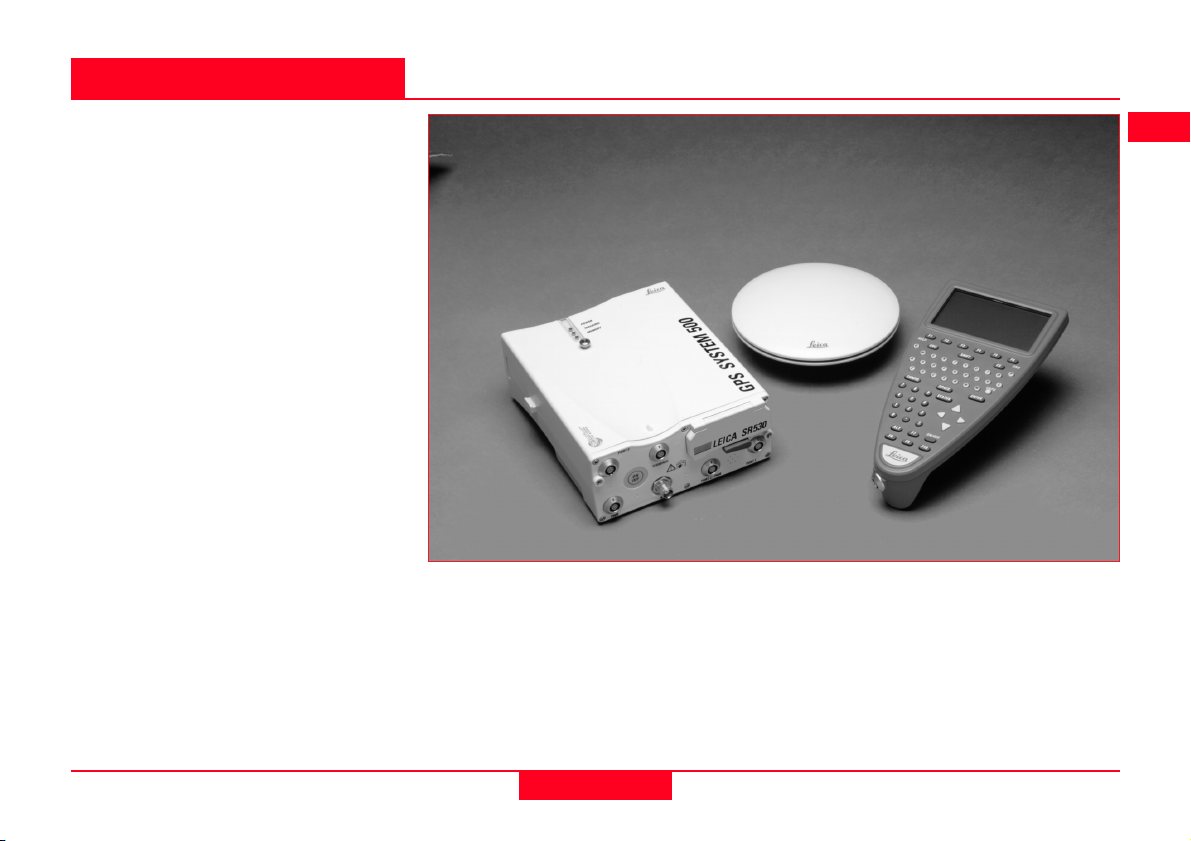
The main components of System 500
are the GPS Antenna and GPS
Receiver. Ancilliary components are
the Terminal, Batteries, PC Cards and
cables.
SKI-Pro, a PC based software is also
used in conjunction with the hardware
listed above for post-processing GPS
data and for downloading coordinates
recorded in the field. Instructions for
using SKI-Pro can be found in the
accompanying printed guides and online help.
System 500 - main hardware components
Technical Reference Manual-4.0.0en
11
1. Introduction

1.1 The GPS Antenna
There are several System 500 GPS
Antennas available. These are:
• AT501 Single Frequency Antenna.
• AT502 Dual Frequency Antenna.
• AT503 Dual Frequency Choke
Ring Antenna.
• AT504 JPL Design Dual Frequency Choke Ring Antenna.
• Single Frequency Choke Ring
Antenna.
The GPS Antenna is selected for use
based upon the application. The vast
majority of applications will require
the AT501 or AT502 Antenna.
The AT501 is a L1 single frequency
antenna. Use it with the SR510
Receiver. The AT502 is a dual frequency antenna. Use it with the
SR520 or SR530 Receiver.
The Choke Ring Antennas are
designed for use where the utmost
precision is required. Typical applications include Static Surveys of long
baselines, Tectonic Plate monitoring,
Reference Stations, etc.
Use the AT503 and AT504 with the
SR520 or SR530 Receiver. Use the
Single Frequency Choke Ring with
the SR510 Receiver.
Also available is a combined GPS/
RTB or GPS/ RTS antenna. Refer to
Appendix K for further information.
AT502 Antenna
1. Introduction
12
AT504 Antenna
Technical Reference Manual-4.0.0en

1.2 The GPS Receiver
The GPS Receiver is the instrument
that processes the GPS signals
received by the GPS Antenna.
There are six different models of GPS
receiver in System 500. The model
number is printed on the PC card lid.
See the detailed descriptions of each
of these receivers given down below.
SR510 - Tracks the L1 C/A code and
uses it to reconstruct the carrier
phase. Data can be stored for postprocessing in SKI-Pro. Baselines can
be calculated with a precision of up to
about 5-10mm +2ppm.
With a radio modem attached the
receiver can be used for real-time
measurements accepting RTCM code
corrections. Coordinates can be
calculated with a precision of up to
about 0.5m.
SR520 - Tracks the L1 C/A code and
L2 P-code to reconstruct the carrier
phase. When Anti-Spoofing (A-S) is
activated, the receiver switches to a
patented P-code aided tracking
technique that provides full L2 carrier
measurements and L2
pseudoranges. Data can be stored for
post-processing. Baselines can be
calculated with a precision of up to
about 3-10mm +1ppm.
With a radio modem attached the
receiver can be used for real-time
measurements accepting RTCM
code corrections. Coordinates can be
calculated with a precision of up to
about 0.5m.
SR530 - Tracks the L1 C/A code and
L2 P-code to reconstruct the carrier
phase. When Anti-Spoofing (A-S) is
activated, the receiver switches to a
patented P-code aided tracking
technique that provides full L2 carrier
measurements and L2
pseudoranges. A radio modem
attaches and the receiver can be
used for RTK operations. Coordinates
can be calculated with a precision of
up to about 1cm
Data can also be stored for postprocessing. Baselines can be calculated with a precision of up to about
3-10mm +1ppm.
System 500 GPS Receivers can be
operated with or without the TR500
Terminal (see section 1.3). The
TR500 is used for field data acquisition and for configuring the receiver.
Details of using the Receiver without
a Terminal are given in Chapter 3.
Technical Reference Manual-4.0.0en
13
1. Introduction

MC500 - A ruggedized version of the
SR530 designed specifically for
Machine Control. Can also be utilised
as a dedicated GPS Reference
Station. Please refer to Appendix I for
specific details.
RS500 - A dedicated GPS Reference
Sation receiver designed for permanent installation. Please refer to
Appendix J for specific details.
GS50 - This receiver has been
specifically designed for GIS applications. Please refer to Appendix K for
more information that is specific to
the GS50 and the corresponding PCsoftware GIS DataPRO.
1. Introduction
14
Technical Reference Manual-4.0.0en
1.3 The TR500 Terminal
The TR500 Terminal provides a full
user interface to all System 500 GPS
Receivers.
It can be used to set parameters in
the receiver and to steer the GPS
measurement operation.
The TR500 can be used to set and
store parameters in one GPS receiver
and then removed and used to set
parameters in another System 500
receiver. The receiver can then be
used in the field without the TR500
attached. Note that whilst this is
possible when measuring in any
mode, for a Reference or Rover, it is
recommended that the Receiver only
be used without a TR500 at Reference stations or with Static/Rapid
Static Rovers.
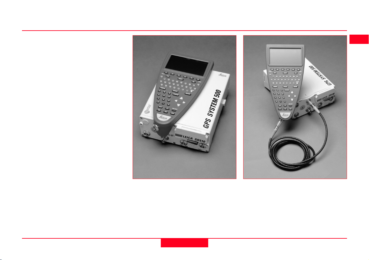
The TR500 is connected either
directly to the receiver or via a cable.
Data input is via a fully alphanumeric
QWERTY keyboard and an LCD
display of 32 x 12 characters which
may be illuminated.
TR500 mounted on the Receiver TR500 connected using the cable
Technical Reference Manual-4.0.0en
15
1. Introduction
1.4 Data Storage
Data is stored on either an Internal
Memory or PC Card. The PC Card is
the preferred data storage medium.
The Internal Memory is an option.
The PC Card is inserted into the slot
on the front of the GPS Receiver. PC
Cards are available from Leica with
varying capacities. Note that whilst
other PC Cards may be used, Leica
recommend Leica PC cards only and
cannot be held responsible for data
loss or any other error that may occur
whilst using a non-Leica card.
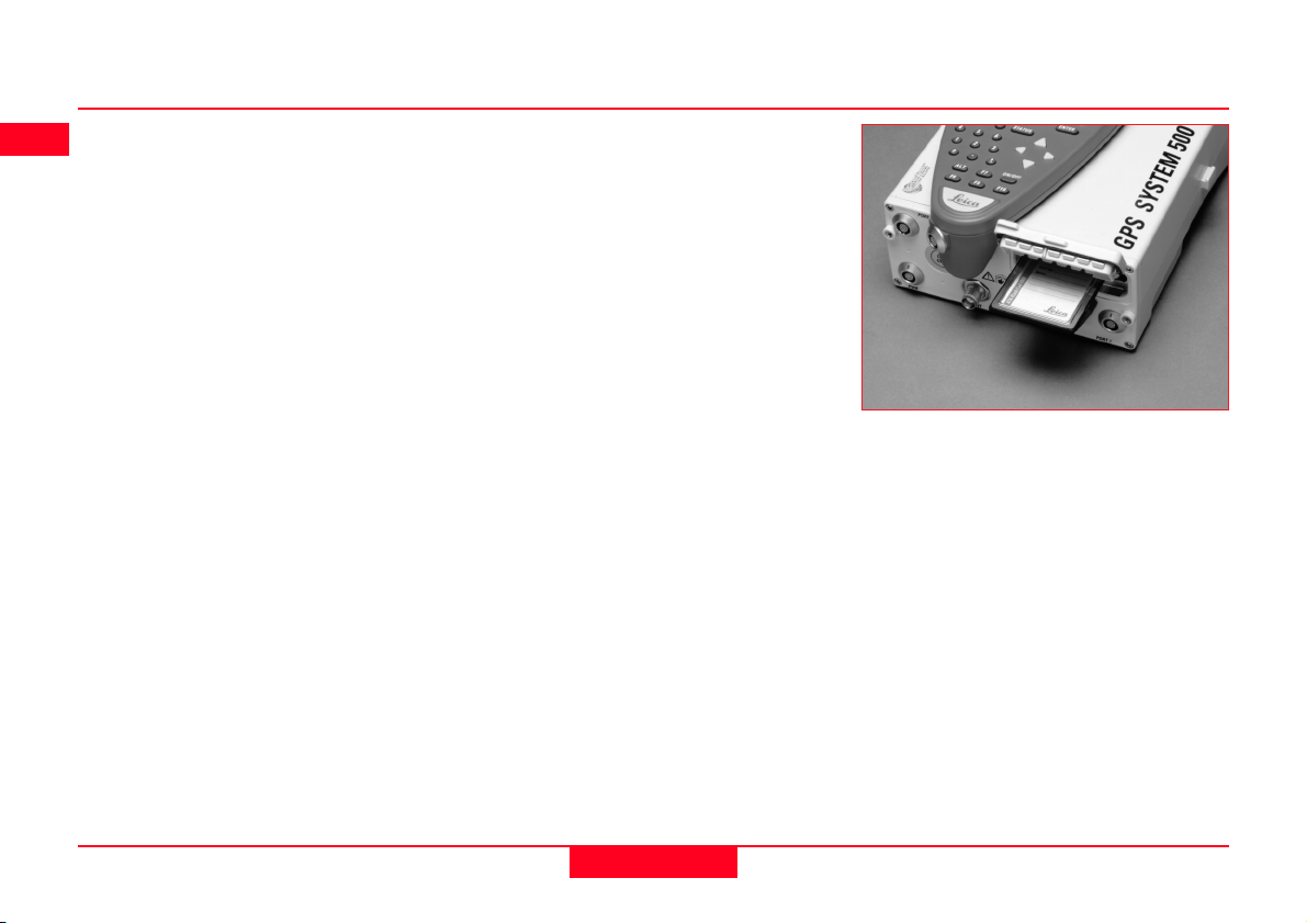
To insert the PC Card in the GPS
Receiver, open the card slot door,
with the Leica Logo uppermost and
facing you, slide the card into the slot
firmly until it clicks into position. Press
the eject button at the side of the card
to remove it.
The Internal Memory is available in
8MB or 16MB capacities and resides
in the Receiver. When data has to be
downloaded to SKI-Pro, connection is
made between port 2 on the Receiver
and a serial port on the PC.
The memory device is checked
before starting a survey. If it is more
than 80% full, an information message appears.
Follow the care instructions shown on
the rear of the card. Keep the card
dry, only use within the specified
temperature range, do not bend the
card and protect it from direct shock.
Failure to follow these instructions
could result in data loss and/or
permanent damage to the card.
The card can become very hot during
use. Avoid touching the metal parts of
the card after prolonged use.
Inserting the PC Card
1. Introduction
16
Technical Reference Manual-4.0.0en

PC Card versus Internal Memory
The PC Card is the preferred data
storage medium as it has the following advantages over internal memory:
• Faster download times. A PC
Card download using a PC
Card Reader or PCMCIA port is
virtually instantaneous. Internal
memory has to download
through a serial connection and
can take time.
• Flexibility / no downtime of
GPS Receiver. A PC Card can
be removed from a receiver
when it is full and replaced with
a spare. The Receiver does not
have to be taken back to the office
for downloading.
Using an Internal Memory means
however that the data has less
chance of being misplaced or lost.
This can happen when multiple PC
Cards are used for the same project.
If you are not sure about which type
of memory to use, try using a PC card
but don’t remove it from the Receiver.
You can still download as if it were
Internal Memory through any port.
Technical Reference Manual-4.0.0en
17
1. Introduction
1.5 Batteries/Power Supply
System 500 will normally be powered
by two GEB121 camcorder type
batteries. which plug into the underside of the GPS receiver.
Two batteries, fully charged, will
power the SR510 and TR500 for
about 7.5 hours continuously and the
SR520/530 for about 6 hours continuously.
Operating times will be shorter when
working in cold weather and when a
radio modem is connected.
Plug in and remove the GEB121
batteries as shown opposite.
System 500 can also be powered by
the GEB71 7Ah battery or any 12V
DC power supply via either power
port, on the front face of the receiver
using an appropriate cable.
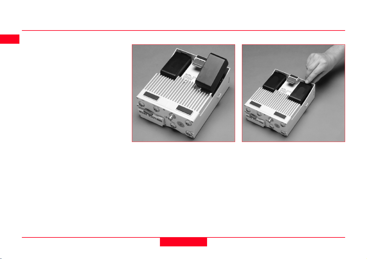
Connecting a GEB121 Battery
With the Receiver upside down and
the Leica logo on the battery facing
you, locate one end into the battery
bay. Press the opposite end of the
battery down until it audibly clicks into
place.
The battery contains toxic material and must be disposed of in an environmentally friendly manner. Do not dispose of the battery in normal household or
office waste.
Removing a GEB121 Battery
Pull and hold the battery catch.
Withdraw the battery with the other
hand.
1. Introduction
18
Technical Reference Manual-4.0.0en

1.5.1 Charging the Batteries
GEB121 Batteries
GEB121 Batteries can be charged
using the GKL122 or GKL111 battery
chargers. The preferred model is the
GKL122.
GEB71 Batteries
GEB71 Batteries can be charged
using the GKL122 battery charger
only.
Chargers
The GKL122 is an intelligent charger.
It will charge the batteries by the
exact amount required. This maximizes battery life. The GKL122 can
charge up to 2 GEB121 batteries at
once. The GDI121 extension plate
enables a further two batteries to be
charged from the same charger at the
same time.
Additionally, the GKL122 can charge
up to two GEB71 batteries.
The GKL111 battery charger is a
simple charger. It will charge one
GEB121 battery at a time. It will
charge the batteries by the exact
amount required. This maximizes
battery life.
The batteries are delivered
from the factory totally
discharged. They will require a full
charging cycle before the equipment
can be used. For full instructions on
battery charging, refer to the manual
accompanying the charger you are
using.
Technical Reference Manual-4.0.0en
19
1. Introduction

2. Equipment Set Up and Connection
The type of equipment set up that is
used will vary with the type of site
occupation and the measuring mode.
This also applies to the way in which
the various components are connected together. There are optimal
solutions for setting up the equipment
on a tripod, in a backpack and on the
pole.
Set up on Tripod
Set up on Unipole
2. Set-up and Connection
Set up on pole with Minipack
20
Technical Reference Manual-4.0.0en
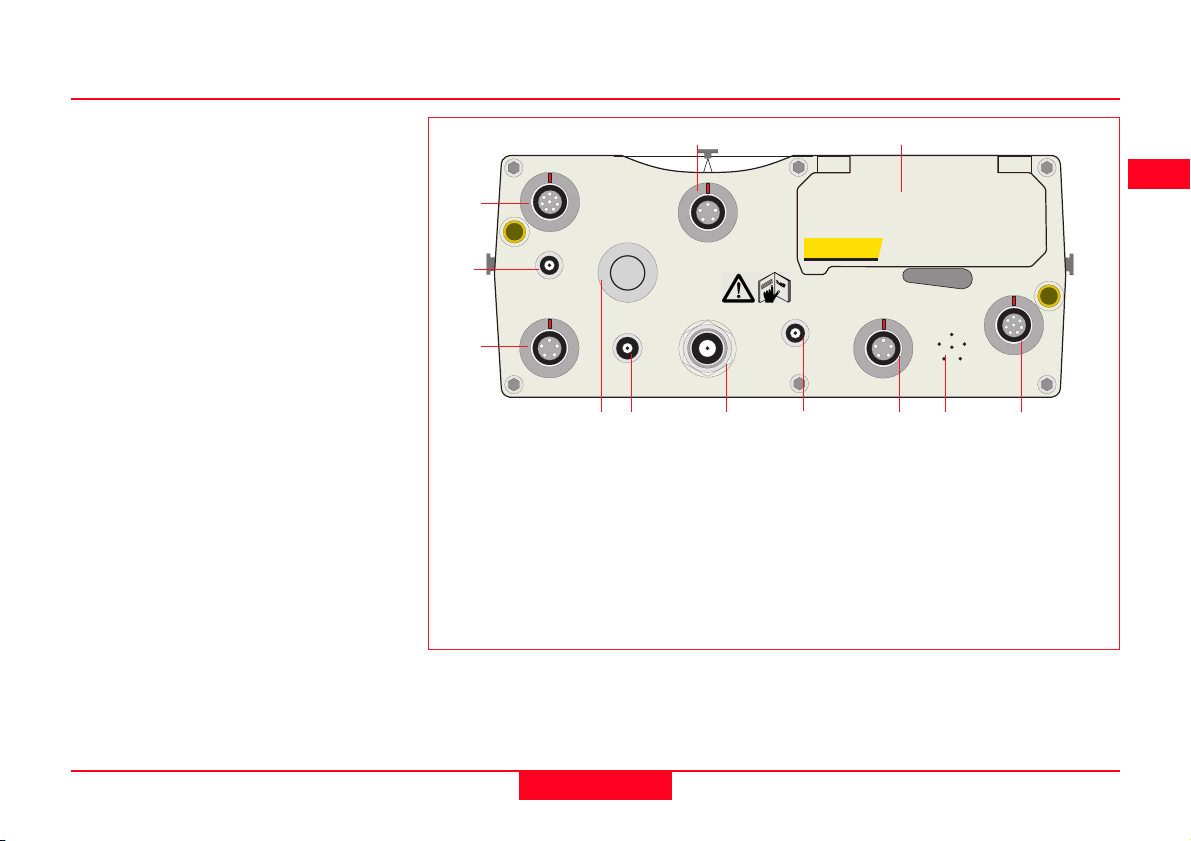
2.1 GPS Receiver ports
All other components of System 500
connect to the GPS Receiver.
The TR500 Terminal fits either
directly on the Receiver or can be
connected to the Terminal port using
a cable.
A Radio Modem in a housing can also
be fitted directly to the Receiver.
Alternatively, if the housing is not
being used, the radio modem can be
connected to Port 1 or Port 3 using a
cable.
The Antenna is connected to the
Receiver via the ANT Port.
External power can be connected via
a cable through Port 2.
12
PORT 3
1
2
EVENT1
ON
OFF
TERMINAL
3
PWR
PPS
46 8910
5
1. Port 3. 8 pin Lemo.Power/data
in/out
2. Event Input 1 (Optional)
3. 5 pin Lemo. Power
4. Power ON/OFF
5. PPS Output (Optional)
6. GPS Antenna in
7. Event Input 2 (Optional)
SR530 Receiver, front panel
11
LEICA SR530
EVENT2
PORT 1PORT 2/PWRANT
7
8. Port 2. 5 pin Lemo. Power/data
in/out.
9. Pressure equalisation vent.
10. Port 1. 8 pin Lemo. Power/data
in/out.
11. PC Card door.
12. Terminal in/out or Remote
Interface in/out.
Technical Reference Manual-4.0.0en
21
2. Set-up and Connection

2.2 Equipment Setup - Post Processed Static/Rapid Static/Reference on Pillar
Use
Static/Rapid Static operations or as Reference for Kinematic.
The Receiver and TR500 (if used) can be assembled to
make one unit. One connection is made to the GPS
Antenna which is mounted on the Pillar. The Receiver and
TR500 can be kept in the case. Note that the Receiver
can be programmed with the TR500 prior to use which
can then be omitted from the set up.
Assumptions
1. GPS Antenna is mounted directly using screw fitting.
If using stub and GAD 31 adapter, procedures may
vary slightly.
2. GPS Antennas are AT501 or AT502. Procedures/
setup may vary if AT503, 504 or single frequency
choke ring are used.
2. Set-up and Connection
22
Technical Reference Manual-4.0.0en

Equipment Checklist
1. GPS Antenna AT501, 502, 503,
504 or 505
2. GRT146 Carrier
3. GDF122 or GDF112 Tribrach
4. Pillar Plate (if required)
5. GEV120 2.8m Antenna Cable
6. 2, GEB121 Batteries
7. SR510/520/530 GPS Receiver
8. TR500 Terminal (if required)
9. MCF XMB-3 PC Flash Card.
10. GVP602 System 500 Transport
Case.
Technical Reference Manual-4.0.0en
23
2. Set-up and Connection
Procedure
1. If a pillar plate is being used,
locate it on the pillar.
2. Screw the tribrach to the pillar
plate or the pillar. Level the
tribrach.
3. Place and lock the GRT146
Carrier in the Tribrach.
4. Screw the Antenna onto the
Carrier.
5. Check that the Tribrach is still
level.
6. Connect the GPS Receiver to
the Antenna using the GEV120
Antenna cable.
7. Plug the GEB121 batteries into
the GPS Receiver.
8. Attach the TR500 Terminal to
the Receiver if required.
9. Insert the PCMCIA Flash Card
into the Receiver.
10. Switch on the system using the
ON/OFF button.
11. The Receiver can be placed in
the Transport Case for additional
protection.
The Next Steps
If the Receiver has been pre-programmed and the TR500 is not being
used, further guidance is available in
Chapter 3.
If the Receiver has been pre-programmed and the TR500 is being
used, further guidance is available in
Chapter 7.
If the Receiver requires programming
with the TR500, further guidance is
available in Chapter 5.
When Using the GAD31
adapter and GRT144 carrier,
ensure that the Antenna and GAD31
assembly slide down the full length of
the GRT144 stub. An incorrectly
mounted Antenna will have a direct
effect on your results.
In wet conditions the Re-
ceiver can be placed in the
transport case during use for extra
protection. Try to shut the case as
completely as possible.
If the Receiver is left in the
case during use in temperatures exceeding 25°C, the lid should
be left open. Refer to Appendix A for
operating and storage temperatures.
Use an external battery such
as GEB71 to extend the
operating time past 6 hours.
2. Set-up and Connection
24
Technical Reference Manual-4.0.0en

2.3 Equipment Setup - Post Processed Static/Rapid Static/Reference on Tripod
Use
Static/Rapid Static operations or as Reference for Kinematic.
The Receiver and TR500 (if used) can be assembled to
make one unit. This clips to the tripod leg or is placed in
the transport container. One connection is made to the
Antenna. Note that the Receiver can be programmed with
the TR500 prior to use which can then be omitted from the
set up.
Assumptions
1. GPS Antenna is mounted directly using screw fitting.
If using stub and GAD 31 adapter, procedures may
vary slightly.
2. GPS Antennas are AT501 or AT502. Procedures/
setup may vary if AT503, 504 or single frequency
choke ring are used.
Technical Reference Manual-4.0.0en
25
2. Set-up and Connection
Equipment Checklist
1. GPS Antenna AT501 or AT502
2. GRT146 Carrier
3. GDF122 or GDF112 Tribrach
4. GST20, GST05 or GST05L
Tripod
5. GZS4 Height Hook
6. GEV120 2.8m Antenna Cable
7. 2, GEB121 Batteries
8. SR510/520/530 GPS Receiver
9. TR500 Terminal (if required)
10.MCF XMB-3 PCMCIA Flash
Card.
11. GVP602 System 500 Transport
Case.
2. Set-up and Connection
26
Technical Reference Manual-4.0.0en
Procedure
1. Set up the tripod.
2. Mount and level the tribrach on
the tripod.
3. Place and lock the GRT146
Carrier in the Tribrach.
4. Screw the Antenna onto the
Carrier.
5. Check that the Tribrach is still
level.
5. Insert the Height Hook into the
Carrier.
6. Connect the GPS Receiver to
the Antenna using the GEV120
Antenna cable.
7. Plug the GEB121 batteries into
the GPS Receiver.
8. Attach the TR500 Terminal to
the Receiver if required.
9. Insert the PCMCIA Flash Card
into the Receiver.
10. Using the hook on the rear of
the unit, hang it on the Tripod leg
or place it in the box.
11. Switch on the system using the
ON/OFF button on the Receiver.
The Next Steps
If the Receiver has been pre-programmed and the TR500 is not being
used, further guidance is available in
Chapter 3.
If the Receiver has been pre-programmed and the TR500 is being
used, further guidance is available in
Chapter 7.
If the Receiver requires programming
with the TR500, further guidance is
available in Chapter 5.
When Using the GAD31
adapter and GRT144 carrier,
ensure that the Antenna and GAD31
assembly slide down the full length of
the GRT144 stub. An incorrectly
mounted Antenna will have a direct
effect on your results.
In wet conditions the Re-
ceiver can be placed in the
transport case during use for extra
protection. Try to shut the case as
completely as possible.
If the Receiver is left in the
case during use in temperatures exceeding 25°C, the lid should
be left open. Refer to Appendix A for
operating and storage temperatures.
Use an external battery such
as GEB71 to extend the
operating time past 6 hours.
Technical Reference Manual-4.0.0en
27
2. Set-up and Connection

2.4 Equipment Setup - Post Processed Kinematic, Minipack and Pole
Use
Post Processed Kinematic Rover.
The Receiver is placed in the Minipack. Connections are
made to the Antenna and TR500. Recommended for
extended periods of use in the field.
Assumptions
1. GPS Antenna is mounted directly using screw fitting.
If using stub and GAD 31 adapter, procedures may
vary slightly.
2. Aluminium poles are used. You may replace them
with their Carbon Fiber equivalents without any
change to these instructions.
2. Set-up and Connection
28
Technical Reference Manual-4.0.0en
Equipment Checklist
1. GPS Antenna AT501 or 502
2. GLS21 Upper half aluminium
pole with screw
3. GHT25 Grip for pole
4. GHT27 Holder for TR500
5. GLS20 Lower half aluminium
pole
6. GEV141 1.2m Antenna cable
7. GEV142 1.6m Antenna cable
8. TR500 Terminal
9. 2, GEB121 Batteries
10. SR510, 520 or 530 GPS Re-
ceiver
11. GVP603 Minipack
12. MCF XMB-3 PCMCIA flash card
13. GEV97 1.8m, 5pin Lemo cable
Technical Reference Manual-4.0.0en
29
2. Set-up and Connection
How to set up the equipment
1. Screw the two halves of the pole
together.
2. Slide the grip onto the pole.
Attach the TR500 holder and
tighten the screw.
3. Screw the GPS Antenna to the
top of the pole.
4. Slide the TR500 into the holder
until it clicks into place.
5. Insert the PC Card into the
Receiver and plug in the
GEB121 batteries.
6. Place the Receiver front panel
up in the Minipack with the
batteries facing outwards.
Fasten the strap around the
Receiver
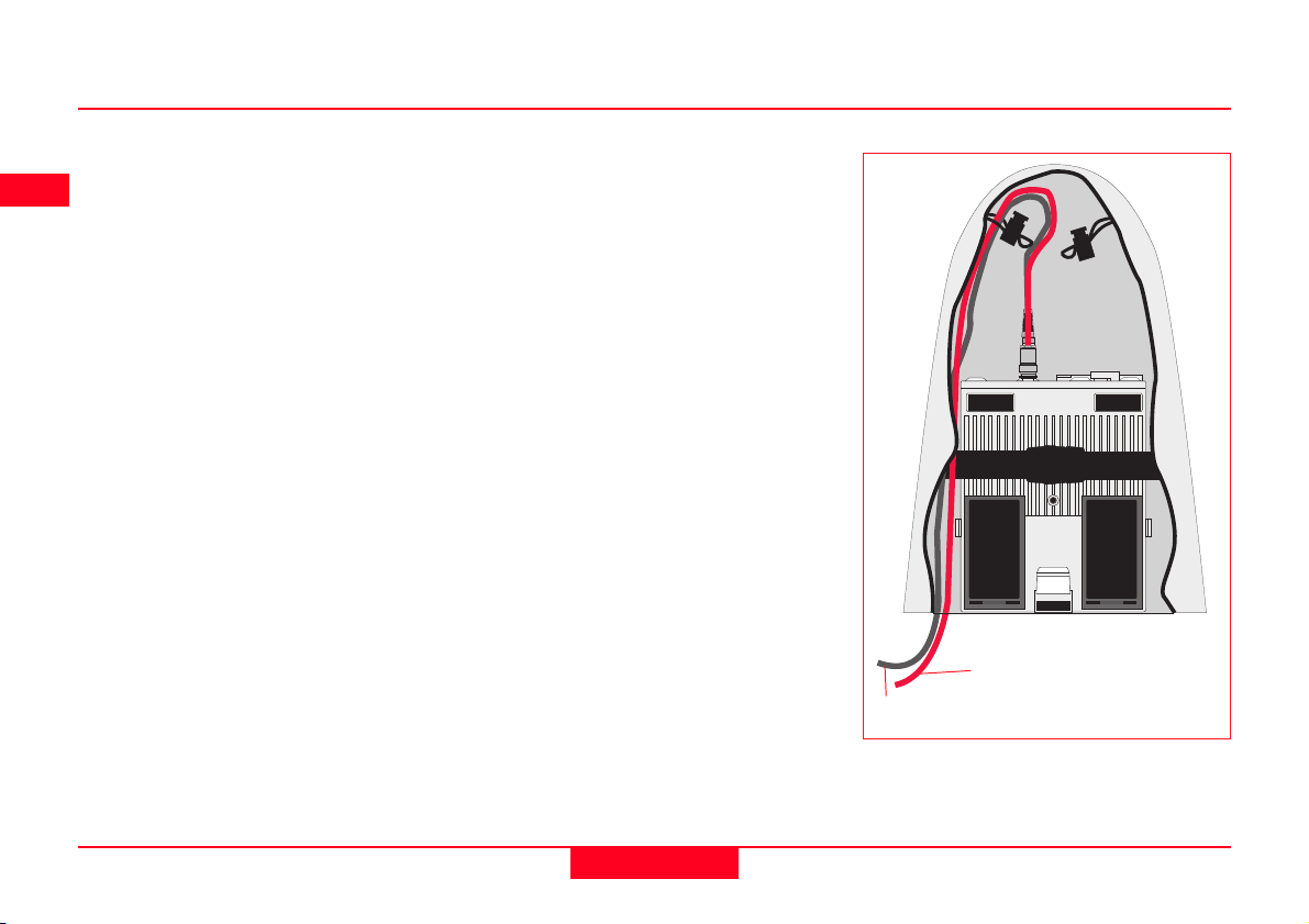
7. Connect the GPS Antenna to the
Receiver using the two Antenna
cables. Connect the longest
cable to the Receiver, pass the
cable through the cable brake
and down through the opening in
the bottom corner of the
Minipack flap. Draw the required
amount of cable out of the
Minipack and tighten the cable
brake. Refer to the diagram.
8. Connect the TR500 to the port
labelled “Terminal” on the
Receiver using the 1.8m cable.
Pass it through the opening in
the bottom of the Minipack flap,
down through a cable brake and
then plug into the Receiver.
Refer to the diagram.
10. Switch on the system using the
ON/OFF button on the Receiver.
To GPS Antenna
To Terminal
Connecting the TR500 Terminal and GPS
Antenna in the Minipack
2. Set-up and Connection
30
Technical Reference Manual-4.0.0en

The Next Steps
If the Receiver has been pre-programmed and the TR500 is being
used, further guidance is available in
Chapter 7.
If the Receiver requires programming
with the TR500, further guidance is
available in Chapter 5.
Ensure a dry plastic weather
protection cap is fitted to the
socket on the TR500 that is not
connected to the sensor.
If moisture or water should
appear in the socket that is
not used on the TR500, allow the
socket and plastic weather protection
cap to dry naturally.
When using the upper pole
halves with stub, ensure that
the Antenna and GAD31 screw/stub
adapter slide down the full length of
the stub before tightening the locking
ring. An incorrectly mounted Antenna
will have a direct effect on your
results.
Advice on using the Minipack
is given in Section 2.14.
Technical Reference Manual-4.0.0en
31
2. Set-up and Connection

2.5 Equipment Setup - Post Processed Kinematic, All on Pole, Direct Clip of TR500 on to Sensor
Use
Post-processed Kinematic Rover.
The TR500 is mounted on the Receiver which is screwed
onto the pole grip. One connection is made from the
Receiver to the Antenna. Recommended for short periods
of use, especially where there are many obstacles (fences
etc.).
Assumptions
1. GPS Antenna is mounted directly using screw fitting.
If using stub and GAD 31 adapter, procedures may
vary slightly.
2. Aluminium poles are used. You may replace them
with their Carbon Fiber equivalents without any
change to these instructions.
2. Set-up and Connection
32
Technical Reference Manual-4.0.0en

Equipment Checklist
1. GPS Antenna AT501 or 502
2. GLS18 Upper half aluminium
pole with screw
3. GHT25 Grip for pole
4. GHT26 Holder for GPS Receiver
5. GLS17 Lower half aluminium
pole
6. GEV141 1.2m Antenna cable
7. 2, GEB121 Batteries
8. TR500 Terminal
9. SR510, 520 or 530 GPS Re-
ceiver
10. MCF XMB-3 PCMCIA flash card
Technical Reference Manual-4.0.0en
33
2. Set-up and Connection

How to set up the equipment
1. Screw the two halves of the pole
together.
2. Slide the grip onto the pole.
Attach the GPS Receiver holder
and tighten the screw.
3. Screw the GPS Antenna onto
the top of the pole.
4. Attach the TR500 to the GPS
Receiver. Screw the GPS
Receiver to the GPS Receiver
holder.
5. Insert the PC Card into the
Receiver and plug in the
GEB121 batteries.
6. Connect the GPS Antenna to
the Receiver using the 1.2m
antenna cable.
7. Switch on the system using the
ON/OFF button on the TR500.
The Next Steps
If the Receiver has been pre-programmed and the TR500 is being
used, further guidance is available in
Chapter 7.
If the Receiver requires programming
with the TR500, further guidance is
available in Chapter 5.
When using the upper pole
halves with stub, ensure that
the Antenna and GAD31 screw/stub
adapter slide down the full length of
the stub before tightening the locking
ring. An incorrectly mounted Antenna
will have a direct effect on your
results.
2. Set-up and Connection
34
Technical Reference Manual-4.0.0en

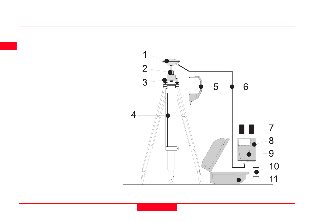
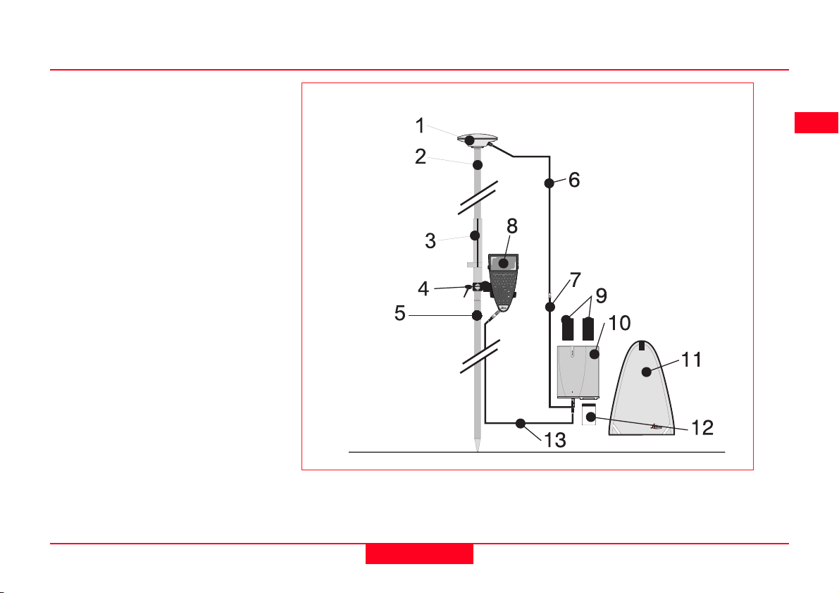
2.6 Equipment Setup - Post Processed Kinematic, All on Pole, TR500 and Sensor separated
Use
Post-processed Kinematic Rover.
The TR500 is fixed to the pole grip with a holder. With
another metallic holder and a holder piece, the receiver is
fixed to the pole. One connection is made from the Receiver to the Antenna. Another connection is made from
the Receiver to the TR500. Recommended for short
periods of use, especially where there are many obstacles
(fences etc.).
Assumptions
1. GPS Antenna is mounted directly using screw fitting.
If using stub and GAD 31 adapter, procedures may
vary slightly.
2. Aluminium poles are used. You may replace them
with their Carbon Fiber equivalents without any
change to these instructions.
Technical Reference Manual-4.0.0en
35
2. Set-up and Connection

Equipment Checklist
1. GPS Antenna AT501 or 502
2. GLS18 Upper half aluminium
pole with screw
3. GHT25 Grip for pole
4. GHT27 Holder for TR500
5. GLS17 Lower half aluminium
pole
6. GHT37 Holder piece for GPS
Receiver with antenna cable and
5pin Lemo cable
7. GHT26 Holder for GPS Receiver
8. TR500 Terminal
9. 2, GEB121 Batteries
10. SR510, 520 or 530 GPS Re-
ceiver
11. MCF XMB-3 PCMCIA flash card
5
1
2
4
8
3
9
L
10
11
2. Set-up and Connection
36
7
6
Technical Reference Manual-4.0.0en

How to set up the equipment
1. Screw the two halves of the pole
together.
2. Slide the grip onto the pole.
Attach the TR500 holder to the
grip and tighten the screw.
3. Slide the holder piece for the
GPS Receiver onto the pole.
Attach the GPS Receiver holder
and tighten the screw.
4. Screw the GPS Antenna onto
the top of the pole.
5. Slide the TR500 into the holder
until it clicks into place.
6. Screw the GPS Receiver to the
GPS Receiver holder.
7. Insert the PC Card into the
Receiver and plug in the
GEB121 batteries.
8. Connect the GPS Antenna to the
Receiver using the antenna
cable supplied with the GPS
receiver holder piece.
9. Connect the TR500 to the port
labelled “Terminal” on the
Receiver using the 5 pin Lemo
cable.
Technical Reference Manual-4.0.0en
10. Switch on the system using the
ON/OFF button on the TR500.
The Next Steps
If the Receiver has been pre-programmed and the TR500 is being
used, further guidance is available in
Chapter 7.
If the Receiver requires programming
with the TR500, further guidance is
available in Chapter 5.
37
When using the upper pole
halves with stub, ensure that
the Antenna and GAD31 screw/stub
adapter slide down the full length of
the stub before tightening the locking
ring. An incorrectly mounted Antenna
will have a direct effect on your
results.
2. Set-up and Connection

2.7 Equipment Setup - Real Time Reference, single tripod
Use
Real Time Reference Station. May also collect raw observation data for post-processing.
The Receiver and TR500 (if used) can be assembled to
make one unit. This clips to the tripod leg. Connections
are made to the GPS and Radio Antenna. Note that the
Receiver can be programmed with the TR500 prior to use
which can then be omitted from the set up.
The Radio Antenna is mounted on the Antenna Arm which
clips to the GPS Antenna.
The SR510 and SR520 can only be used as a DGPS
reference station if they are fitted with the DGPS option.
They cannot be used as a Real-Time Reference station.
The SR530 can be used as either a DGPS or Real-Time
reference station. Real-Time and DGPS are fitted as
standard on the SR530.
Assumptions
1. GPS Antenna is mounted directly using screw fitting.
If using stub and GAD 31 adapter, procedures may
vary slightly.
2. Standard Radio modem is used. (Mounted in Radio
Housing).
2. Set-up and Connection
38
Technical Reference Manual-4.0.0en

Equipment Checklist
1. GPS Antenna AT501, 502
2. GRT146 Carrier
3. GDF122 or GDF112 Tribrach
4. SR510/520/530 GPS Receiver
5. TR500 Terminal (if required)
6. GEV141 1.2m Antenna Cable
7. GST20/GST05/05L Tripod
8. GAT1/GAT2 Radio Antenna
9. GAD33 Radio Antenna Arm
10. GEV141 1.2m Antenna Cable
11. GZS4 Height Hook
12. Radio Modem in GFU 5/6
Housing
13. MCF XMB-3 PC card
14. 2, GEB121 Batteries
15. GVP602 Transport Case
Technical Reference Manual-4.0.0en
39
2. Set-up and Connection

How to set up the equipment
Follow steps 1-10 as described in
section 2.3.
11. Clip the Antenna Arm to the
GPS Antenna. Screw the Radio
Antenna onto the Arm.
12. Attach the Radio Modem in its
housing to the GPS Receiver.
13. Connect the Radio Antenna to
the Radio Modem using the
1.2m Antenna Cable.
14. Switch the System On using the
On/Off button on the Receiver.
The Next Steps
If the Receiver has been pre-programmed and the TR500 is not being
used, further guidance is available in
Chapter 3.
If the Receiver has been pre-programmed and the TR500 is being
used, further guidance is available in
Chapter 7.
If the Receiver requires programming
with the TR500, further guidance is
available in Chapter 5.
When Using the GAD31
adapter and GRT144 carrier,
ensure that the Antenna and GAD31
assembly slide down the full length of
the GRT144 stub. An incorrectly
mounted Antenna will have a direct
effect on your results.
In wet conditions the Re-
ceiver can be placed in the
transport case during use for extra
protection. Try to shut the case as
completely as possible.
If the Receiver is left in the
case during use in temperatures exceeding 25°C, the lid should
be left open. Refer to Appendix A for
operating and storage temperatures.
Use an external battery such
as GEB71 to extend the
operating time past 6 hours.
2. Set-up and Connection
40
Technical Reference Manual-4.0.0en

2.8 Equipment Setup - Real-Time Reference, Two Tripods
Use
The Receiver and TR500 (if used) can be assembled to
make one unit. This clips to the tripod leg. Connections
are made to the GPS and Radio Antenna. Note that the
Receiver can be programmed with the TR500 prior to use
which can then be omitted from the set up.
The Radio Antenna is mounted on the second tripod. This
increases the height of the Radio Antenna and therefore
maximizes radio coverage.
The SR510 and SR520 can only be used as a DGPS
reference station if they are fitted with the DGPS option.
They cannot be used as a Real-Time Reference station.
The SR530 can be used as either a DGPS or Real-Time
reference station. Real-Time and DGPS are fitted as
standard on the SR530.
Assumptions
1. GPS Antenna is mounted directly using screw fitting.
If using stub and GAD 31 adapter, procedures may
vary slightly.
2. Standard Radio modem is used. (Mounted in Radio
Housing).
Technical Reference Manual-4.0.0en
41
2. Set-up and Connection

Equipment Checklist
1. GPS Antenna AT501/502
2. GRT146 Carrier
3. GDF122 or GDF112 Tribrach
4. SR510/520/530 GPS Receiver
5. TR500 Terminal (if required)
6. GEV141 1.2m Antenna Cable
7. GST20\GST05\05L Tripod
8. GZS4 Height Hook
9. Radio Modem in GFU5/6
Housing
10. MCF XMB-3 PC Card
11. GEB121 Batteries
12. GST20\GST05\05L Tripod
13. GHT36 Base for Telescopic Rod
14. GEV120 2.8m Antenna Cable
15. GAT1\GAT2 Radio Antenna
16. GAD34 Short Antenna Arm
17. GAD32 Telescopic Rod
18. GVP602 Transport Case
15
16
1
2
3
14
17
13
8
4
5
6
7
9
10
11
12
18
2. Set-up and Connection
42
Technical Reference Manual-4.0.0en

How to set up the equipment
Follow steps 1-10 as described in
section 2.3.
11. Attach the Radio Modem in its
housing to the GPS Receiver.
12. Set up the second Tripod
nearby. Screw the Base onto the
Tripod. Push the Telescopic Rod
into the Base.
13. Screw the Short Antenna Arm
onto the telescopic Rod. Screw
the Radio Antenna onto the Arm.
14. Connect the Radio modem to
the Radio Antenna using the
2.8m Antenna cable.
15. Switch the System On using the
On/Off button on the Receiver or
Terminal.
The Next Steps
If the Receiver has been pre-programmed and the TR500 is not being
used, further guidance is available in
Chapter 3.
If the Receiver has been pre-programmed and the TR500 is being
used, further guidance is available in
Chapter 7.
If the Receiver requires programming
with the TR500, further guidance is
available in Chapter 5.
When Using the GAD31
adapter and GRT144 carrier,
ensure that the Antenna and GAD31
assembly slide down the full length of
the GRT144 stub. An incorrectly
mounted Antenna will have a direct
effect on your results.
In wet conditions the Re-
ceiver can be placed in the
transport case during use for extra
protection. Try to shut the case as
completely as possible.
If the Receiver is left in the
case during use in temperatures exceeding 25°C, the lid should
be left open. Refer to Appendix A for
operating and storage.
Technical Reference Manual-4.0.0en
43
2. Set-up and Connection

2.9 Equipment Setup - Real-Time Rover, Pole and Minipack
Use
The Radio Modem attaches to the Receiver and is placed
in the Minipack. Connections are made to the GPS
Antenna, Radio Antenna and TR500. Recommended for
extended periods of use in the field.
The cables coming from the Minipack can be disconnected in the event that an obstacle (E.g. a fence) has to
be crossed.
Assumptions
1. GPS Antenna is mounted directly using screw fitting.
If using stub and GAD 31 adapter, procedures may
vary slightly.
2. Aluminium poles are used. You may replace them
with their Carbon Fiber equivalents without any
change to these instructions.
2. Set-up and Connection
44
Technical Reference Manual-4.0.0en
Equipment Checklist
1. GPS Antenna AT501 or 502
2. GLS21 Upper half aluminium
pole with screw or stub
3. GHT25 Grip for pole
4. GHT27 Holder for TR500
5. GLS20 Lower half aluminium
pole
6. GEV141 1.2m Antenna cable
7. GEV142 1.6m Antenna cable
8. TR500 Terminal
9. 2, GEB121 Batteries
10. SR510, 520 or 530 GPS Re-
ceiver
11. Radio Modem in GFU5/6 Hous-
ing
12. MCF XMB-3 PCMCIA flash card
13. GEV97 1.8m, 5pin Lemo cable
14. GEV141 1.2m Antenna cable
15. GAT1/GAT2 Radio Antenna
16. GAD34 Small Antenna Arm
17. GAD32 Telescopic Rod
18. GVP603 Minipack
Technical Reference Manual-4.0.0en
45
2. Set-up and Connection
How to set up the equipment
Follow steps 1-5 as described in
section 2.4.
6. Attach the Radio Modem Hous-
ing containing the Radio Modem
to the GPS Receiver.
7. Place the GPS Receiver front
panel up in the Minipack with the
batteries facing outwards.
Fasten the strap around the
Receiver (refer to diagram)
8. Push the Telescopic Rod
through the slit in the top of the
Minipack. Ensure it is located in
the sleeve inside the Minipack
and push it all the way to the
bottom. Adjust the height of the
Telescopic Rod to suit.
9. Screw the Short Antenna Arm
onto the Telescopic Rod. Screw
the Radio Antenna onto the
Short Antenna Arm.
10. Connect the Radio Modem to
the Radio Antenna using a 1.2m
Antenna Cable. The cable
should pass down underneath
the Receiver and then up through
the slit in the top of the Minipack.
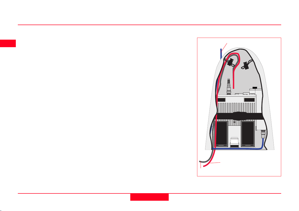
11. Connect the GPS Antenna to the
Receiver using the two Antenna
Cables. The longest Cable
should be connected to the
Receiver. Pass this cable
through a cable brake and down
through the slit under one of the
reflective strips at the bottom of
the Minipack. Draw the required
amount of cable out of the
Minipack and tighten the cable
brake. Refer to the diagram.
12. Connect the TR500 to the port
labelled “Terminal”on the Receiver using the 1.8m
cable.Pass it through the opening under one of the reflective
strips at the bottom of the
Minipack, up through a cable
brake and then plug into the
Receiver. Refer to the diagram.
13. Switch the System ON using the
ON/OFF key on the Terminal.
To Radio Antenna
To GPS Antenna
To Terminal
2. Set-up and Connection
46
Technical Reference Manual-4.0.0en
The Next Steps
If the Receiver has been pre-programmed and the TR500 is being
used, further guidance is available in
Chapter 7.
If the Receiver requires programming
with the TR500, further guidance is
available in Chapter 5.
Ensure a dry plastic weather
protection cap is fitted to the
socket on the TR500 that is not
connected to the sensor.
If moisture or water should
appear in the socket that is
not used on the TR500, allow the
socket and plastic weather protection
cap to dry naturally.
When using the upper pole
halves with stub, ensure that
the Antenna and GAD31 screw/stub
adapter slide down the full length of
the stub before tightening the locking
ring. An incorrectly mounted Antenna
will have a direct effect on your
results.
Advice on using the Minipack
is given in Section 2.14.
Technical Reference Manual-4.0.0en
47
2. Set-up and Connection

2.10 Equipment Setup - Real-Time Rover, All on Pole, direct clip of TR500 on to Sensor
Use
The TR500 is mounted on the Receiver which is clipped
to the grip. Connections are made from the Receiver to
the GPS and Radio Antennas. Recommended for short
periods of use, especially where there are many obstacles
(fences etc.).
Assumptions
1. GPS Antenna is mounted directly using screw fitting.
If using stub and GAD 31 adapter, procedures may
vary slightly.
2. Aluminium poles are used. You may replace them
with their Carbon Fiber equivalents without any
change to these instructions.
2. Set-up and Connection
48
Technical Reference Manual-4.0.0en

Equipment Checklist
1. GPS Antenna AT501 or 502
2. GLS21 Upper half aluminium
pole with screw or stub
3. GHT25 Grip for pole
4. GHT27 Holder for GPS Receiver
5. GLS17 Lower half aluminium
pole
6. GAT1/GAT2 Radio Antenna
7. GAD33 Antenna Arm
8. GEV141 1.2m Antenna Cable
9. 2, GEB121 Batteries
10. TR500 Terminal
11. SR510/520/530 GPS Receiver
12. Radio Modem in GFU5/6 Hous-
ing
13. MCF XMB-3 PC Card
14. GEV141 1.2m Antenna Cable
Technical Reference Manual-4.0.0en
49
2. Set-up and Connection

How to set up the equipment
Follow steps 1-6 described in section
2.5.
7. Clip the Antenna Arm to the
GPS Antenna. Screw the Radio
Antenna onto the Arm.
8. Attach the Radio Modem in its
housing to the GPS Receiver.
9. Connect the Radio Antenna to
the Radio Modem using a 1.2m
Antenna Cable.
10. Switch the System ON using the
ON/OFF key on the Terminal.
The Next Steps
If the Receiver has been pre-programmed and the TR500 is being
used, further guidance is available in
Chapter 7.
If the Receiver requires programming
with the TR500, further guidance is
available in Chapter 5.
When using the upper pole
halves with stub, ensure that
the Antenna and GAD31 screw/stub
adapter slide down the full length of
the stub before tightening the locking
ring. An incorrectly mounted Antenna
will have a direct effect on your
results.
The Radio Antenna may also
be connected directly to the
Radio Housing. Note however that
range and quality of signal received
may be affected.
2. Set-up and Connection
50
Technical Reference Manual-4.0.0en

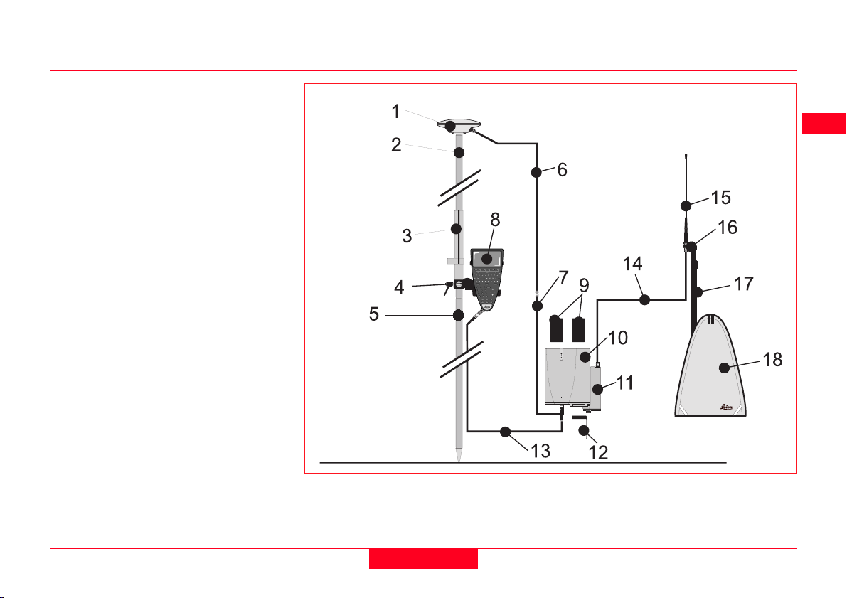
2.11 Equipment Setup - Real-Time Rover, All on Pole, TR500 and Sensor separated
Use
The TR500 is fixed to the pole grip with a holder. With
another metallic holder and a holder piece, the receiver is
fixed to the pole. The Radio Modem plus radio antenna
attaches to the Receiver. One connection is made from
the Receiver to the Antenna. Another connection is made
from the Receiver to the TR500. Recommended for short
periods of use, especially where there are many obstacles
(fences etc.).
Assumptions
1. GPS Antenna is mounted directly using screw fitting.
If using stub and GAD 31 adapter, procedures may
vary slightly.
2. Aluminium poles are used. You may replace them
with their Carbon Fiber equivalents without any
change to these instructions.
Technical Reference Manual-4.0.0en
51
2. Set-up and Connection

Equipment Checklist
1. GPS Antenna AT501 or 502
2. GLS18 Upper half aluminium
pole with screw
3. GHT25 Grip for pole
4. GHT27 Holder for TR500
5. GLS17 Lower half aluminium
pole
6. GHT37 Holder piece for GPS
Receiver with antenna cable and
5pin Lemo cable
7. GHT26 Holder for GPS Receiver
8. TR500 Terminal
9. 2, GEB121 Batteries
10. SR510, 520 or 530 GPS Re-
ceiver
11. GAT1/GAT2 Radio Antenna
12. Radio Modem in GFU5/6 Hous-
ing
13. MCF XMB-3 PCMCIA flash card
5
1
2
4
7
3
8
9
11
L
10
12
13
6
2. Set-up and Connection
52
Technical Reference Manual-4.0.0en

How to set up the equipment
Follow steps 1-9 described in section
2.6.
10. Attach the Radio Modem in its
housing to the GPS Receiver.
11. Screw the Radio Antenna onto
the housing.
12. Switch on the system using the
ON/OFF button on the TR500.
The Next Steps
If the Receiver has been pre-programmed and the TR500 is being
used, further guidance is available in
Chapter 7.
If the Receiver requires programming
with the TR500, further guidance is
available in Chapter 5.
When using the upper pole
halves with stub, ensure that
the Antenna and GAD31 screw/stub
adapter slide down the full length of
the stub before tightening the locking
ring. An incorrectly mounted Antenna
will have a direct effect on your
results.
Technical Reference Manual-4.0.0en
53
2. Set-up and Connection

2.12 Equipment Setup - Real Time Rover, GIS Rover
Use
The TR500 is held in the hand with the hand pouch.
Connections are made from the Receiver to the GPS (or if
being used the combined GPS/DGPS antenna). Recommended for long periods of use, for mainly GIS type data
collection surveys.
The setup described in the following pages assumes an
RTB or RTS module is being used (see also Appendix K
for further information on GIS applications).
You may also use the Real-Time GIS Rover setup with a
standard radio device but note the following differences:
1. With a standard radio device being used you will need a
separate radio antenna: attach the GAT1/GAT2 Radio
Antenna to the pole using the GAD33 Antenna Arm (see
the RT-Rover, All on Pole chapter for further illustration).
2. The RTB/ RTS module cable will not be needed then:
Connect the Radio antenna to the Radio modem housing
using the GEV141 1.2m Antenna Cable (see the RTRover, Pole and Minipack chapter for further illustration).
2. Set-up and Connection
54
Technical Reference Manual-4.0.0en

Equipment Checklist
1. Combined RTB (or RTS)/GPS
antenna
2. GAD32 Telescopic Rod
3. GEV141 1.2m Antenna Cable
4. RTB (or RTS) differential
receiver module
5. 0.3m GPS receiver to RTB (or
RTS) module cable
6. MCF XMB-3 PC Card
7. GEV97 1.8m, 5pin Lemo cable
8. TR500 Terminal
9. 2, GEB121 Batteries
10. GS50 GPS Receiver
11. Handstrap with beltclip for
TR500 Terminal
12. GVP603 Minipack
1
2
8
11
7
10
L
3
9
12
4
5
6
L
Technical Reference Manual-4.0.0en
55
2. Set-up and Connection

How to set up the equipment
1. Insert the PC Card into the
Receiver and plug in the
GEB121 batteries.
2. Place the Receiver front panel
up in the Minipack with the
batteries facing outwards.
Fasten the strap around the
Receiver
3. Connect the RTB/GPS Antenna
to the Receiver using the Antenna cables. Connect the cable
to the RTB/RTS module and
route the cable around the
bottom of the Receiver and up to
to the GPS antenna. Refer to the
diagram.
4. Connect the TR500 to the port
labelled “Terminal” on the
Receiver using the 1.8m cable.
Pass it through the opening in
the bottom of the Minipack flap,
down through a cable brake and
then plug into the Receiver.
Refer to the diagram.
5. Connect the RTB/RTS module to
the Receiver GPS antenna port
using the 30 cm antenna cable.
6. Switch on the system using the
ON/OFF button on the Receiver.
To GPS/RTB (or RTS) antenna
From RTS/RTB module
To Terminal
to GPS antenna port
2. Set-up and Connection
56
Technical Reference Manual-4.0.0en

The Next Steps
If the Receiver has been pre-programmed and the TR500 is being
used, further guidance is available in
Chapter 7.
If the Receiver requires programming
with the TR500, further guidance is
available in Chapter 5.
Ensure a dry plastic
weather protection cap is
fitted to the socket on the TR500 that
is not connected to the sensor.
If moisture or water should
appear in the socket that is
not used on the TR500, allow the
socket and plastic weather protection
cap to dry naturally.
Advice on using the
Minipack is given in Section
2.14.
Technical Reference Manual-4.0.0en
57
2. Set-up and Connection

2.13 Equipment Setup - Repeater Station and Repeater Box
Use
The repeater box attaches to a tripod and the radio modem
to the repeater box. An external battery also attaches to the
tripod. The Radio Antenna is mounted on the tripod. One
connection is made from the battery to the repeater box.
Another connection is made from the radio to the radio
antenna.
For more information on repeaters and the repeater box see
Appendix H.
Assumptions
1. A RTK reference is set up, pre-programmed according
to chapter 5.3 and running according to chapter 7.3.
2. A RTK rover is prepared and pre-programmed
according to chapter 5.4.
3. The same type of radios are used on reference,
repeater and rover station.
4. The radio modem at the repeater station is
programmed to repeater mode.
5. All radio modems at reference, repeater and rover
operate on the same frequency.
6. The reference and rover receivers run standard
firmware 3.00 or higher.
2. Set-up and Connection
58
Technical Reference Manual-4.0.0en

Equipment Checklist
1. GAT1\GAT2 Radio Antenna
2. GAD34 Short Antenna Arm
3. GAD32 Telescopic Rod
4. GHT36 Base for Telescopic Rod
5. GEV120 2.8m Antenna Cable
6. Radio Modem in GFU5/6
Housing
7. GHT38 Repeater Box
8. 1.8 m Connection cable for
external battery
9. GEB71 Battery
10. GST20\GST05\05L Tripod
1
2
5
6
7
8
3
4
9
10
Technical Reference Manual-4.0.0en
59
2. Set-up and Connection

How to set up the equipment
1. Set up the tripod.
2. Screw the Base for the
Telescopic Rod onto the Tripod.
Push the Telescopic Rod into
the Base.
3. Screw the Short Antenna Arm
onto the Telescopic Rod. Screw
the Radio Antenna onto the Arm.
4. Connect the Radio Modem to
the Repeater Box. Attach the
Repeater Box to the tripod.
5. Connect the Radio Modem to the
Radio Antenna using the 2.8m
Antenna Cable.
6. Connect the Repeater Box to the
GEB71 battery.
The Next Steps
As soon as the Repeater Box is
connected to the battery, it is ready to
receive and broadcast data.
Start surveying or a staking-out with
the rover. Further guidance is
available in Chapter 7.4 and 7.5.
2. Set-up and Connection
60
Technical Reference Manual-4.0.0en

2.14 Using the Minipack
The Minipack has several features
which may not be readily apparent at
first. These features help to make
using System 500 more comfortable.
1. Antenna Pole Strap
Ensures the Antenna Pole does not
sway around and remains as upright
as possible.
Pass the strap around the pole and
fasten using the clip as shown in the
photograph.
2. Hip Belt
The Hip Belt transfers most of the
weight from the shoulders to the hips
when properly adjusted.
It also contains velcro attachments
through which cables can be passed.
Use the attachments as shown in the
photograph.
Technical Reference Manual-4.0.0en
61
2. Set-up and Connection

3. Internal Net Pouch
The Backpack has an internal net
pouch designed for carrying an
AT501 or AT502 Antenna when not in
use. It can also be used for storing
coiled cables or carrying a nonstandard radio modem.
4. Using the Minipack in high
temperatures
In high temperatures it is desirable to
increase air flow around the Receiver.
Therefore the backpack can be kept
half or even fully open when in use.
Open the Minipack halfway. Tuck the
flap inside. Secure it with the velcro
pad.
Open the Minipack flap fully and fold
the flap under the Receiver during
use in extremely hot temperatures.
2. Set-up and Connection
62
Technical Reference Manual-4.0.0en

2.15 Measuring Antenna Heights
The height of the GPS Antenna above the point consists
of several components - the Height Reading, the Vertical
Offset and the Phase Center Eccentricities. When a
standard System 500 Antenna mounted on standard
System 500 accessories is selected, the only measurement you will have to input is the Vertical Height (shown
as VR in the following section). When a pole is used, even
this value is automatically suggested by the Receiver as
2.00m (the height of the System 500 pole).
This means that for most operations, you will only need to
input the height measurement from the height hook or use
the default height measurement of 2.00m for the pole.
However, there may be cases when you need to calculate
the height components, such as when using non-Leica
accessories or Antennas or when not using a tripod or
pole.
It is also important to realize where the Antenna Heights
are measured to. This Datum is referred to as the Mechanical Reference Plane. This varies for different Antennas. It is also the datum from which the Phase Center
Eccentricities are calculated.
Phase Center Eccentricities of Leica Antennas are
handled automatically by System 500. They will have to be
entered manually when using non-Leica Antennas. Advice
on how to create a new Antenna Type for non-Leica
Antennas is given in the Online Help of SKI-Pro (Antenna
Management).
Finally, the Antenna Height is sometimes calculated by
taking a slope distance from the point on the ground to the
outside edge of the Antenna. In this case, the Vertical
Height must be calculated using the Slope Height and a
Horizontal Offset.
Special care must be taken when using System 300 GPS
Antennas with a System 500 Receiver or when using the
AT501/502 GPS Antenna on the System 300 pole.
Technical Reference Manual-4.0.0en
63
2. Set-up and Connection

2.15.1 Mechanical Reference Planes
The Mechanical Reference Plane or datum to which the
Antenna Height is measured and from which the Phase
Center Eccentricities are calculated is shown for each
Leica System 500 Antenna.
AT501 and AT502
MRP
The Mechanical Reference Plane is the underside of the
threaded metal insert.
AT503
MRP
0.1501m
AT504
0.1897m
0.0345m
MRP
The Mechanical Reference Plane is the underside of the
Preamplifier Housing. The AT504 is built to a JPL design
specified by the IGS for Reference Stations. The Mechanical Reference Plane is always referred to as the
Bottom of Preamplifier or BPA by the IGS.
The Mechanical Reference Plane is the underside of the
Antenna itself.
2. Set-up and Connection
64
Technical Reference Manual-4.0.0en

2.15.2 Antenna Height components
1. Pillar Setup
MRP
VE1
VE2
VO=0
VO Vertical Offset
VR Vertical Height Reading
VE1 Vertical Phase Center Eccentricity for L1.
VE2 Vertical Phase Center Eccentricity for L2
MRP Mechanical Reference Plane
Although an AT501/502 Antenna is shown, the same principles apply to the
AT504 and AT303.
VR
Technical Reference Manual-4.0.0en
The Vertical Height (VR) value is measured from the pillar benchmark to the
Mechanical Reference Plane of the Antenna. As there is no accessory available to measure the Vertical Height in this case, it is usually obtained through
levelling. Refer to the details on the next page for help in measuring the
Vertical Height.
The Vertical Offset is not required in this case and therefore is input as zero.
The Vertical Phase Center Eccentricities are stored in the Receiver for all
Leica System 500 Antennas and any non-Leica Antenna that you define. As
long as the correct antenna is chosen there is no need to enter any value into
the Receiver. These values do need to be calculated when a new type of
Antenna that does not exist in the Antenna Setup Records is used.
65
2. Set-up and Connection

Pillar Setup II - Carrier and Adapter dimensions
9.399.7
109
All dimensions are shown in millimeters and may be required when
determining the Vertical Height
Reading on a pillar or other nonstandard setup. They allow you to determine the height to a surface on the
carrier (which is probably easier than
determining it to the Mechanical
Reference Plane), and then add the
remaining value to the Mechanical
Reference Plane.
145.5
36.5
GRT44 Carrier with GAD31 Stub to
Screw Adapter
2. Set-up and Connection
145.5
36.5
GRT46 Carrier
66
Technical Reference Manual-4.0.0en

2. Tripod Setup
MRP
VE1
VO Vertical Offset
VR Vertical Height Reading
VE1 Vertical Phase Center Eccentricity for L1.
VE2 Vertical Phase Center Eccentricity for L2
MRP Mechanical Reference Plane
VE2
Although an AT501/502 Antenna is shown, the same principles apply to the
AT504 and AT303.
VO
The Vertical Height Reading (VR) value is measured using the Height Hook.
The Vertical Offset (VO) value is stored in the Antenna Setup record and for a
Tripod Setup with the Height Hook as shown is 0.36m. This will need to be
measured if you are entering a new Antenna Setup Record without using the
Height Hook. There are two methods for mounting Leica Antennas - using a
GRT46 with a 5/8 inch screw or using a GRT44 with stub and a GAD31 stub to
VR
screw adapter. The VO value remains constant whichever setup is used.
The Vertical Phase Center Eccentricities are stored in the Receiver for all
Leica System 500 Antennas and any non-Leica Antenna that you define. As
long as the correct antenna is chosen there is no need to enter any value into
the Receiver. These values do need to be calculated when a new type of
Antenna that does not exist in the Antenna Setup Records is used.
Technical Reference Manual-4.0.0en
67
2. Set-up and Connection

3. Pole Setup
MRP
VE1
VE2
VR
VO = 0
VO Vertical Offset
VR Vertical Height Reading
VE1 Vertical Phase Center Eccentricity for L1.
VE2 Vertical Phase Center Eccentricity for L2
MRP Mechanical Reference Plane
Although an AT501/502 Antenna is shown, the same principles apply to the
AT504 and AT303.
The Vertical Height Reading (VR) value fixed at the height of the pole. With a
standard Leica System 500 pole this is 2.0m. There are two System 500 upper
pole halves. One has a 5/8 inch screw - the Antenna screws on directly. The
other has a stub and uses a GAD31 stub to screw adapter. Whichever pole
type is used, the height remains at 2.00m. Additional 1.00 m pole sections
maybe easily added or subtracted. In some special cases where the lower half
of the pole alone is used, the height will be 1.00m.
The Vertical Offset (VO) value is zero in this case.
The Vertical Phase Center Eccentricities are stored in the Receiver for all
Leica System 500 Antennas and any non-Leica Antenna that you define. As
long as the correct Antenna is chosen there is no need to enter any value into
the Receiver. These values do need to be calculated when a new type of
Antenna that does not exist in the Antenna Setup Records is used.
2. Set-up and Connection
68
Technical Reference Manual-4.0.0en

2.15.3 Measuring Slope Heights
VE2
VE1
-VO
HO
MRP
VO Vertical Offset
HO Horizontal Offset
SR Slope Height Reading
VE1 Vertical Phase Center Eccentricity for L1.
VE2 Vertical Phase Center Eccentricity for L2
MRP Mechanical Reference Plane
If you are using the Slope Height Reading the antenna
height is calculated as follows:
Technical Reference Manual-4.0.0en
SR
Antenna Height =
√(√(
√(SR² - HO²) ± VO
√(√(
If the Offset Point on the antenna is above the Mechanical
Reference Plane MRP, the Vertical Offset VO is negative.
The Slope Height Reading is measured from the point on
the ground to the outside edge of the antenna. The
Antenna used for this example is a Dorne Margolin T
(Leica AT504) as specified by the IGS. The Mechanical
Reference Plane will differ depending on the Antenna type
used.
69
2. Set-up and Connection

3. Using System 500 without a Terminal
The SR510, 520 and 530 receivers
can be used without the TR500
attached.
Applications and set ups most suited
to this type of configuration are
Reference Stations for Post-Processing and Real-Time and Static/Rapid
Static measurements.
The receiver can be programmed in
the office using the TR500. This
greatly reduces the knowledge
required to operate the instrument in
the field.
Full instructions on how to program
the receiver are given in Chapter 5.
703. Using System 500 without a Terminal
Technical Reference Manual-4.0.0en

3.1 Setting up the Equipment
3.2 Operation 3.3 Shut Down
The Receiver and Antenna will
usually be mounted on a tripod or
pillar. Refer to Chapter 2 for details
of equipment set up and connections.
Measure the Antenna Height using
the Height Hook. Note this value
down. You will need to enter it into
SKI-Pro when you get back to the
office. You should also note the Point
Id and start and stop times.
A suggested form for recording
necessary data is given in section
3.5.
The Receiver needs to be configured
correctly before it will work. The
parameters that are especially
important for working without a
Terminal are in Occupation Settings.
Full details are given in Chapter 5.
Once the equipment is set up, switch
it on using the ON/OFF switch on the
Receiver.
The equipment will automatically
begin to acquire and track satellites
and record data as set up in the
Receiver configuration.
Wait at the point for the required time.
Note that the required observation
time does not begin until the Satellite
Status LED is constant green (see
next section). A list of approximate
observation times for Rapid Static
and Static baseline measurements is
given in Appendix B.
To shut down the equipment press
and hold the ON/OFF button for 3
seconds. The LED indicators will not
be lit when the equipment is switched
off.
Technical Reference Manual-4.0.0en
71
3. Using System 500 without a Terminal

3.4 LED Indicators
3.4.1 Power LED 3.4.2 Satellite Status LED
Every System 500 Receiver has three
LED indicators that inform the operator of basic Receiver status. The LED
indicators are located at the top of the
Receiver and are only visible when
the TR500 Terminal is not attached.
The top LED gives power information,
the middle gives satellite tracking
information and the lower gives
memory status.
Power
Satellite Tracking
Memory Status
Power LED off No Power
Power LED
green - Power
OK
Power LED
Flashing Green Power Low
Satellite Status
LED off - No
Satellites tracked
Satellite Status
LED flashing
green - first
satellite tracked,
position not yet
available
Satellite Status
LED Green Enough satellites
tracked to compute position
723. Using System 500 without a Terminal
Technical Reference Manual-4.0.0en

3.4.3 Memory Status LED
3.5 Field Record Sheet
Memory Status
LED off - Memory
Device not
available (PC
Card not inserted
or Internal
Memory not
fitted).
Memory Status
LED Green Memory capacity
OK on selected
device
Memory Status
LED flashing
green - Memory
capacity 75% full
on selected
device
Memory Status
LED red Memory full on
selected device
Field Record - Static/Rapid
Static Survey point
Operator Name:
Start time (Local):
Stop Time (Local):
Point ID:
Antenna Height:
Receiver Serial No.:
Date:
Technical Reference Manual-4.0.0en
73
3. Using System 500 without a Terminal

4. TR500 Terminal Overview
The TR500 Terminal performs three main functions:
1. Program the GPS Receiver
2. Enable input of information to the GPS Receiver
3. Display information from the GPS Receiver
The Terminal must be connected to the GPS Receiver to function. It can be
connected using a cable or mounted directly onto the receiver.
Once connected, the Terminal and Receiver can be switched on using the ON/
OFF key on the Terminal.
A GHT28 handstrap/beltclip is available which fits on the rear of the Terminal.
This improves handling of the Terminal in applications where it is held constantly in the hand. (E.g. GIS applications).
TR500 Terminal attached to GPS Receiver
with cable
4. TR500 Terminal Overview
74
Technical Reference Manual-4.0.0en

4.1 Screen Layout
When activated for the first time, the
Terminal runs through several boot up
screens and then the Main Menu
appears.
The basic layout consists of a row of
status icons over a main display area
with a row of six softkeys (F1-F6) at
the bottom.
The Status Icons provide information
related to basic Receiver functions.
The Directory Bar gives your location
within the menu structure.
The Main Display Area shows information regarding the receiver and/or
ongoing survey operation.
The Softkeys (F1-F6) indicate which
command may be executed by
pressing the relevant key.
Status Icons
Directory Bar
Main Display Area
Softkeys F1-F6
Technical Reference Manual-4.0.0en
75
4. TR500 Terminal Overview

On certain screens a shift symbol will
appear in the bottom right corner
above the softkey. It indicates that
further choices are available on the
softkeys.
At this time, the shift key appears so:
When it is pressed, it appears so:
Pressing it again will toggle back to
the original softkeys.
When a function is being carried out
that will take a significant amount of
time, the hourglass symbol (shown
below) will appear.
This indicates that the system is busy.
4. TR500 Terminal Overview
76
Technical Reference Manual-4.0.0en

4.2 Status Icons
Accuracy Status
High Precision Navigation (cm level)
Accuracy
Status
Position
Mode
No. visible
Satellites
No. Satellites
used on L1/L2
Status
Radio
Status
GSM
Memory
Status
Observation
Recording
Status
Battery
Status
Local
Time
Auto Position
Recording
Status
Note that the icons that appear depend upon
which System 500 Receiver you are using, the
options set on it and the configuration that you are using.
Technical Reference Manual-4.0.0en
Precision Navigation (0.5 - 5m level)
Navigation (<100m)
When no position is available, no icon is shown.
77
4. TR500 Terminal Overview

Position Mode
No. Visible Satellites
No. Satellites used on L1/L2
Static - the GPS Antenna
should be held stationary.
Moving - The GPS Antenna
may move.
The Position Mode is governed by the
type of operation defined in the
Configuration.
The number of theoretically visible
satellites according to the current
almanac are displayed.
When the Track Mode is set to
MaxTrak this will be indicated
with a little “T” being added to
the icon.
When an Accuracy Status icon is
displayed the number of satellites
currently used for the position computation are shown. Satellites that are
tracked but with a poor signal quality
are not shown.
When no Accuracy Status icon is
displayed the number of tracked
satellites are shown, irrespective of
the signal quality.
4. TR500 Terminal Overview
78
Technical Reference Manual-4.0.0en

Radio Status
GSM Status
Memory Status
Radio Transmitting (blinks)
Radio Receiving (blinks)
If two radio modems are being used
simultaneaously, the icon will alternate between each modem.
The GSM phone is connected
to the network.
If this icon blinks, the GSM phone is
either trying to connect to or disconnect from the network.
Internal Memory selected
PC-Card selected
Safe to remove PC-Card
Memory level Indicator. Has 12
levels between:
Memory Empty and
Memory Full
Technical Reference Manual-4.0.0en
79
4. TR500 Terminal Overview

Observation Recording Status
Auto Position Recording Status
Local Time
The Receiver is recording raw
GPS observations in
Stationary mode. The
Receiver should be held
stationary.
The Receiver is recording raw
GPS observations in Moving
mode. The Receiver may
move.
Will appear when Auto Position
Recording has been activated in the
Configuration Set.
Positions are being recorded
according to distance.
Positions are being recorded
according to time.
The local date can be set to display
either 12 or 24 hour clock.
4. TR500 Terminal Overview
80
Technical Reference Manual-4.0.0en

Battery Status
Battery Voltage OK
Battery supplying 2/3 peak
voltage
Battery supplying 1/3 peak
voltage
Battery empty
The battery being used is denoted by
the letter next to it. A and B are the
plug-in camcorder batteries, E is the
external battery.
This example shows that an external
battery is fully charged and is being
used to power the system.
The system will always use the
battery with the highest voltage level.
Due to the discharge characteristics
of the batteries, the lengths of time
between the four voltage level icons
may not be consistent. The voltage
level will decrease more quickly the
lower it gets.
Technical Reference Manual-4.0.0en
81
4. TR500 Terminal Overview

4.3 Keyboard
The Terminal keyboard is a QWERTY
layout designed for use in temperture
extremes and also for gloved hands if
necessary.
The six keys F1-F6 at the top of the
keyboard correspond to the six
softkeys that appear on the screen
when the Terminal is activated.
Pressing Shift followed by F1 will
always activate the Help screen.
Pressing Shift followed by F6 will quit
the Help and return you to the screen
you were on.
Alternatively, pressing Shift followed
by F6 will quit Survey, Stake Out or
Application.
Use the Esc key to step back to the
previous screen at any time.
Use the key combination Alt + L to
lock and unlock the terminal.
Use the key combination Alt + B to
switch the screen illumination on and
off.
Use the Shift key when the Shift
symbol is displayed to reveal further
choices on the softkeys F1-F6.
Use the CONFIG key to enter the
Configuration menus at any time.
The CE key is used to clear the last
character entered when entering
names, numbers etc. into the Receiver.
Use the ENTER key to confirm an
entry into the system.
Use the STATUS key to access
status information at any time.
Use the Cursor keys to move around
the screen.
The keys F7-F10 are user definable
function keys. They can be defined to
execute commands or access any
screen of your choosing. See section
9.4.
4. TR500 Terminal Overview
82
Technical Reference Manual-4.0.0en

4.4 General Operating Principles
There are several conventions used
in the user interface of System 500.
1. Function Keys
F1-F6 function keys appear below six
bars on the screen. These bars will
appear with commands in them on
each screen. To execute the command, press the corresponding
function key.
2. Entering Data
At times you will have to enter Point
Ids, Names etc. Enter the data using
the keyboard and press the Enter key.
Special characters such as ä, á, ç
etc. can be entered using the
alphanumeric input. When the
character you wish to input is not on
the keyboard, press the Enter key.
The F1-F6 keys will then contain 5
characters on each. Press the key
that contains the character you
require. The F1-F6 keys will then
contain one of each of the five that
you selected. Use the up and down
cursor keys to scroll through all the
possible characters. Press the key
that corresponds to the character you
require.This will then be entered. The
extra characters that are available for
use can be configured in the
Configure menu.
Technical Reference Manual-4.0.0en
83
4. TR500 Terminal Overview

Working Example
Application - Entering a special character.
Technique - N/A
3. Selecting items from list boxes
At times you will have to select an
item from a list box. This could be a
point Id, Job, code etc. There are two
types of list boxes.
Requirement - You need to enter the Job name “Cézanne”. All the characters are contained on the keyboard except “é”.
Field Procedure - The “C” is entered. To select the “é”, press F1. The
function keys will then change as follows:
Press F3 to select the “é”.
4. TR500 Terminal Overview
84
1. The list box appears as the
whole screen.
2. An item appears with an arrow
next to it indicating a drop down
list box.
When a list box appears on the whole
screen, a search field will appear in
the directory line with a blinking
cursor. If you know the name of the
item you are search for you may type
in the first few letters. The item(s) that
match what you type will be automatically highlighted. This is case sensitive. List boxes that contain more
lines than is possible to fit on the
screen have a scroll bar at the side.
This indicates your position within the
list.
Technical Reference Manual-4.0.0en
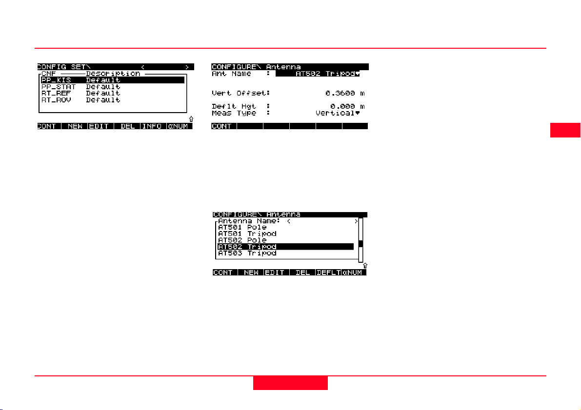
match what you type will be automatically highlighted. This is case sensitive.
Alternatively you can move down the
list item by item using the cursor
keys.
Alternatively you can move down the
list item by item using the cursor
keys.
Pressing Shift will reveal HOME (F2),
END (F3), PG UP (F4) (Page Up) and
PG DN (F5) (Page Down) keys. You
may also use these keys to scroll up
and down the list.
When a drop down list box is available, a small arrow appears next to
the selected item, as with Ant Name
shown below.
Technical Reference Manual-4.0.0en
Press the right or left cursor key to
cycle through the choices or press
ENTER to make the drop down box
appear.
A search field will appear at the top of
the list box with a blinking cursor. If
you know the name of the item you
are search for you may type in the
first few letters. The item(s) that
85
Pressing SHIFT will reveal HOME
(F2), END (F3), PG UP (F4) (Page
Up) and PG DN (F5) (Page Down)
keys. You may also use these keys to
scroll up and down the list.
4. TR500 Terminal Overview

5. Configuring the Receiver
The receiver has numerous
parameters and functions which can
be configured by the user.
Different Configuration Sets are used
for different measuring techniques.
Several default Configuration Sets
are programmed into the receiver
before delivery. These default files
should cover the majority of
applications.
However, you also have the
opportunity to define your own
Configuration Sets. You may define
several Configuration Sets to cover
every type of operation that you are
likely to carry out. This can be done
using the TR500 Terminal.
There are two methods for defining
the Configuration. You can select
Configure from the Main Menu or
press the CONFIG key.
Selecting Configure from the Main
Menu enables a sequential
configuration. Parameters can either
be defined one after each other or
explicitly selected from a list. These
parameters are saved permanently in
the Configuration Set and will be used
as defaults each time the
Configuration Set is used.
Pressing the CONFIG key enters a
menu from which you can choose the
parameter you wish to define. Certain
infrequently used parameters are only
available through the CONFIG key
and are not contained in the
sequential configuration.
It is recommended that the CONFIG
key is only used when you are already
measuring and realize that you need
to change a parameter temporarily
(for the duration of the current
survey), or need to configure a
parameter not contained in the
sequential configuration.
When Configure is selected from the
Main Menu there are two
configuration levels available,
Standard and Advanced. Standard
is recommended for most users.
Advanced enables definition of
parameters required for specialized
applications.
To start defining a Configuration Set,
attach the Terminal to the Receiver
directly or connect it using a Lemo
cable.
Switch on the Receiver and Terminal
by pressing the ON/OFF key.
5. Configuring the Receiver
86
Technical Reference Manual-4.0.0en

The following screen will appear the
first time you switch on.
The following screen will appear:
Pressing INFO (F5) toggles between
the date of creation, creator and
description of the Configuration Sets.
Entering a new Configuration Set
After NEW (F2) has been selected,
the following screen will appear.
The most frequently used functions
are displayed. Use SHOW/HIDE (F4)
to reveal/hide all of the functions.
This chapter covers configuration
using the sequential configuration
(Configure) from the Main Menu.
Details about configuration using the
CONFIG key can be found in Chapter
9.
Select Configure from the Main
Menu. Press CONT (F1).
Technical Reference Manual-4.0.0en
You can select a Configuration Set by
moving up and down the list and
pressing CONT (F1) or entering the
name of the Configuration Set. Press
EDIT (F3) to edit it. Changes in
default Configuration Sets are only
temporary until the sensor is turned
of. Permanent changes, require the
creation of a new Configuration Set.
To enter a new Configuration Set
press NEW (F2).
To delete a Configuration Set press
DEL (F4). You will be asked for
confirmation before the Configuration
Set is deleted.
87
Enter the Name and, if required a
Description and Creator. Press the
ENTER key after each entry. Press
CONT (F1) when you are finished.
If you create a new Configuration Set
a copy of the highlighted
Configuration Set will be created.
5. Configuring the Receiver

5.1 Configuring the Receiver for Static and Rapid Static Operations
This section covers configuration of
the receiver for post-processed
Static, Rapid Static or Kinematic
Reference operations.
Highlight the Configuration Set you
wish to edit and press EDIT (F3).
Note that you cannot edit default
Configuration Sets. You have to
create a new Set and then edit it.
Operation Mode
Select the Operation Mode that you
require. The Operation Mode defines
which Configuration screens will be
available to you.
You may choose between Standard
and Advanced. Standard is
recommended for most users.
Advanced enables definition of
parameters required for specialized
applications.
When you have made your selection
press CONT (F1) to go through the
fixed order of parameter panels.
Or press LIST (F6) to get a listing of
the available parameter panels which
can then be accessed individually
with CONT (F1). Changes are
automatically stored at the end of the
list. Changes in individual parameter
panels can be stored with STORE
(F3) without the need to go to the end
of the list.
The Standard Operation Mode is
described from here on. The extra
configurable features available when
Advanced is selected are described in
section 5.1.1.
5. Configuring the Receiver
88
Technical Reference Manual-4.0.0en

Antenna
Select the Antenna configuration that
you are using.
Ant. Name - Displays and selects the
currently selected antenna setup.
Meas Type - Also, enter the means
by which the Antenna height was
measured. For the majority of GPS
Antennas (including all Leica antennas), this will be Vertical. The height
of some non-Leica GPS antennas
can only be measured by taking the
slope distance to the outer edge of
the Antenna. If this is the case, select
Slope and enter the averaged value.
You will then be required to enter a
Horizontal Offset also. See Section
2.15.3 for more details on measuring
slope height.
You may select from this list or enter
your own Antenna configuration by
pressing the NEW (F2) key. Note that
the settings from the currently highlighted antenna setup are taken over
as suggested default values.
Vert Offset - Displays the vertical
offset defined in the Antenna setup
(Ant Name).
Deflt Hgt - Displays a default height
for the Antenna setup. This is of little
use for Static or Rapid Static applications where the Antenna height differs
with each setup.
Technical Reference Manual-4.0.0en
To select an antenna setup, highlight
Ant. Name and press ENTER to
open the drop down box. All of the
existing antenna setups are listed.
89
Most Static and Rapid Static Surveys
or Reference Stations are carried out
using a tripod or pillar setup.
When a factory default tripod setup is
chosen, the Vertical Offset is automatically set at 0.36m. You will only
need to measure the height with the
height hook when setting up over a
point.
5. Configuring the Receiver

Note that factory default antenna
setups contain an elevation dependent correction model. This is not
seen by the user. When setting up
your own configuration with the
Receiver, this model is not taken over.
This model is required for real-time
rover operations. If you need to input
your own antenna setup and it requires an antenna correction model,
use SKI Pro to configure the antenna
setup and transfer it to the Receiver.
Use the DEFLT (F5) key to reveal
factory default Antenna configurations
with current System 500 GPS Antennas. This will then change to ALL.
Use ALL (F5) to reveal System 300
Antenna configurations also. You can
pick out the Antenna configurations
that you will use the most and delete
the rest. All possible factory default
Antenna configurations may still be
accessed in the future by using the
DEFLT and ALL keys.
Position
This screen defines the way in which
position is displayed. These settings
are mostly used for Real-Time Rover
setups.
Advice on calculating Antenna
heights and offsets for Leica and nonLeica Antennas is given in Chapter
2.15.
Use the EDIT (F3) key to edit the
highlighted Antenna configuration.
Note that factory default Antenna
configurations can only be viewed
and not edited.
Use the DEL (F4) key to delete an
Antenna configuration.
5. Configuring the Receiver
90
Update Rate - Defines the rate at
which the position will be updated on
the display.
Coord Sys - You may select a
coordinate system which will be used
to display the positions. The WGS84
coordinate system will always be
available and should be sufficient for
Static/Rapid Static work. You may
determine other coordinate systems
in SKI Pro and upload them or you
may determine other coordinate
Technical Reference Manual-4.0.0en

systems in the field using
Applications\Determine Coord
System (see section 11.1).
Further options are available on this
screen in Advanced mode. See
section 5.1.1 for details.
Highlight Coord Sys and press
ENTER to reveal the list of coordinate
systems currently available.
(F4) to delete the selected coordinate
system and INFO (F5) to reveal the
type of transformation used.
When NEW (F2) is pressed, the
following screen appears.
Coord Sys - Defines the name of the
new coordinate system.
Further advice on Coordinate Systems is given in Section 11.
When using EDIT (F3) the same
descriptions apply.
Press CONT (F1) to return to the
CONFIGURE\Position screen.
Select the coordinate system that you
wish to use.
Use NEW (F2) to define a new
coordinate system. Use EDIT (F3) to
edit a coordinate system. Use DEL
Technical Reference Manual-4.0.0en
When you have set the parameters
press CONT (F1) to return to the
CONFIGURE\Position screen.
91
5. Configuring the Receiver

Formats
You can configure the way in which
information is presented when
surveying.
Format Grid - The format of grid
coordinates if they are being used.
Format Geodetic - The format of
geodetic coordinates if they are being
used.
Quality Type - The way in which the
quality of a position is displayed in the
Main Survey screen. This is Hardwired to DOP for Static/Rapid Static
Configurations. It will display a
Dilution of Precision according to the
components defined.
Defined by - Defines the components
used to calculate the DOP. The
definitions of the DOP are as follows:
Height - VDOP
Pos - HDOP
Pos + Hgt - PDOP
Pos + Hgt + Time - GDOP
OCUPY Counter - Defines how the
length of time spent occupying a point
is displayed. Select from Time -
normal time or Observations - the
number of observations recorded.
Coding
If you wish to select a coding system
press ENTER and choose from
Thematical or Free coding. Complete
descriptions of the coding systems
used by System 500 are given in
Chapter 8.
Press CODES (F3) to review the
codes in the chosen codelist. You
may also edit the codelist here.
5. Configuring the Receiver
92
Technical Reference Manual-4.0.0en

Real-Time
For Static or Rapid Static postprocessing operations select None
and press CONT (F1).
Logging
Log Static Obs - Switches logging on
or off when the Receiver is in Static
mode. The receiver has to be
stationary.
Obs Rate - The rate at which
observations will be logged. For Static
observations over long baselines and
long periods of time 15-30 seconds is
a reasonable rate. For Rapid Static
applications, 10-15 seconds is
normally used. For Reference
stations for post-processed and realtime kinematic rovers, the rate should
be set the same as at the Rover.
Log Moving Obs - Only available
when Log Static Obs = YES. Sets
the observation rate when the
receiver is in Moving mode. This is
only used in Real-Time kinematic and
Post-Processed kinematic operations.
Log Auto Positions - Will
automatically log positions at a
specified rate. This is mostly used for
real-time rover operations. See
section 5.4 for details.
Press CONT (F1) to continue to the
next screen.
Further options are available on this
screen in Advanced mode. See
section 5.1.1 for details.
Technical Reference Manual-4.0.0en
93
5. Configuring the Receiver

Occupation Settings
These settings control the way in
which points are occupied and
recorded.
OCUPY Mode - Sets the way in
which coordinates will be recorded for
a point. For Static, Rapid Static and
Post-processed Reference Station
applications Normal only will be
available.
This means that observations will be
recorded until the STOP key is
pressed. The last observation that is
recorded is the one that expired
directly before STOP was pressed.
Auto Store - Allows you to
automatically store a point after the
STOP key has been pressed.
Further options are available on this
screen in Advanced mode. See
section 5.1.1 for details.
Id Templates
An Id template is used to pre-define a
Point Id. This feature is mainly used
in post-processed and real-time
kinematic operations where many
points are collected quickly. For
Static, Rapid Static and Real-Time
Reference operations, set all fields to
No template used.
Further options are available on this
screen in Advanced mode. See
section 5.1.1 for details.
Press CONT (F1) to complete the
configuration. You will return to the
Main Menu.
5. Configuring the Receiver
94
Technical Reference Manual-4.0.0en

5.1.1 Advanced Operation Mode for Static and Rapid Static
The Advanced Mode contains extra
configurable parameters that may be
required for certain specialized
applications.
Select Advanced in
CONFIGURE\Operation Mode.
Only the screens that differ from
those seen in Standard Mode are
described here.
Position
In addition to the functionality given in
Standard mode, details about the
chosen coordinate system are given.
Residuals - Available when editing a
coordinate system. The method by
which residuals will be distributed
throughout the transformation area is
displayed.
This may help the transformation
result be more realistic and help
disperse any strains in the
transformation. 1/Dist, 1/Dist2 and 1/
3/2
Dist
distributes the residuals of the
control points according to the
distance between each control point
and the newly transformed point.
Multiquadratic distributes the
residuals using a multiquadratic
interpolation approach.
Transform - The name of the
transformation set used is displayed.
Ellipsoid - The name of the local
ellipsoid is displayed.
Projection -The name of the
projection used is displayed.
Geoid Model - The name of the
geoid model used is displayed.
CSCS Model - The name of the
CSCS model used is displayed.
Note that the details that are
displayed depend upon the type of
transformation used. Certain types of
transformation do not use all of the
described parameters to calculate
local coordinates.
Technical Reference Manual-4.0.0en
95
5. Configuring the Receiver

Logging
In addition to the functionality given in
Standard mode, you can also specify
the observables to be recorded and
access further functionality via the
FILES (F6) key.
Observables - Defines what is
recorded in the raw GPS data.
Extended records extra observables
including the Doppler observable.
Pressing the FILES (F6) key enables
you to configure further options.
Log File Segments - Will split up
the recorded data into files of a
specific time-based length unless 1
File is selected. If a time is selected
the option Split Tracks will become
available. Select No will only record
data into a new file if the time is
reached and a new track is observed.
Auto Del Log Files - Will delete the
recorded data after the specified
length of time unless Never is selected.
Press CONT (F1) to return to
CONFIGURE\Logging.
Occupation Settings
Additional functionality available in
this panel over Standard mode is
Auto OCUPY, Auto Stop, STOP PPRC and END Survey.
Auto OCUPY - will automatically
occupy the point as soon as the
survey is started. Timed is chosen for
automatic point occupations at a
certain time. The time is specified in
the SURVEY panel.
Auto Stop - will automatically stop
the measurements according to the
setting in the STOP P-PRC function.
The measurements stop when the
criteria for the setting reach 100%.
5. Configuring the Receiver
96
Technical Reference Manual-4.0.0en

STOP P-PRC - Defines the method
used for Auto Stop when Auto Stop is
set to YES.
When Auto Stop is set to NO a
percentage value will be displayed
next to the Time or Epochs in the
Main Survey screen. This indicates
how much of the Auto Stop criteria
has elapsed. The Auto Stop criteria is
defined using the P-PRC (F5) key
(see below).
END Survey - Defines how the
survey will be ended. Manual lets you
exit the survey yourself. Automatic
will exit the survey automatically.
Auto & Shut-down will exit the
survey and turn the sensor off.
When one of the STOP P-PRC
options is selected the P-PRC (F5)
key will become available. Pressing
this key will enable you to configure
the option you have selected.
When:
Time is selected, set the required
observation time for each point. The
time starts counting when OCUPY is
pressed. The Receiver stops recording when the set length of time is
reached.
STOP&GO Indicator is selected, set
the baseline range. When measuring,
an observation time will be calculated
based on the selected baseline
range, the number of available
satellites and the GDOP. This is
displayed as a percentage value.
Observations is selected, set the
number of epochs that should be
recorded at each point.
# of Sats is selected, set the length of
time to observe depending on the
number of satellites available. You
may edit the value for each number of
satellites. Should the number of
available satellites change during
observations, the observations
already recorded will be taken into
account. Should the number of
satellites decrease, more time will be
added. Should the number of satellites increase, time will be subtracted.
The Receiver stops recording when
the time limit is reached.
Press CONT (F1) to return to
CONFIGURE\Occupation Settings.
Technical Reference Manual-4.0.0en
97
5. Configuring the Receiver

Working Example
Application - Post Processed Rapid Static Observation Recording
Technique - Rapid Static
Id Templates
Id Templates are not normally of use
for Static, Rapid Static or Kinematic
Reference Stations and should be set
to No Template Used.
Requirement - You wish to view the Stop and Go Indicator on the Main
Survey screen but do not want to automatically stop the survey.
Settings -
Other Settings - Use P-PRC (F5) to set the Baseline Length.
Field Procedure - After pressing OCUPY the time or epoch counter will
start. The Stop and Go Indicator percentage value will be shown in brackets
next to this. It will run until STOP is pressed. The observations will not stop
being recorded at 100% automatically. Further information regarding the
STOP & GO indicator is available in STATUS\SURVEY\STOP&GO
Indicator.
5. Configuring the Receiver
98
However, should you wish to use
them, you will find you may also
configure Id Templates for Auxiliary
Points in exactly the same way as for
normal points.
Technical Reference Manual-4.0.0en

5.2 Configuring the Receiver for Post-Processed Kinematic Operations
This section covers configuration of
the receiver for Post-Processed
Kinematic operations.
Operation Mode
Select the Operation Mode that you
require. The Operation Mode defines
which Configuration screens will be
available to you.
You may choose between Standard
and Advanced. Standard is
recommended for most users.
Advanced enables definition of
parameters required for specialized
applications.
When you have made your selection
press CONT (F1) to go through the
fixed order of parameter panels.
can then be accessed individually
with CONT (F1). Changes are
automatically stored at the end of the
list. Changes in individual parameter
panels can be stored with STORE
(F3) without the need to go to the end
of the list.
The Standard operation mode is
described from here on. The extra
configurable features available when
Advanced is selected are described in
Section 5.2.1.
Technical Reference Manual-4.0.0en
Or press LIST (F6) to get a listing of
the available parameter panels which
99
5. Configuring the Receiver

Antenna
Select the Antenna configuration that
you are using.
Ant. Name - Displays and selects the
currently selected antenna setup.
Vert Offset - Displays the vertical
offset defined in the Antenna setup
(Ant Name).
Deflt Hgt - Displays a default height
for the Antenna setup. If the antenna
will always be mounted at a fixed
height (E.g. on a pole or always at the
same fixed location), enter the value.
You will also get a chance to enter the
height for each set up during survey
operations.
Meas Type - Also, enter the means
by which the Antenna height was
measured. For kinematic measurements using a pole, this will be
Vertical.
To select an antenna setup, highlight
Ant. Name and press ENTER to
open the drop down box. All of the
existing antenna configurations are
listed.
You may select from this list or enter
your own antenna configuration by
pressing the New (F2) key and
entering the required information.
Most Post-Processed Kinematic
Surveys are carried out using the
System 500 pole. When a factory
default pole setup is selected, (AT501
Pole/AT502 Pole) the Vertical Offset
is set automatically at zero and the
Deflt Hgt at 2.00m. Note that the
settings from the currently highlighted
antenna setup are taken over as
suggested default values.
Advice on calculating Antenna
Heights and offsets for Leica and
non-Leica Antennas is given in
Chapter 2.15.
Use the Edit (F3) key to edit the
highlighted Antenna configuration.
Use the DEL (F4) key to delete an
Antenna configuration.
Use the DEFLT (F5) key to reveal
default antenna configurations with
current System 500 GPS antennas.
This will then change to ALL.
5. Configuring the Receiver
100
Technical Reference Manual-4.0.0en
 Loading...