


Leica RTC360
User Manual
V
ersion 1.0
English

Introduction
Congratulations on the purchase of a Leica RTC360 series instrument.
This manual contains important safety directions as well as instructions for setting up the p
roduct and operating it. Refer to "1 Safety Directions" for further
information.
Read carefully through the User Manual before you switch on the product.
To ensure safety when using accompanying battery charger, also observe the
dir
ections and instructions contained in the User Manual of the battery charger.
The model and serial number of your product are indicated on the type plate.
A
lways refer to this information when you need to contact your agency or
Leica Geosystems authorised service centre.
•
Windows is a r
egistered trademark of Microsoft Corporation in the United
States and other countries
All other trademarks are the property of their respective owners.
On the last page of this manual, you can find the address of Leica Geosystems
he
adquarters. For a list of regional contacts, please visit
http://leica-geosystems.com/contact-us/sales_support.
Name Description/Format
Leica RTC360
Quick Guide
Provides an overview of the product together with
t
echnical data and safety directions. Intended as a
quick reference guide.
ü ü
Leica RTC360
User Manual
All instructions required in order to operate the
product to a basic level are contained in the User
Manual. Provides an overview of the product
together with technical data and safety directions.
-
ü
Leica RTC360
tutorial videos
How-to videos explaining the basic workflow.
https://www.youtube.com/playlist?
list=PL0td7rOVk_IWwYh5GDTKjP--nTu3n0WzK
- -
Refer to the following resources for all RTC360 documentation/softw
are:
•
the sup
plied USB documentation card
•
https://myworld.leica-geosystems.com
Purchase
Product identification
Trademarks
Leica Geosystems
a
ddress book
Available documentat
ion
2

Table of Contents
1 Safety Directions 5
1.1 General Introduction 5
1.2 Definition of Use 5
1.3 Limits of Use 6
1.4 Responsibilities 6
1.5 Hazards of Use 7
1.6 Laser Classification 10
1.6.1 General 10
1.6.2 Scanning Laser 11
1.7 Electromagnetic Compatibility EMC 11
1.8 FCC Statement, Applicable in U.S. 13
1.9 ICES-003 Statement, Applicable in Canada 15
2 Description of the System 16
2.1 Packing / Unpacking the Instrument 16
2.2 Container Contents 16
2.3 Backpack Contents 17
2.4 Instrument Components 17
2.5 System Components 18
2.6 System Concept 18
2.6.1 Power Concept 18
2.6.2 Data Storage Concept 18
3 User Interface 20
3.1 Power Button 20
3.2 Device Status 20
3.3 Screen 22
4 Operation 23
4.1 Instrument Setup 23
4.1.1 General Information 23
4.1.2 Lightweight Tripod Setup 23
4.1.3 Heavy Duty Tripod Setup 24
4.2 Power Supply 24
4.2.1 Batteries 24
4.2.2 Exchanging the Batteries 25
4.3 Operation - Getting Started 26
4.4 Imaging 27
4.5 Scanning 27
4.5.1 Ambient Conditions 27
4.5.2 Onboard Controls 28
4.5.3 Troubleshooting 30
4.5.4 Field of View (FoV) 31
4.6 Data Transfer 31
4.7 Working with the USB Data Storage Device 31
5 Care and Transport 33
5.1 Transport 33
5.2 Field Check 33
5.3 Storage 33
5.4 Cleaning and Drying 34
5.5 Glass Cleaning Procedure 34
6 Technical Data 36
6.1 General Technical Data of the Product 36
6.2 System Performance 36
Table of Contents 3

6.3 Laser System Performance 37
6.4 Electrical Data 38
6.4.1 Pin Assignment of Lemo Ports 39
6.5 Environmental Specifications 40
6.5.1 RTC360 40
6.5.2 GEB361 Battery and GEV282 AC/DC Power Supply 40
6.6 Dimensions 41
6.7 Weight 43
6.8 Accessories 43
6.9 Conformity to National Regulations 44
6.9.1 RTC360 44
6.9.2 Dangerous Goods Regulations 44
7 Software Licence Agreement 46
4 Table of Contents

1 Safety Directions
1.1 General Introduction
The following directions enable the person responsible for the product, and the
p
erson who actually uses the equipment, to anticipate and avoid operational
hazards.
The person responsible for the product must ensure that all users understand
these directions and adhere to them.
Warning messages are an essential part of the safety concept of the instrumen
t. They appear wherever hazards or hazardous situations can occur.
Warning messages...
•
mak
e the user alert about direct and indirect hazards concerning the use
of the product.
•
contain general rules of behaviour.
For the users‘ safety, all safety instructions and safety messages shall be
s
trictly observed and followed! Therefore, the manual must always be available
to all persons performing any tasks described here.
DANGER, WARNING, CAUTION and NOTICE are standardised signal words for
identifying levels of hazards and risks related to personal injury and property
damage. For your safety, it is important to read and fully understand the following table with the different signal words and their definitions! Supplementary safety information symbols may be placed within a warning message as
well as supplementary text.
Type Description
DANGER
Indicates an imminently hazardous situation
which, if no
t avoided, will result in death or
serious injury.
WARNING
Indicates a potentially hazardous situation or
an unin
tended use which, if not avoided,
could result in death or serious injury.
CAUTION
Indicates a potentially hazardous situation or
an unin
tended use which, if not avoided,
may result in minor or moderate injury.
NOTICE
Indicates a potentially hazardous situation or
an unintended use which, if not avoided,
may result in appreciable material, financial
and environmental damage.
☞
Important paragraphs which must be adhered
to in practice as they enable the product to
be used in a technically correct and efficient
manner.
1.2 Definition of Use
•
Me
asuring horizontal and vertical angles.
•
Measuring distances.
•
Scanning objects.
•
Capturing and recording images.
•
Recording measurements.
Description
About warning
m
essages
Intended use
Safety Directions 5

•
Co
mputing with software.
•
Remote control of product.
•
Data communication with external appliances.
•
Us
e of the product without instruction.
•
Use outside of the intended use and limits.
•
Disabling safety systems.
•
Removal of hazard notices.
•
Opening the product using tools, for example screwdriver, unless this is
permitted for certain functions.
•
Modification or conversion of the product.
•
Use after misappropriation.
•
Use of products with recognisable damages or defects.
•
Use with accessories from other manufacturers without the prior explicit
approval of Leica Geosystems.
•
Inadequate safeguards at the working site.
•
Deliberate dazzling of third parties.
1.3 Limits of Use
Suitable for use in an atmosphere appropriate for permanent human habitatio
n: not suitable for use in aggressive or explosive environments.
WARNING
Working in hazardous areas, or close to electrical installations or similar sit
uations.
Life Risk.
Precautions:
▶
Local safety authorities and safety experts must be contacted by the person responsible for the product before working in such conditions.
The following advice is only valid for AC adapters and chargers.
Suitable for use in dry environments only and not under adverse conditions.
1.4 Responsibilities
Leica Geosystems AG, CH-9435 Heerbrugg, hereinafter referred to as
Leica G
eosystems, is responsible for supplying the product, including the User
Manual and original accessories, in a safe condition.
Reasonably foreseeable misuse
Environment
☞
Environment
Manufacturer of the
pr
oduct
6 Safety Directions

The person responsible for the product has the following duties:
•
T
o understand the safety instructions on the product and the instructions
in the User Manual.
•
To ensure that it is used in accordance with the instructions.
•
To be familiar with local regulations relating to safety and accident prevention.
•
To inform Leica Geosystems immediately if the product and the application
becomes unsafe.
•
To ensure that the national laws, regulations and conditions for the operation of the product are respected.
1.5 Hazards of Use
WARNING
Distraction or loss of attention
Dur
ing dynamic applications there is a danger of accidents occurring if the user
does not pay attention to the environmental conditions around, for example
obstacles, excavations or traffic.
Precautions:
▶
The person responsible for the product must make all users fully aware of
the existing dangers.
WARNING
Inadequate securing of the working site.
T
his can lead to dangerous situations, for example in traffic, on building sites
and at industrial installations.
Precautions:
▶
Always ensure that the working site is adequately secured.
▶
Adhere to the regulations governing safety, accident prevention and road
traffic.
NOTICE
Dropping, misusing, modifying, storing the product for long periods or
transporting the product
Watch out for erroneous measurement results.
Precautions:
▶
Periodically carry out test measurements, particularly after the product has
been subjected to abnormal use and before and after important measurements.
CAUTION
Moving parts at the product during operation
Risk o
f squeezing extremities or entanglement of hair and/or clothes.
Precautions:
▶
Keep a safe distance to the moving parts.
Person responsible
f
or the product
Safety Directions 7

If the instrument moves unexpectedly during operation, stop the instrument via
us
er interface (display, key) or alternatively remove the battery or main power
source to prevent further movements.
CAUTION
Not properly secured accessories.
If the ac
cessories used with the product are not properly secured and the
product is subjected to mechanical shock, for example blows or falling, the
product may be damaged or people can sustain injury.
Precautions:
▶
When setting up the product, make sure that the accessories are correctly
adapted, fitted, secured, and locked in position.
▶
Avoid subjecting the product to mechanical stress.
WARNING
Exposure of batteries to high mechanical stress, high ambient temperat
ures or immersion into fluids
This can cause leakage, fire or explosion of the batteries.
Precautions:
▶
Protect the batteries from mechanical influences and high ambient temperatures. Do not drop or immerse batteries into fluids.
WARNING
Short circuit of battery terminals
If ba
ttery terminals are short circuited e.g. by coming in contact with jewellery,
keys, metallised paper or other metals, the battery can overheat and cause
injury or fire, for example by storing or transporting in pockets.
Precautions:
▶
Make sure that the battery terminals do not come into contact with metallic objects.
WARNING
Inappropriate mechanical influences to batteries
Dur
ing the transport, shipping or disposal of batteries it is possible for inappro-
priate mechanical influences to constitute a fire hazard.
Precautions:
▶
Before shipping the product or disposing it, discharge the batteries by the
product until they are flat.
▶
When transporting or shipping batteries, the person in charge of the product must ensure that the applicable national and international rules and
regulations are observed.
▶
Before transportation or shipping, contact your local passenger or freight
transport company.
☞
8 Safety Directions

WARNING
If the product is improperly disposed of, the following can happen:
•
If p
olymer parts are burnt, poisonous gases are produced which may
impair health.
•
If batteries are damaged or are heated strongly, they can explode and
cause poisoning, burning, corrosion or environmental contamination.
•
By disposing of the product irresponsibly you may enable unauthorised
persons to use it in contravention of the regulations, exposing themselves
and third parties to the risk of severe injury and rendering the environment
liable to contamination.
•
The product includes parts of Beryllium inside. Any modification of some
internal parts can release dust or fragments, creating health hazard.
Precautions:
▶
The product must not be disposed with household waste.
Disp
ose of the product appropriately in accordance with
the national regulations in force in your country.
Always prevent access to the product by unauthorised
personnel.
Product-specific treatment and waste management information can be
received from your Leica Geosystems distributor.
☞
Applies only for California. The product contains CR Lithium Cell(s)
with p
erchlorate material inside – special handling may apply.
See http://www.dtsc.ca.gov/hazardouswaste/perchlorate/
WARNING
Lightning strike
If the p
roduct is used with accessories, for example masts, staffs, poles, you
may increase the risk of being struck by lightning.
Precautions:
▶
Do not use the product in a thunderstorm.
WARNING
Improperly repaired equipment
Risk o
f injuries to users and equipment destruction due to lack of repair knowl-
edge.
Precautions:
▶
Only Leica Geosystems authorised service centres are entitled to repair
these products.
Safety Directions 9

For the AC/DC power supply and the battery charger:
WARNING
Unauthorised opening of the product
Either o
f the following actions may cause you to receive an electric shock:
•
Touching live components
•
Using the product after incorrect attempts were made to carry out repairs.
Precautions:
▶
Do not open the product!
▶
Only Leica Geosystems authorised service centres are entitled to repair
these products.
For the AC/DC power supply and the battery charger:
WARNING
Electric shock due to use under wet and severe conditions
If unit b
ecomes wet it may cause you to receive an electric shock.
Precautions:
▶
If the product becomes humid, it must not be used!
▶
Use the product only in dry environments, for example in buildings or vehicles.
▶
Protect the product against humidity.
WARNING
Electric shock due to missing ground connection
If unit is no
t connected to ground, death or serious injury can occur.
Precautions:
▶
The power cable and power outlet must be grounded!
1.6 Laser Classification
1.6.1 General
The following chapters provide instructions and training information about laser
sa
fety according to international standard IEC 60825-1 (2014-05) and technical
report IEC TR 60825-14 (2004-02). The information enables the person
responsible for the product and the person who actually uses the equipment,
to anticipate and avoid operational hazards.
☞
According to IEC TR 60825-14 (2004-02), products classified as laser
class 1, class 2 and class 3R do no
t require:
•
laser safety officer involvement,
•
protective clothes and eyewear,
•
special warning signs in the laser working area
if used and operated as defined in this User Manual due to the low
eye hazard level.
General
10 Safety Directions

☞
National laws and local regulations could impose more stringent
ins
tructions for the safe use of lasers than IEC 60825-1 (2014-05)
and IEC TR 60825-14 (2004-02).
1.6.2 Scanning Laser
The laser incorporated in the product produces an invisible beam, which
emer
ges from the rotating mirror.
The laser product described in this section is classified as laser class 1 in
ac
cordance with:
•
IE
C 60825-1 (2014-05): “Safety of laser products”
These products are safe under reasonably foreseeable conditions of operation
and ar
e not harmful to the eyes provided that the products are used and main-
tained in accordance with this User Manual.
Description Value
Wavelength 1550 nm
Maximum pulse energy 1.6 µJ
Pulse duration 0.5 ns
Maximum pulse repetition frequency
(PRF)
2 MHz
Beam divergence (1/e2, full angle) 0.5 mrad
Mirror rotation 100 Hz
Base rotation 10 mHz
60°
60°
0°
0°
360°
360°
90°
b
a
c
0016139_001
Model: RTC360
Equip. No.: 1234567
Power : 24V 75W max.
Leica Geosystems AG
CH-9435 Heerbrugg
Manufactured: 01.2018
Made in Switzerland
Art. No.: 838300
S.No.: 2980001
WLAN PW: 12345678
KCC - CRM - ABC XXXXXXXXXXXXXX
R 007 - AC0271
Complies with FDA performance standards for laser
products exept for deviations pursuant to Laser Notice No.
50, dated June 24, 2007
This device complies with Part 15 of the FCC Rules.
Operation is subject to the following two conditions: (1)
this device may not cause harmful interference, and (2) this
device must accept any interference received, including
interference that may cause undesired operation.
IP54
This device contains:
FCC ID: N6C-SXPCEAN2
IC: 4608A-SPCEAN2
IEC 60825-1: 2014
a Laser beam
b
Vertical laser scanning area
c Horizontal laser scanning area
Class 1 Laser
Pr
oduct
according to IEC
60825-1
(2014-05)
1.7 Electromagnetic Compatibility EMC
The term Electromagnetic Compatibility is taken to mean the capability of the
p
roduct to function smoothly in an environment where electromagnetic radiation and electrostatic discharges are present, and without causing electromagnetic disturbances to other equipment.
General
Labelling
Description
Safety Directions 11

WARNING
Electromagnetic radiation
Elec
tromagnetic radiation can cause disturbances in other equipment.
Precautions:
▶
Although the product meets the strict regulations and standards which are
in force in this respect, Leica Geosystems cannot completely exclude the
possibility that other equipment may be disturbed.
CAUTION
Use of the product with accessories from other manufacturers. For
ex
ample field computers, personal computers or other electronic equip-
ment, non-standard cables or external batteries
This may cause disturbances in other equipment.
Precautions:
▶
Use only the equipment and accessories recommended by Leica Geosys-
tems.
▶
When combined with the product, they meet the strict requirements stipu-
lated by the guidelines and standards.
▶
When using computers, two-way radios or other electronic equipment, pay
attention to the information about electromagnetic compatibility provided
by the manufacturer.
CAUTION
Intense electromagnetic radiation. For example, near radio transmitters, transp
onders, two-way radios or diesel generators
Although the product meets the strict regulations and standards which are in
force in this respect, Leica Geosystems cannot completely exclude the possibility that function of the product may be disturbed in such an electromagnetic
environment.
Precautions:
▶
Check the plausibility of results obtained under these conditions.
CAUTION
Electromagnetic radiation due to improper connection of cables
If the p
roduct is operated with connecting cables attached at only one of their
two ends, for example external supply cables, interface cables, the permitted
level of electromagnetic radiation may be exceeded and the correct functioning
of other products may be impaired.
Precautions:
▶
While the product is in use, connecting cables, for example product to
external battery, product to computer, must be connected at both ends.
12 Safety Directions

WARNING
Use of product with radio or digital cellular phone devices
Elec
tromagnetic fields can cause disturbances in other equipment, in installations, in medical devices, for example pacemakers or hearing aids and in aircraft. It can also affect humans and animals.
Precautions:
▶
Although the product meets the strict regulations and standards which are
in force in this respect, Leica Geosystems cannot completely exclude the
possibility that other equipment can be disturbed or that humans or animals can be affected.
▶
Do not operate the product with radio or digital cellular phone devices in
the vicinity of filling stations or chemical installations, or in other areas
where an explosion hazard exists.
▶
Do not operate the product with radio or digital cellular phone devices
near to medical equipment.
▶
Do not operate the product with radio or digital cellular phone devices in
aircraft.
1.8 FCC Statement, Applicable in U.S.
☞
The greyed paragraph below is only applicable for products without
r
adio.
WARNING
This equipment has been tested and found to comply with the limits for a
C
lass B digital device, pursuant to part 15 of the FCC rules.
These limits are designed to provide reasonable protection against harmful
interference in a residential installation.
This equipment generates, uses and can radiate radio frequency energy and,
if not installed and used in accordance with the instructions, may cause
harmful interference to radio communications. However, there is no guarantee that interference will not occur in a particular installation.
If this equipment does cause harmful interference to radio or television
reception, which can be determined by turning the equipment off and on,
the user is encouraged to try to correct the interference by one or more of
the following measures:
•
R
eorient or relocate the receiving antenna.
•
Increase the separation between the equipment and the receiver.
•
Connect the equipment into an outlet on a circuit different from that to
which the receiver is connected.
•
Consult the dealer or an experienced radio/TV technician for help.
CAUTION
Changes or modifications not expressly approved by Leica Geosystems for
c
ompliance could void the user's authority to operate the equipment.
Safety Directions 13

0016140_001
0
016140_001
Model: RTC360
Equip. No.: 1234567
Power : 24V 75W max.
Leica Geosystems AG
CH-9435 Heerbrugg
Manufactured: 01.2018
Made in Switzerland
Art. No.: 838300
S.No.: 2980001
WLAN PW: 12345678
KCC - CRM - ABC XXXXXXXXXXXXXX
R 007 - AC0271
Complies with FDA performance standards for laser
products exept for deviations pursuant to Laser Notice No.
50, dated June 24, 2007
This device complies with Part 15 of the FCC Rules.
Operation is subject to the following two conditions: (1)
this device may not cause harmful interference, and (2) this
device must accept any interference received, including
interference that may cause undesired operation.
IP54
This device contains:
FCC ID: N6C-SXPCEAN2
IC: 4608A-SPCEAN2
IEC 60825-1: 2014
XXXXXXXX-XXXXXX
A/S:+82 31 620 6252
전지
Type : GEB361
Li-Ion Battery
11.1 V / 5.6 Ah
15 A / 62 Wh
Leica Geosystems AG, CH-9435 Heerbrugg
Art.No.: 799191
S.No.: XXXXX
Made in China
This device complies with part 15 of the FCC Rules.
Operation is subject to the following two conditions:
(1) This device may not cause harmful interference, and
(2) this device must accept any interference received,
including interference that may cause undesired operation.
Manufactured by Huizhou Longji Electronics Co., Ltd.
0016141_001
0000001
This device co mplies with par t 15 of the FCC Rules.
Operation is s ubject to the foll owing two condit ions:
(1) This device may not ca use harmful inte rference, and
(2) this device must accept any interference received,
including interference that may cause undesired operation.
HU071647-14001A
MSIP-REM-RRC-GKL341
+82-2-565-4272
I.T.E. Power Supply
E228592
Type : GKL341 Art.No.: 799187
Battery Charger
Input, , , : 100-240 V / 50 -60 Hz / 1.5 A max. / 175 VA
24 V / 2.8 A max.
Output, , , : 16.8 V / 3 A max.
Leica Geos ystems AG
CH-9435 Heerbrugg
Manufacturer, , : RRC power solutions GmbH
, : EMI ASIA LTD
Made in China , ,
0016142_001
16773_001
Labelling RTC360
Labelling GEB361
Labelling GKL341
Labelling GEV282
14 Safety Directions

1.9 ICES-003 Statement, Applicable in Canada
WARNING
This Class (B) digital apparatus complies with Canadian ICES-003.
Ce
t appareil numérique de la classe (B) est conforme à la norme NMB-003
du Canada.
Canada Compliance Statement
T
his device complies with Industry Canada’s license-exempt RSSs. Operation
is subject to the following two conditions:
1. This device may not cause interference; and
2. This device must accept any interference, including interference that
may cause undesired operation of the device.
Canada Déclaration de Conformité
Le présent appareil est conforme aux CNR d’Industrie Canada applicables aux
appareils radio exempts de licence. L’exploitation est autorisée aux deux conditions suivantes:
1. l’appareil ne doit pas produire de brouillage;
2. l’appareil doit accepter tout brouillage radioélectrique subi, même si le
brouillage est susceptible d’en compromettre le fonctionnement.
Safety Directions 15

2 Description of the System
2.1 Packing / Unpacking the Instrument
When in its transport container, the RTC360 can sit in either a face-up or facedown p
osition.
0016201_001
0016
201
001
To take the instrument out of
its c
ontainer, grasp the
instrument at the left and
right side covers, and lift. Use
caution due to the weight of
the instrument (6 kg).
2.2 Container Contents
0016159_002
j
i
h
g
f
e
d
c
b
a
a RTC360 laser scanner
b
GEB361 Lithium-Ion
batteries
c GKL341 Multicharger
Professional 5000
d RTC360 USB flash drive
256 GB
e RTC360 rain cover
f RTC360 Quick Guide
g RTC360 System USB
card
h Tribrach*
i Tribrach adapter*
j RTC360 transport con-
tainer
*optional
Packing and
unpa
cking
Container contents
16 Description of the System

2.3 Backpack Contents
0016153_001
d
c
b
a
a RTC360 laser scanner
b
RTC360 backpack
c GEB361 Lithium-Ion
batteries
d Lightweight tripod
2.4 Instrument Components
0016143_001
a
b
f
e
c
d
d
g
h
n
i
d
j
l
m
k
o
p
k
a Antennas
b
Rotating mirror/laser aperture
c HDR cameras
d Cameras for visual inertial system
e Quick release
f Status LED
g Battery compartment
h Touch screen
i On/Off button
j Fan
k USB slot
l Socket for power supply, 5 pin female
m Ethernet socket, 8 pin female
n Quick release mount
o Fan
p Loudspeaker
Backpack contents
Instrument
comp
onents
Description of the System 17

2.5 System Components
0016158_002
e
d
c
b
a
a RTC360 laser scanner
b
RTC360 USB flash drive
c GEB361 exchangeable batter-
ies
d Lightweight tripod
e Transport container for RTC360
and accessories
2.6 System Concept
2.6.1 Power Concept
Use the batteries, chargers and accessories recommended by Leica Geosystems
t
o ensure the correct operation of the instrument.
Model Power supply
All instrument types Internally by GEB361 battery,
O
R Externally by GEV282 AC power supply
(for indoor use only).
2.6.2 Data Storage Concept
Data is stored on an exchangeable USB data storage device.
The instrument comes with two Leica MS256 USB sticks (exFAT formatted)
which f
it into the USB port of the instrument.
Only use the Leica MS256 USB stick. Other devices are not compatible and may
damage the ins
trument.
Unplugging connecting cables or removing the USB stick during the measuremen
t can cause loss of data. Only remove the USB stick or unplug connecting
cables when the Eject USB stick function has been executed.
The Leica MS256 USB stick is used to transfer data from the instrument to
ex
ternal computers.
System components
General
Power options
Description
Data storage device
☞
☞
Data transfer
18 Description of the System

All data recorded by the instrument and all meta data created by the field app
o
n the remote tablet is stored on the USB stick.
Type Description
Data Scans, images, orientation
Meta data Registration, tags, images
Description of the System 19

3 User Interface
3.1 Power Button
0016145_001
a
a Power button
Power button when the RTC360 is THEN
Press and hold the
bu
tton 1 sec.
off. The RTC360 switches on
and the Power button
starts blinking yellow.
Press and hold the
button 1 sec.
on and ready. The Power button starts
blinking yellow and the
RTC360 switches off.
Press and hold the
button 10 sec.
on. The RTC360 switches off
immediately. Hard shutdown.
3.2 Device Status
The power button and the status LED light up green, yellow or red to show the
o
peration states of the RTC360.
Component Status
Power button lights up continuous.
is blinking.
Status LED
lights up continuous.
is blinking.
Power button
Device status
20 User Interface

Power
button
Status LED Instrument status
The RTC360 is off.
The RTC360 is booting up or
shu
tting down.
The RTC360 is ready.
The RTC360 is recording.
The RTC360 is being moved
and the visual iner
tial system
is recording.
An unrecoverable system
er
ror occurred. Follow the
instructions in the display. If
necessary, shut down the
instrument and reboot again.
If status does not change,
contact the Leica support.
Operation mode
User Interface 21

3.3 Screen
16602_001
f
e
d
c
b
a
a Status field
b
Job field
c Acquisition time
d Start button
e Scan settings
f Setup field
Screen overview
22 User Interface
4 Operation
4.1 Instrument Setup
4.1.1 General Information
The instrument should always be set up on its tripod. Using the tripod specif
ied for the scanning system guarantees maximum stability during scanning
operations.
☞
Always set up the instrument on its tripod. Do not set up the instrumen
t directly on the ground for scanning operations.
☞
It is always recommended to shield the instrument from direct sunlight and avoid uneven temperatures around the instrument.
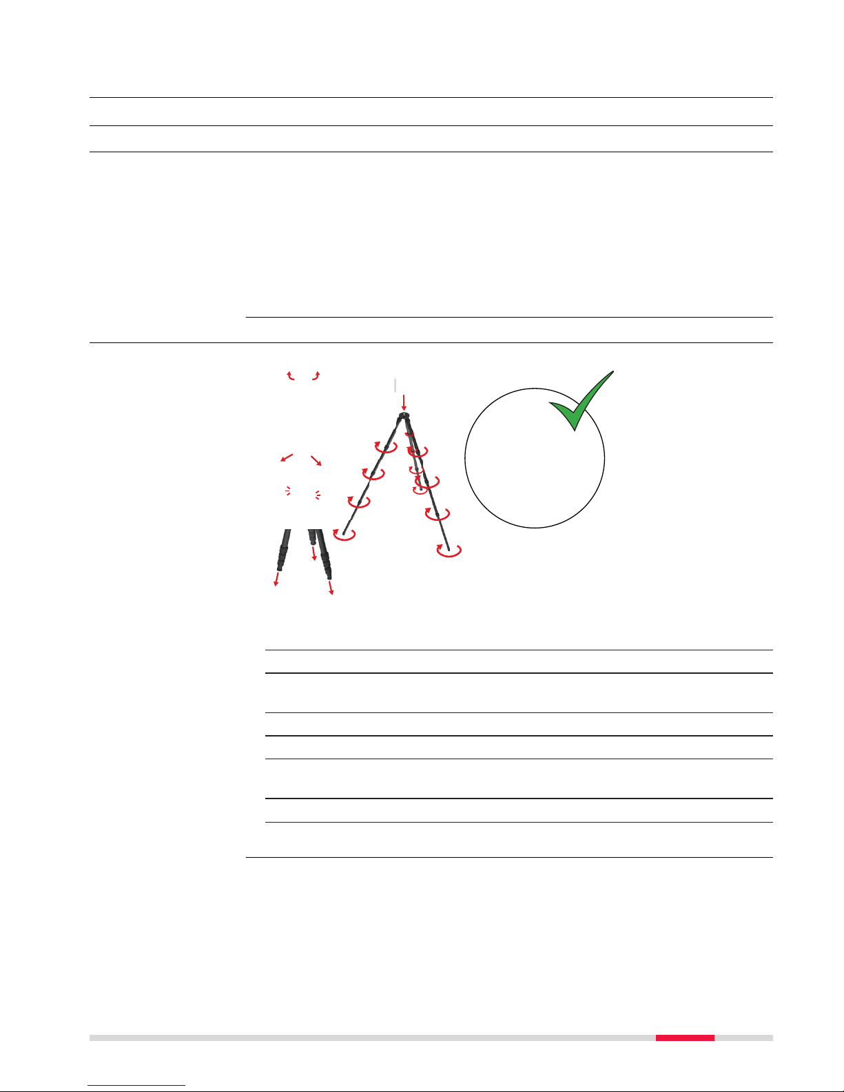
4.1.2 Lightweight Tripod Setup
0016152_001
6
5
4
3
2
1
1. Unlock the locks at the top of the legs.
2. Unfold the legs so that the locks lock in their maximum position.
3. Move the legs back to a fixed position so that the locks click into
plac
e.
4. Extend the tripod legs to allow for a comfortable working posture.
5. Tighten all locking screws at the tripod legs.
☞
Remove the rubber caps at the bottom of the tripod legs to uncover
spikes for usage on a soft ground.
☞
Do not use the spikes on slippery ground.
6. Place the instrument on the quick release mount and secure it.
Use the tripod
Instrument setup
s
tep-by-step
Operation 23
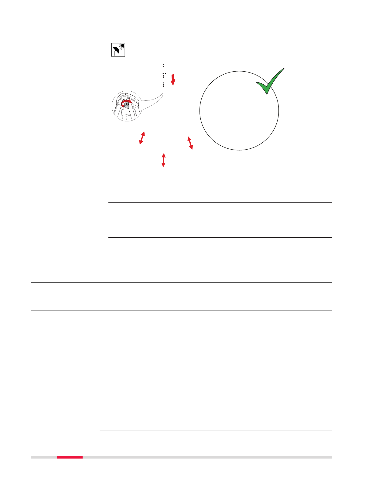
4.1.3 Heavy Duty Tripod Setup
0016155_001
4
3
2
2
1
1
1
☞
Shield the instrument from direct sunlight and avoid uneven tempera
tures around the instrument.
1. Extend the tripod legs to allow for a comfortable working posture.
Ensure that the tripod plate is roughly horizontal.
2. Place the tribrach on the tripod and secure it with the central fixing
screw.
3. Place the tribrach adapter on the tribrach and secure it with the locking knob of the tribrach.
4. Place the instrument on the quick release mount and secure it.
4.2 Power Supply
For details regarding the charging station refer to GKL341 User Manual.
4.2.1 Batteries
•
T
he batteries must be charged before using them for the first time
because they are delivered with an energy content as low as possible.
•
The permissible temperature range for charging is from 0 °C to +40 °C/
+32 °F to +104 °F. For optimal charging, we recommend charging the batteries at a low ambient temperature of +10 °C to +20 °C/+50 °F to +68 °F
if possible.
•
It is normal for the battery to become warm during charging. Using the
chargers recommended by Leica Geosystems, it is not possible to charge
the battery once the temperature is too high.
•
For new batteries or batteries that have been stored for a long time
(> three months), it is effectual to make only one charge/discharge cycle.
•
For Li-Ion batteries, a single discharging and charging cycle is sufficient. We
recommend carrying out the process when the battery capacity indicated
on the charger or on a Leica Geosystems product deviates significantly
from the actual battery capacity available.
Instrument setup
s
tep-by-step
☞
First-time use/
c
harging batteries
24 Operation
•
T
he batteries can be operated from −20 °C to +55 °C/−4 °F to +131 °F.
•
Low operating temperatures reduce the capacity that can be drawn; high
operating temperatures reduce the service life of the battery.
4.2.2 Exchanging the Batteries
NOTICE
The batteries are hot-swappable. Data acquisition requires two batteries inserted into the battery compartment. The instrument does not shut down when
only one battery is inserted.
0016149_001
5
4
321
1 s
1. Open the battery compartment.
2. Remove the left battery from the battery compartment by pushing
the up
per red button to the right.
Remove the right battery from the battery compartment by pushing
the lower red button to the left.
3. Insert the new batteries into the battery compartment.
☞
Ensure that the battery contacts are facing inwards.
4. Close the battery compartment.
5. Turn on the RTC360 to start the boot process.
Operation/
disc
harging
Insert and remove the
ex
changeable batter-
ies
Operation 25

4.3 Operation - Getting Started
1
2
0016235_001
3
1. Press the power button to turn on the RTC360.
2. The RTC360 is starting. The power button and the status LED are
blinking y
ellow.
3. When the user interface is visible, the RTC360 is ready for operation.
The power button and the status LED are now continuously green.
☞
Do not touch or move the RTC360 while the system is recording.
Connect
1 s
0016241_001
6
5
4
32
1
1. Press the power button to turn on the RTC360.
2. The RTC360 is starting. The power button and the status LED are
blinking y
ellow.
3. When the user interface is visible, the RTC360 is ready for operation.
The power button and the status LED are now continuously green.
4. Connect the handheld device with the RTC360.
5. Start the recording and simultaneous data transfer with the handheld device.
Stand-alone operat
ion step-by-step
Operation with handh
eld device connec-
tion step-by-step
26 Operation

6. Start the processing of data on the handheld device.
1. Start the RTC360 and wait until the user interface is visible.
2. On the handheld device select Se
ttings and tap Wi-Fi.
3. Select the network RTC360-298xxxx in the Wi-Fi settings to be con-
nected.
☞
The number xxxx is the serial number of the RTC360.
4. Enter the password.
☞
The instrument specific password is printed on the type
label in the battery compartment, for example "test1111".
Model: RTC360
Equip. No.: 1234567
Power : 24V 75W max.
Leica Geosystems AG
CH-9435 Heerbrugg
Manufactured: 01.2018
Made in Switzerland
Art. No.: 838300
S.No.: 2980001
WLAN PW: 12345678
KCC - CRM - ABC XXXXXXXXXXXXXX
Model:
RTC360
Equip. No.: 1234567
Power
: 24V 75W
Leica Geosystems A
G
C
H-9435 Heerbru
g
g
Manufactured: 01.2
0
Made in Switzerlan
d
16625_001
5. Start the app and connect the instrument.
☞
For further information, refer to the help menu in the app.
4.4 Imaging
The RTC360 has two different types of image sensors:
•
T
hree calibrated cameras for HDR, 360° spherical image acquisition.
•
Five calibrated cameras for the visual inertial system VIS.
0016150_001
a
16151_00216151
002
b
a 3 cameras for HDR imaging b 5 cameras for visual inertial
sys
tem VIS
4.5 Scanning
4.5.1 Ambient Conditions
•
Hig
hly reflective (polished metal, gloss paint)
•
Highly absorbent (black)
•
Translucent (clear glass)
Connecting to a handh
eld device
step-by-step
Description
Imaging
Unfavourable surfaces f
or scanning
Operation 27

☞
Colour, powder or tape these surfaces before scanning if necessary.
•
R
ain, snow or fog may adversely affect measurement quality. Always use
care when scanning in these conditions.
•
Surfaces that are directly illuminated by the sun cause an increased range
noise and therefore a larger measurement uncertainty.
•
If some objects are scanned against the sunlight or a bright spotlight, the
optical receiver of the instrument can be dazzled so heavily that in this
area no measured data is recorded.
If the instrument is brought from a cold environment, for example from storage, in
to a warm and humid environment, the mirror or in extreme cases even
the interior optics can condense. This may cause measurement errors.
☞
Precaution: Avoid rapid temperature changes and give the instrument
time t
o acclimatise.
Dirt on the mirror such as a layer of dust, condensation or fingerprints may
caus
e considerable measuring errors.
4.5.2 Onboard Controls
16630_001
The Start screen is displayed after the system boot
p
rocess. Once it is visible the instrument is ready for
scanning.
Element Description
Status field WiFi enabled.
Internal battery status
USB storage device status
Unfavourable weather
con
ditions for scan-
ning
Temperature changes
during sc
anning
Dirt on the mirror
About the Start
screen
28 Operation

Element Description
Do not remove USB storage device.
Clicking the Se
ttings icon opens the Set-
tings screen.
Job field
Clicking the Job icon opens the list of all
s
tored jobs.
Name of the current scan job.
Time Display of the acquisition time depending on
the s
can settings.
Start
Clicking the S
tart button starts the scan and
image acquisition as defined in the scan settings.
Scan settings
Low scan resolution: 12 mm@10 m, maximum r
ange 130 m
Medium scan resolution: 6 mm@10 m, maximum r
ange 130 m
High scan resolution: 3 mm@10 m, maximum
r
ange 65 m
HDR image acquisition enabled.
HDR image acquisition disabled.
Double Scan enabled.
Double Scan disabled.
Visual inertial system VIS enabled.
Visual inertial system VIS disabled.
Operation 29

Element Description
Setup field Number of setups in current job. Click the
Se
tup field to open the setup list with
thumbnails for each setup.
4.5.3 Troubleshooting
Problem Possible Cause(s) Suggested Remedies
Missing points in
s
can.
Dust, debris or fingerprints on rotating mirror.
Use glass cleaning tissue
to clean the specific
areas.
Problem Possible Cause Suggested Remedies
When switching on
the ins
trument or
starting a scan, the
system switches off
automatically.
Capacity of battery is too
low.
Recharge or change battery.
When switching on
the instrument or
starting a scan, the
system switches off
automatically even
though it was totally
recharged.
Battery charger is defective.
Check the function of the
battery charger. Please
note the charging status
displayed on the battery
charger.
Exchangeable battery is
no longer charging.
At the end of its life time
the exchangeable battery
has lost most of its
capacity. The battery
needs to be replaced.
If you experience problems with your instrument:
•
Email the s
canner's log files to your local support:
•
For America: us-support@hds.leica-geosystems.com
•
For South America: suporte@leica-geosystems.com.br
•
For Europe, Middle East and Africa:euro-support@hds.leica-geosys-
tems.com
•
For Asia: asia-support@hds.leica-geosystems.com
•
Log files can be transferred to the USB stick via the Copy Log Files command in the Settings menu.
Basic troubleshooting
Advanced troublesho
oting
Troubleshooting support contacts
30 Operation

4.5.4 Field of View (FoV)
60°
60°
0°
0°
360°
360°
90°
a
b
17033_001
a Vertical field of view: 300°
b
Horizontal field of view: 360°
4.6 Data Transfer
0016148_001
a
a Preview data transfer from RTC360 to comput-
ing de
vice. Refer to 4.3 Operation - Getting
Started.
4.7 Working with the USB Data Storage Device
•
K
eep the USB stick dry.
•
Use it only within the specified temperature range.
•
Do not bend the USB stick.
•
Protect the USB stick from direct impacts.
☞
Only remove the USB storage device after it has been checked out
f
rom the system using the Eject functionality in the Settings menu.
☞
Failure to follow these instructions could result in data loss and/or
permanent damage to the USB stick.
Scanning laser field o
f view
Description
☞
Insert and remove the
USB s
tick
step-by-step
Operation 31

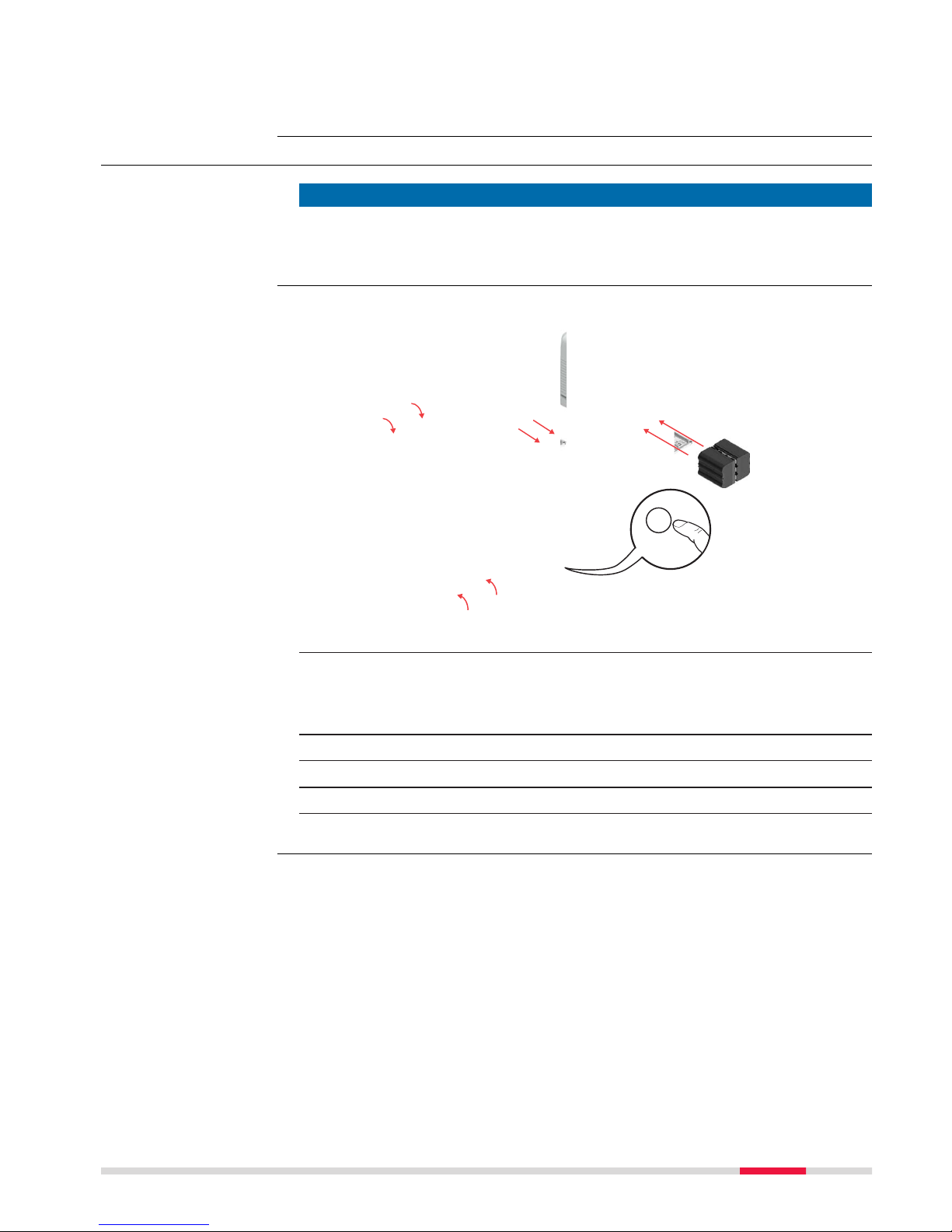
16468_002
4
2
3
4
1
1. Open the USB compartment at the bottom of the instrument.
2. To insert the MS256 USB stick, hold the stick with the Leica logo fac-
ing t
o the right.
Slide it into the USB port until it clicks into position.
☞
Do not force the USB stick into the port.
3. To remove the MS256 USB stick, slide the stick out of the USB port.
4. Close the USB compartment.
32 Operation

5 Care and Transport
5.1 Transport
When transporting the equipment in the field, always make sure that you:
•
either car
ry the product in its original container,
•
or in the backpack,
•
or carry the tripod with its legs splayed across your shoulder, keeping the
attached product upright.
Never carry the product loose in a road vehicle, as it can be affected by shock
and vib
ration. Always carry the product in its container and secure it.
For products for which no container is available use the original packaging or
its equivalent.
When transporting the product by rail, air or sea, always use the complete original Leica G
eosystems packaging, container and cardboard box, or its equiva-
lent, to protect against shock and vibration.
When transporting or shipping batteries, the person responsible for the produc
t must ensure that the applicable national and international rules and regulations are observed. Before transportation or shipping, contact your local passenger or freight transport company.
5.2 Field Check
For units that are exposed to high mechanical forces, for example through frequen
t transport or rough handling or for units stored for a long period, it is
recommended to carry out test measurements periodically.
5.3 Storage
Respect the temperature limits when storing the equipment, particularly in
summer if the equip
ment is inside a vehicle. Refer to "6 Technical Data" for
information about temperature limits.
•
R
efer to "Environmental Specifications" for information about storage tem-
perature range.
•
Remove batteries from the product and the charger before storing.
•
After storage recharge batteries before using.
•
Protect batteries from damp and wetness. Wet or damp batteries must be
dried before storing or use.
•
A storage temperature range of 0°C to +30°C/+32°F to 86°F in a dry environment is recommended to minimise self-discharging of the battery.
•
At the recommended storage temperature range, batteries containing a
40% to 50% charge can be stored for up to one year. After this storage
period the batteries must be recharged.
Transport in the field
Transport in a road
vehic
le
Shipping
Shipping, transport of
batteries
☞
Product
Care and Transport 33

5.4 Cleaning and Drying
•
N
ever touch the glass and scanning mirror with your fingers.
•
Use only a clean, soft, lint-free cloth for cleaning. If necessary, moisten the
cloth with water or pure alcohol. Do not use other liquids; these may
attack the polymer components.
Dry the product, the backpack, the transport container, the foam inserts and
the ac
cessories at a temperature not higher than 40 °C /104 °F and clean
them. Open the battery cover and dry the battery compartment. Do not repack
until everything is completely dry. Always close the container or backpack when
using in the field.
Use only a clean, soft, lint-free cloth for cleaning.
Keep plugs clean and dry. Blow away any dirt lodged in the plugs of the connec
ting cables.
5.5 Glass Cleaning Procedure
The scanning window must be kept clean. The instructions must be followed as
de
scribed in this chapter to clean the scanner window.
CAUTION
Before any cleaning procedure, ensure that the instrument is switched off and
the ba
ttery has been removed.
Using only a compressed gas duster to remove dust and debris from surface of
s
canner window.
☞
Never rub off dust or debris as this will scratch the glass and so possibl
y cause permanent damage to the special optical coatings.
Soiling of the glass pane can cause extreme measurement errors and therefore
us
eless data!
☞
All soiling that is visible on the glass pane has to be removed, except
for single small dust particles that adhere inevitably.
For the glass cleaning procedure, the Leica cleaning tissue provided with the
sys
tem is recommended.
Housing parts of
pr
oduct and accesso-
ries
Damp products
Charger and AC/DC
p
ower supply
Cables and plugs
General cleaning
inf
ormation
Dust and debris on
op
tical surfaces
Cleaning of optical
sur
faces
34 Care and Transport

Clean the glass pane regularly with the recommended cleaning tissue:
•
Swit
ch off instrument and remove the battery.
•
Washing hands is necessary in order to avoid grease on the cleaning tissue.
•
Better, use gloves to avoid finger oil on the glass.
•
Then use the Leica cleaning tissue.
•
If any smears from cleaning are visible against back light, repeat the procedure.
•
Do not use air from the pneumatic power system as this is always slightly
oily!
Care and Transport 35

6 Technical Data
6.1 General Technical Data of the Product
For details regarding the charging station refer to GKL341 User Manual.
Function Component
Internal storage Removable 256 GB USB 3.0 memory device.
235 G
B effective, exFAT formatted.
Communication Integrated 802.11 a/b/g/n WLAN.
The RTC360 has three integrated HDR digital cameras.
Camera data Value
Type Colour sensor, fixed focal length
Single image 4000 x 3000 pixels, 62° x 48° (V x Hz)
Full dome 36 images, automatically spatially rectified, 432 Mpx
r
aw data, 360° x 300°
180 Mpx on point cloud with 3 mm resolution
White balancing Automatic
HDR Automatic, 5 brackets
Minimum range 0.5 m
The RTC360 is a multi-sensor system equipped with various integrated sensors
t
o allow for automated online registration in the field.
Sensor Description
Visual inertial system VIS
Video enhanced inertial measuring system to track
mov
ement of the scanner position relative to the
previous setup in real-time.
Tilt IMU-based.
Accuracy: 3' for any tilt.
Altimeter Electronic barometer to detect the difference in ele-
vation relative to a reference elevation.
Compass Electronic compass to deliver the orientation of the
instrument.
GNSS Onboard GNSS receiver to calculate the position of
the instrument.
6.2 System Performance
☞
All accuracy specifications are on a level of confidence of 68% according t
o the Guide of the Expression of Uncertainty in Measurement
(JCGM100:2008).
Angle accuracy of single measurement
Accuracy (horizontal/vertical)
18"/18"
☞
Storage and communic
ation
Internal HDR cameras
Additional internal
senso
rs
System performance
an
d accuracy
36 Technical Data

3D point accuracy of single measurement
Albedo Distance [m]
5 10 20 40 60
White 89% 1.4 mm 1.9 mm 2.9 mm 5.3 mm 7.8 mm
Grey 21% 1.5 mm 2.0 mm 3.2 mm 5.7 mm 8.2 mm
Black 8% 1.6 mm 2.2 mm 3.4 mm 6.1 mm 8.8 mm
6.3 Laser System Performance
☞
The scanning system is a high speed time-of-flight unit, enhanced by
W
aveform Digitising (WFD) technology with a maximum scan rate of
2.000.000 points/second.
Laser unit:
Scanning laser Value
Classification Laser Class 1 (in accordance with IEC 60825‑1
(2014‑05))
Wavelength 1550 nm (invisible)
Range:
Scanning data Value
Beam divergence 0.5 mrad (1/e2, full angle)
Beam diameter at
f
ront window
6 mm (1/e2)
Minimum range 0.3 m
Maximum range 130 m @ 89% albedo
Range accuracy 1.0 mm +10 ppm from 0.5 m to 130 m
Range noise of single measurement:
Albedo Distance [m]
5 10 20 40 60
White 89% 0.3 mm 0.4 mm 0.5 mm 0.6 mm 1.0 mm
Grey 21% 0.4 mm 0.5 mm 0.6 mm 0.8 mm 2.0 mm
Black 8% 0.5 mm 0.6 mm 0.7 mm 2.5 mm 5.0 mm
Field-of-View (per scan):
Field-of-View Value
Selection Always full dome.
Horizontal 360°
Vertical 300°
Scanning optics Vertically rotating mirror on horizontally rotating
bas
e.
Laser scanning
sys
tem data
Technical Data 37

Maximum range for 3 settings:
Point density mode Resolution
[mm @ 10m]
Maximum range
[m]
Low 12 130
Medium 6 130
High density 3 65
Scan duration for 3 settings:
Point density mode Resolution
[mm @ 10m]
Estimated scan
dura
tion [MM:SS] for a
full dome scan
Low 12 00:25
Medium 6 00:50
High density 3 01:40
Image capturing time:
Camera type Estimated image duration [MM:SS]
HDR 01:00
Scan size for 3 settings:
Resolution
[mm @ 10m]
Approx. scan
si
ze
[Points Hz x V]
Scan without
colour
[MB]
Scan with colour
[MB]
Low 2083 x 5084 ~183 ~1678
Medium 4166 x 10168 ~732 ~2228
High density 8333 x 20334 ~2913 ~4396
6.4 Electrical Data
Power supply:
Exchangeable battery
11.1V DC; Two exchangeable GEB361 batteries needed for operation.
Power consumption:
Instrument
30 W typical; 75 W max.
Supply Value
Type Li-Ion
Voltage 11.1 V
Capacity 5.6 Ah
RTC360 power supply
an
d consumption
GEB361 exchangeable
ba
ttery
38 Technical Data

Exchangeable
ba
ttery
Value
Operating time up to 60 setups per battery set, typical continuous
use:
•
at room temperature,
•
with medium resolution and
•
with Imaging/VIS enabled.
Charging time Typical charging time with charger GKL341 is 4-8
hours at room temperature.
•
1-2 batteries: up to 4 h
•
3-4 batteries: up to 8 h
Mode Value
Input 100 -240 V AC, 50-60 Hz, 2.0 A
Output 24 V DC, 6.25 A, 150 W
6.4.1 Pin Assignment of Lemo Ports
Lemo1, 8 pin female
010743_001
1
2
3
45
6
7
8
Pin Name
1 D1+
2 D1-
3 D2+
4 D2-
5 D3+
6 D3-
7 D4+
8 D4-
Lemo1, 5 pin female
010744_001
1
2
3
5
4
Battery operating and
c
harging times
GEV282 AC/DC power
supply
Ethernet port - for
service purposes only
Power supply port
Technical Data 39

Pin Name Function
1 PWR_IN Power-In, 24 V
2 NC Do not connect
3 GND Ground
4 GND Ground
5 PWR_IN Power-In, 24 V
6.5 Environmental Specifications
6.5.1 RTC360
Temperature range:
Type Operating temperature
[°C]
Storage temperature
[°C]
RTC360 -5 to +40 -40 to +70
Protection against water, dust and sand:
Type Protection
RTC360 IP54 (IEC 60529), upright ±15 °/
upside down ±15 °
•
Dus
t protected
•
Protection against splashing water from any
direction
IP51 (IEC60529), in any other position
•
Dust protected
•
Protection against dripping water
Humidity:
Type Protection
RTC360 Max 95 % non condensing
Lighting:
Type Conditions
RTC360 Fully operational from bright sunlight to complete
dar
kness.
6.5.2 GEB361 Battery and GEV282 AC/DC Power Supply
Temperature range
Temperature GEB361 battery GEV282 AC/DC
p
ower supply
Operating Temperature Charging:
0 °C to +45 °C
Discharging:
-20 °C to +60 °C
0 °C to 40 °C
Storage Temperature -40 °C to +70 °C -10 °C to 80 °C
Environmental specific
ations RTC360
Environmental specific
ations
40 Technical Data

Protection against water, dust, sand and humidity
Type Protection
GEB361 battery IP54 (IEC 60529)
Dust protected
Protection against splashing water from any direction.
Humidity max. 95% no
n condensing.
GEV282 AC/DC
power supply
Only operate in dry environments, for example in buildings and vehicles.
6.6 Dimensions
Part Dimensions [mm]
(D x W x H)
Dimensions [″]
(D x W x H)
RTC360 laser scanner 120 x 240 x 230 4.7 x 9.4 x 9.1
GEV282 AC/DC power
sup
ply
2.5 x 72.2 x 42.0 0.1 x 2.8 x 1.7
GEB361 battery 60 x 72 x 31 2.4 x 2.8 x 1.2
GVP730 transport
container
257 x 537 x 383 10.1 x 21.1 x 15.1
GVP736 backpack 200 x 350 x 460 7.9 x 13.8 x 18.1
Part Dimensions [mm]
(Diam
eter)
Dimensions [″]
(Diameter)
GAD120 tribrach
adapter
104.5 x 81.2 4.1 x 3.2
GAD121 adapter
plate for flexible
mounting
145 x 35 5.7 x 1.4
GAD122 adapter to
mount a RTC360 on
top of a Leica tripod
104.5 x 40 4.1 x 1.6
Dimensions
Technical Data 41

RTC360 laser scanner:
0016234_001
230
240 120
GAD120 tribrach adapter:
0016236_002
81.2
104.5
36_00
2
GAD121 adapter plate for flexible mounting:
0016237_001
35
145
37_001
42 Technical Data

GAD122 adapter to mount a RTC360 on top of a Leica tripod:
0016830_001
17
40
104.5
6.7 Weight
Part Weight [kg] Weight [lbs]
RTC360 laser scanner 5.3 nominal 11.7 nominal
GEV282 AC/DC power
sup
ply
0.86 1.9
GEB361 battery 0.34 0.7
RTC360 transport
container (without
scanner and accessories)
3.67 8.1
GVP736 backpack 1.79 3.9
GAD120 tribrach
adapter
0.43 0.9
GAD121 adapter
plate for flexible
mounting
0.85 1.9
6.8 Accessories
Included standard accessories:
•
R
TC360 transport container
•
GEV282 AC/DC power supply
•
GKL341, Multicharger Professional 5000
•
Battery GEB361, 4x
•
RTC360 USB Flash Drive - 256 GB, 2x
•
RTC360 Rain cover
•
RTC360 Quick guide
•
RTC360 System USB card
•
Cleaning tissue
•
12 month warranty
•
Calibration certificate digital access via online registration
•
Additio
nal batteries GEB361
•
RTC360 lightweight tripod GST80
•
RTC360 tribrach adapter GAD120
•
RTC360 adapter plate for flexible mounting GAD121
•
Adapter to mount a RTC360 on top of a Leica tripod GAD122
•
RTC360 backpack GVP730
•
Range of Customer Care Products (CCP) that include support and hardware.
Weight
Scope of delivery
Additional
accessories
Technical Data 43

6.9 Conformity to National Regulations
6.9.1 RTC360
•
F
CC Part 15 (applicable in US)
•
Hereby, Leica Geosystems AG declares that the radio equipment type
RTC360 is in compliance with Directive 2014/53/EU and other applicable
European Directives.
The full text of the EU declaration of conformity is available at the following Internet address: http://www.leica-geosystems.com/ce.
Class 1 equipment according to European Directive 2014/53/EU
(RED) can b
e placed on the market and be put into service with-
out restrictions in any EEA member state.
•
T
he conformity for countries with other national regulations not covered
by the FCC part 15 or European Directive 2014/53/EU has to be approved
prior to use and operation.
•
Japanese Radio Law.
•
This device is granted pursuant to the Japanese Radio Law (
電波法
).
•
T
his device should not be modified (otherwise the granted designa-
tion number will become invalid).
Type Frequency band [MHz]
WLAN 2400 - 2483.5
Type Output power [mW]
WLAN 2.4 GHz: max. 80 mW, at each of 2 antenna
channels
Type Antenna Gain [dBi]
WLAN Integrated antennas, 2x2
M
IMO
2.4 GHz: 0 dBi
6.9.2 Dangerous Goods Regulations
Many products of Leica Geosystems are powered by Lithium batteries.
Lithium ba
tteries can be dangerous under certain conditions and can pose a
safety hazard. In certain conditions, Lithium batteries can overheat and ignite.
☞
When carrying or shipping your Leica product with Lithium batteries
onboard a commercial aircraft, you must do so in accordance with the
IATA Dangerous Goods Regulations.
☞
Leica Geosystems has developed G
uidelines on “How to carry Leica
products” and “How to ship Leica products” with Lithium batteries.
Before any transportation of a Leica product, we ask you to consult
these guidelines on our web page
(http://www.leica-geosystems.com/dgr) to ensure that you are in
accordance with the IATA Dangerous Goods Regulations and that the
Leica products can be transported correctly.
Conformity to
na
tional regulations
Frequency band
Output power
Antenna
Dangerous Goods
R
egulations
44 Technical Data

☞
Damaged or defective batteries are prohibited from being carried or
tr
ansported onboard any aircraft. Therefore, ensure that the condition
of any battery is safe for transportation.
Technical Data 45

7 Software Licence Agreement
This product contains software that is preinstalled on the product, or that is
sup
plied to you on a data carrier medium, or that can be downloaded by you
online according to prior authorisation from Leica Geosystems. Such software is
protected by copyright and other laws and its use is defined and regulated by
the Leica Geosystems Software Licence Agreement, which covers aspects such
as, but not limited to, Scope of the Licence, Warranty, Intellectual Property
Rights, Limitation of Liability, Exclusion of other Assurances, Governing Law
and Place of Jurisdiction. Please make sure, that at any time you fully comply
with the terms and conditions of the Leica Geosystems Software Licence
Agreement.
Such agreement is provided together with all products and can also be referred
to and downloaded at the Leica Geosystems home page at
http://leica-geosystems.com/about-us/compliance-standards/legal-documents
or collected from your Leica Geosystems distributor.
You must not install or use the software unless you have read and accepted
the terms and conditions of the Leica Geosystems Software Licence Agreement. Installation or use of the software or any part thereof, is deemed to be
an acceptance of all the terms and conditions of such Licence Agreement. If
you do not agree to all or some of the terms of such Licence Agreement, you
must not download, install or use the software and you must return the
unused software together with its accompanying documentation and the purchase receipt to the distributor from whom you purchased the product within
ten (10) days of purchase to obtain a full refund of the purchase price.
The software on the product may contain copyright-protected software that is
lic
ensed under various open source licences.
Copies of the corresponding licences:
•
ar
e provided together with the product (for example in the About panel of
the software).
•
can be downloaded on http://opensource.leica-geosystems.com.
If foreseen in the corresponding open source licence, you may obtain the corr
esponding source code and other related data on http://opensource.leica-geosystems.com. Contact opensource@leica-geosystems.com in case you need
additional information.
Software Licence
Agr
eement
Open source information
46 Software Licence Agreement


Leica Geosystems AG
Heinrich-Wild-Strasse
CH-9435 Heerbrugg
Switzerland
Phone +41 71 727 31 31
www.leica-geosystems.com
870891-1.0.0en
Or
iginal text (870891-1.0.0en)
Printed in Switzerland
© 2018 Leica Geosystems AG, Heerbrugg, Switzerland
 Loading...