

Page 1
Leica mojoXact Plus
User Manual
Version 1.0
English
Page 2
Introduction
Purchase Congratulations on the purchase of a Leica mojoXact Plus.
This manual contains important safety directions as well as instructions for installing
the product and operating it. For safety information, refer to Chapter "13 Safety
Directions".
If your Leica mojoXact Plus is connecting to a Leica mojo3D, read carefully through
this User Manual and the Leica mojo3D User Manual, before you switch on the
product. If your Leica mojoXact Plus is connecting to a third party terminal that is
ISOBUS Universal Terminal compliant, read carefully through this User Manual and the
terminal’s supporting documentation before you switch on the product.
The Leica mojoXact Plus is to be used solely in combination with Leica Geosystems’
guidance systems. Therefore it is mandatory to also observe the directions and
instructions contained in the Leica guidance product manual.
To ensure safety when using the system, please also observe the directions and
instructions contained in the User Manual and Safety Handbook issued by the agricultural machinery manufacturer.
Product identification
Symbols used in
this manual
Trademarks GL1DETM is the property of NovAtel Inc.
The type and serial number of your product are indicated on the type plate (located
on the bottom of the product). Enter the type and serial number in the spaces below
and always refer to this information when you need to contact your agency or Leica
Geosystems authorised service workshop.
Type: _______________________________________
Serial No.: _______________________________________
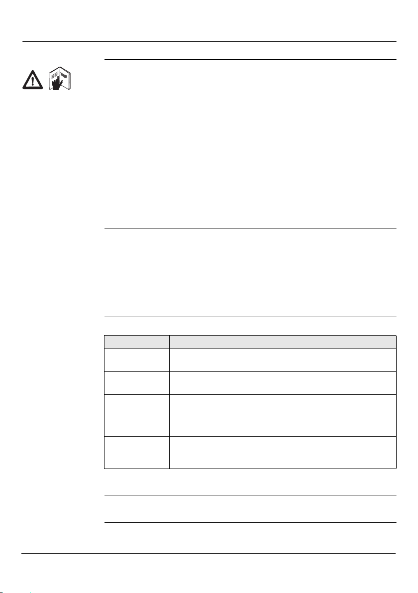
The symbols used in this manual have the following meanings.
Type Description
DANGER Indicates an imminently hazardous situation which, if not
WARNING Indicates a potentially hazardous situation or an unintended use
CAUTION Indicates a potentially hazardous situation or an unintended use
Note - the absence of specific alerts does not mean that there are no safety risks
involved.
All other trademarks are the property of their respective owners.
avoided, will result in death or serious injury.
which, if not avoided, could result in death or serious injury.
which, if not avoided, may result in minor or moderate injury,
and/or appreciable material, financial and environmental
damage, or all of these.
Important paragraphs which must be adhered to in practice as
they enable the product to be used in a technically correct and
efficient manner.
2 Introduction, Leica mojoXact Plus
Page 3
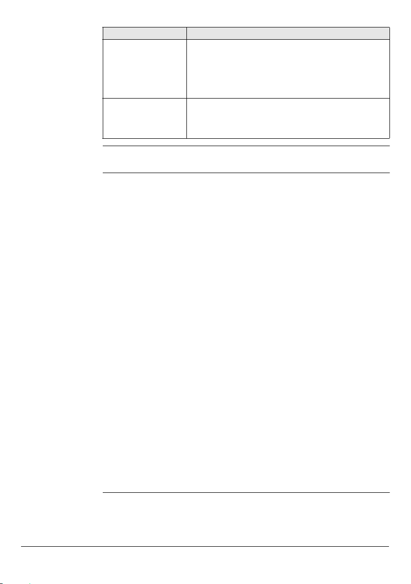
Available
documentation
Document Name Description
Leica mojoXact Plus
User Manual
Leica mojo3D
User Manual
This manual. All instructions required in order to operate
the mojoXact Plus product when it is connected to a Leica
mojo3D or a third party terminal that is ISOBUS Universal
Terminal compliant, to a basic level are contained in this
User Manual. It provides an overview of the system
together with technical data and safety directions.
All instructions required in order to operate the mojo3D
product to a basic level are contained in its User Manual. It
provides an overview of the system together with technical
data and safety directions.
Process for setting
up the
mojoXact Plus to
auto-steer
The images in this manual are for reference purposes only. Individual screens and
icons may differ from the actual items.
From when the customer receives their mojoXact Plus to having it auto-steer the
vehicle, the following steps need to occur:
1. Unpack your mojoXact Plus and ensure that all components are included (refer
to Section "1.2 Components of the mojoXact Plus System"), and that any other
components required, such as an ISO UT cable and external CDMA modem are
also present.
2. Read this manual, the Leica mojoXact Plus User Manual.
3. Install the mojoXact Plus system following the instructions in Chapter "2 System
Installation".
4. Power up the mojoXact Plus (refer to Section "3.1 Starting Up").
If the mojoXact Plus is connected to a third-party terminal, complete the following
steps:
1. Unlock the universal terminal features of the mojoXact Plus (refer to Section "3.2
Universal Terminal Unlock Code").
2. Step through the initial setup wizard supplying the information that is asked for
(refer to Section "3.3 Initial Setup Wizard").
3. Select and configure the steer kit (refer to Section "5.2 Steer Kit Selection and
Setup").
4. Test the auto-steer settings (refer to Section "5.6 Testing Auto-Steer").
5. If the vehicle has an implement attached to it, configure the implement settings
(refer to Section "4.3 Implement Setup").
6. Configure the correction source (refer to Chapter "6 Correction Sources").
7. Set a wayline (refer to Chapter "7 Guidance").
8. Ensure all auto-steer engage criteria are met (refer to Section "5.1 Engage AutoSteer").
9. Engage auto-steer (refer to Section "5.1 Engage Auto-Steer").
If the mojoXact Plus is connected to a Leica mojo3D, refer to the Leica mojo3D User
Manual for instructions on setting up your system to auto-steer.
Leica mojoXact Plus, Introduction 3
Page 4

Table of Contents
In this manual Chapter Page
1 System Overview 8
1.1 General mojoXact Plus System Information 8
1.2 Components of the mojoXact Plus System 8
1.3 Features 9
1.3.1 mojoXact Plus Hardware 9
1.3.2 mojoXact Plus Software 9
1.3.3 mojoXact Plus Positioning 9
1.3.4 mojoXact Plus Guidance 10
1.4 Audience 10
2 System Installation 12
2.1 Before Installation 12
2.2 GPS Antenna Installation 13
2.3 Cell Modem Antenna and Bracket 15
2.4 SIM Card Installation 15
2.5 mojoXact Plus Installation 16
2.6 CAN Port Connection Changes 19
3 Running the mojoXact Plus for the First Time 20
3.1 Starting Up 20
3.2 Universal Terminal Unlock Code 20
3.3 Initial Setup Wizard 22
3.4 Main Navigation Screen 29
3.5 Running the Setup Wizard at any Time 31
3.6 Changing System Settings 31
3.6.1 Changing Region Settings 32
3.6.2 Cell Modem Settings 32
3.7 Feature Unlock 35
4 Vehicles and Implements 38
4.1 Vehicle Measurement Setup 38
4.2 Terrain Compensation 40
4.3 Implement Setup 46
5 Auto-Steer 48
5.1 Engage Auto-Steer 48
5.1.1 Roading Safety Feature 48
5.1.2 Preconditions to Engage Auto-steer 49
5.1.3 Engage Auto-steer 49
5.1.4 Disengage Auto-steer 50
5.2 Steer Kit Selection and Setup 50
5.2.1 Troubleshooting Steer Kit and CAN Bus Problems 57
5.3 Steer Kit Status 57
5.4 Steer Kit Calibration 58
5.4.1 Stationary Engage and Reverse Steering 62
5.5 Tuning Auto-Steer Performance 63
5.5.1 Tuning Procedure 63
5.5.2 Sensitivity 64
5.5.3 Aggressiveness 65
5.5.4 Overshoot 66
4 Table of Contents, Leica mojoXact Plus
Page 5

5.5.5 Speed Adjust 66
5.5.6 Tuning Tips 67
5.6 Testing Auto-Steer 68
5.6.1 Troubleshooting Steering Test Issues 72
6 Correction Sources 74
6.1 GL1DE 74
6.2 Network RTK 77
6.3 Internal Radio (RTK Base Station) 82
6.4 External Radio 85
6.5 Correction Source Status 88
7 Guidance 90
7.1 AB Parallel Guidance 90
7.2 A+ Heading Guidance 92
7.3 Pivot Guidance 94
7.4 Wayline Management 96
7.4.1 Saving the Active Wayline 96
7.4.2 Loading a Saved Wayline 97
7.4.3 Changing the Name of a Wayline 98
7.4.4 Deleting a Wayline 98
7.4.5 Deleting All Waylines 99
7.4.6 Exporting Waylines 100
7.4.7 Importing Waylines 101
7.5 Field Offset 103
7.6 Nudge 104
8 NMEA Output 106
8.1 Configuring NMEA Output 107
8.1.1 NMEA 0183 Setup 107
8.1.2 Logging NMEA 0183 Data to USB 110
8.1.3 NMEA 2000 Setup 112
9 System Information and Errors 114
9.1 Status Information 114
9.2 Position Information 116
9.3 Correction Source Status 117
9.4 Device Information 119
9.5 Cell Modem Status 120
9.6 Error Notifications 121
10 Virtual Wrench Remote Service 124
10.1 Connecting to Virtual Wrench 125
10.2 Disconnecting from Virtual Wrench 126
11 Software Maintenance 128
11.1 Upgrading Software from Virtual Wrench 128
11.2 Upgrading Software from a USB Memory Key 130
11.3 Backing Up Current Software 132
11.4 Restoring the Previous Software Version 133
Leica mojoXact Plus, Table of Contents 5
Page 6

12 Care and Transport 136
12.1 Transport 136
12.2 Storage 136
12.3 Cleaning and Drying 136
13 Safety Directions 138
13.1 General Introduction 138
13.2 Intended Use 138
13.3 Limits of Use 139
13.4 Responsibilities 139
13.5 Hazards of Use 139
13.6 Electromagnetic Compatibility (EMC) 142
13.7 FCC Statement, Applicable in U.S. 143
13.8 ICES-003 Statement, Applicable in Canada 143
13.9 Labelling 144
14 Technical Data 146
14.1 mojoXact Plus Technical Data 146
14.2 mojoXact Plus GPS Receiver Technical Data 147
14.3 Wireless Module Technical Data 148
14.3.1 HSDPA Wireless Module Technical Data 148
14.4 Antennas Technical Data 148
14.4.1 Cellular Antenna Technical Data 148
14.4.2 Red GPS Antenna Technical Data 148
14.5 Conformity to National Regulations 150
14.5.1 mojoXact Plus 150
15 International Limited Warranty, Software License Agreement 152
Appendix A Redeeming a System Option Voucher 154
Appendix B Formatting USB Memory Keys 156
Appendix C GNU General Public License 160
Appendix D Glossary of Terms 162
6 Table of Contents, Leica mojoXact Plus
Page 7

Leica mojoXact Plus, Table of Contents 7
Page 8
1 System Overview
This chapter describes the major functionality offered by the mojoXact Plus, its
components, hardware, software, positioning and guidance features, and this user
manual’s intended audience.
1.1 General mojoXact Plus System Information
General information
Leica Geosystems’ mojoXact Plus is a GPS-based agricultural guidance system. It
connects to Leica’s mojo3D product or third party terminals that are ISOBUS Universal
Terminal compliant to provide:
• RTK positioning;
• advanced hydraulic steering kit options;
• visual guidance;
• auto-steering; and
• remote service, diagnostics and software upgrades via Virtual WrenchTM, thus
reducing costly onsite service calls.
The mojoXact Plus uses a single dual band antenna for GPS and a cell antenna. For
GPS, only the red GPS antenna is required to be mounted on the roof of the vehicle.
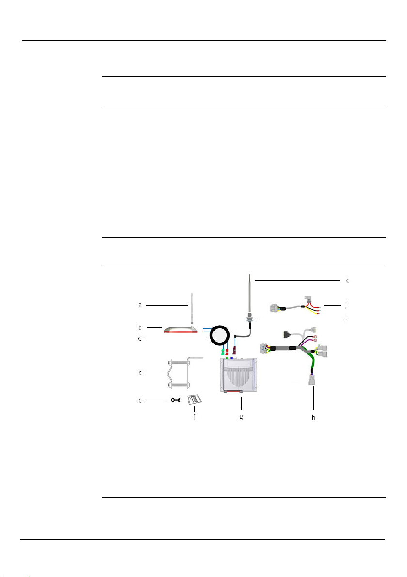
1.2 Components of the mojoXact Plus System
mojoXact Plus
components
a) GPS (Radio) whip antenna g) mojoXact Plus
b) GPS (Red) antenna h) mojoXact port expansion cable
c) Twin RF cable (L1/L2 Radio) i) Single RF cable (cell)
d) Antenna mounting bracket j) Power cable
e) Spanner k) Cell antenna
f) Cleaning wipes
8 System Overview, Leica mojoXact Plus
Page 9
Accessories
required
For a connection to a Leica mojo3D, the following accessories are required:
• Leica mojo3D port expansion cable
For a connection to a third party terminal that is ISOBUS Universal Terminal
compliant, the following accessories are required:
• ISO UT cable (compatible with the third party terminal)
The GPS antenna supplied with the Leica mojo3D is not required when
operating with a Leica mojoXact Plus.
1.3 Features
1.3.1 mojoXact Plus Hardware
mojoXact Plus
hardware features
a
b
c
• Simple installation and color-coded quick-install antennas.
• Integrated L1/L2 GPS receiver.
• Integrated HSPA cell modem.
• 12 volt operation.
• Internal storage for waylines and settings.
1.3.2 mojoXact Plus Software
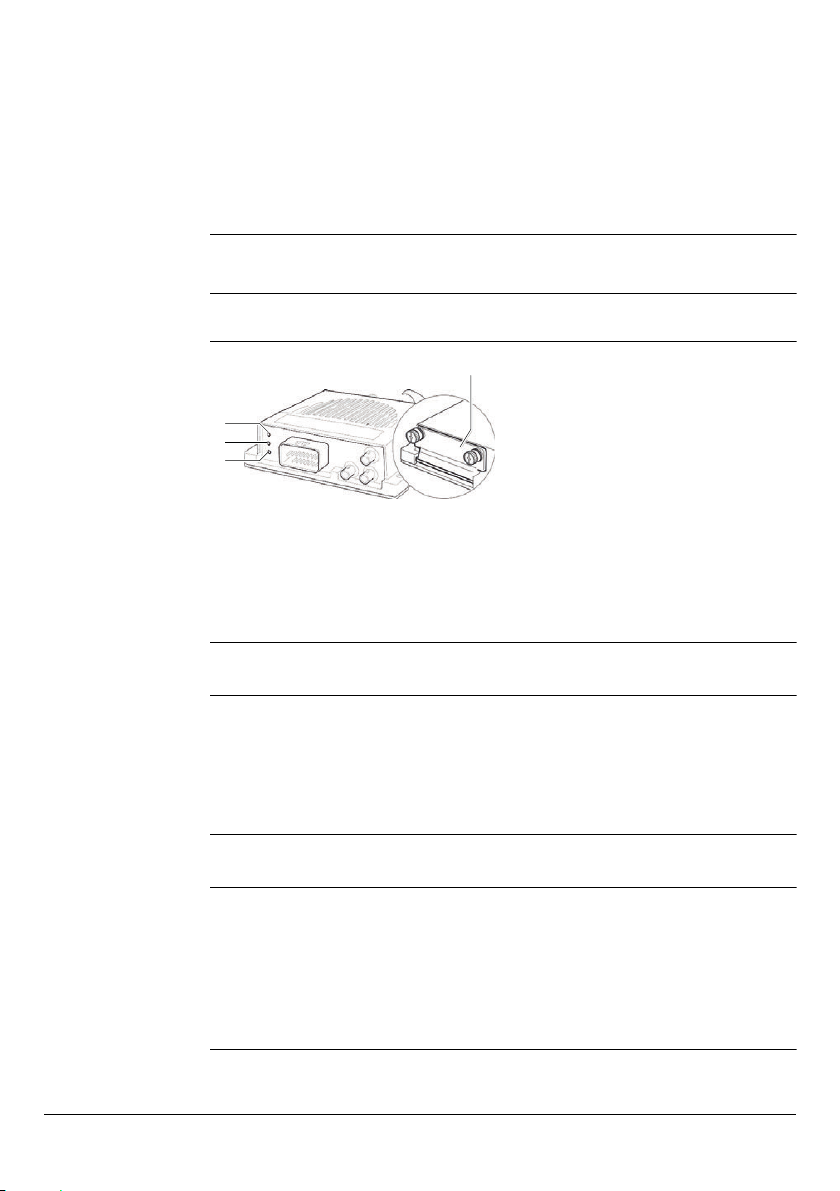
a) Green LED - lights when a display is
d
connected.
b) Orange LED - lights when an error is
active.
c) Red LED - lights when the
mojoXact Plus has power.
d) USB/SIM port - data transfer and
cell modem SIM port.
mojoXact Plus
software features
• Intuitive software that allows for easy setup and use.
• On screen field guidance.
• Auto-steer compatible.
• Upgrade, backup, and rollback of software through the USB interface.
• Virtual Wrench™, which provides remote support and over-the-air software
upgrades.
1.3.3 mojoXact Plus Positioning
mojoXact Plus
positioning
features
Leica mojoXact Plus, System Overview 9
• GPS algorithms are tuned for the agricultural environment.
• Optional NMEA (NMEA 0183, NMEA 2000) output for auxiliary devices that
require GPS data.
• Optional Radar-out signal for auxiliary devices that require a radar speed signal.
• Advanced 3-axis terrain compensation.
• Compatible with the following correction sources: base station RTK, Network
RTK, external radio and Dual Frequency GL1DETM.
Page 10

1.3.4 mojoXact Plus Guidance
mojoXact Plus
guidance features
• Multiple guidance patterns for visual guidance, including AB Parallel, A+ Heading
and Pivot.
• On-screen lightbar with heading assist operation.
• Electric auto-steer capable, with Electric Steer Kit.
• Auto-steer ready capable.
1.4 Audience
Intended audience
and assumptions
Third party
terminal user interfaces
This user manual is intended for operators of agricultural machinery that is to be
guided by a mojoXact Plus, and technicians responsible for the installation of
mojoXact Plus systems.
For operators of agricultural machinery, no prior knowledge of agricultural guidance
systems is assumed.
If the mojoXact Plus is installed for use with a third party terminal, the third party
terminal’s user documentation should be referred to for instructions on how to:
• select buttons or fields;
• select an item from a list; and
• enter and accept values.
10 System Overview, Leica mojoXact Plus
Page 11

Leica mojoXact Plus, System Overview 11
Page 12

2 System Installation
2.1 Before Installation
General installation information
mojoXact Plus
installation
process
• The following instructions are to be used as a general guide during the installa-
• The system will not operate at peak performance if steering joints and linkage
• Install the system in a clean and dry workshop environment. Failure to do so may
• Route and secure all cables and wiring to ensure that they do not chafe or rub,
• The average installation time will vary, but it should be approximately two to four
The main steps involved in installing a mojoXact Plus system are:
• Read the documentation.
• Install the GPS Antenna.
• Install the Cell Modem Antenna (if applicable).
• Install the SIM Card in the mojoXact Plus (if applicable).
• Install the mojoXact Plus.
• Connect all cables.
• Route and secure cables to ensure the work environment is safe and so there is
The installer must read and study this user manual, including the safety
directions (refer to Chapter "13 Safety Directions"). The installer must be
able to use the system in accordance with this user manual. Leica Geosystems recommends that installation of the mojoXact Plus equipment be
performed by a qualified technician, as installation does require making
electrical connections.
tion of the Leica mojoXact Plus. For more specific instructions, please visit
www.virtualwrench.com to view additional platform information and recommended vehicle settings.
assemblies are not within the manufacturer's specifications. Check for worn
steering components by turning the steering wheel. As the steering wheel is
turned, the wheels should begin to move. If results are unsatisfactory, please
consult your vehicle manufacturer’s maintenance manual.
result in electrical short-circuits or other product malfunctions. Any moisture on
the roof of the vehicle will also prevent the antenna mounting tape from
sticking properly.
as this could cause premature failure.
hours per vehicle, but is dependent on vehicle type.
no chafing or rubbing.
These steps are explained in the sections below.
12 System Installation, Leica mojoXact Plus
Page 13
2.2 GPS Antenna Installation
Prepare the GPS
antenna
To prepare the GPS (Red) antenna for mounting on the vehicle’s roof, carry out the
following steps:
1. Clean the vehicle cab’s roof with Windex® glass cleaner or a similar product, to
prepare it for the installation of the antenna.
Start all antenna cable connections by hand before using the supplied
spanner to tighten. Do not over tighten the cable connectors. Run the
threads to the end by hand, and tighten only 1/8th turn more with the
spanner.
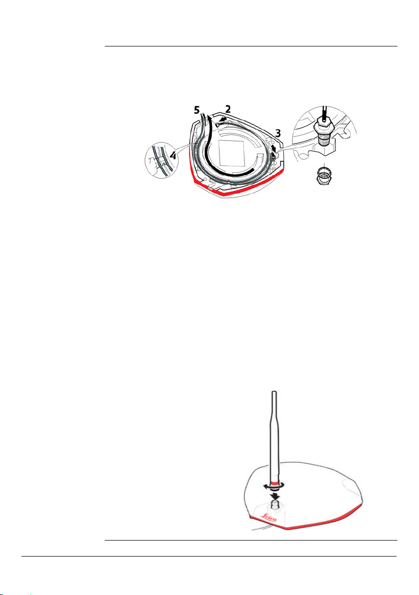
2. Take the Twin RF Cable and connect the small connector to the GPS antenna
(shown at location 2 in the picture above).
3. The other metal connector of the Twin RF Cable is for the whip antenna. Remove
the outer nut and washer from the connector. Insert the thread of the connector
as shown at location 3 and in the exploded view in the picture above, so the
thread is accessible from the top of the GPS antenna. Attach the washer and fix
with the nut.
4. Run the cables through the circular slot provided on the bottom side of the cover.
Align each cable with the slot and push it into the slot using the antenna cable
grommets and antenna cable supports provided.
5. You have several options for how you want the cables to exit the antenna cover.
Choose the option that works best for your application.
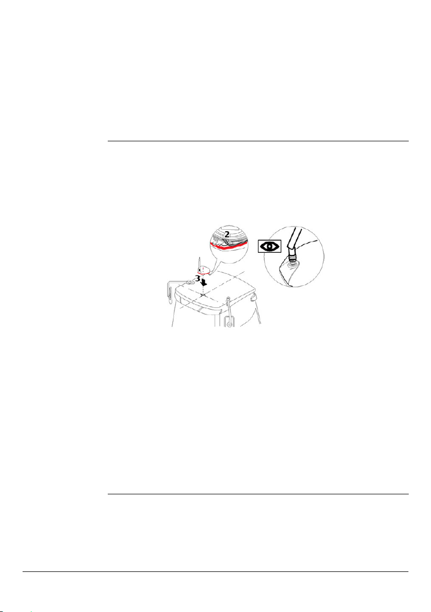
6. Install the whip antenna on the GPS
antenna by screwing it onto the
connector installed in Step 3
above.
Leica mojoXact Plus, System Installation 13
The whip antenna should be
mounted on the GPS antenna
so it will fold backwards if
needed when the GPS
antenna is mounted on the
vehicle.
Page 14
Position of the GPS
antenna
The GPS antenna should be mounted on the vehicle’s roof:
• on the center line of the vehicle’s wheel tracks if possible.
• as far forward as possible on the flat level part of the roof.
• not obstructed by exhausts, flashing lights or any other objects.
Find a location that is as close to the front of the vehicle as possible and centered
over the wheel tracks. Mark out this location on the roof of the vehicle.
Optional antenna adapter brackets are available - contact your Dealer for more information.
Mount the GPS
antenna
To mount the GPS antenna on the vehicle’s roof, carry out the following steps:
1. Use the supplied cleaning wipes to clean the installation area.
This is necessary even when the area has been cleaned with Windex® glass
cleaner (as instructed previously) to ensure that the installation area is as clean
as possible.
2. Remove the protective strip of the double-sided tape on the bottom of the GPS
antenna.
Be careful removing the backing tape (protective strip) from the sticking
blocks. Make sure that you peel off the backing tape and do not rip the
adhesive from the antenna.
3. Mount the GPS antenna on the vehicle’s roof.
The GPS antenna should mount with the whip antenna in the forward position.
The antenna must be mounted horizontally and not on an angle to ensure
the best possible signal reception.
The cables must not be cut, kinked or bent tightly, as their performance will
be degraded and system failure may result.
Cables should be routed neatly back to the mojoXact Plus.
14 System Installation, Leica mojoXact Plus
Page 15
2.3 Cell Modem Antenna and Bracket
2
A cell modem antenna and bracket is supplied as part of the mojoXact Plus kit.
mojoXact Plus with
a third party
terminal
mojoXact Plus with
a mojo3D
When using the mojoXact Plus with a third party terminal, the supplied cell modem
antenna needs to be mounted. A bracket is supplied to aid installation of the cell
modem antenna. Choose a location for the antenna where it will get good reception,
that is, away from obstructions, and where the cable can be neatly routed without
kinking or crushing it, to the mojoXact Plus.
When operating the mojoXact Plus with a Leica mojo3D, the cell modem antenna
must be connected to the mojo3D, not the mojoXact Plus. If the mojo3D’s original
cell modem antenna is not installed, install the mojoXact Plus’s cell modem antenna.
Choose a location for the antenna where it will get good reception, that is, away from
obstructions, and where the cable can be neatly routed without kinking or crushing
it, to the Leica mojo3D.
2.4 SIM Card Installation
When using the mojoXact Plus with a third party terminal, it is necessary to install the
SIM Card in the mojoXact Plus. The process for installing the SIM Card is detailed
below. If the mojoXact Plus is used with a Leica mojo3D, then the SIM Card is installed
in the mojo3D. Refer to the Leica mojo3D User Manual for installation instructions.
Installing the SIM
Card in the
mojoXact Plus
To install the SIM Card in the mojoXact Plus, carry out the following steps:
1. Carefully remove the mojoXact Plus
from its packaging and place it on a
workbench.
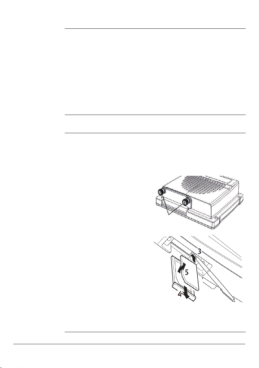
2. The SIM Card slot is at the front of
the mojoXact Plus. Unscrew the door
at the front (as shown at 2 in the
picture to the right) so it can open
and lie flat.
3. Use a pointed instrument to press
the release mechanism (as shown at
3 in the picture to the right), to
release the SIM Card holder.
4. Slide out the SIM Card holder (as
shown at 4 in the picture to the
right).
5. Place the SIM Card in the SIM Card
holder, with the chip facing up.
Ensure that the SIM Card is securely
seated in the holder.
6. Insert the SIM Card holder back into
the SIM Card slot and push it in so it
is secure in the mojoXact Plus.
7. Fold up the door and screw it in
place.
Leica mojoXact Plus, System Installation 15
Page 16

2.5 mojoXact Plus Installation
Before installation Before installing the Leica mojoXact Plus, it is recommended that you do the
mojoXact Plus
installation
following steps. For more information on each of these important steps, please refer
to the installation hints specific to your vehicle and Leica Steer Ready Kit.
1. Refer to any available installation hints specific to your vehicle type.
This information may be available from the website, www.virtualwrench.com, or
may have been supplied with your system. The method of completion of the
following tasks is determined by the make and model of your vehicle.
2. Check or prepare for the mojoXact Plus power connection.
If you are connecting a mojoXact Plus with a Leica mojo3D, check that you have
a mojoXact port expansion cable and a mojo3D port expansion cable.
If you are connecting a mojoXact Plus with a third party terminal, check that you
have a mojoXact port expansion cable and a power cable.
3. Install steering cable (CAN bus).
There are many possible combinations for this step, depending on vehicle type,
or the Leica Steer Ready Kit used, or both. The cable specific to your vehicle
should be purchased with your system.
NOTE: If you are upgrading from a mojoXact to a mojoXact Plus, verify the CAN port
that the Steer Kit must connect to, as this may have changed. Section "2.6 CAN Port
Connection Changes" provides information on the CAN port changes.
The mojoXact Plus can be mounted in any direction and there is no need to mount it
exactly flat. The mojoXact Plus should be mounted in a location so that:
• it does not obstruct the operation of the vehicle (such as the pedals).
• its front (where the USB port is accessed) is accessible.
• its rear is accessible to plug in and unplug cables.
To install the mojoXact Plus, carry out the following steps:
1. If the mojoXact Plus is still in its packaging, carefully remove it.
2. Using four screws and nuts, bolt the mojoXact Plus to a secure location.
3. Check that the mojoXact Plus is secure and cannot move.
If movement is possible then performance may be degraded.
16 System Installation, Leica mojoXact Plus
Page 17
Connecting the
a
b
c
d
e
f
g
h
mojoXact Plus to a
third-party
terminal
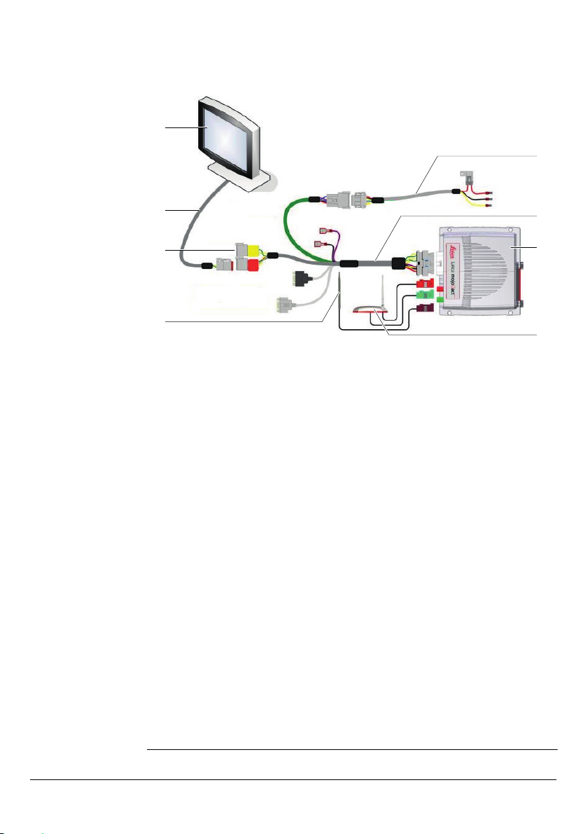
To connect the mojoXact Plus to a third party terminal that is ISOBUS Universal
Terminal compliant, refer to the picture below and carry out the following steps. The
following process assumes that the third party terminal has been installed in accordance with its documentation.
a) Third party terminal
b) ISO UT cable
c) Proprietary BUS for steering
d) Cell modem antenna
1. Connect the cell modem antenna cable (purple plug) to the purple antenna
socket on the back of the mojoXact Plus.
2. Connect the GPS antenna cables (green and red plugs) to the green and red
antenna sockets on the mojoXact Plus.
3. Connect the mojoXact port expansion cable to the mojoXact Plus.
4. Connect the green cable of the mojoXact port expansion cable to the power
cable.
5. Connect the ISO UT cable to the third party terminal and to the red CAN port of
the mojoXact port expansion cable. Note that on some vehicles, the UT and
steering bus are the same.
6. Connect the steering controller to the proprietary BUS for steering (yellow CAN
port of the mojoXact port expansion cable). Note that on some vehicles, the UT
and steering bus are the same.
7. Connect the power cable by connecting the red wire to a permanent 12V power
supply, the yellow wire to the vehicle’s switched ignition power and the green
wire to earth.
The mojoXact Plus is a 12-volt DC (negative-to-earth) system only.
8. Route and secure all cables and wiring to ensure that there is no chafing or
rubbing, that could cause premature failure.
For further information, refer to www.virtualwrench.com.
e) Power cable
f) mojoXact port expansion cable
g) mojoXact Plus
h) GPS antenna
Leica mojoXact Plus, System Installation 17
Page 18
Connecting the
mojoXact Plus to
the mojo3D
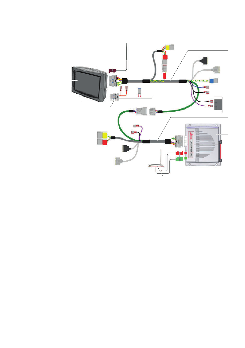
To connect the mojoXact Plus to a Leica mojo3D, refer to the picture below and carry
out the following steps. For more detailed information, refer to the Leica mojo3D
User Manual. The following process assumes that the mojo3D has been installed in
accordance with the instructions in the Leica mojo3D User Manual.
a
b
c
d
e
a) Cell modem antenna
b) mojo3D
c) Power cable
d) Proprietary BUS for steering
e) ISOBUS
1. If not already connected, connect the cell modem antenna cable (purple plug) to
the purple antenna socket on the back of the mojo3D.
2. Connect the GPS antenna cables (green and red plugs) to the green and red
antenna sockets on the mojoXact Plus.
3. Connect the mojo3D port expansion cable to the mojo3D.
4. Connect the mojoXact port expansion cable to the mojoXact Plus.
5. Connect the green cable of the mojo3D port expansion cable to the green cable
of the mojoXact port expansion cable.
6. Connect the power cable to the mojo3D and wire it to a reliable power source as
instructed in the Leica mojo3D User Manual.
7. Connect the steering controller to either the proprietary BUS for steering (yellow
CAN port of the mojoXact port expansion cable) or the ISOBUS (red CAN port of
the mojoXact port expansion cable) according to the table below in Section "2.6
CAN Port Connection Changes".
8. Ensure that any other required cables are connected correctly.
9. Route and secure all cables and wiring to ensure that there is no chafing or
rubbing, that could cause premature failure.
f) mojo3D port expansion cable
g) mojoXact port expansion cable
h) mojoXact Plus
i) GPS antenna
f
g
h
i
18 System Installation, Leica mojoXact Plus
Page 19
2.6 CAN Port Connection Changes
Overview If the mojoXact Plus is replacing a mojoXact, check the CAN port that the Steer Kit
CAN changes The following table shows the Steer Kits that use different CAN connections between
must connect to, as this may have changed.
The mojoXact Plus uses the yellow CAN Bus for proprietary CAN messages, and the
red CAN Bus is dedicated to ISOBUS messages.
Refer to the Leica mojo3D and Accessories Cabling Options How To Guide, and the
How To Guide for the Steer Kit you are using. Both documents can be accessed at
www.virtualwrench.com.
the mojoXact and the mojoXact Plus, and the steering cable. If a mojoXact is replaced
with a mojoXact Plus and any of these Steer Kits mentioned below are used, the
steering cable needs to be connected to the other CAN port. All other Steer Kits
remain the same.
QuickSteer QuickSteer Steer Steer
PVED CAT MT9xx B Steer Steer
Challenger MT CAT MT7xx B Steer Steer
John Deere R
Series
Krone Krone Steer Steer
For some Steer Kits it is necessary to connect the yellow CAN cable of the
Steer Kit to the red CAN cable of the mojoXact port expansion cable.
Group Name mojoXact mojoXact Plus
Proprie-
tary CAN
Bus Yellow
CAN1
CAT MT7xx C Steer Steer
CAT MT8xx C Steer Steer
CAT MT8xx C Steer Steer
CAT MT9xx C Steer/
Engage
John Deere 6xxxR Steer Steer
John Deere 7xxxR Steer Steer
John Deere 8xxxR Steer Steer
John Deere 8xxxRT Steer Steer
John Deere 9xxxR Steer Steer
John Deere 9xxxRT Steer Steer
ISOBUS
Red
CAN2
Proprie-
tary CAN
Bus Yellow
CAN1
ISOBUS
Red
CAN2
Steer/
Engage
Leica mojoXact Plus, System Installation 19
Page 20

3 Running the mojoXact Plus for the First Time
This chapter details how to start the mojoXact Plus and steps the operator through
the setup wizard that executes when the mojoXact Plus, attached to a third-party
terminal, is started for the first time. For information on what happens when a
mojoXact Plus attached to a mojo3D is started for the first time, refer to the Leica
mojo3D User Manual.
Please ensure that your mojoXact Plus system has been installed in accordance with the installation instructions in Chapter "2 System Installation".
3.1 Starting Up
mojoXact Plus and
third-party
terminal system
If the system has a mojoXact Plus connected to a third-party terminal, during installation, the mojoXact Plus power cable should have been wired into the vehicle’s ignition. When the vehicle is started, the mojoXact Plus is powered up and starts. Refer
to the third-party terminal’s documentation for instructions on how to start it up.
If this is the first time that the mojoXact Plus/third-party terminal system has been
started, the Universal Terminal Unlock screen appears and the operator must enter
the unlock code to enable the universal terminal features in the mojoXact Plus. Refer
to Section "3.2 Universal Terminal Unlock Code" for details on the unlock code and
the initial setup wizard that steps you through the process of setting up your system.
If the mojoXact Plus/third-party terminal system has been started before and the
universal terminal unlock code successfully entered, then the main navigation screen
appears. Refer to Section "3.4 Main Navigation Screen" for an explanation of the
main navigation screen and the functionality it provides.
3.2 Universal Terminal Unlock Code
To use the mojoXact Plus with a third-party terminal, the universal terminal features
of the mojoXact Plus must be enabled. To do this, the operator must purchase an
unlock voucher from their dealer and then redeem the voucher to acquire the unlock
code.
For instructions on how to redeem the voucher and acquire your universal terminal
unlock code, refer to "Appendix A Redeeming a System Option Voucher".
Loading the unlock
code
20 Running the mojoXact Plus for the First Time, Leica mojoXact Plus
There are two ways to load the universal terminal unlock code onto the
mojoXact Plus. You can either enter the unlock code at the Universal Terminal Unlock
screen or you can have the mojoXact Plus automatically load the unlock code from a
USB memory key.
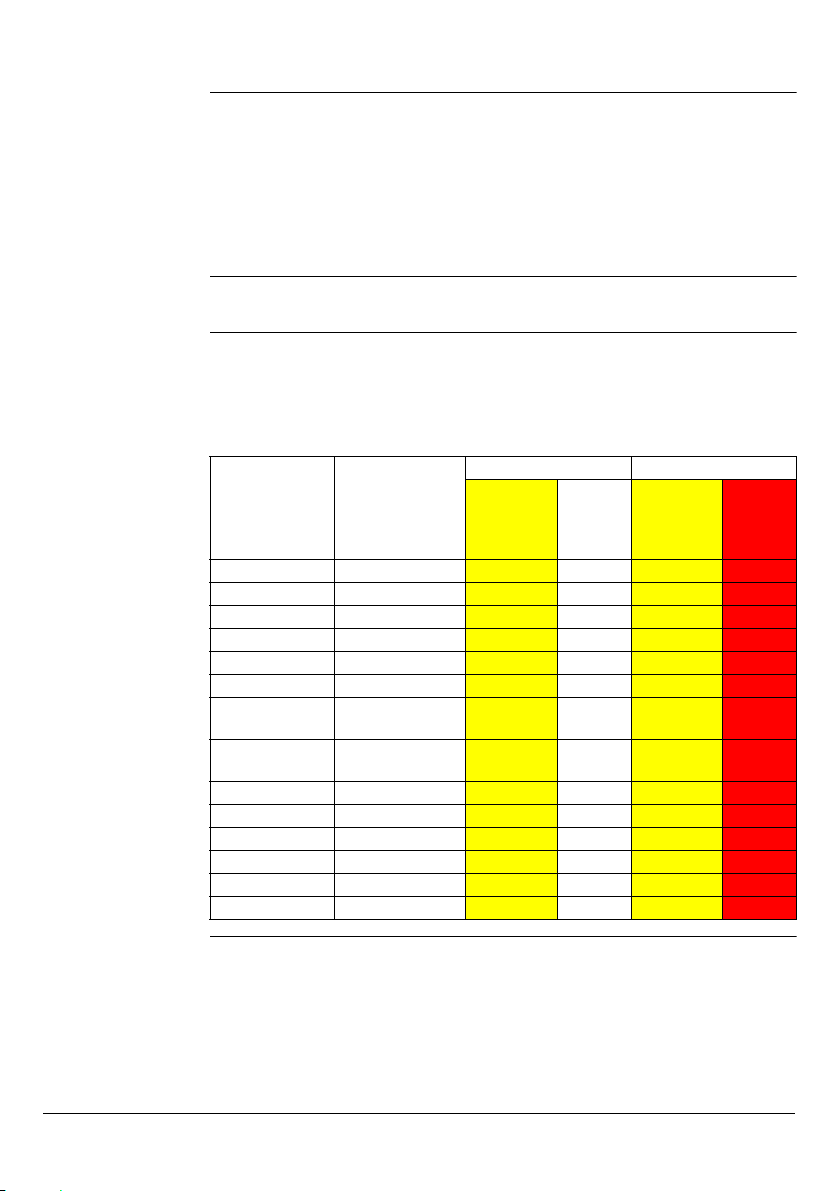
When the mojoXact Plus/third-party terminal system is turned on for the first time,
the Universal Terminal Unlock screen, shown below, appears.
Page 21
Loading the unlock
code manually,
step-by-step
To unlock the universal terminal features of the system, carry out the following steps:
1. Select the Unlock Code field and enter the unlock code taking care with capital
letters and numbers, as the code is case sensitive.
2. Select the button.
If the unlock code was entered correctly and is accepted by the system, the Initial
Setup Wizard starts and its screen appears (refer to Section "3.3 Initial Setup
Wizard").
If an error occurred and the code was not accepted by the system, the message
"Invalid Authentication Code" displays below the Unlock Code field. Re-enter the
unlock code taking care with capitalization and numbers.
Loading the unlock
code from a USB
memory key, stepby-step
Leica mojoXact Plus, Running the mojoXact Plus for the First Time 21
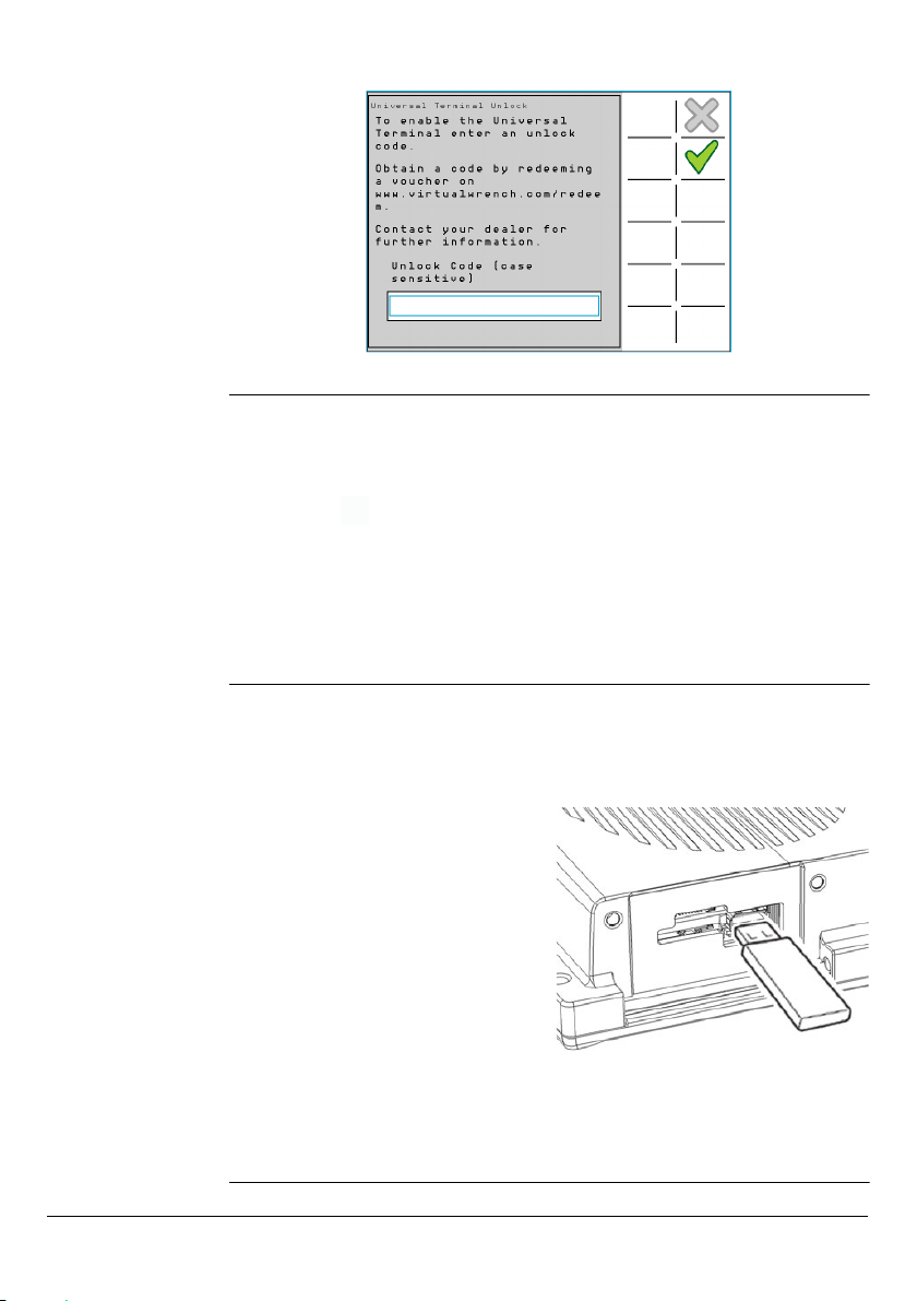
If you received a USB memory key from your dealer with the unlock code on it, carry
out the following steps to load the unlock code onto your mojoXact Plus:
The mojoXact Plus must be powered down.
1. The USB interface is at the front of the
mojoXact Plus. Unscrew the door at
the front so it can open and lie flat, and
insert the USB memory key that has
the unlock code loaded onto it, into
the USB slot.
2. Power up the mojoXact Plus, by turning on the vehicle’s ignition.
When the mojoXact Plus powers up, it automatically detects the USB memory key
and loads the universal terminal unlock code. When this process is complete, the
Initial Setup Wizard starts and the its screen appears (refer to Section "3.3 Initial
Setup Wizard").
Page 22
3.3 Initial Setup Wizard
Overview The initial setup wizard executes once the universal terminal features of the
mojoXact Plus system have been unlocked and its initial screen appears.
The setup wizard steps the operator through the initial setup process allowing the
operator to setup:
• Region settings such as the region (or country), and units to use for length,
speed and area.
• Vehicle type and setup.
• Terrain compensation.
• The physical orientation of the mojoXact Plus.
The setup wizard can be executed at any time should there be the need to change
the initial settings. Section "3.5 Running the Setup Wizard at any Time" provides
instructions on how to access the setup wizard at any time.
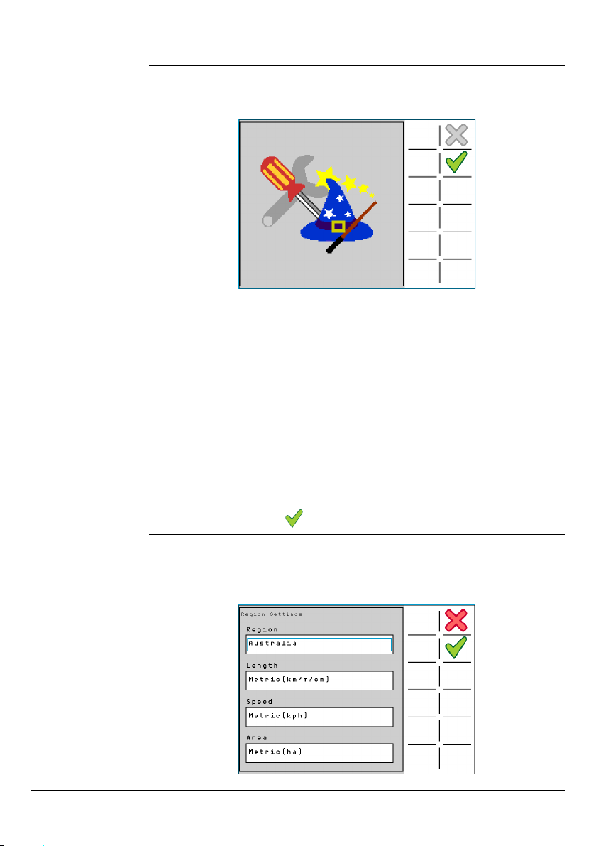
1. To proceed to the first configuration screen of the Initial Setup Wizard, the
Region Settings, select .
Region settings,
step-by-step
22 Running the mojoXact Plus for the First Time, Leica mojoXact Plus
The Region Settings screen is the first configuration screen of the setup wizard. It
allows the operator to set the region (or country), and units to use for length, speed
and area.
Page 23
1. On the Region Settings screen, select the region (or country) from the Region
list.
2. Select the units to use for length from the Length list. Lengths may be measured
in Metric, Imperial, or US Standard units.
3. Select the units to use for speed from the Speed list. Speeds may be measured
in Metric, Imperial, or US Standard units.
4. Select the units to use for area from the Area list. Areas may be measured in
Metric, Imperial, or US Standard units. The Imperial acre is the defined international acre, and the US acre is the slightly smaller US Survey acre.
5. To accept the Region settings and proceed through the setup wizard to the
Vehicle Type screen, select .
Vehicle setup,
step-by-step
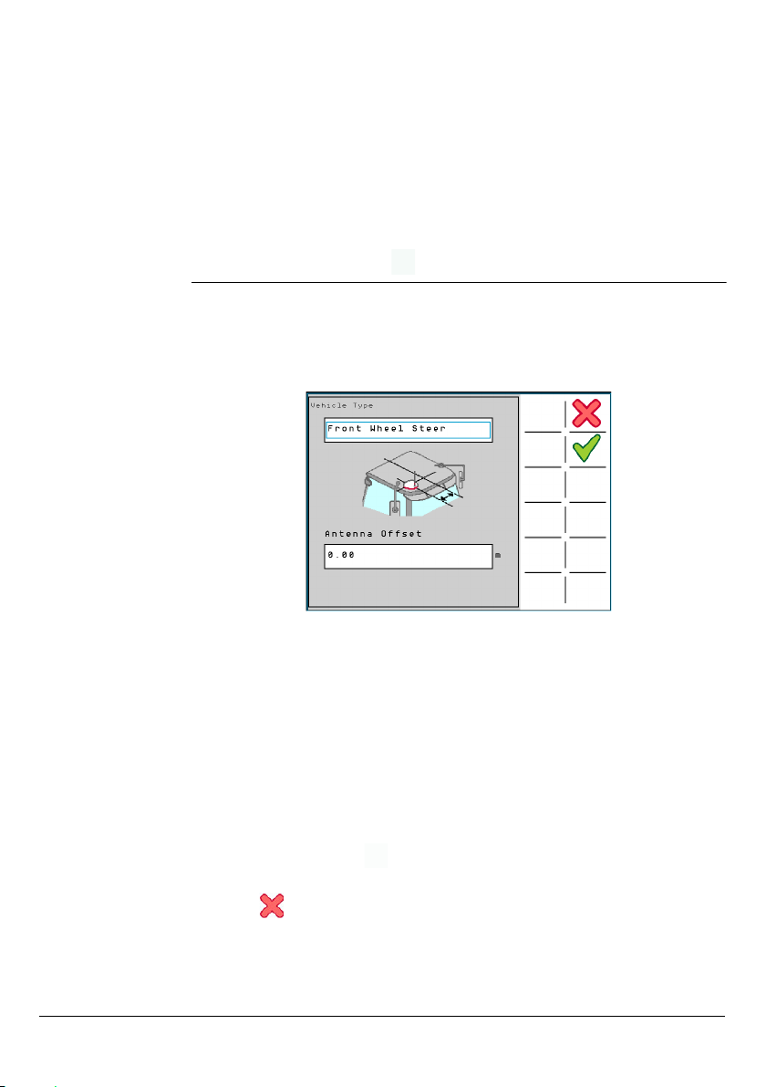
To setup the vehicle, carry out the following steps:
1. On the Vehicle Type screen (shown below), select your Vehicle Type from the
list.
2. In the Antenna Offset field, enter the value in the units appropriate for the
configured region, for how far the antenna is mounted from the center of the
wheel tracks, or vehicle’s cab (providing the cab is centered over the wheel
tracks), as indicated by the graphic. Ideally this value should be zero as the
antenna should be mounted in the center of the vehicle’s cab towards the front.
If the antenna is mounted to the right of the center of the vehicle (when facing
the forward direction of travel), enter the Antenna Offset as a positive value. If
the antenna is mounted to the left of the center of the vehicle, enter the
Antenna Offset as a negative value.
3. To accept the values and proceed through the setup wizard to the Vehicle
Settings screen, select .
To cancel any change to the value and return to the Region Settings screen,
select .
Leica mojoXact Plus, Running the mojoXact Plus for the First Time 23
Page 24

4. Enter the measurements required for the vehicle type that you have selected.
5. To accept the values and proceed through the setup wizard to the Terrain
Compensation screen, select .
To cancel any changes to the values and return to the Vehicle Type screen, select
.
Terrain compensation, step-by-step
As this is the first time that a terrain compensation is to be performed, the Terrain
Compensation screen appears with New Compensation selected by default. To
perform terrain compensation you must have the vehicle in a suitable location that
has a flat area large enough to be able to turn the vehicle around.
If it is not convenient to perform the terrain compensation at this time, the New
Compensation field can be de-selected. However, the system does not permit the
vehicle to be auto-steered until a terrain compensation has been performed, and you
will see the terrain compensation error appear until this has occurred. To perform
terrain compensation later, refer to Section "4.2 Terrain Compensation".
For accurate positioning and guidance, it is important to perform terrain compensation as this feature allows the mojoXact Plus to calculate the position of the GPS
antenna as the vehicle navigates unlevel terrain. This is demonstrated by the picture
below which illustrates a vehicle tilting as it would on hilly terrain. Without terrain
compensation, the position of the vehicle is shown by the uncorrected position. With
24 Running the mojoXact Plus for the First Time, Leica mojoXact Plus
Page 25
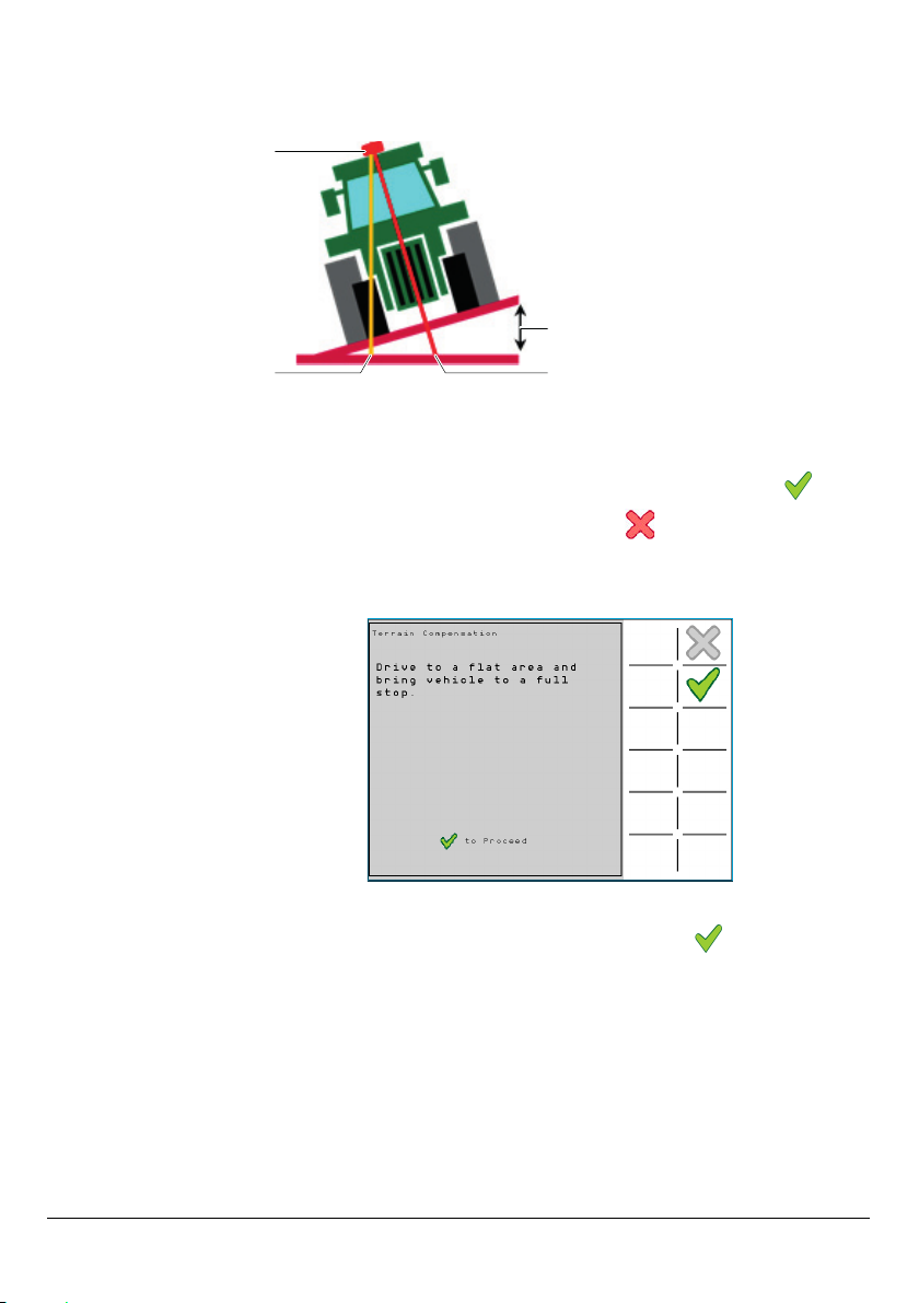
terrain compensation, the position of the vehicle is the corrected position. The differ-
a
b
c
d
ence in these two positions is obvious, clearly demonstrating why the use of terrain
compensation is necessary for accurate positioning and guidance.
a) GPS antenna
b) Uncorrected position
c) Roll angle
d) Corrected position
To setup terrain compensation, carry out the following steps:
1. Ensure that the New Compensation checkbox is checked, and select .
To return to the Vehicle Settings screen, select .
2. Follow the directions on the screen and drive to a flat area and bring the vehicle
to a full stop.
3. To proceed with the Terrain Compensation setup, select . The operator is
instructed not to move the vehicle as tuning of the sensors is in progress.
Leica mojoXact Plus, Running the mojoXact Plus for the First Time 25
Page 26
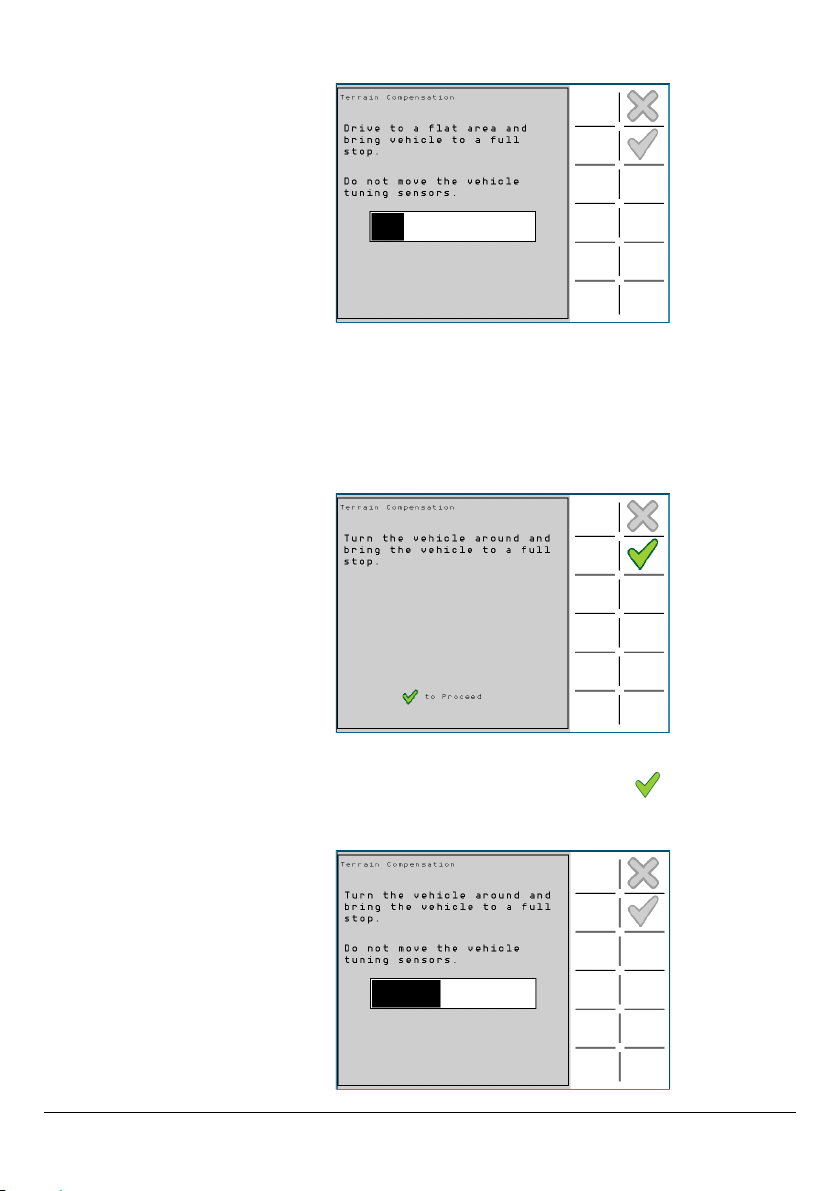
4. Follow the directions on the screen and turn the vehicle around through 180o and
bring the vehicle to a full stop in the same position as before. To do this, take
note of where the vehicle’s right front tyre is parked. Turn the vehicle around
through 180o and stop in exactly the same position prior to the turn, so the
vehicle’s left rear tyre is parked where the right front tyre was previously parked.
5. To proceed with the Terrain Compensation setup, select . The operator is
instructed not to move the vehicle as tuning of the sensors is in progress.
26 Running the mojoXact Plus for the First Time, Leica mojoXact Plus
Page 27
6. When tuning is complete, select to proceed to the mojoXact Plus Orientation
screen.
To return to the initial Terrain Compensation screen, select .
mojoXact Plus
orientation, overview
When the mojoXact Plus Orientation screen appears, the image shows how the
mojoXact Plus is mounted in the vehicle, as far as it being mounted flat or on one of
its sides. This is determined during the Terrain Compensation process.
If the Terrain Compensation process during the Initial Setup Wizard is skipped, the
mounting of the mojoXact Plus will not be correctly determined, and it will be necessary to return to the mojoXact Plus Orientation once the Terrain Compensation has
been performed. To setup the mojoXact Plus Orientation at a later time, refer to
Section "4.2 Terrain Compensation".
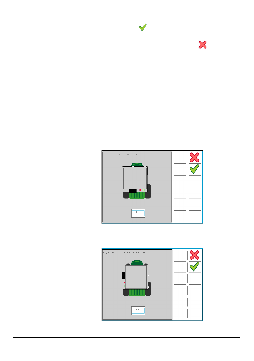
The orientation value is the degrees that the front of the mojoXact Plus is mounted
to the front of the vehicle. The front of the mojoXact Plus is where the USB port and
SIM card slot are accessed (and therefore the back is where all of the cables are
attached). For example, a mojoXact Plus mounted flat at 0 degrees to the front of
the vehicle, looks like this:
A mojoXact Plus mounted flat at 90 degrees to the front of the vehicle, looks like this:
Leica mojoXact Plus, Running the mojoXact Plus for the First Time 27
Page 28
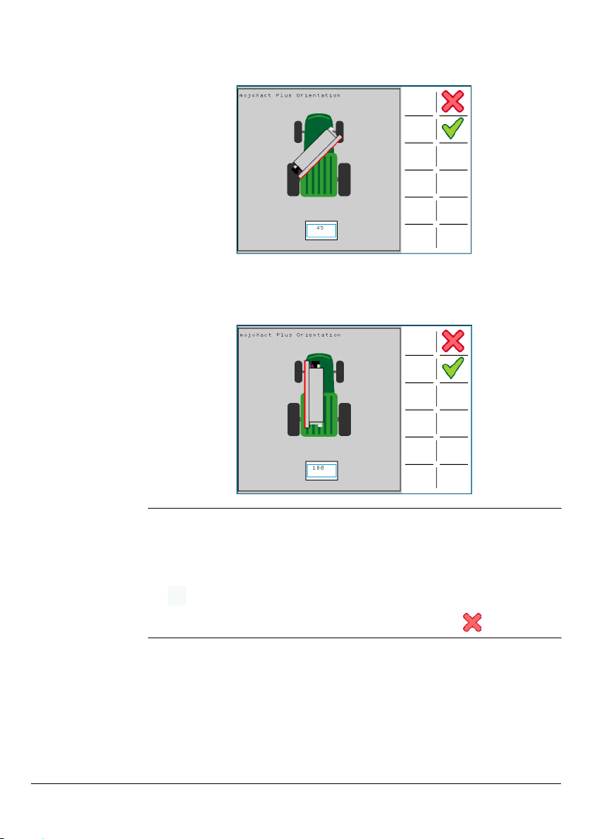
A mojoXact Plus mounted on its side at 45 degrees to the front of the vehicle, looks
like this:
A mojoXact Plus mounted on its side at 180 degrees to the front of the vehicle, looks
like this:
mojoXact Plus
orientation setup,
step-by-step
28 Running the mojoXact Plus for the First Time, Leica mojoXact Plus
To setup the orientation of the mojoXact Plus, carry out the following steps:
1. At the mojoXact Plus Orientation screen, enter the orientation of the
mojoXact Plus.
2. To complete the Initial Setup Wizard and go to the main navigation screen, select
.
To return to the initial Terrain Compensation screen, select .
Page 29
3.4 Main Navigation Screen
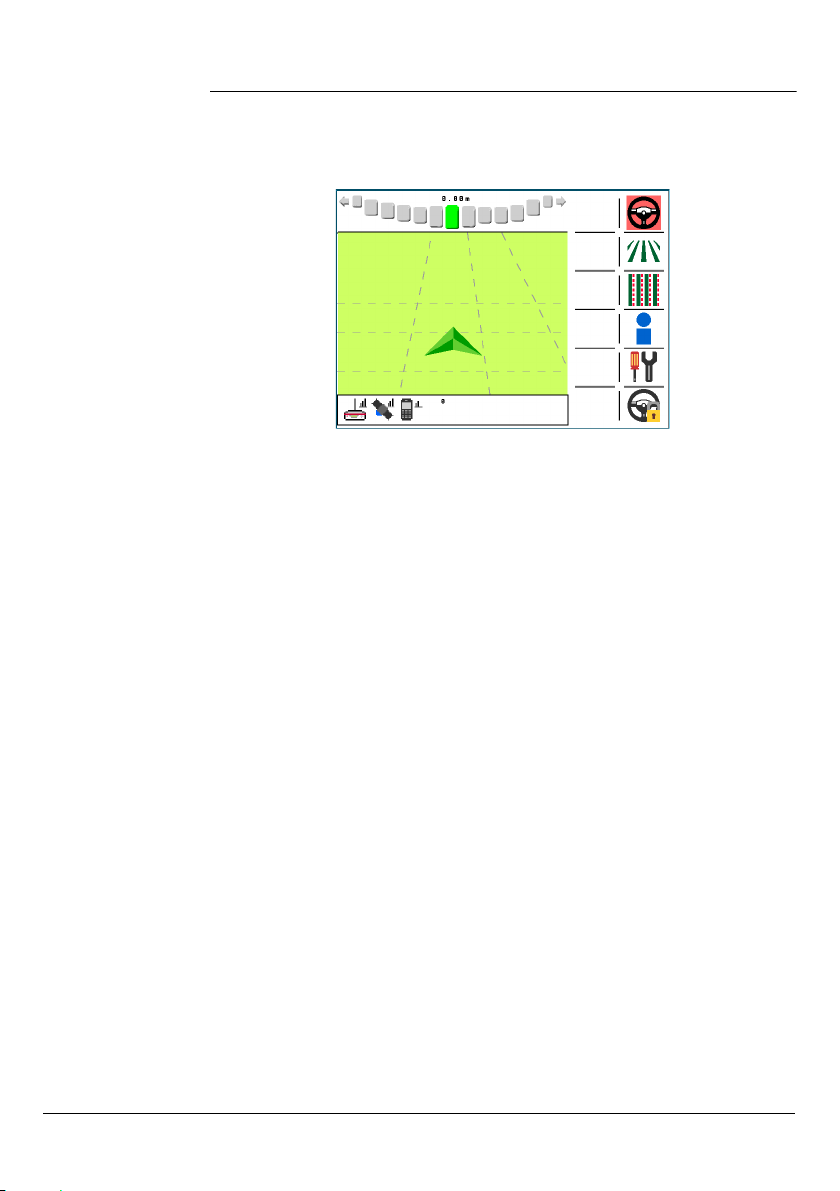
Once the Initial Setup Wizard is complete the main navigation screen is displayed. The
main navigation screen is the screen that the operator will view most of the time
during normal operation.
The main navigation screen has four main parts: the lightbar, main display, information area and menu bar.
1. Lightbar
The lightbar is located at the top of the screen. It is a Leica Geosystems Smart
lightbar which uses both crosstrack error and heading error to guide the operator
to the line.
2. Main Display
The main part of the screen shows AB lines in perspective and highlights the line
that is engaged (or cannot be engaged). Horizontal dotted lines are used to show
movement when on the lines. Brief descriptions of current errors appear at the
bottom of this part of the screen.
3. Information Area
The information area is located at the bottom of the screen. Centered at the top
of this area is the row number that is currently engaged or that can be engaged.
Below this are icons that represent the current connection statuses of:
• The Correction Source in use (Network RTK, Internal Radio, External Radio or
GL1DETM). Refer to Chapter "6 Correction Sources" for details on setting up a
correction source and diagnosing connection errors.
• The GPS connection.
• The cell modem signal. Refer to Section "3.6.2 Cell Modem Settings" for details
on setting up the cell modem and diagnosing connection errors.
• Virtual Wrench. Refer to Chapter "10 Virtual Wrench Remote Service" for
details on connecting to Virtual Wrench and diagnosing connection errors.
4. Menu Bar
The menu bar is located on the right side of the screen and provides buttons for:
Leica mojoXact Plus, Running the mojoXact Plus for the First Time 29
Page 30
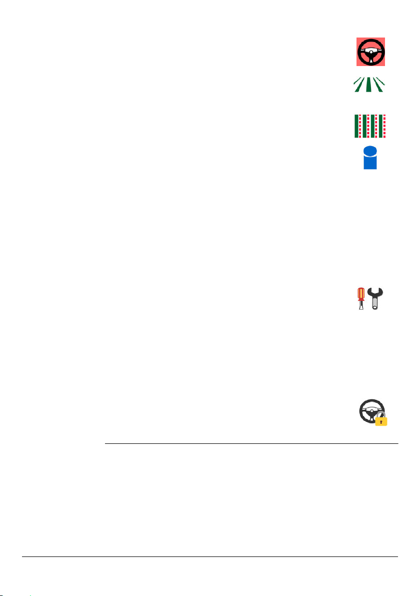
Auto-Steer
Engage
Guidance • Setting AB, A+ Heading and Pivot waylines.
Nudge • Nudge options to correct GPS drift.
Service &
Information
Settings • System Settings - refer to Sections "3.6 Changing
Roading
Lock/Unlock
• Auto-Steer engage and disengage.
Refer to Chapter "5 Auto-Steer" for details on the
auto-steer feature and how to use it.
• Wayline management.
Refer to Chapter "7 Guidance" for details on
setting up waylines and wayline management.
Refer to Section "7.6 Nudge" for details on using
the nudge feature.
• System Status Information - refer to Section "9.1
Status Information" for details.
• Errors - refer to Section "9.6 Error Notifications"
for details.
• Position Information - refer to Section "9.2 Position Information" for details.
• Correction Source Information - refer to Section
"6.5 Correction Source Status" for details
• Device Information - refer to Section "9.4 Device
Information" for details.
• Cell Modem Information - refer to Section "9.5 Cell
Modem Status" for details.
• Connection to Virtual Wrench - refer to Chapter
"10 Virtual Wrench Remote Service" for details.
System Settings", "3.5 Running the Setup Wizard
at any Time" and "3.7 Feature Unlock" for details.
• Vehicle Settings - refer to Chapter "4 Vehicles and
Implements" for details.
• Steering Settings - refer to Chapter "5 Auto-Steer"
for details.
• Correction Settings - refer to Chapter "6 Correction
Sources" for details.
• Software Settings - refer to Chapter "11 Software
Maintenance" for details.
• Roading engage and disengage.
Refer to Section "5.1 Engage Auto-Steer" for
details on how to turn the roading safety feature
on and off.
30 Running the mojoXact Plus for the First Time, Leica mojoXact Plus
Page 31

3.5 Running the Setup Wizard at any Time
General information
Running the setup
wizard, step-bystep
The Setup Wizard can be run at any time after the initial setup of the mojoXact Plus.
The wizard guides the operator through the majority of the system setup, that is:
Region Setup, Vehicle Setup, Terrain Compensation and mojoXact Plus Orientation.
Alternatively the operator is able to setup specific features through the Settings
menu and System Settings menu. These features include:
• Vehicle Settings (refer to Chapter "4 Vehicles and Implements")
• Steering Settings (refer to Chapter "5 Auto-Steer")
• Correction Source Settings (refer to Chapter "6 Correction Sources")
• Software Settings (refer to Chapter "11 Software Maintenance")
• Region Settings (refer to Section "3.6.1 Changing Region Settings")
• Cell Modem Settings (refer to Section "3.6.2 Cell Modem Settings")
• NMEA Settings (refer to Chapter "8 NMEA Output")
To run the Setup Wizard, carry out the following steps:
1. On the main navigation screen, select the Settings button.
The Settings menu appears.
2. On the Settings menu, select the System Settings button.
The System Settings menu appears.
3. On the System Settings menu, select the Setup Wizard button.
The Setup Wizard runs and the Region Settings screen appears.
4. Proceed through the Setup Wizard - refer to Section "3.3 Initial
Setup Wizard" for details, making any changes that are required.
You are returned to the main navigation screen at the completion
of the setup wizard.
3.6 Changing System Settings
General information
Changing settings,
step-by-step
Leica mojoXact Plus, Running the mojoXact Plus for the First Time 31
The system settings include:
• Country settings
• Measurement units (length, speed and area)
• Cell modem settings
To select and change one of these settings, carry out the following steps:
1. On the main navigation screen, select the Settings button.
The Settings menu appears.
2. On the Settings menu, select the System Settings button.
The System Settings menu appears, providing access to the
system settings, some of which are detailed below.
Page 32

3.6.1 Changing Region Settings
Region settings include the Country settings, and the units of measure to use for
length, speed and area. To change the region settings carry out the following steps:
1. On the System Settings menu, select the Region Settings button.
The Region Settings screen appears.
2. To change the region or country, select the new one from the Region list.
3. To change the units to use for length, select the new one from the Length list.
Lengths may be measured in Metric, Imperial, or US Standard units.
4. To change the units to use for speed, select the new one from the Speed list.
Speeds may be measured in Metric, Imperial, or US Standard units.
5. To change the units to use for area, select the new one from the Area list. Areas
may be measured in Metric, Imperial, or US Standard units. The Imperial acre is
the defined international acre, and the US acre is the slightly smaller US Survey
acre.
6. To accept the Region settings and return to the main navigation screen, select
.
To cancel any changes to the values and return to the System Settings menu,
select .
3.6.2 Cell Modem Settings
The mojoXact Plus allows the operator to choose an internal modem, external
ethernet modem or no modem. To setup the cell modem carry out the following
steps:
1. On the System Settings menu, select the Cell Modem Settings
button.
The Modem Settings screen appears.
32 Running the mojoXact Plus for the First Time, Leica mojoXact Plus
Page 33

If the mojoXact Plus’ internal modem is used (and it will be in HSPA regions), a
Network Data plan for the mojoXact Plus and a SIM card with an active data plan are
required before you can utilize the online features of the mojoXact Plus. Contact your
dealer to obtain the required unlock vouchers.
If the internal cell modem is selected, the operator may be required to enter further
information. This information is available from your cellular network provider.
2. At the Modem Settings screen, select Internal to use the mojoXact Plus’ internal
cell modem, External if the mojoXact Plus is connected to an external ethernet
modem or None if you do not want to setup the cell modem at this time.
3. To accept the selection and move to the second screen for Cell Modem setup (if
an internal cell modem is selected), select .
To cancel any change to the value and return to the System Settings menu, select
.
The second Modem Settings screen allows the operator to configure the APN, and
enter their user name and password. This screen only appears if an internal modem
is being setup.
4. At the second Modem Settings screen, check that the value in the APN field is
correct. If it is not, enter the correct value.
5. Enter the supplied user name in the Username field.
Leica mojoXact Plus, Running the mojoXact Plus for the First Time 33
Page 34

6. Enter the supplied password in the Password field.
7. To accept the values and move to the third screen for Cell Modem setup, select
.
To cancel any changes to the values and return to the previous Modem Settings
screen, select .
The third Modem Settings screen allows the operator to configure the Cell Network
Mode and SIM Card PIN.
8. The cell network mode defaults to Automatic. If this is not the correct setting for
your situation, select the correct value from the Cell Network Mode list.
9. If you have been assigned a personal identification number (PIN) for the
subscriber identity module (SIM) of the cell modem, enable the Use SIM Card PIN
checkbox.
10. Enter the PIN in the SIM Card PIN field.
11. To accept the values and return to the main navigation screen, select .
34 Running the mojoXact Plus for the First Time, Leica mojoXact Plus
If you make an error when entering the SIM PIN, it will be necessary to
remove the SIM card and reset it by entering a Personal Unblocking Code
(PUK), which you can obtain from your network provider.
To cancel any changes to the values and return to the second Modem Settings
screen, select .
The Cell Modem icon displays in the information area at the bottom of the main
navigation screen. indicates a successful connection with good signal
strength, indicates that the connection is successful but the signal strength
is poor and indicates that the connection was not successful.
Page 35

Troubleshooting
connection problems
If the signal strength is poor, but you have a good signal on your mobile phone,
check:
• that the cell antenna is not obstructed or damaged, and that its cable is not
damaged.
• that the Cell Network Mode field at the third Modem Settings screen is appropriately set for your region.
If the cell modem connection was not successful, check:
• that the values entered in the APN, Username and Password fields are correct.
• that you have an active data plan for the SIM Card.
• that the cell antenna and its cable are not damaged.
• that the Cell Network Mode field at the third Modem Settings screen, is appropriately set for your region.
3.7 Feature Unlock
Some features are not enabled by default on the mojoXact Plus, and these include:
• John Deere R Series
• Network Upgrade
• Network Data Plan
•Virtual Vista
•Universal Terminal
To access these features it is necessary to purchase a voucher from your dealer
which will give you a code that is used to unlock the feature. Features can be
unlocked using the steps below or Virtual WrenchTM as explained in Chapter "10
Virtual Wrench Remote Service".
Unlocking a
feature, step-bystep
Leica mojoXact Plus, Running the mojoXact Plus for the First Time 35
To unlock a feature, carry out the following steps:
1. On the main navigation screen, select the Settings button.
The Settings menu appears.
2. On the Settings menu, select the System Settings button.
The System Settings menu appears.
3. On the System Settings menu, select the Feature Settings
button.
The Features screen (shown below) appears, with a list of features
and their availability, that is, whether they are locked or unlocked.
Page 36

4. To activate a new feature, select the Enter New Code button.
A second Features screen displays with the Enter Code field.
5. Enter the new code taking care with capitalization and numbers,
as the code is case sensitive.
6. To save the code and return to the initial Features screen, select .
The list of features updates to show that the feature was successfully unlocked.
To discard the code and return to the initial Features screen, select .
7. To return to the main navigation screen, select .
To return to the System Settings menu, select .
36 Running the mojoXact Plus for the First Time, Leica mojoXact Plus
Page 37

Leica mojoXact Plus, Running the mojoXact Plus for the First Time 37
Page 38

4 Vehicles and Implements
General information
If the vehicle setup was not completed correctly during the initial setup using the
Initial Setup Wizard, or the mojoXact Plus has been re-positioned in the vehicle or
moved to a different vehicle, it maybe necessary to adjust the vehicle and implement
settings, including:
• Vehicle type selection and measurements.
• Terrain compensation and mojoXact Plus orientation.
• Implement measurements.
How to setup vehicles and implements when the mojoXact Plus is used with a thirdparty terminal is described in this chapter.
For information on how to set up vehicles and implements when the mojoXact Plus
is used with a Leica mojo3D, refer to the Leica mojo3D User Manual.
4.1 Vehicle Measurement Setup
Overview Vehicle measurement setup involves selecting the type of vehicle that the
Vehicle measurement setup, stepby-step
mojoXact Plus is installed in and entering measurements for the:
• Antenna Offset - how far the antenna is mounted from the center of the
vehicle’s wheel tracks.
• Antenna Height - how far the antenna is mounted above ground-level.
• Antenna to Fixed Axle - how far the antenna is mounted from the vehicle’s fixed
axle.
To select the vehicle type and configure its measurements, carry out the following
steps:
1. On the main navigation screen, select the Settings button.
The Settings menu appears.
2. On the Settings menu, select the Vehicle Settings button.
The Vehicle Settings menu appears.
38 Vehicles and Implements, Leica mojoXact Plus
Page 39

3. On the Vehicle Settings menu, select the Vehicle Measurements
button.
The Vehicle Type screen, shown below, appears.
4. On the Vehicle Type screen, select your vehicle type from the list.
5. In the Antenna Offset field, enter the value in the units appropriate for the
configured region, for how far the antenna is mounted from the center of the
wheel tracks, or vehicle’s cab (providing the cab is centered over the wheel
tracks), as indicated by the graphic. Ideally this value should be zero as the
antenna should be mounted in the center of the vehicle’s cab towards the front.
If the antenna is mounted to the right of the center of the vehicle (when facing
the forward direction of travel), enter the Antenna Offset as a positive value. If
the antenna is mounted to the left of the center of the vehicle, enter the
Antenna Offset as a negative value.
6. To accept the values and proceed to the Vehicle Settings screen, select .
To cancel any changes to the values and return to the Vehicle Settings menu,
select .
7. At the Vehicle Settings screen, an example of which is shown below, enter the
measurements required for the vehicle type that you have selected.
Leica mojoXact Plus, Vehicles and Implements 39
Page 40

8. To accept the values and return to the main navigation screen, select .
a
b
c
d
To cancel any changes to the values and return to the Vehicle Type screen, select
.
4.2 Terrain Compensation
Explanation For accurate positioning and guidance, it is important to perform terrain compensa-
Terrain compensation setup, stepby-step
tion as this feature allows the mojoXact Plus to calculate the position of the GPS
antenna as the vehicle navigates unlevel terrain. This is demonstrated by the picture
below which illustrates a vehicle tilting as it would on hilly terrain. Without terrain
compensation, the position of the vehicle is shown by the uncorrected position. With
terrain compensation, the position of the vehicle is the corrected position. The difference in these two positions is obvious, clearly demonstrating why the use of terrain
compensation is necessary for accurate positioning and guidance.
a) GPS antenna
b) Uncorrected position
c) Roll angle
d) Corrected position
To perform terrain compensation, carry out the following steps:
1. On the main navigation screen, select the Settings button.
The Settings menu appears.
2. On the Settings menu, select the Vehicle Settings button.
The Vehicle Settings menu appears.
40 Vehicles and Implements, Leica mojoXact Plus
Page 41

3. On the Vehicle Settings menu, select the Terrain Compensation
button.
The Terrain Compensation screen, shown below, appears.
If a terrain compensation has never been performed, only the New Terrain
Compensation option is available. If a terrain compensation has been performed
previously, the operator has the choice of performing a new terrain compensation or an update to the existing terrain compensation or no terrain compensation at all.
New Terrain Compensation - clears all previous compensation data. This option
should be used when the mojoXact Plus has been re-installed or moved.
Update Terrain Compensation - improves compensation performance. This
option should only be used when the mojoXact Plus has not been re-installed or
moved in the vehicle.
4. At the Terrain Compensation screen, select the option that is suitable for your
equipment and circumstances, or if you do not wish to perform a terrain compensation, do not select an option.
5. To proceed with terrain compensation, select .
To return to the Vehicle Settings menu and not perform the terrain compensa-
tion, select .
Leica mojoXact Plus, Vehicles and Implements 41
Page 42

6. Follow the directions on the screen and drive to a flat area and bring the vehicle
to a full stop.
7. To proceed with terrain compensation, select . The operator is instructed not
to move the vehicle as tuning of the sensors is in progress.
42 Vehicles and Implements, Leica mojoXact Plus
Page 43

8. Follow the directions on the screen and turn the vehicle around through 180o and
bring the vehicle to a full stop in the same position as before. To do this, take
note of where the vehicle’s right front tyre is parked. Turn the vehicle around
through 180o and stop in exactly the same position prior to the turn, so the
vehicle’s left rear tyre is parked where the right front tyre was previously parked.
9. To proceed with terrain compensation, select . The operator is instructed not
to move the vehicle as tuning of the sensors is in progress.
Leica mojoXact Plus, Vehicles and Implements 43
Page 44

10. When tuning is complete, select to proceed to the mojoXact Plus Orientation
screen, shown below.
To return to the initial Terrain Compensation screen, select .
When the mojoXact Plus Orientation screen appears, the image shows how the
mojoXact Plus is mounted in the vehicle, as far as it being mounted flat or on one of
its sides. This is determined during the Terrain Compensation process.
The orientation value is the degrees that the front of the mojoXact Plus is mounted
to the front of the vehicle. The front of the mojoXact Plus is where the USB port and
SIM card slot are accessed (and therefore the back is where all of the cables are
attached). For example, a mojoXact Plus mounted flat at 0 degrees to the front of
the vehicle, looks like this:
44 Vehicles and Implements, Leica mojoXact Plus
Page 45

A mojoXact Plus mounted flat at 90 degrees to the front of the vehicle, looks like this:
A mojoXact Plus mounted on its side at 45 degrees to the front of the vehicle, looks
like this:
A mojoXact Plus mounted on its side at 180 degrees to the front of the vehicle, looks
like this:
11. At the mojoXact Plus Orientation screen, enter the orientation of the
mojoXact Plus.
Leica mojoXact Plus, Vehicles and Implements 45
Page 46

12. To complete terrain compensation and return to the main navigation screen,
select .
To return to the Vehicle Settings menu, select .
4.3 Implement Setup
Overview Implement setup allows the operator to configure measurements for an implement
Implement setup,
step-by-step
that may be attached to the vehicle. These measurements are typically the width of
the implement and its offset from the center of the vehicle’s wheel tracks.
To configure implement measurements, carry out the following steps:
1. On the main navigation screen, select the Settings button.
The Settings menu appears.
2. On the Settings menu, select the Vehicle Settings button.
The Vehicle Settings menu appears.
3. On the Vehicle Settings menu, select the Implement Settings
button.
The Implement Settings screen appears.
4. In the Implement Width field, enter the entire width of the implement (as shown
in the graphic).
5. If the implement is offset to one side of the vehicle, that is, it is not centered
behind the vehicle, select the Implement Offset checkbox.
The Implement Offset field appears.
46 Vehicles and Implements, Leica mojoXact Plus
Page 47

As illustrated by the graphic, the implement offset is the distance between the
2.50 m
2.50 m
8.00 m8.00 m
center of the vehicle and the center of the implement. If the implement is offset
to the right of the center of the vehicle (when facing the forward direction of
travel), enter the Implement Offset as a positive value. If the implement is offset
to the left of the center of the vehicle, enter the Implement Offset as a negative
value.
Implement offset to the right implement offset to the left
6. To accept the values and return to the main navigation screen, select .
To cancel any changes to the values and return to the Vehicle Settings menu,
select .
Leica mojoXact Plus, Vehicles and Implements 47
Page 48

5 Auto-Steer
Overview Auto-steer is the main feature offered by the mojoXact Plus. This chapter discusses
the following for systems that have a mojoXact Plus that is used with a third-party
terminal:
• the auto-steer states and the buttons that reflect these.
• the roading safety feature and how to turn it on and off.
• how to engage and disengage auto-steer.
• how to select, setup and calibrate a steer kit.
• the stationary engage and reverse steering features.
• tuning auto-steer performance.
• testing auto-steer.
For information on the auto-steer feature when the mojoXact Plus is used with a
Leica mojo3D, refer to the Leica mojo3D User Manual.
5.1 Engage Auto-Steer
Auto-steer status The auto-steer button on the main navigation screen is used to engage and disen-
gage auto-steer. The colour of this button also indicates the current status of the
auto-steer.
• Red: Roading is active and auto-steer can not be engaged until
roading is turned off.
• Orange: Roading is turned off, but the conditions for auto-steer to
engage have not been met and auto-steer can not be engaged.
Stationary engage is not armed.
• Yellow: Roading is turned off and auto-steer is ready, but not
currently engaged. If the steering button is tapped the system will
auto-steer immediately because all engage criteria are currently
satisfied.
• Green with Pause: Auto-steer is armed but not active because the
vehicle is not moving or the engage criteria are not satisfied.
• Green: Auto-steer is engaged and the vehicle is being automatically steered.
5.1.1 Roading Safety Feature
The Roading feature is a safety tool that is designed to prevent accidental engagement of automatic steering when it should not be engaged: for example, when a
vehicle is on a public road, or when working around obstacles. Roading is active when
the auto-steer button is red, .
48 Auto-Steer, Leica mojoXact Plus
Page 49

Turn Roading On To enable roading, carry out the following steps:
1. On the main navigation screen, select the roading button.
Roading is enabled and the Roading button changes to have a
locked padlock, . The auto-steer button turns red.
Disabling Roading Roading can only be disabled if the steer kit is configured correctly and is actively
Turn Roading Off To disable roading, carry out the following steps:
communicating.
1. When the auto-steer button is red, select the roading button.
Roading is disabled and the roading button changes to have an
unlocked padlock . The auto-steer button changes to the
color that reflects its current state.
5.1.2 Preconditions to Engage Auto-steer
The conditions required for auto-steer to engage depend on the steer kit being used.
The following is a typical example of the conditions required to be met before automatic steering can occur:
• Steer kit correctly connected and configured
• Roading turned off
• Wayline set
• Distance to wayline less than 6 m (20 ft)
• Heading within 45 degrees of wayline
• Travelling faster than 1 km/h (0.6 mph)
• Not travelling faster than 30 km/h (18 mph)
5.1.3 Engage Auto-steer
Providing the preconditions for the steer kit have been met, auto-steer can be
engaged by carrying out the steps below:
1. On the main navigation screen, select the auto-steer button when
it is yellow.
2. The auto-steer button turns green to indicate auto-steer is engaged and the
vehicle is being automatically steered.
Leica mojoXact Plus, Auto-Steer 49
Other methods to engage the steering will be available and these methods
will depend on the steer kit used.
Page 50

5.1.4 Disengage Auto-steer
To disengage auto-steer, carry out the steps of one of the following methods:
1. On the main navigation screen, select the auto-steer button when
it is green.
The auto-steer button turns yellow or orange to indicate auto-steer
is disengaged and the vehicle is no longer being automatically
steered.
OR
1. On the main navigation screen, select the roading button.
The auto-steer button turns red indicating that roading is turned
on, the roading button changes to have a locked padlock , and
auto-steer is disengaged.
Other methods to disengage the steering will be available and these
methods will depend on the steer kit used.
5.2 Steer Kit Selection and Setup
General Introduction
Selecting and
setting up a steer
kit, step-by-step
This section describes how to select and setup a steer kit, and troubleshoot problems, should they occur.
To select a Steer Kit and set it up, carry out the following steps:
1. On the main navigation screen, select the Settings button.
The Settings menu appears.
2. Select the Steering Settings button.
The Steering Settings menu appears.
50 Auto-Steer, Leica mojoXact Plus
Page 51

3. Select the Steer Kit Setup button.
The Setup Steer Kit screen appears.
4. Select the appropriate steer kit from the list.
5. To accept the selection and continue with the setup process, select the
button. What screen appears next is dependent on the steer kit that is selected.
To cancel the selection and go back to the Steering Settings menu, select the
button.
6. If the Manufacturer screen appears (followed by the Model screen), make the
appropriate selection from the Manufacturer list and then from the Model list.
7. To accept the selections and continue with the setup process, select the
button. The Steering Kit Status screen appears.
To go back to the Steering Settings menu, select the button.
8. Both of the CAN Bus Connected and Steering Kit Active indicators on the Steering
Kit Status screen should have a icon to their left. If they do not it is necessary to diagnose and correct the problems, otherwise it will not be possible to
engage auto-steer. Refer to Section "5.2.1 Troubleshooting Steer Kit and CAN
Bus Problems" for suggestions.
Leica mojoXact Plus, Auto-Steer 51
Page 52

9. To proceed with the steer kit setup, select the button. What screen appears
next is dependent on the steer kit that is selected.
To go back to the previous screen, select the button.
If the Steer Configuration screen appears, the operator has the opportunity to
write the configuration to the steering controller. Caution must be exercised
before writing the configuration to the steering controller, to ensure that the
steering controller does not contain any configuration that is needed, as the send
configuration operation will overwrite any existing configuration in the steering
controller with factory defau lt settings.
10. If the Steer Configuration screen appears, and you are certain that the steering
controller needs to have configuration written to it, select Configure in the list.
If you are unsure about writing configuration to the steering controller, or you
know that the steering controller is configured, select Skip in the list.
11. To proceed with the steer kit setup, select the button. A message appears
informing you of whether the configuration was successfully sent to the steering
controller. What screen appears next is dependent on the steer kit that is
selected.
To return to the Steering Kit Status screen, select the button.
If the Steer Kit Options screen appears, the options available on the Steer Kit
Options screen depend on the functionality supported by the selected steer kit.
Stationary Engage and Reverse Steering may be available. For information on the
Stationary Engage and Reverse Steering functionality, refer to Section "5.4.1
Stationary Engage and Reverse Steering".
12. To enable Stationary Engage, select the Stationary Engage checkbox.
13. To enable Reverse Steering, select the Reverse Steering checkbox. Note that if
Reverse Steering is enabled, then Stationary Engage is automatically enabled
because Reverse Steering requires Stationary Engage to be enabled. Conversely,
if Stationary Engage is disabled then Reverse Steering is automatically disabled.
14. Adjust the Stationary Engage Time Limit as necessary for your system.
52 Auto-Steer, Leica mojoXact Plus
Page 53

15. For some steer kits setup is now complete, and you are returned to the main
navigation screen when the button is selected. For other steer kits, the
Steering Calibration screen appears.
To cancel any settings and go back to the previous screen, select the button.
16. If the Steering Calibration screen appears, locate the vehicle in a place where it
is safe to perform full lock turns, that is, an area free of obstacles. A series of
dialogue screens is going to appear to guide you through the steering calibration
process. The screens that appear are dependent on the steering kit that is
selected and configured. Below is an example steer kit calibration process.
17. Follow the directions on the screen and drive at 4 km/h to perform the steering
calibration.
When you are driving at 4 km/h and are ready to proceed with the steer kit cali-
bration, select the button. The next steering calibration screen appears.
To return to the Steering Settings menu and not complete the steer kit calibration,
select the button.
Leica mojoXact Plus, Auto-Steer 53
Page 54

18. Follow the directions on the screen, and turn the wheels to full lock to the left.
To proceed with the steer kit calibration, select the button. The Progress of
Adjustment screen appears showing the progress of this stage of the steering
calibration.
Once complete, the next steering calibration screen appears.
To return to the Steering Settings menu and not complete the steer kit calibration,
select the button.
54 Auto-Steer, Leica mojoXact Plus
Page 55

19. Follow the directions on the screen, and turn the wheels to full lock to the right.
To proceed with the steer kit calibration, select the button. The Progress of
Adjustment screen appears showing the progress of this stage of the steering
calibration. Once complete, the next steering calibration screen appears.
To return to the Steering Settings menu and not complete the steer kit calibration,
select the button.
Leica mojoXact Plus, Auto-Steer 55
Page 56

20. Follow the directions on the screen and center the wheels.
To proceed with the steer kit calibration, select the button. The Progress of
Adjustment screen appears showing the progress of this stage of the steering
calibration.
Once complete, the next steering calibration screen appears.
To return to the Steering Settings menu and not complete the steer kit calibration,
select the button.
21. To complete the steer kit calibration, and return to the main navigation screen,
select the button.
To return to the Steering Settings menu and not complete the steer kit calibration,
select the button.
22. Test the auto-steer function to ensure that it is operating as expected. Refer to
Section "5.6 Testing Auto-Steer".
56 Auto-Steer, Leica mojoXact Plus
Page 57

5.2.1 Troubleshooting Steer Kit and CAN Bus Problems
If the Steering Kit Status screen indicates that there is a problem with either the CAN
Bus connection or the Steering Kit, or both, check that:
• the steer kit selected in the configuration matches the steer kit physically installed
in the vehicle.
• the steer kit’s cable is correctly connected to the mojoXact port expansion cable.
• the steer kit has power and is turned on.
5.3 Steer Kit Status
Information is not available for all steer kits and for those that it is available for, what
is displayed is dependent on the configured steer kit. The Steer Kit Information
button in the Steering Settings menu is only selectable if the configured steer kit has
information available.
Steer kit information, step-by-step
To find out about the steer kit that is currently configured, carry out the following
steps:
1. On the main navigation screen, select the Settings button.
The Settings menu appears.
2. Select the Steering Settings button.
The Steering Settings menu appears.
3. Select the Steer Kit Information button.
The Steer Kit Information screen appears. The information
displayed is dependent on the steer kit that is currently configured.
4. To proceed to the main navigation screen, select the button.
To go back to the Steering Settings menu, select the button.
Leica mojoXact Plus, Auto-Steer 57
Page 58

5.4 Steer Kit Calibration
Steer kit calibration, step-by-step
To calibrate the steer kit, carry out the following steps:
Calibrating the steer kit involves driving the vehicle at 4 km/h and being able
to turn the vehicle on full lock to the left and right. Ensure the vehicle is situated where this is possible and there are no obstacles.
1. On the main navigation screen, select the Settings button.
The Settings menu appears.
2. Select the Steering Settings button.
The Steering Settings menu appears.
3. Select the Steer Kit Calibration button.
The Steering Calibration screen appears.
4. Locate the vehicle in a place where it is safe to perform full lock turns, that is, an
area free of obstacles. A series of dialogue screens is going to appear to guide
you through the steering calibration process. The screens that appear are
dependent on the steering kit that is selected and configured. Below is an
example steer kit calibration process.
5. Follow the directions on the screen and drive at 4 km/h to perform the steering
calibration.
When you are driving at 4 km/h and are ready to proceed with the steer kit cali-
bration, select the button. The next steering calibration screen appears.
To return to the Steering Settings menu and not complete the steer kit calibration,
select the button.
58 Auto-Steer, Leica mojoXact Plus
Page 59

6. Follow the directions on the screen, and turn the wheels to full lock to the left.
To proceed with the steer kit calibration, select the button. The Progress of
Adjustment screen appears showing the progress of this stage of the steering
calibration.
Once complete, the next steering calibration screen appears.
To return to the Steering Settings menu and not complete the steer kit calibration,
select the button.
Leica mojoXact Plus, Auto-Steer 59
Page 60

7. Follow the directions on the screen, and turn the wheels to full lock to the right.
To proceed with the steer kit calibration, select the button. The Progress of
Adjustment screen appears showing the progress of this stage of the steering
calibration.
Once complete, the next steering calibration screen appears.
To return to the Steering Settings menu and not complete the steer kit calibration,
select the button.
60 Auto-Steer, Leica mojoXact Plus
Page 61

8. Follow the directions on the screen and center the wheels.
To proceed with the steer kit calibration, select the button. The Progress of
Adjustment screen appears showing the progress of this stage of the steering
calibration.
Once complete, the next steering calibration screen appears.
To return to the Steering Settings menu and not complete the steer kit calibration,
select the button.
9. To complete the steer kit calibration, and return to the Steering Settings menu,
select the button.
To return to the Steering Settings menu and not complete the steer kit calibration,
select the button.
10. Test the auto-steer function to ensure that it is operating as expected. Refer to
Section "5.6 Testing Auto-Steer".
Leica mojoXact Plus, Auto-Steer 61
Page 62

5.4.1 Stationary Engage and Reverse Steering
Overview The mojoXact Plus supports stationary engage which allows the auto-steer system to
Using stationary
engage, step-bystep
be engaged before the vehicle moves. This allows the operator to concentrate on
other tasks when the vehicle begins to move. Stationary engage also allows the
vehicle to stop for a moment and then take off again without the operator having to
manually re-engage the auto-steer system.
Reverse steering allows the operator to engage auto-steer while in reverse. Reverse
steering is supported by some mojoXact Plus steering platforms and vehicles.
Once Stationary Engage is enabled, auto-steer can be armed before the vehicle starts
moving. To use stationary engage, carry out the following steps:
Reverse steering is only permitted on straight wayline types, that is, AB
Parallel Guidance and A+ Heading Guidance.
Stationary engage will automatically disengage if the vehicle has not moved
for a configured amount of time. By default this amount of time is
15 seconds, but it can be configured to a value between 1 and 30 seconds.
Enabling reverse steering requires stationary engage to be enabled. This
allows the operator to auto-steer while driving forwards, then stop, then
drive in reverse, and the vehicle will continue to auto-steer without the
operator having to manually re-engage auto-steer. The operator can then
stop, go forward again and the auto-steer is still engaged. This can be
repeated a number of times without the operator needing to re-engage the
auto-steer.
1. Ensure that roading is turned off (see Section "5.1.1 Roading Safety Feature").
2. Ensure that a wayline is set or loaded to auto-steer along (see Chapter "7 Guidance").
3. While the vehicle is stationary, tap the button.
The auto-steer button goes green with a pause symbol, signifying that auto-steer
is armed, but not engaged.
4. Start moving the vehicle.
The auto-steer system will automatically engage if the vehicle is close enough to
the wayline and is not attacking the line too steeply, and the auto-steer button
goes green (no pause symbol). Otherwise the auto-steer system waits until these
criteria are met before engaging.
Using reverse
engage, step-bystep
62 Auto-Steer, Leica mojoXact Plus
Reverse steering allows the operator to drive the vehicle forward and then in reverse
and forward again without having to manually re-engage the auto-steering. Reverse
steering requires stationary engage to be enabled. Without stationary engage
enabled, the auto-steer system will disengage as the vehicle slows down between
forward motion and reverse.
If the vehicle does not move before the stationary engage time limit elapses
or the auto-steer engage criteria are not met before the time limit,
stationary engage will disarm and the auto-steer button changes to .
Page 63

To use reverse engage carry out the following steps:
1. Ensure that the reverse engage criteria below are met:
• the vehicle must be less than 1 (one) meter from the line.
• the vehicle must have an attack angle with the line of less than 20 degrees.
• the vehicle must be travelling at less than 10 km/h (6 mph).
• stationary engage must be enabled.
• reverse steering must be enabled.
2. Engage auto-steer while driving in reverse.
OR
If auto-steer is engaged with the vehicle driving forwards, and the vehicle is on
an AB or A+ heading wayline, and stationary engage is enabled, then reverse
engage can be used by driving in reverse, providing the time between the forward
and reverse motion is shorter than the stationary engage time limit.
The vehicle can be driven between forward and reverse as many times as needed,
and the auto-steer system will remain engaged as long as the vehicle is not stopped
for longer than the stationary engage time limit.
5.5 Tuning Auto-Steer Performance
General information
The tuning of the mojoXact Plus is pre-loaded based on your selected
vehicle/steering kit type and should be a reasonable starting point for tuning refinement. To refine the tuning of the system, there are four parameters:
• Sensitivity
• Aggressiveness
•Overshoot
• Speed Adjust
For optimal performance, the system tuning must be refined for your steering
kit/vehicle.
Auto-steer should be engaged during the tuning process, so you can see the result
of any changes immediately, and the vehicle’s speed should be 5 km/h (3 mph).
5.5.1 Tuning Procedure
Tuning the
steering, step-bystep
Leica mojoXact Plus, Auto-Steer 63
To adjust the tuning settings for the auto-steering, carry out the following steps:
1. On the main navigation screen, select the Settings button.
The Settings menu appears.
2. Select the Steering Settings button.
The Steering Settings menu appears.
Page 64

3. Select the Tuning button.
150%
100%
50%
mojoRTK_011
The first screen of the tuning wizard (Sensitivity) appears.
• All four tuning settings can be changed by either directly entering
the new value, or using the - button to decrease the value or the
+ button to increase the value.
• Each setting has a range from 50 to 150.
• The auto-steer performance is shown in the panel on the right
hand side of the screen.
• To accept the tuning setting value and move to the next tuning
setting in the wizard, select the button.
• To cancel the new tuning setting value and return to the previous
screen, select the button.
• Auto steering can be engaged/disengaged from any of the tuning
screens.
5.5.2 Sensitivity
Explanation The sensitivity controls the rate that the vehicle turns and how sensitive the steering
is when it is on the line. Sensitivity should be the only parameter that you need to
adjust (in the future) to adapt the control performance to the current working conditions after this tuning refinement procedure is initially completed.
The sensitivity can be set between 50% and 150%. The standard setting is 100%. In
general, higher sensitivity is for slower travelling speed, and lower sensitivity is for
faster speed.
Different sensitivity settings and their
approach to the working line are shown
in this graphic:
Setting the sensi-
1. The Sensitivity screen of the tuning wizard, shown below, should be visible.
tivity, step-by-step
64 Auto-Steer, Leica mojoXact Plus
Page 65

2. To adjust the sensitivity, either enter the new value directly into the field, or use
150%
100%
50%
mojoRTK_012
the - button to decrease the value or the + button to increase the value.
3. To accept the sensitivity value and progress to the next screen in the tuning
wizard, select the button.
To cancel the changes made to the sensitivity value and return to the Steering
Settings menu, select the button.
5.5.3 Aggressiveness
Explanation The aggressiveness controls the rate that the vehicle attacks the line and how well it
holds the line.
The aggressiveness can be set between 50% and 150%. The standard setting is 100%.
Different aggressiveness settings and
their approach to the working line are
shown in this graphic:
Setting the aggres-
1. The Aggressiveness screen of the tuning wizard, shown below, should be visible.
siveness, step-bystep
2. To adjust the aggressiveness, either enter the new value directly into the field, or
use the - button to decrease the value or the + button to increase the value.
3. To accept the aggressiveness value and progress to the next screen in the tuning
wizard, select the button.
To cancel the changes made to the aggressiveness value and return to the Sensi-
tivity screen of the tuning wizard, select the button.
Leica mojoXact Plus, Auto-Steer 65
Page 66

5.5.4 Overshoot
150%
100%
50%
mojoRTK_013
Explanation The overshoot value controls the rate at which the vehicle drives at the line and the
rate that the vehicle will round off as it approaches the line. A low value will cause
the vehicle to hold off the line longer while a high value will cause the vehicle to
converge quickly and possibly drive past the line.
The overshoot can be set between 50% and 150%. The standard setting is 100%.
Different overshoot settings and their
approach to the working line are shown
in this graphic:
Setting the over-
1. The Overshoot screen of the tuning wizard, shown below, should be visible.
shoot, step-bystep
2. To adjust the overshoot, either enter the new value directly into the field, or use
the - button to decrease the value or the + button to increase the value.
3. To accept the overshoot value and progress to the next screen in the tuning
wizard, select the button.
To cancel the changes made to the overshoot value and return to the Aggressive-
ness screen of the tuning wizard, select the button.
5.5.5 Speed Adjust
Explanation The speed adjust should be used to fine tune the performance of the control system
66 Auto-Steer, Leica mojoXact Plus
for higher speeds than the tuning speed of 5 km/h (3 mph). Typically, the vehicle can
steer side to side at higher speeds, and this can be resolved by reducing the speed
adjust. If the vehicle does not hold the line well at the desired speed, then increase
the speed adjust.
The speed adjust can be set between 50% and 150%. The standard value is 100%.
Page 67

The speed adjust has no effect at or below 5 km/h (3 mph).
Setting the speed
adjust, step-bystep
1. The Speed Adjust screen of the tuning wizard, shown below, should be visible.
2. To adjust the Speed Adjust, either enter the new value directly into the field, or
use the - button to decrease the value or the + button to increase the value.
3. To accept the Speed Adjust value and complete the tuning wizard, returning to
the main navigation screen, select the button.
To cancel the changes made to the Speed Adjust value and return to the Over-
shoot screen of the tuning wizard, select the button.
5.5.6 Tuning Tips
General tuning tips When dealing with the tuning, each parameter must be treated separately, even
though they may have interactions between them.
When tuning for:
• turning rate and twitch on the line, use Sensitivity.
• line holding, oscillations, and line approach speed, use Aggressiveness.
• amount of overshoot or undershoot, use Overshoot.
• variation over speed, use Speed Adjust.
It is recommended that these parameters are set and tested at 5 km/h (3 mph) until
they are correct, and then tuning is done for higher speeds using only the Speed
Adjust parameter.
In-depth tuning
tips
Leica mojoXact Plus, Auto-Steer 67
Symptom Resolution
Vehicle is too slow to approach the line. Increase the Aggressiveness.
Vehicle is too fast to approach the line or the
vehicle oscillates.
Vehicle straightens up before it gets to the line. Increase the Overshoot.
Vehicle drives past the line then comes back
onto the line.
Decrease the Aggressiveness.
Decrease the Overshoot.
Page 68

Symptom Resolution
Vehicle turns very slowly to drive toward the
line.
Vehicle turns very aggressively to drive toward
the line and twitches when on the line.
Vehicle oscillates - only at higher speeds. Reduce the Speed Adjust.
Vehicle does not hold the line - only at higher
speeds.
5.6 Testing Auto-Steer
Increase the Sensitivity.
Reduce the Sensitivity.
Increase the Speed Adjust.
Explanation The steering test is conducted to ensure that the steering works and that the vehicle
is steering left when the system pulses the steering left and that the vehicle is
steering right when the system pulses the steering right.
Testing of the auto-steer function is available for some steer kits. There are two tests
available: Open Loop and Closed Loop. Some steer kits support both tests and some
support only one. Steering must be engaged to perform either test and the Override
sensor is active during both tests. If you are performing a Closed Loop test, steering
calibration must be performed first. Refer to Section "5.4 Steer Kit Calibration".
The Open Loop test:
• disregards all sensors except the Override sensor, so it is used for steer kits that
do not provide feedback from the sensors.
• does NOT require the steer kit to be calibrated.
• does NOT require a position fix.
• allows the actuators of the steer kit to be tested without the use of the wheel
angle sensor. This is useful for checking the direction of the actuator and checking
the lock to lock time.
The Closed Loop test:
• may be used to check that the wheel angle sensor is working and that any custom
parameters are set correctly.
• will control the wheels to a desired angle.
• does require the steer kit to be calibrated.
• is used for steer kits that can provide feedback from the sensors.
A steering test should be conducted whenever any of the following occur:
• a steer kit is initially installed, setup and calibrated.
• a change is made to the steer kit setup.
• the steer kit is re-calibrated.
68 Auto-Steer, Leica mojoXact Plus
Testing the auto-steer involves driving the vehicle and steering to the left
and right. Ensure the vehicle is situated where this is possible, safe and
there are no obstacles.
Page 69

Testing the autosteer function,
step-by-step
To perform a test on the auto-steer function, carry out the following steps:
1. On the main navigation screen, select the Settings button.
The Settings menu appears.
2. Select the Steering Settings button.
The Steering Settings menu appears. If testing is not supported by
the configured steer kit, then the Auto-Steer Test button is greyed
out and not available for selection.
3. Select the Auto-Steer Test button.
The Steering Test screen, shown below, appears.
For steer kits that support both the Open Loop test and the Closed
Loop test, the screen displays both options. To perform an Open
Loop test select the Open Loop Test checkbox, or to perform a
Closed Loop test, select the Closed Loop Test checkbox.
For steer kits that only support one type of steering test, the screen
that appears is relevant to that test and provides instructions on
how to proceed.
Closed loop test
example
Leica mojoXact Plus, Auto-Steer 69
The steps below are for a Closed Loop steering test:
1. To proceed with the steering test, select the button. The Steering Test
warning screen appears.
To cancel the steering test and return to the Steering Settings menu, select the
button.
2. Check that the manual steering of the vehicle is safe and satisfactory.
3. To proceed with the steering test, select the button.
To cancel the steering test and go back to the Steering Settings menu, select the
button.
Page 70

4. As instructed by the Steering Test screen, stop the vehicle and center the wheels.
5. To proceed with the steering test, select the button.
To cancel the steering test and return to the Steering Settings menu, select the
button.
6. If the auto-steer is not engaged, the next screen tells you that the
Steering Kit is ready to be engaged.
7. To proceed with the steering test, select the button.
To cancel the steering test and return to the previous Steering
Settings menu, select the button.
70 Auto-Steer, Leica mojoXact Plus
Page 71

The screen shown below appears.
8. To engage the steering, select the Auto-steer Engage button.
10. Select the center button, and check that the steering wheel turns
11. Select the turn right button, and check that the steering wheel
12. After completing the steering tests, select the button to return to the Steering
Auto-steer can be turned off at any time, by selecting the onscreen engage button or by manually moving the steering
wheel.
9. Select the turn left button, and check that the steering wheel turns
to the left.
If the steering wheel does not turn to the left, the problem needs
to be corrected. Refer to Section "5.6.1 Troubleshooting Steering
Test Issues".
to the center position.
If the steering wheel does not turn to the centered position, the
problem needs to be corrected. Refer to Section "5.6.1 Trouble-
shooting Steering Test Issues".
turns to the right.
If the steering wheel does not turn to the right, the problem needs
to be corrected. Refer to Section "5.6.1 Troubleshooting Steering
Test Issues".
Settings menu.
If the tests are completed successfully then the auto-steer function is ready for
use. If any of the tests failed, then the faults need to be diagnosed and corrected,
and the auto-steer test repeated before auto-steer is used.
Leica mojoXact Plus, Auto-Steer 71
Page 72

5.6.1 Troubleshooting Steering Test Issues
If problems occur during the steering test, such as the steering wheel does not turn
in the desired direction or does not return to the centered position when expected:
• recalibrate the steer kit (refer to Section "5.4 Steer Kit Calibration").
• check that the steer kit configured matches the physical steer kit installed.
• check that the cables between the steer kit and the mojoXact Plus are correctly
connected.
• check that the steer kit is correctly installed, has power and is turned on.
72 Auto-Steer, Leica mojoXact Plus
Page 73

Leica mojoXact Plus, Auto-Steer 73
Page 74

6 Correction Sources
Overview The mojoXact Plus can be configured to use one of the following correction sources
for position data:
• GL1DETM - can be configured as the only source of position data for a
mojoXact Plus, utilising the GPS antenna installed on the vehicle, or as the backup
for position data in the event that the connection to the configured correction
source fails.
• Network RTK - utilises a network of permanent base stations operated by a
network provider, and therefore there is no need for a local base station.
Network RTK offers very quick convergence times compared to the other correction sources available. The Network RTK base stations are survey quality and
mounted in fixed positions, offering repeatability from year to year.
• Internal Radio (RTK Base Station) - utilises a local base station for position
data.
• External Radio - utilises an external base station or a UHF or VHF radio for position data.
Each correction source and how to configure it for a mojoXact Plus that is used with
a third-party terminal, is discussed in the sections below. For information on correction sources when the mojoXact Plus is used with a Leica mojo3D, refer to the Leica
mojo3D User Manual.
6.1 GL1DE
Overview GL1DETM can be used in two ways by the mojoXact Plus. The first is to use GL1DETM
as the only correction source for position data. The second is to use GL1DETM as a
fallback when the signal to the configured correction source (such as Network RTK
or RTK Base Station (Internal Radio)) is lost. The loss of signal may be due to terrain,
vegetation or interference.
The mojoXact Plus must be receiving GPS data for GL1DETM to work. When the
mojoXact Plus is receiving GPS data, displays in the Information Area of the main
navigation screen. Less bars display if the connection is weak. If there is no GPS
connection then is displayed and the problem needs to be resolved:
• Check the GPS antenna and cables for damage. If either is damaged it may be
necessary to have them replaced.
• Check that the GPS antenna is not obstructed and ensure that it has a clear view
of the sky.
• If there is still no GPS connection, restart the mojoXact Plus.
74 Correction Sources, Leica mojoXact Plus
Page 75

Configuring
TM
GL1DE
as the
only correction
source, step-bystep
TM
To configure GL1DE
as the only correction source, carry out the following steps:
1. At the main navigation screen, select the Settings button.
The Settings menu appears.
2. Select the Correction Settings button.
The Correction Settings menu appears.
3. Select the GL1DETM Only button.
The GL1DETM Only screen appears.
4. To accept GL1DE
TM
as the correction source setting and return to the main navi-
gation screen, select .
OR
To make no change to the correction source settings and return to the main navi-
gation screen, select .
When the mojoXact Plus is using GL1DETM, the GL1DETM icon displays near the
bottom of the main navigation screen on the left. If there is a good connection, this
icon displays. If a connection error occurs then displays and the problem
needs to be investigated. A connection error occurs if a GL1DETM fix has not been
obtained and/or no GPS data is being received. The Position Status screen (refer to
Section "9.2 Position Information") provides information on the number of satellites
in use and the GL1DETM Fix Quality - a value of 2 indicates that a fix has been
achieved. If there are no satellites being tracked or used:
• Check the GPS antenna and cables for damage. If either is damaged it may be
necessary to have them replaced.
• Check that the GPS antenna is not obstructed and ensure that it has a clear view
of the sky.
• If there is still no GPS connection, restart the mojoXact Plus.
Leica mojoXact Plus, Correction Sources 75
Page 76

If satellites are in use, but a GL1DE
to wait a few minutes after the GPS connection is achieved, for the GL1DE
occur. If this does not happen, restart the mojoXact Plus.
TM
fix has not been obtained, it may be necessary
TM
fix to
Configuring
GL1DETM as a fallback, step-by-step
Note that when using GLI1DETM fallback, the position will no longer be accurate. If
repeatability is needed then fallback should not be enabled.
If Network RTK, Internal Radio or External Radio is configured as the correction
source for a mojoXact Plus system, then the operator has the option to configure
GL1DETM as the fallback position type should the other one fail.
To configure GL1DETM as the fallback correction source, carry out the following steps:
1. At the main navigation screen, select the Settings button.
The Settings menu appears.
2. Select the Correction Settings button.
The Correction Settings menu appears.
3. Configure Internal Radio, External Radio or Network RTK. The last screen of their
configuration is the GL1DETM Fallback screen.
4. To enable GL1DETM Fallback select the Enable Fallback checkbox.
• Time Limit is the time in minutes that the system will use the GL1DETM correc-
tion source. If the originally configured correction source has not come back
online in this time period, then auto-steer is disabled.
• Drift Limit - if the originally configured correction source comes back online
and the drift from the wayline is less than this value (in the units of the configured region) then auto-steer remains enabled. However, if the drift from the
wayline is greater than this value, then auto-steer is disabled.
5. Adjust the values for Time Limit and Drift Limit, as applicable for your system.
6. To return to the main navigation screen, select .
To leave the values unchanged, and return to the previous screen, select .
76 Correction Sources, Leica mojoXact Plus
Page 77

6.2 Network RTK
Overview A mojoXact Plus can utilise a network of permanent base stations operated by a
Benefits Network RTK offers very quick convergence times compared to other correction
Limitations Network RTK can only be used when a good connection to the internet is present.
network provider by using the Network RTK feature. This means there is no need for
a local base station.
sources available. The Network RTK base stations are survey quality and mounted in
fixed positions, offering repeatability from year to year.
For an internet connection to be possible, the following must have occurred:
• The cell modem’s SIM Card must be installed correctly and you must have a data
plan for the SIM Card. Refer to Section "2.4 SIM Card Installation".
• The cell modem must be set up with the information provided by the data plan
provider. Refer to Section "3.6.2 Cell Modem Settings".
• If an external modem is being used, it must be connected to the ethernet cable
on the power harness.
To check that you have an internet connection
• Check the Cell Modem icon that displays in the Information Area at the bottom
of the main navigation screen. indicates a successful connection with good
signal strength, indicates that the connection is successful but the signal
strength is poor and indicates that the connection was not successful.
• Check that the errors list does not contain the "No internet available" error. Refer
to Section "9.6 Error Notifications".
• Check that the cell modem (including its cable) is not damaged and is connected
to the mojoXact Plus.
In order to use Network RTK, it is necessary to be within the bounds of the network
being used. Only correction streams providing CMR, CMR+ or RTCM 3 format corrections are supported. GLONASS is only supported with the RTCM 3 format.
Loading unlock
codes onto the
mojoXact Plus
Leica mojoXact Plus, Correction Sources 77
There are two ways that the unlock codes can be loaded onto the mojoXact Plus:
OR
Before a mojoXact Plus can be configured to use Network RTK, unlock
codes are required for a Network Upgrade and a Network Data Plan.
Contact your dealer to obtain the required redeeming vouchers.
1. Connect the mojoXact Plus to Virtual Wrench (refer to Chapter "10 Virtual Wrench
Remote Service").
Once connected, the new codes are automatically loaded onto the
mojoXact Plus.
2. Enter the codes manually via the mojoXact Plus, as described in Section "3.7
Feature Unlock".
Page 78

Once the codes are entered, confirm that the Network RTK upgrade and the Network
Data Plan are both unlocked by carrying out the following steps:
1. At the main navigation screen, select the Settings button.
The Settings menu appears.
2. On the Settings menu, select the System Settings button.
The System Settings menu appears.
3. On the System Settings menu, select the Feature Settings
button.
The Features screen appears, with a list of features and their availability, that is, whether they are locked or unlocked.
4. Confirm that Network Upgrade and Network Data Plan are unlocked.
To return to the main navigation screen, select .
To return to the System Settings menu, select .
Enabling Network
RTK, step-by-step
78 Correction Sources, Leica mojoXact Plus
The Network Upgrade and Network Data Plan features must be unlocked for the
mojoXact Plus and the cell modem must be configured and have a good connection.
To enable Network RTK as the correction source, carry out the following steps:
1. At the main navigation screen, select the Settings button.
The Settings menu appears.
2. Select the Correction Settings button.
The Correction Settings menu appears.
3. Select the Network RTK button.
The Network RTK screen appears. It allows you to enter the server
and login details for the connection.
Page 79

4. At the Network RTK screen, enter the data provided by your Network Data Plan
(RTK) Provider, in the Host, Port, Username and Password fields.
5. To proceed with the configuration of Network RTK as the correction source,
select . The second Network RTK screen appears.
To return to the Correction Settings menu and not save the values entered at the
Network RTK screen, select .
The second Network RTK screen appears and the mojoXact Plus downloads a list
of available data streams from the network server. A stream is a combination of
correction format and base location.
6. Select a stream from the list.
Information about the stream appears on the right side of the screen.
Leica mojoXact Plus, Correction Sources 79
The distance to the reference source shown on the right is a guide only and
may be incorrect. Some servers provide a virtual correction location that
can only be assigned to a location close to you once you have connected
to the data stream. Until that time, the reported distance is meaningless.
Page 80

7. Once a stream is selected, select to establish a connection with the correc-
tion source and proceed to the Correction Source Status screen.
To return to the initial Network RTK screen and cancel the stream selection,
select .
8. If all details are entered correctly, the system attempts to connect to the correction source. This may take some time and if successful the Correction Source
Status screen appears with a in front of Receiving Correction Data.
9. If the connection is successful, tap to proceed to the GL1DETM Fallback
screen.
If the connection was not successful (indicated by a in front of Receiving
Correction Data), select the button to go back to the Correction Settings
menu. If the connection fails, you can proceed to the GL1DETM Fallback screen;
that is, you are not forced to fix the connection problem, although it is recommended that you do.
If the connection is not successful:
• Check that the Network RTK settings are correct (Host, Port, Username, Pass-
word and Stream).
• Check that the cell modem connection is established.
• Check that you have an internet connection, as explained in the Limitations
section previously.
• Check that you have a GPS connection, as explained in Section "6.1 GL1DE".
80 Correction Sources, Leica mojoXact Plus
Page 81

On the GL1DETM Fallback screen the operator can choose to have the system use
the GL1DE
TM
correction source in the event that the Network RTK correction
source fails, by selecting the Enable Fallback checkbox.
TM
• Time Limit is the time in minutes that the system will use the GL1DE
correction source. If the Network RTK correction source has not come back online in
this time period, then auto-steer is disabled.
• Drift Limit - if the Network RTK correction source comes back online and the
drift from the wayline is less than this value (in the units of the configured
region) then auto-steer remains enabled. However, if the drift from the
wayline is greater than this value, then auto-steer is disabled.
10. Select or deselect the Enable Fallback checkbox.
11. If GL1DETM Fallback is being utilised, adjust the values for the Time Limit and Drift
Limit, as applicable for your system.
12. To complete the Network RTK configuration and begin using the system, select
. You are returned to the main navigation screen.
To make no changes to the GL1DETM Fallback settings and return to the Correc-
tion Source Status screen, select .
When the mojoXact Plus is using Network RTK, a network status icon displays
near the bottom of the main navigation screen on the left. If there is a good
connection, an icon similar to displays. Less bars display if the connection
is weak. If a connection error occurs then displays and to diagnose the
problem:
• Check that the Network RTK settings are correct (Host, Port, Username, Pass-
word and Stream).
• Check that the cell modem connection is established.
• If an external modem is being used, ensure that it has power, is connected and
has a signal - refer to the modem’s documentation.
• Check that you have an internet connection, as explained in the Limitations
section previously.
• Check that you have a GPS connection, as explained in Section "6.1 GL1DE".
Leica mojoXact Plus, Correction Sources 81
Page 82

6.3 Internal Radio (RTK Base Station)
Overview A mojoXact Plus can utilise a local base station for position data and this is referred
Enabling Internal
Radio, step-bystep
to as using an Internal Radio or RTK Base Station.
This functionality is not available in Russia.
To enable Internal Radio (RTK Base Station) as the correction source, carry out the
following steps:
1. At the main navigation screen, select the Settings button.
The Settings menu appears.
2. Select the Correction Settings button.
The Correction Settings menu appears.
3. Select the Internal Radio button.
The Internal Radio screen appears.
4. Select the channel from the list. The channel must be the same as the channel
that is configured for the base station.
5. Select the Reference Format from the list. The reference format must be the
same as the reference format that is configured for the base station.
6. To accept the selected values, select to establish a connection with the
correction source and proceed to the Correction Source Status screen.
To return to the Correction Settings menu and cancel the channel and reference
format selections, select .
82 Correction Sources, Leica mojoXact Plus
Page 83

7. If all details are entered correctly, the system attempts to connect to the correction source. This may take some time and if successful the Correction Source
Status screen appears with a in front of Receiving Correction Data and a
status bar indicating the strength of the connection.
8. If the connection is successful, select to proceed to the GL1DETM Fallback
screen.
If the connection is not successful (indicated by a in front of Receiving
Correction Data), select the button to go back and make the necessary
changes. You can proceed to the GL1DETM Fallback screen; that is, you are not
forced to fix the connection problem, although it is recommended that you do.
If the connection is not successful:
• Check that the Internal Radio settings (Channel and Reference Format) match
these same settings on the base station.
• Check that the radio (whip) antenna mounted on the GPS antenna on the
vehicle’s cab, has line of sight with the base station and this is not obstructed
by buildings, trees, etc.
• Check the radio (whip) antenna for damage.
• Check that the base station is turned on, receiving GPS data and has a position
fix.
Leica mojoXact Plus, Correction Sources 83
Page 84

On the GL1DETM Fallback screen the operator can choose to have the system use
the GL1DE
TM
correction source in the event that the Internal Radio correction
source fails, by selecting the Enable Fallback checkbox.
TM
• Time Limit is the time in minutes that the system will use the GL1DE
correction source. If the Internal Radio correction source has not come back online
in this time period, then auto-steer is disabled.
• Drift Limit - if the Internal Radio correction source comes back online and the
drift from the wayline is less than this value (in the units of the configured
region) then auto-steer remains enabled. However, if the drift from the
wayline is greater than this value, then auto-steer is disabled.
9. Select or deselect the Enable Fallback checkbox.
10. If GL1DETM Fallback is being utilised, adjust the values for Time Limit and Drift
Limit, as applicable for your system.
11. To complete the Internal Radio configuration and begin using the system, select
. You are returned to the main navigation screen.
To make no changes to the GL1DETM Fallback settings and return to the Correc-
tion Source Status screen, select .
When the mojoXact Plus is using Internal Radio, a base station icon displays near
the bottom of the main navigation screen on the left. If there is a good connec-
tion, an icon similar to displays. Less bars display if the connection is
weak. If a connection error occurs then displays. To diagnose a connec-
tion error:
• Check that the Internal Radio settings (Channel and Reference Format) match
these same settings on the base station.
• Check that the radio (whip) antenna mounted on the GPS antenna on the
vehicle’s cab, has line of sight with the base station and this is not obstructed
by buildings, trees, etc.
• Check the radio (whip) antenna for damage.
• Check that the base station is turned on, receiving GPS data and has a position
fix.
84 Correction Sources, Leica mojoXact Plus
Page 85

6.4 External Radio
Overview The mojoXact Plus can utilise an external base station or a UHF or VHF radio for posi-
Enabling External
Radio, step-bystep
tion data. These are configured as an External Radio correction source.
To enable External Radio as the correction source, carry out the following steps:
1. At the main navigation screen, select the Settings button.
The Settings menu appears.
2. Select the Correction Settings button.
The Correction Settings menu appears.
3. Select the External Radio button.
The External Radio screen appears.
4. Select the Parity from the list. The parity must be the same as the parity that is
configured for the external radio.
5. Select the Reference Format from the list. The reference format must be the
same as the reference format that is configured for the external base station.
6. Select the Baud Rate from the list. The baud rate must be the same as the baud
rate that is configured for the external radio.
7. To accept the selected values, select to establish a connection with the
correction source and proceed to the Correction Source Status screen.
To return to the Correction Settings menu and cancel the parity, reference
format and baud rate settings, select .
Leica mojoXact Plus, Correction Sources 85
Page 86

8. If all details are entered correctly, the system attempts to connect to the correction source. This may take some time and if successful the Correction Source
Status screen appears with a in front of Receiving Correction Data.
9. If the connection is successful, select to proceed to the GL1DETM Fallback
screen.
If the connection is not successful (indicated by a in front of Receiving
Correction Data), you can select the button to go back and make the neces-
sary changes. You can proceed to the GL1DETM Fallback screen; that is, you are
not forced to fix the connection problem, although it is recommended that you
do so.
If the connection is not successful:
• Check that the External Radio settings (Parity, Reference Format and Baud
Rate) match these same settings on the external radio and base station.
• Check that the radio (whip) antenna mounted on the GPS antenna on the
vehicle’s cab, has line of sight with the radio and this is not obstructed by
buildings, trees, etc.
• Check the radio (whip) antenna for damage.
• Check that the external radio is turned on, receiving GPS data and has a posi-
tion fix.
86 Correction Sources, Leica mojoXact Plus
Page 87

On the GL1DETM Fallback screen the operator can choose to have the system use
the GL1DE
TM
correction source in the event that the External Radio correction
source fails, by selecting the Enable Fallback checkbox.
TM
• Time Limit is the time in minutes that the system will use the GL1DE
correction source. If the External Radio correction source has not come back online
in this time period, then auto-steer is disabled.
• Drift Limit - if the External Radio correction source comes back online and the
drift from the wayline is less than this value (in the units of the configured
region) then auto-steer remains enabled. However, if the drift from the
wayline is greater than this value, then auto-steer is disabled.
10. Select or deselect the Enable Fallback checkbox.
11. If GL1DETM Fallback is being utilised, adjust the values for Time Limit and Drift
Limit, as applicable for your system.
12. To complete the External Radio configuration and begin using the system, select
. You are returned to the main navigation screen.
To make no changes to the GL1DETM Fallback settings and return to the Correc-
tion Source Status screen, select .
When the mojoXact Plus is using External Radio, a base station icon displays near
the bottom of the main navigation screen on the left. If there is a good connec-
tion, an icon similar to displays. Less bars display if the connection is weak.
If a connection error occurs then displays. To diagnose a connection error:
• Check that the External Radio settings (Parity, Reference Format and Baud
Rate) match these same settings on the external radio and base station.
• Check that the radio (whip) antenna mounted on the GPS antenna on the
vehicle’s cab, has line of sight with the radio and this is not obstructed by
buildings, trees, etc.
• Check the radio (whip) antenna for damage.
• Check that the external radio is turned on, receiving GPS data and has a posi-
tion fix.
Leica mojoXact Plus, Correction Sources 87
Page 88

6.5 Correction Source Status
Overview The Correction Source Status screen, shown below, provides information on the
status of the network or base station that is providing the correction data.
The following data is displayed for the Internal Radio correction source. For the
Network RTK and External Radio correction sources, just the first six (6) items are
displayed. No data is displayed for the GL1DETM Only correction source.
• Base Position: The current latitude, longitude and altitude of the base station in
decimal degrees format.
• Sats Tracked: The number of satellites being tracked by the base station.
• Reference Latency: The time in seconds since the last packet of useable reference data has been received by the mojoXact Plus. The ideal range is between
0.1 and 3 seconds. The reference latency is displayed as 60.00s when using
GL1DETM or there is no reference data.
• Receiving Data: A indicates that the mojoXact Plus is receiving data from the
base station and a indicates that it is not.
• Distance: The distance between the base station and the mojoXact Plus.
• Packets Passed: The number of good packets of reference data received by the
mojoXact Plus. This value should increase by one (1) every one or two seconds.
• SW Version: The current software version installed on the base station.
• Serial Number: The device and serial number of the base station.
• Low Battery: A indicates that there is currently a low battery warning
message on the base station, and a indicates that there is not.
• External Power: A indicates that the base station is using an external power
source, and a indicates that it is not.
88 Correction Sources, Leica mojoXact Plus
Page 89

Displaying correction source status,
step-by-step
To view the status of the configured correction source, carry out the following steps:
1. On the main navigation screen, select the Service button.
The Service menu appears.
2. Select the Correction Source Information button.
The Correction Source Status screen appears.
3. To return to the main navigation screen, select .
To return to the Service menu, select .
Leica mojoXact Plus, Correction Sources 89
Page 90

7 Guidance
Waypoints Waypoints are used to define a line in the field to which all working lines will be
Pre-requisites for
setting a wayline
parallel. Waypoints must be set before auto-steer can be used.
The mojoXact Plus supports AB Parallel guidance, A+ Heading guidance and Pivot
guidance.
How to set these types of waylines when the mojoXact Plus is used with a third-party
terminal is described below, along with wayline management, which includes, saving
the active wayline, loading a saved wayline, changing a wayline’s name, deleting a
wayline, deleting all waylines, exporting waylines to a USB memory key, importing
waylines from a USB memory key, and setting a field offset. The nudge feature which
allows the position to be adjusted to account for GPS drift over time is also described.
For information on how to set and manage waylines when the mojoXact Plus is used
with a Leica mojo3D, refer to the Leica mojo3D User Manual.
Before a wayline can be set, the following pre-requisites need to be achieved:
• The mojoXact Plus should have been installed in accordance with the instructions
in Chapter "2 System Installation" and powered up as instructed in Section "3.1
Starting Up".
• If Network RTK is used as the GPS correction source, then the cell modem must
be set up and have a good connection status. Refer to Section "3.6.2 Cell Modem
Settings".
• The vehicle and implement (if applicable) must be set up, including terrain
compensation and mojoXact Plus orientation. Refer to Section "3.3 Initial Setup
Wizard" or Chapter "4 Vehicles and Implements".
• The GPS correction source must be configured and have a good connection
status. Refer to Chapter "6 Correction Sources".
• The GPS must have a good position fix as indicated by the symbol in the
Information Area of the main navigation screen. If the symbol displays then
there is a problem with the GPS connection that needs to be fixed before a
waypoint can be set.
7.1 AB Parallel Guidance
General information
90 Guidance, Leica mojoXact Plus
In AB Parallel guidance, working lines are parallel,
and are set by defining an initial waypoint (A) and
a final waypoint (B).
When the vehicle reaches the end of each working
line, the operator must disengage the auto-steer
(usually by turning the steering wheel or using the
auto-steer button) and turn the vehicle around
before engaging on the next working line.
Page 91

Setting A-B
waypoints, stepby-step
To set A-B waypoints, carry out the following steps:
1. On the main navigation screen, select the Guidance button.
The Guidance menu appears.
2. Select the Set AB button.
The Set AB menu appears.
3. Position your vehicle in the field where you want to start (waypoint
A), and select the Set A button.
The main navigation area of the screen shows where the starting
waypoint is. The end waypoint (B) is grey indicating that the vehicle
has not travelled far enough yet to set it.
4. Drive to your desired endpoint in the field (waypoint B), then select
the Set B button.
Leica mojoXact Plus, Guidance 91
The Set B button remains greyed out until the minimum
distance between waypoints A and B is travelled. The
minimum distance is 30 meters (100 feet). The greater the
distance between the waypoints, the better the accuracy of
the working line. Where possible, set the waypoints at either
end of the field.
The Save Wayline dialog box appears.
Page 92

When a wayline is set, the system allows the operator to save the wayline with
a recognisable name so that it can be retrieved and re-used. If the operator
chooses not to save the wayline now, it can be saved later using the save feature
of Wayline Management (refer to Section "7.4 Wayline Management").
5. To save the wayline:
•select .
The Save Wayline screen appears. Enter a name of up to 17 characters
(including spaces) for the wayline, and select to return to the main navi-
gation screen. The wayline is now active and ready for use.
OR
• to use the wayline without first saving it and return to the main navigation
screen, select .
7.2 A+ Heading Guidance
General information
Setting A+ heading
guidance, step-bystep
In A+ heading guidance, working lines are parallel,
and are set by defining an initial waypoint and a
compass bearing.
When the vehicle reaches the end of each working
line, the operator must disengage the auto-steer
(usually by turning the steering wheel or using the
auto-steer button) and turn the vehicle around
before engaging on the next working line.
To set up A+ heading guidance, carry out the following steps:
1. On the main navigation screen, select the Guidance button.
The Guidance menu appears.
2. Select the Set A+ Heading button.
The Set A+ Heading menu appears.
92 Guidance, Leica mojoXact Plus
Page 93

3. Position your vehicle in the field at the point where you want to
start (waypoint A), and select the Set A button.
The main navigation area of the screen shows where the starting
waypoint is and the Heading field appears.
The heading (compass bearing) for the wayline can be set by entering a value in
the Heading field. The Heading field is the true compass bearing, that is, North
is 0.00o, East is 90.00o, South is 180.00o and West is 270.00o.
4. To set the heading (compass bearing) for the wayline select the Heading field at
the bottom of the screen and enter the heading (compass bearing) for the
wayline. Select .
The Save Wayline dialog box appears.
When a wayline is set, the system allows the operator to save the wayline with
a recognisable name so that it can be retrieved and re-used. If the operator
chooses not to save the wayline now, it can be saved later using the save feature
of Wayline Management (refer to Section "7.4 Wayline Management").
5. To save the wayline:
•select .
Leica mojoXact Plus, Guidance 93
Page 94

The Save Wayline screen appears. Enter a name of up to 17 characters (including
spaces) for the wayline, and select to return to the main navigation screen.
The wayline is now active and ready for use.
OR
• to use the wayline without first saving it and return to the main navigation
screen, select .
7.3 Pivot Guidance
General information
Setting pivot guidance, step-by-step
In pivot guidance, working lines are concentric
circles and are defined by setting three waypoints.
When the vehicle reaches the end of each working
line (circle), the operator must disengage the autosteer (usually by turning the steering wheel or
using the auto-steer button) and move the vehicle
to the next working line (circle) before engaging
the auto-steer again.
To set up pivot guidance, carry out the following steps:
1. On the main navigation screen, select the Guidance button.
The Guidance menu appears.
2. Select the Set Pivot button.
The Set Pivot menu appears.
3. Position your vehicle in the field at the position where you want to
start (waypoint A), and select the Set A button.
The main navigation area of the screen shows where the starting
waypoint is. The second and third waypoints (B and C) are grey
indicating that the vehicle has not travelled far enough yet to set
them.
94 Guidance, Leica mojoXact Plus
Page 95

4. Drive to waypoint B, and select the Set B button.
The Set B button remains greyed out until the minimum
distance between waypoints A and B is travelled. The
minimum distance between waypoints A and B is 30 meters
(100 feet). The greater the distance between the waypoints,
the better the accuracy of the working line.
5. Drive to waypoint C, and tap the Set C button.
The Set C button remains greyed out until the minimum
distance between waypoints B and C and waypoints A and C
is travelled. Waypoint C must be at least 30 meters from
waypoint A and at least 30 meters from waypoint B.
The Save Wayline dialog box appears.
When a wayline is set, the system allows the operator to save the wayline with
a recognisable name so that it can be retrieved and re-used. If the operator
chooses not to save the wayline now, it can be saved later using the save feature
of Wayline Management (refer to Section "7.4 Wayline Management").
6. To save the wayline:
•select .
Leica mojoXact Plus, Guidance 95
Page 96

The Save Wayline screen appears. Enter a name of up to 17 characters
(including spaces) for the wayline, and select to return to the main navi-
gation screen. The wayline is now active and ready for use.
OR
• to use the wayline without first saving it and return to the main navigation
screen, select .
7.4 Wayline Management
The mojoXact Plus provides the following wayline management features:
• saving the active wayline.
• loading a saved wayline.
• changing a wayline’s name.
• deleting a selected wayline.
• deleting all waylines.
• exporting all waylines to a USB memory key.
• importing all or selected waylines from a USB memory key.
These features are all accessed through the Manage Waylines screen.
The current wayline (indicated by the asterisk in the list), is automatically selected in
the list. For the selected wayline, the following information is displayed in the lower
part of the screen:
• Wayline Type: this is A-B, A-Heading or Pivot.
• Lat: the latitude of the wayline in decimal degrees.
• Long: the longitude of the wayline in decimal degrees.
• Heading: the true compass heading of the wayline.
7.4.1 Saving the Active Wayline
Saving at the time
of creation
96 Guidance, Leica mojoXact Plus
Every time a wayline is set a dialog box is displayed which allows the line to be imme-
diately saved by selecting . The line can be used without first saving by selecting
as explained in the previous sections about setting waylines.
Page 97

Saving a wayline,
step-by-step
If the active wayline has not been saved with a name, it can be saved at anytime by
carrying out the following steps:
1. On the main navigation screen, select the Guidance button.
The Guidance menu appears.
2. Select the Wayline Management button.
The Manage Waylines screen appears.
3. Select the Save Wayline button. If this button is greyed out, then
the active wayline has previously been saved.
The Save Wayline screen appears.
4. In the Edit Wayline Name field, enter a name of up to 17 characters (including
spaces) for the wayline, and select to return to the Manage Waylines screen.
To return to the Manage Waylines screen without saving the active wayline,
select .
5. To return to the Guidance menu, select .
6. To return to the main navigation screen, select .
7.4.2 Loading a Saved Wayline
General Information
Loading a wayline,
step-by-step
Leica mojoXact Plus, Guidance 97
Once a wayline has been saved, it is available to be loaded to become the active
wayline for use.
To load a wayline that has previously been saved on the mojoXact Plus, carry out the
following steps:
1. On the main navigation screen, select the Guidance button.
The Guidance menu appears.
2. Select the Wayline Management button.
The Manage Waylines screen appears.
3. Select the wayline to be loaded from the list.
4. Select the Load Wayline button.
The selected wayline is loaded and displayed on the main naviga-
tion screen (which the operator has been returned to). This is now
the active wayline that auto-steer can engage on.
Page 98

7.4.3 Changing the Name of a Wayline
General information
Changing a
wayline’s name,
step-by-step
The name that a wayline is saved with on the mojoXact Plus can be changed. Note
that only the name of the wayline can be changed, the wayline’s actual data cannot
be changed.
To change the name of a stored wayline, carry out the following steps:
1. On the main navigation screen, select the Guidance button.
The Guidance menu appears.
2. Select the Wayline Management button.
The Manage Waylines screen appears.
3. Select the name of the wayline from the list that you wish to
change, and then select the Edit button.
The Save Wayline screen appears.
4. In the Edit Wayline Name field, enter the new name for the wayline of up to 17
characters (including spaces), and select . The wayline is saved with its new
name and you are returned to the Manage Waylines screen.
OR
To return to the Manage Waylines screen without changing the selected wayline’s
name, select .
5. To return to the Guidance menu, select .
6. To return to the main navigation screen, select .
7.4.4 Deleting a Wayline
General information
Deleting a wayline,
step-by-step
98 Guidance, Leica mojoXact Plus
A wayline stored on the mojoXact Plus can be deleted. Caution must be exercised
before deleting a wayline, as once it has been deleted, it cannot be recovered, unless
it has been backed up to a USB memory key previously.
To delete a stored wayline, carry out the following steps:
1. On the main navigation screen, select the Guidance button.
The Guidance menu appears.
2. Select the Wayline Management button.
The Manage Waylines screen appears.
3. Select the name of the wayline that you wish to delete from the list,
and then select the Delete button.
A confirmation dialog box appears giving the operator the chance
to confirm that they want the deletion to proceed or to back out
and leave the wayline saved on the mojoXact Plus.
Page 99

4. On the confirmation dialog box that appears:
• To proceed with the deletion of the selected wayline, select . The wayline
is deleted and you are returned to the Manage Waylines screen.
OR
• To cancel the delete operation and leave the selected wayline stored on the
mojoXact Plus, select . You are returned to the Manage Waylines screen.
5. To return to the Guidance menu, select .
6. To return to the main navigation screen, select .
7.4.5 Deleting All Waylines
General information
Deleting all
waylines, step-bystep
All of the waylines stored on the mojoXact Plus can be deleted simultaneously.
Caution must be exercised before deleting all of the waylines, as once they have been
deleted, they cannot be recovered, unless they have been backed up to a USB
memory key previously.
To delete all stored waylines, carry out the following steps:
1. On the main navigation screen, select the Guidance button.
The Guidance menu appears.
2. Select the Wayline Management button.
The Manage Waylines screen appears.
3. Select the Delete All button.
A confirmation dialog box appears giving the operator the chance
to confirm that they want the deletion to proceed or to back out
and leave the waylines saved on the mojoXact Plus.
4. On the confirmation dialog box that appears:
• To proceed with the deletion of all saved waylines, select . All waylines are
deleted and you are returned to the Manage Waylines screen.
OR
• To cancel the delete operation and leave the waylines stored on the
mojoXact Plus, select . You are returned to the Manage Waylines screen.
5. To return to the Guidance menu, select .
6. To return to the main navigation screen, select .
Leica mojoXact Plus, Guidance 99
Page 100

7.4.6 Exporting Waylines
General information
Exporting waylines,
step-by-step
Waylines can be exported to a USB memory key. This is useful for copying the
waylines to other mojoXact Plus units and good practice for providing a backup of
waylines.
To export all waylines stored in the mojoXact Plus, carry out the following steps:
1. The USB interface is at the front of the
Refer to "Appendix B Formatting USB Memory Keys" for important information about using USB memory keys with the mojoXact Plus product.
Do not turn off the mojoXact Plus, or remove the USB memory, while the
wayline export is in progress.
mojoXact Plus. Unscrew the door at the
front so it can open and lie flat, and
insert a compatible USB memory key
into the USB slot.
2. On the main navigation screen, select the Guidance button.
The Guidance menu appears.
3. Select the Wayline Management button.
The Manage Waylines screen appears.
4. Select the Export to USB button.
The Export Waylines screen appears giving the operator the option
to proceed with the export or to cancel it.
5. On the Export Waylines screen that appears:
• To export all waylines to the USB memory key, select .
• To cancel the export operation and return to the Manage Waylines screen,
select .
100 Guidance, Leica mojoXact Plus
If there are already waylines with the same name on the USB memory key
a message appears to confirm overwriting the existing waylines.
6. On the screen that appears to confirm overwriting existing waylines that have the
same names:
• To overwrite the waylines on the USB memory key, select . You are
returned to the Manage Waylines screen.
 Loading...