

Page 1

Version 1.5
English
Leica
User Manual
Page 2
Leica mojoRTK, Introduction
Introduction
Purchase Congratulations on the purchase of a mojoRTK system.
This manual contains important safety directions as well as instructions for setting
up the product and operating it. Refer to "10 -2Safety Directions" for further information. Read carefully through the User Manual before you switch on the product.
To ensure safety when using the system, please also observe the directions and
instructions contained in the User Manual and Safety Handbook issued by the:
• Agricultural machinery manufacturer.
2
Product identification
The type and serial number of your product are indicated on the type plate. Enter the
type and serial number in your manual and always refer to this information when you
need to contact your agency or Leica Geosystems authorized service workshop.
Type: _______________
Serial No.: _______________
Page 3
Symbols used in
this manual
Leica mojoRTK, Introduction 3
The symbols used in this manual have the following meanings:
Type Description
Danger Indicates an imminently hazardous situation which, if not
Warning Indicates a potentially hazardous situation or an unintended use
Caution Indicates a potentially hazardous situation or an unintended use
avoided, will result in death or serious injury.
which, if not avoided, could result in death or serious injury.
which, if not avoided, may result in minor or moderate injury
and/or appreciable material, financial and environmental
damage.
Important paragraphs which must be adhered to in practice as
they enable the product to be used in a technically correct and
efficient manner.
Page 4

Leica mojoRTK, Table of Contents
Table of Contents
In this manual Chapter Page
1 System Overview 10
1.1 General mojoRTK System Information 10
1.2 Components of mojoRTK System 11
1.3 Unpacking the mojoRTK System 12
1.4 mojoRTK Console 14
1.5 mojoRTK Console LCD Screen 19
1.6 mojoRTK Base Station 23
2 System Installation 24
2.1 Before Installation 24
2.2 Antenna Installation 26
2.3 mojoRTK Console Installation 32
2.3.1 Before Installation 32
2.3.2 mojoRTK Console Installation 34
4
Page 5

3 mojoRTK Base Station Operation 42
3.1 Base Station Setup 44
3.2 Base Station Operation 48
3.2.1 How to Change the Language 50
3.2.2 Region Selection 50
3.2.3 Changing the Radio Channel 51
3.2.4 How to Activate / Deactivate GLONASS 52
3.2.5 Adjusting Contrast 53
3.2.6 Software Upgrade 54
3.2.7 Rollback Software 55
3.2.8 How to Reset Defaults 56
3.2.9 System Information 56
3.2.10 Additional Features 57
3.2.11 Selecting Data Format (if available) 58
3.2.12 Setting Position Mode (if available) 59
4 Running the mojoRTK Console for the First Time 60
4.1 Setting up the mojoRTK Console 60
4.2 System Wizard 62
4.3 Vehicle Wizard 64
4.4 Base Radio Wizard 72
4.5 Completion of Initial Setup Wizard 73
Leica mojoRTK, Table of Contents 5
Page 6

Leica mojoRTK, Table of Contents
5Tuning 74
5.1 Tuning Wizard 75
5.2 Sensitivity 76
5.3 Aggressiveness 78
5.4 Overshoot 79
5.5 Speed Adjust 81
5.6 Tuning Tips 82
6 Normal System Operation 84
6.1 Starting up the System 84
6.2 Setting Waypoints (or A-B Points) 85
6.3 Setting the Line Spacing 87
6.4 Setting the Implement Offset 88
6.5 Using Auto-steer 90
6.6 Roading 91
6.7 mojo Feature 92
6.8 Setting the Field Offset Manually 94
6.9 Setting the Vehicle Sensitivity 96
6.10 Viewing Serial Numbers 97
6.11 System Rescue 98
6.12 Network RTK 99
6.13 Glide 103
6.14 Wayline Storage 110
6.15 High Accuracy NMEA Output 119
6
Page 7

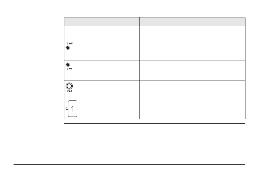
7 Entertainment Function 126
7.1 Selecting an Entertainment Mode 126
7.2 MP3 Input 127
7.3 Aux Input 127
7.4 Setting and Recalling Preset Stations 128
7.5 Manual Tuning of the Frequency 129
7.6 Adjusting Radio Controls 130
8 Service 132
8.1 Virtual Wrench™ 132
8.2 Upgrading Console Software via USB Memory Key 133
8.3 Upgrading Console Software via Virtual Wrench™ 134
8.4 Restoring the Previous Version of Console Software 135
8.5 Backing up the Current Console Software 136
8.6 Backing Up the Current Console Configuration 137
8.7 Restoring the Console Configuration 138
9 Care and Transport 140
9.1 Transport 140
9.2 Storage 141
9.3 Cleaning and Drying 142
Leica mojoRTK, Table of Contents 7
Page 8

Leica mojoRTK, Table of Contents
10 Safety Directions 144
10.1 General Introduction 144
10.2 Intended Use 145
10.3 Limits of Use 147
10.4 Responsibilities 148
10.5 Hazards of Use 149
10.6 Electromagnetic Compatibility EMC 158
10.7 FCC Statement, Applicable in U.S. 161
10.8 ICES-003 Statement, Applicable in Canada 163
10.9 Labelling 164
11 Technical Data 166
11.1 mojoRTK Console Technical Data 166
11.1.1 General Technical Data 166
11.1.2 Tracking Characteristics 169
11.1.3 Positioning Accuracy 172
11.2 mojoRTK Red Antenna Technical Data 173
11.3 mojoRTK Black Antenna Technical Data 176
11.4 mojoRTK Base Station Technical Data 178
11.4.1 General Technical Data 178
11.4.2 Tracking Characteristics 182
11.5 Conformity to National Regulations 185
11.5.1 mojoRTK Console 185
11.5.2 mojoRTK Base Station 188
8
Page 9

12 International Limited Warranty, Software Licence Agreement 190
Appendix A Flow Chart 192
Appendix B Additional mojoRTK Information 196
B.1 Unlock Codes 196
B.2 On Screen Keyboard 198
B.3 Formatting USB Flash Drives 199
Appendix C GNU General Public License 206
Appendix D Glossary 208
Leica mojoRTK, Table of Contents 9
Page 10

Leica mojoRTK, System Overview
1 System Overview
1.1 General mojoRTK System Information
10
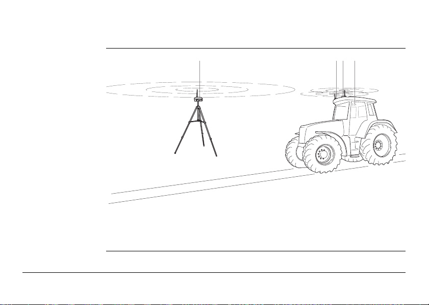
General information
• Leica Geosystems’ mojoRTK is a GPS-based guidance system that provides
assisted steering to various pieces of agricultural equipment.
• The mojoRTK works with a lightweight and easy-to-transfer mobile base station
that provides highly reliable accuracy without incurring GPS subscription fees. The
unique and compact design of the mojoRTK allows you to move it from one piece
of equipment to the next, covering your entire fleet. This is easily accomplished
by the patented design and installation into a DIN slot or radio receptacle.
• Beyond its capabilities of steering accuracy, the mojoRTK also provides remote
service and diagnostics for your guidance system and agricultural machinery,
remote upgrades, and 24/7 service and assistance, eliminating costly on-site
service calls.
Page 11
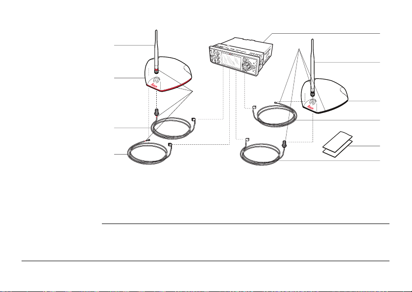
1.2 Components of mojoRTK System
a b c d
mojoRTK_018
mojoRTK components
a) mojoRTK base station
b) mojoRTK Red Antenna
c) mojoRTK Black Antenna
d) mojoRTK console
Leica mojoRTK, System Overview 11
Page 12
Leica mojoRTK, System Overview
a
b
c
d
e
mojoRTK_019
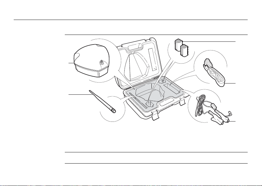
1.3 Unpacking the mojoRTK System
Container for
mojoRTK base
station
12
a) mojoRTK base station
b) Whip antenna
c) Battery GEB221, 2x
Apart from mojoRTK base station, all other parts are delivered in a cardboard box.
d) Shoulder strap for carry case
e) 12V power cable, with crocodile
clips
Page 13
Cardboard box for
e
all other mojoRTK
parts
a
f
b
g
c
d
mojoRTK_020
a) Red whip antenna
b) Red GPS antenna
c) Cable to red whip antenna
d) Cable to red GPS antenna
e) mojoRTK console
f) Black whip antenna
g) Black GPS antenna
h) Cable to black GPS antenna
i) Cleaning wipes
j) Cable to black whip antenna
Leica mojoRTK, System Overview 13
h
i
j
Page 14
Leica mojoRTK, System Overview
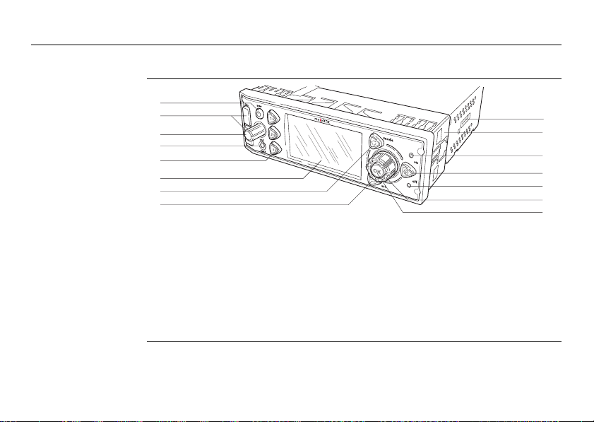
1.4 mojoRTK Console
14
mojoRTK console,
forefront
a
b
c
d
e
f
g
h
mojoRTK_001
a) Power button
b) USB ports
c) Volume control button
d) MP3 plug
e) 1, 2, 3 keys
f) LCD screen
g) Mode key
h) Escape key
i
j
k
l
m
n
o
i) Slot for simcard
j) Mounting sleeve
k) Auto-steer On LED
l) Auto-steer key
m) Auto-steer Off / Ready LED
n) Main dial
o) OK button
Page 15
Buttons, Keys
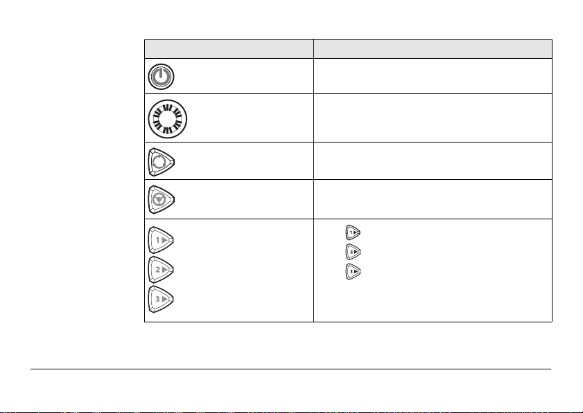
Button, Key Function
Power button Turns unit on or off.
Volume control
button
Mode key Switches between GPS and Entertainment
Auto-steer key Starts/Stops auto-steer system.
1, 2, 3 keys
Leica mojoRTK, System Overview 15
Adjusts radio volume. Pressing the volume
control provides access to stereo system
settings (bass, treble, balance, and fade).
modes.
Press for A-B Setup.
Press for mojo Setup.
Press for Virtual WrenchTM.
1, 2, 3 keys may also be used for up,
down, and tab.
Page 16
Leica mojoRTK, System Overview
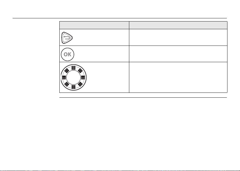
Button, Key Function
16
Escape button Returns to previous menu.
OK button Press to confirm an action or to enter a menu.
Main dial Used to tune radio, select menu options and
change setting values.
Page 17
Screen, LEDs, ports
Module Function
LCD screen Viewing screen for all modes. Refer to "1.5
Auto-steer Off /
Ready LED
Auto-steer On
LED
MP3 plug in Allows an MP3 player to play through the vehicle
mojoRTK Console LCD Screen" for details.
Red LED lights when mojoRTK system is "ready":
Sufficient satellites are found and radio communication to mojoRTK base station is good.
Green LED lights when mojoRTK system is ready
and engaged:
System works and auto-steering is activated.
stereo system.
USB ports Used for data transfer and storage as well as
Leica mojoRTK, System Overview 17
mojoRTK software upgrades.
Page 18
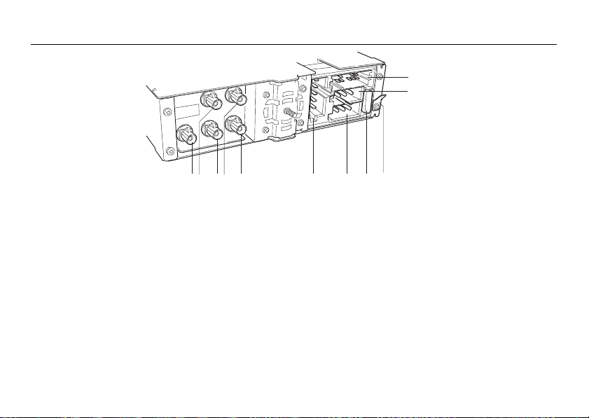
Leica mojoRTK, System Overview
mojoRTK_021
a c e f g h
i
j
k
b
d
mojoRTK console,
rear side
a) Black connector for AM/FM antenna
b) Blue connector for black GPS antenna
(GPS L1)
c) Red connector for red whip antenna
d) Green connector for red GPS antenna
(GPS L2)
e) Purple connector for black whip
antenna
18
f) Connector for service purpose only
g) Power
h) Automotive Blade Fuse (10A, 32V)
i) Grounding connector
j) Connector for CAN and NMEA
k) Connector for speakers
Page 19
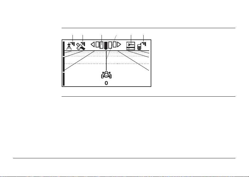
1.5 mojoRTK Console LCD Screen
ab c d e f
mojoRTK_002
mojoRTK screen
a) Base station
b) GPS Satellites
c) Accuracy to Working Line
d) Working Line
e) Virtual Wrench
f) Cellular Phone Signal
Leica mojoRTK, System Overview 19
TM
Page 20
Leica mojoRTK, System Overview
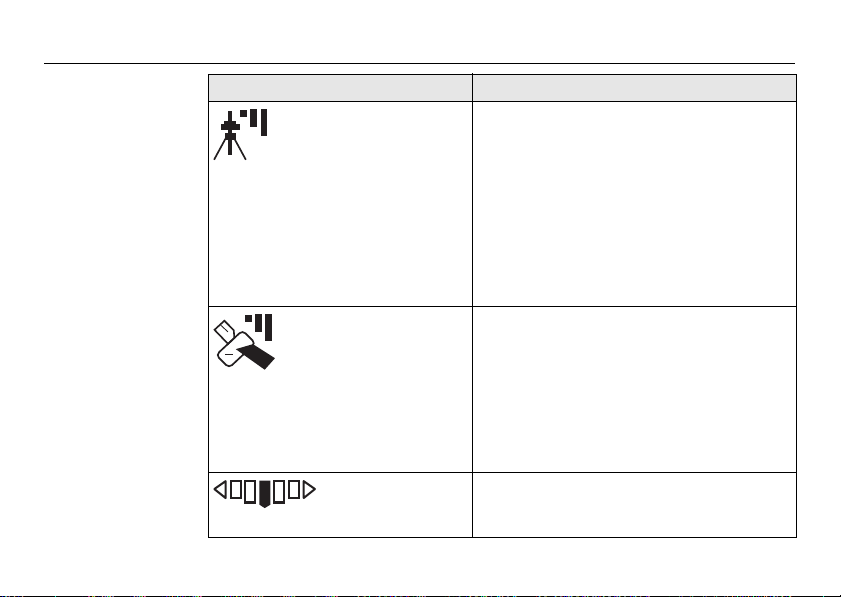
Icon description
Icon Description
Base station Icon • A solid icon with three bars means you
GPS Satellites /
Signal Strength
Accuracy to
Working Line
have an excellent signal from the base
station.
• A solid icon with two bars means you
have a good signal from the base station.
• A solid icon with one bar means you have
a poor signal from the base station.
• A flashing icon with an X means the
system is trying to lock on to the base
station signal.
• A solid satellite icon with three bars
means you have an excellent signal.
• A solid satellite icon with two bars means
you have a good signal.
• A solid satellite icon with one bar means
you have a poor signal.
• A flashing satellite icon means the
system is not seeing enough satellites.
• This icon shows the accuracy of the
system relative to the current working
line while in motion.
20
Page 21
Icon Description
Working Line • The Working Line is in bold, and zero is
displayed below the tractor icon for the
first pass; all other passes are numbered
to the left (L) and right (R) of the center
line. An X through the tractor indicates
roading is enabled.
Virtual WrenchTM• The Virtual WrenchTM in a flashing speech
Leica mojoRTK, System Overview 21
bubble indicates attempting to connect.
• The Virtual WrenchTM in a solid speech
bubble indicates waiting for a technician.
• The Virtual WrenchTM with a box under it
indicates that remote service is operating.
Page 22
Leica mojoRTK, System Overview
Icon Description
Cellular Phone
Signal
22
• A solid icon with three bars means you
have an excellent signal.
• A solid icon with two bars means you
have a good signal.
• A solid icon with one bar means you have
a poor signal.
• A solid icon with an X means there is no
cellular signal. Note that in this condition
Virtual Wrench will be unavailable.
Page 23
1.6 mojoRTK Base Station
Base station overview
a
b
Power
c
ESC
d
e
f
mojoRTK_022
a) Whip antenna
b) Keyboard and display
c) USB Port and protection cap
d) Charger connector
e) Accessories connector
f) Cover for interfaces
g) Cover for battery compartment
h) Battery GEB221, 2 x
i) Thread for tripod screw
Leica mojoRTK, System Overview 23
Charge
OK
g
h
i
Page 24

Leica mojoRTK, System Installation
2 System Installation
2.1 Before Installation
24
General installation information
• The following instructions are to be used as a general guide during the installa-
• Understand that the system will not operate at peak performance if steering
• Install the system in a clean and dry shop environment. Failure to do so may
Installation does not require specialist knowledge. The installer is assumed
to be familiar with the required knowledge by reading and studying the
present user manual including the safety directions. The installer must be
able to use the system in accordance with the user manual. However, Leica
Geosystems recommends that installation of the mojoRTK equipment be
performed by a qualified technician because installation requires making
electrical connections.
tion of the mojoRTK. For more specific instructions, please visit
www.mojoRTK.com to view additional platform information and recommended
vehicle settings.
joints and linkage assemblies are not within the manufacturer’s specifications.
Check for worn steering components by turning the steering wheel. As the
steering wheel is turned, the wheels should begin to move. If results are undesirable, please consult your vehicle manufacturer’s maintenance manual.
cause the system to short or promote product malfunction. Any moisture on
Page 25

the roof of the vehicle will also prevent the antenna mounting tape from
sticking properly.
• Route and secure all cables and wiring to ensure that they do not chafe or rub,
causing premature failure.
• The average installation time will vary, but it should be approximately two to four
hours per vehicle. The time of installation may be more or less, based on vehicle
type.
Leica mojoRTK, System Installation 25
Page 26

Leica mojoRTK, System Installation
2.2 Antenna Installation
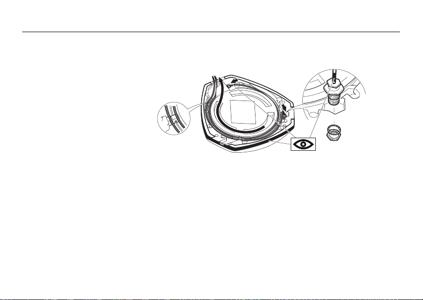
26
Preparations 1. Read all instructions before assembly and installation.
You should also refer to the installation hints specific to your tractor type and/or
steer kit if applicable. These may be obtained at www.mojoRTK.com or may have
been supplied with your system, depending on how you purchased your system.
2. Clean the cab roof to prepare for the mojoRTK Red Antenna and the mojoRTK
Black Antenna. Approved cleaning products are denatured alcohol and Windex®
glass cleaner.
Page 27
Position of the GPS
mojoRTK_023
=
=
d
a
c
c
b
antennas
1. First find the locations that allow the antennas to have a large separation and be
as close to the front of the tractor as possible.
a) Red (Black) antenna offset
b) Center line
c) Measurement dots
d) Antenna separation,
minimum distance 80 cm/32”
Leica mojoRTK, System Installation 27
The antennas must be square with one another, meaning that one antenna
should not be closer to the back of the vehicle than the other.
2. Mark out these locations on the roof of the tractor.
The center dimple on the
antenna is where measurements need to be taken from.
Page 28
Leica mojoRTK, System Installation
1
2
3
4
mojoRTK_024
Prepare GPS
antennas
Start all antenna cable connections by hand before using the wrench to
tighten. Do not overtighten the cable connections. Run the threads to the
end and tighten only 1/8 turn more.
red to red / black to black
1. Connect the color coded cables to mojoRTK black and mojoRTK red antenna black coded cable to black antenna, red to red.
2. Insert the thread of the whip antenna cable as shown, bring on the washer and
fix with the nut. The whip antenna cables are also color coded.
3. Run the cables through the circular slot provided on the bottom side of the cover.
Align each cable with the slot and push it into the slot using the antenna cable
grommets and antenna cable supports provided.
4. You have several options for how you want the cables to exit the antenna cover;
choose whatever works best for your application.
28
Page 29
5. Install a whip antenna on each of the two GPS antennas.
mojoRTK_006
Leica mojoRTK, System Installation 29
Keep in mind that the whip antennas should be mounted on the GPS
antennas to buckle backwards if needed.
The whip antennas are color coded
to the GPS antennas; red to red
and black to black.
Page 30
Leica mojoRTK, System Installation
mojoRTK_004
1
2
3
Mount the GPS
antennas
Use the supplied cleaning wipes to clean the installation area.
.
1. Remove the protective strip on the double-sided tape.
2. Mount the red antenna in its previously marked out position, ensuring that it is
on the right-hand side of the vehicle when looking forward from the operator's seat.
3. Mount the black antenna accordingly on the left-hand side.
30
Page 31

Be careful removing the backing tape from the sticking blocks. Make sure
that you only peel off the tape and do not rip the adhesive from the
backing tape.
Keep in mind that both GPS antennas should mount with the whip
antennas in the forward position.
4. Select the radio/DIN slot that the mojoRTK console will be installed into and
remove either the radio that is there or the blanking plate in the selected slot.
5. Run the antenna cables to the rear of the selected radio/DIN slot for connection
to the mojoRTK console, making sure that there is enough slack in the cables to
reach outside the selected radio/DIN slot.
Leica mojoRTK, System Installation 31
Route the cables through existing grommets if possible; if not, modification
may be required to route the cables to the desired location. If creating a
new entry point, make sure to use a grommet to protect the cables.
The cables must not be cut, kinked, or bent tightly or their performance will
be degraded and may even result in system failure.
Page 32

Leica mojoRTK, System Installation
2.3 mojoRTK Console Installation
2.3.1 Before Installation
32
Before installation Before the console is installed, you must do the following:
• You should also refer to the installation hints specific to your tractor type or
steer kit if applicable. These can be obtained from our website at
www.mojoRTK.com or may have been supplied with your system.
• The make and model of your vehicle will determine how you complete each of
the following tasks.
1. Check or prepare for console power connection:
Depending on the vehicle type, you may already have the correct connectors to
plug into the unit. Otherwise, you will have to use the plugs supplied and hook
them up to the vehicle wiring per the console connection diagram. Refer to
mojoRTK console, rear side, page 18. Please contact Leica Geosystems or your
local reseller for more information.
2. Check or prepare for console speaker connections:
Again, depending on vehicle type, you may already have the correct connectors
to plug into the unit. Otherwise you will have to use the plugs supplied and hook
them up to the vehicle wiring per the console connection diagram. Refer to
mojoRTK console, rear side, page 18. Please contact Leica Geosystems or your
local reseller for more information.
Page 33

3. Install steering cable (CAN bus):
There are many possible combinations for this step, depending on vehicle type
and/or the steer kit used. The cable specific for your vehicle should be purchased
with your system.
Leica mojoRTK, System Installation 33
For more information on each of these important steps, please refer to the installation hints specific to your vehicle or steer kit. Please find these installation hints at
www.mojoRTK.com, How to Guides.
Page 34

Leica mojoRTK, System Installation
2.3.2 mojoRTK Console Installation
34
Console installation
It may be necessary to remove the current radio in the DIN slot. Refer to the user
manual for the existing radio for instructions on its removal.
mojoRTK_026
If removing a current radio, the sleeve in place may or may not fit the
mojoRTK console. Please check the mounting before installation.
Use caution with metal work; it may be sharp and could cause injury if care
is not taken.
1. Carefully remove the console from
its packaging.
2. Push in the locks on the side by
using the removal tools supplied
and slide the mounting sleeve off
the unit.
Page 35

3. Slide the mounting sleeve into the
mojoRTK_027
selected slot, and using the most
suitable bend points on the sleeve,
secure the sleeve into position.
Leica mojoRTK, System Installation 35
There are several different types of mounting on radio systems. Some are
locked only by the DIN sleeve, and others will have a retention nut on the
rear of the radio.
Page 36

Leica mojoRTK, System Installation
mojoRTK_028
36
4. When Virtual WrenchTM is purchased
and your system is equipped with a
GSM or HSDPA internal modem:
Take the SIM card holder out off the
housing and turn it upside down.
Put the SIM card into the SIM card
holder, the chip facing up. Now flip
over the SIM card holder again and
insert it into the SIM card slot.
Page 37

Connecting cables
mojoRTK_029
mojoRTK_030
a
b
c
d
e
1. Pull the vehicle’s AM/FM
antenna cable out of the slot
and connect it to the adaptor
cable from the mojoRTK kit.
2. Pull all the cables that need to be connected to the back of the console, including
the antenna cables, power, speaker, and CAN bus cables, through the sleeve
ready to be connected.
3. Attach all antenna cables to the rear of the console:
a) Black connector with cable from
AM/FM antenna
b) Red connector with cable from
red GPS whip antenna
c) Purple connector with cable
from black GPS whip antenna
d) Blue connector with cable from
black GPS antenna
e) Green connector with cable from
red GPS antenna
Leica mojoRTK, System Installation 37
Page 38

Leica mojoRTK, System Installation
mojoRTK_031
a
b
c
4. Attach all remaining cables to the rear of the console:
38
a) Power cable
b) Speakers cable
c) CAN / NMEA cable
We recommend to attach a grounding cable to the console’s grounding
connector and the other end to a metallic bright part on the tractor.
Page 39

5. Slide the console into the
mojoRTK_008
sleeve and push back until
you hear the clips catching
on both sides.
Leica mojoRTK, System Installation 39
Verify that the console is firmly mounted and cannot move. If movement is
possible, performance may be degraded.
Page 40

Leica mojoRTK, System Installation
mojoRTK_007
Removal of the
mojoRTK console
40
For removal of the mojoRTK console, insert the supplied removal tools in the corners
of the radio faceplate until a click is heard or felt. Apply outward pressure on the
tools and gently pull back at the same time.
Page 41

Leica mojoRTK, System Installation 41
Page 42

Leica mojoRTK, mojoRTK Base Station Operation
3 mojoRTK Base Station Operation
This chapter contains instructions for everyday operation of the mojoRTK base
station.
42
Charging / first-time use
• The batteries must be charged prior to using for the first time because it is delivered with an energy content as low as possible.
• The permissible temperature range for charging is between 0°C to +35°C /+32°F
to +95°F. For optimal charging we recommend charging the batteries at a low
ambient temperature of +10°C to +20°C/+50°F to +68°F if possible.
• It is normal for the battery to become warm during charging. Using the chargers
recommended by Leica Geosystems, it is not possible to charge the battery if the
temperature is too high.
• For new batteries or batteries that have been stored for a long time (> three
months), it is effectual to make only one charge/discharge cycle.
• For Li-Ion batteries, a single discharging and charging cycle is sufficient. We
recommend carrying out the process when the battery capacity indicated on the
charger or on a Leica Geosystems product deviates significantly form the actual
battery capacity available.
Page 43

Operation/Discharging
• The batteries can be operated from -20°C to +55°C / -4°F to +131°F.
• Low operating temperatures reduce the capacity that can be drawn; very high
operating temperatures reduce the service life of the battery.
Warning Batteries not recommended by Leica Geosystems may be damaged if charged or
Leica mojoRTK, mojoRTK Base Station Operation 43
discharged. They may burn and explode.
Precautions:
Only charge and discharge batteries recommended by Leica Geosystems.
Page 44

Leica mojoRTK, mojoRTK Base Station Operation
mojoRTK_032
1
2
3.1 Base Station Setup
44
Fit the batteries,
charging
The batteries must not be removed or added into the mojoRTK base station whilst it
is either in operation or connected to external power.
1. Remove the battery cover with a
straight blade screwdriver.
2. Insert the batteries into the base
station, ensuring they are installed
correctly.
Reinstall the battery cover.
Do not overtighten screws;
tighten to 2.3 Nm/20 in-lb.
Page 45
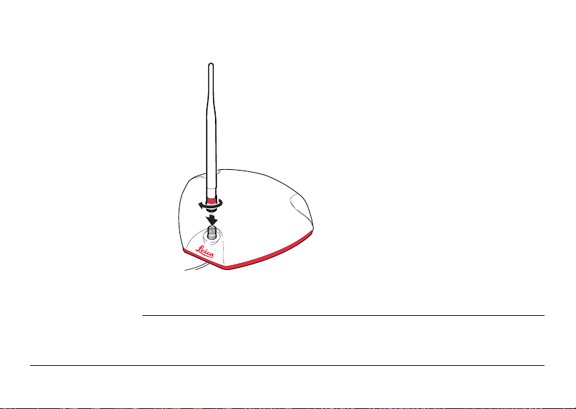
3. Screw the whip antenna on top of the
mojoRTK_005
3
4
5
base station.
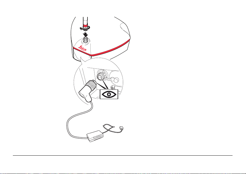
4. Connect the plug of the external charger
into the back of the base station. This
plug is keyed. Do not force-fit the plug.
Once the plug is connected, handtighten the finger nut to fasten the
cable to the base station.
5. Plug the base station charger into an
outlet and charge for 24 hours.
When charging is complete, remove the
charging cable.
Leica mojoRTK, mojoRTK Base Station Operation 45
Page 46

Leica mojoRTK, mojoRTK Base Station Operation
46
Base station setup
mojoRTK_009
1. Pull open the tripod lever locks, two
2
per leg, and extend the tripod legs
to your needs. The locks can hold
the leg at any length.
2. Loosen the hand screw at the top
of the tripod and extend the top
3
4
section, set the height to the
desired level, and lock down by
tightening the hand screw.
3. Lock the legs in the desired position
using the lock screw located on the
center support tube.
4. Screw the base station on top of
the tripod.
1
Page 47

Leica mojoRTK, mojoRTK Base Station Operation 47
• Standard use setup would configure the tripod as high as possible with the legs
at maximum distance.
• Sandbag or weight the tripod to improve the stability of the base station.
• Protect the base station from animals and farm equipment.
• Be aware that other equipment may interfere with the base station. This includes
but is not limited to generators, radio transmitters, electrical equipment, and
other base stations.
• The base station should be mounted on the tripod or be fixed in the open. It
should not be placed under or near roofs, trees, large bodies of water, or
awnings. Any obstacle may affect GPS and radio transmissions.
• The base station requires line of sight to the console. Vehicles, buildings, solid
fences, or trees can all affect operation.
• When using the base station as a permanently installed reference station a
power cable can be purchased for power supply and no batteries are needed.
Please contact Leica Geosystems or your local reseller for more information.
Page 48

Leica mojoRTK, mojoRTK Base Station Operation
3.2 Base Station Operation
Keyboard, display
mojoRTK_003
abcde f
Power LED: Red LED lights when mojoRTK system is working.
Charge LED: Lights orange, when base station batteries are being charged.
Flashes orange, when base station batteries are fully charged.
48
a) Power button
b) Escape / return button
c) Scroll up button
d) Scroll down button
e) OK button/Selection
f) Control LEDs for power and
charge status
First time use When turned on for the very first time a setup wizard will come up on the base
station. It has two items in the following order:
• Language; refer to "3.2.1 How to Change the Language"
• Region; refer to "3.2.2 Region Selection"
Page 49

Operation 1. Ensure base station setup has been completed and batteries are fully charged.
2. Push and hold the power button for two or three seconds until the screen
comes on.
3. The screen will become active and begin a count down as it searches for satellites. It will then go to the main menu and to find the position of the base station.
4. While the base station is calculating the position, the screen will read fixing…pls
wait.
5. In a few minutes from when is pushed, the screen will go from fixing…pls
wait
to Position Fixed.
Initial startup of the base station can take up to several minutes to acquire
due to downloading the GPS almanac. Also, startup times can be increased
after long storage periods.
6. At this time, the base station has a fixed position.
7. Now check the radio channel and ensure it is the same as the mojoRTK console.
It is suggested to start with channel 0 unless interference is detected.
Leica mojoRTK, mojoRTK Base Station Operation 49
If the base station can not get a GPS fix in two minutes it may enter a quiet mode
where the system will appear to shut down and restart. This can happen a maximum
of three times.
Page 50

Leica mojoRTK, mojoRTK Base Station Operation
3.2.1 How to Change the Language
50
Change the
language, step-bystep
1. Using , scroll to Settings and press .
2. Using , scroll to Language and press .
3. Using , select a language and press .
4. To leave this menu, press the Escape button until you return to the main
screen.
3.2.2 Region Selection
Region selection,
step-by-step
1. Using , scroll to Region and press .
2. Using , scroll to Country and press .
3. Using , select the region you are operating in and press .
• Selecting the correct country may help to increase the optimal satellite search.
• By selecting the wrong country, you may be breaching regulatory requirements.
The base station will program the integrated radio and restart. The base
station is then ready to provide position.
Page 51

3.2.3 Changing the Radio Channel
Change the radio
channel, step-bystep
Leica mojoRTK, mojoRTK Base Station Operation 51
1. Use the Scroll Up and Down buttons to scroll to Channel and press the
OK button .
2. The current channel the base station is set to will be displayed.
3. To change the channel from 0-4 Europe (0-9 North America and Australia), use
and press on your selection.
4. The base station will say channel changed and is ready for use.
Remember the channel setting. Ensure the same channel setting is entered on your
mojoRTK console or the system will not work.
Page 52

Leica mojoRTK, mojoRTK Base Station Operation
3.2.4 How to Activate / Deactivate GLONASS
52
Activate / deactivate GLONASS,
step-by-step
GLONASS is activated by default, it is recommended that it be deactivated if the
mojoRTK console is not enabled to receive GLONASS as doing so will increase the run
time of the base station whilst on batteries.
GLONASS is the Russian version of the US-run GPS system. The mojoRTK
can be activated to make use of the GLONASS satellites. To utilise the
GLONASS satellite software upgrade, GLONASS must be enabled on the
mojoRTK console.
1. Using , scroll to Settings and press .
2. Using , scroll to GLONASS and press .
3. Using , enable or disable GLONASS and press .
If this option is selected, the base station will reboot. This will take approximately one minute.
4. To leave this menu, press until you return to the main screen.
Page 53

3.2.5 Adjusting Contrast
Adjust contrast,
step-by-step
Leica mojoRTK, mojoRTK Base Station Operation 53
1. Using , scroll to Settings and press .
2. Using , scroll to Contrast and press .
3. Using , select % of contrast and press .
Page 54

Leica mojoRTK, mojoRTK Base Station Operation
3.2.6 Software Upgrade
54
Software upgrade,
step-by-step
When performing a software upgrade, ensure that the batteries are
charged and the base station is connected to external power. It is vitally
important that the device is not turned off during an upgrade.
Refer to "B.3 Formatting USB Flash Drives" for important information about
using USB drives with the mojoRTK products.
1. Using , scroll to Service and press .
2. Using , scroll to Software Upgrade and press .
3. Insert the USB stick containing the new software into the USB port.
4. Press to select the software version displayed. If the USB stick contains
multiple software versions, select the desired version.
5. The current and new software versions will be displayed. Press to proceed.
A software upgrade consists of a number of steps that will be displayed on
the screen including Checking, Erasing, Installing, Power Down, and
Loading. This will take a few minutes.
6. If a software upgrade is not your choice, press until you return to the main
screen.
Page 55

3.2.7 Rollback Software
Rollback software,
step-by-step
Leica mojoRTK, mojoRTK Base Station Operation 55
Rollback software is only available when an earlier version of software was previously
installed on the base station.
When performing a software rollback, ensure that the batteries are
charged and the base station is connected to external power. It is vitally
important that the device is not turned off during rollback.
1. Using , scroll to Service and press .
2. Using , scroll to Rollback Software and press .
3. Using , select Yes or No to select the software version and press to
select.
Rollback software consists of a number of steps that will be displayed on
the console, including Rebooting, Power Down, and Loading. This will take
approximately one minute.
Page 56

Leica mojoRTK, mojoRTK Base Station Operation
3.2.8 How to Reset Defaults
56
Reset defaults,
step-by-step
1. Using , scroll to Settings and press .
2. Using , scroll to Reset Defaults and press .
3. To reset defaults, press again.
If this option is selected, the base station will reboot. This will take approximately one minute.
4. To leave this menu, press until you return to the main screen.
3.2.9 System Information
Access system
information, stepby-step
1. Using , scroll to Service and press .
2. Using , scroll to System Info and press .
3. By using , you can view the serial number, firmware version and software
version, unlock code status, and current position.
4. Once viewed, press until you return to the main screen.
Page 57

3.2.10 Additional Features
Use additional
features, step-bystep
Leica mojoRTK, mojoRTK Base Station Operation 57
Please contact Leica Geosystems or your local reseller for more information.
This menu is used for manual input of the unlock code for purchased
product features, for example Additional Data Formats.
1. Using , scroll to Service and press .
2. Using , scroll to Add Features and press .
3. Use to find each digit or letter and press . Repeat until the full code
has been entered; use to go back a space if required.
4. Check the number and press if correct.
The base station may reboot to implement the new feature.
Page 58

Leica mojoRTK, mojoRTK Base Station Operation
3.2.11 Selecting Data Format (if available)
58
General information
Select data format,
step-by-step
The Additional Data Formats option is available at a cost with an unlock code.
The options are:
• mojo1 [default]
• CMR
• RTCM3.0
Different data formats are used for operating a mojoRTK console with other GPS
devices that do not accept the proprietary mojo1 format that is used by default.
Without the unlock code the option for this menu is not shown.
1. Using , scroll to Settings and press .
2. Using , scroll to Data Format and press .
3. Using , select the desired format and press .
Please contact Leica Geosystems or your local reseller for more information.
Page 59

3.2.12 Setting Position Mode (if available)
General information
Setting position
mode, step-bystep
Leica mojoRTK, mojoRTK Base Station Operation 59
This option is available at a cost with an unlock code.
The options are:
• Snap to Previous [default]
• Fixed Position
• First Fix
• Averaged
Without the unlock code the option for this menu is not shown.
1. Using , scroll to Settings and press .
2. Using , scroll to Position Mode. This will tell you what type of position fix
you are using.
3. If you want to change the position type, use and press .
4. If you do not want to change the position type, press to get back to the main
menu.
Please contact Leica Geosystems or your local reseller for more information.
Page 60

Leica mojoRTK, Running the mojoRTK Console for the First Time
S mojoRTK 001
60
4 Running the mojoRTK Console for the First Time
4.1 Setting up the mojoRTK Console
Set up the console Before starting the mojoRTK console in the tractor:
• Have the base station set up and running with a fixed position as described in
chapter "3 mojoRTK Base Station Operation".
• Note the channel number that the base station is running on (by default this is
channel 0).
1. Press and hold for 2-3 seconds and the unit
will turn on and the Leica logo screen will come
up.
2. Press to continue.
Introduction
Welcome to the
mojoRTK Setup Wizard
Press Ok to continue
Ok
Page 61

The mojoRTK Setup Wizard is actually three wizards run one after the other:
• System Wizard,
• Vehicle Wizard, and
• Base Radio Wizard.
These wizards guide you through the setup process.
Leica mojoRTK, Running the mojoRTK Console for the First Time 61
Page 62

Leica mojoRTK, Running the mojoRTK Console for the First Time
4.2 System Wizard
62
System Wizard,
step-by-step
1. Use the main dial to select the Language and press .
2. Use the main dial to select Region and
press .
Select region
North America
S_mojoRTK_002
3. Use the main dial to select the measurement
units (US Standard or Metric) and press .
Select units
US Standard
S_mojoRTK_003
Region
Ok
Units
Ok
Page 63

4. Use the main dial to adjust the display contrast
to your liking. The contrast changes as you turn
Contrast
the main dial.
Press once you have the desired setting.
62%
S_mojoRTK_004
5. Use the main dial to adjust the display backlighting brightness and press
when you have the desired setting.
Leica mojoRTK, Running the mojoRTK Console for the First Time 63
Page 64

Leica mojoRTK, Running the mojoRTK Console for the First Time
4.3 Vehicle Wizard
64
Vehicle Wizard,
step-by-step
1. The Vehicle Wizard starts with the mojoRTK orientation. The mojoRTK orientation
describes the orientation of the console in the tractor.
90°
0°
mojoRTK_010
For the tests that follow, you will need to drive the tractor and be in an open area
with room to move.
-90°
Press and adjust the number to
represent how the system is mounted
in the cab.
If the system is mounted directly in
front of you (when sitting in the
seat), the setting should be 0°. If the
unit is at 90° on your right, then the
setting is 90. If the unit is at 90° on
your left-hand side, then the value is
-90°. Press when you have
entered the correct value.
Page 65

2. Drive the tractor to flat ground and press
when fully stopped. The mojoRTK console will
automatically perform a terrain tuning operation.
Do not move vehicle until instructed. To
ensure accurate tuning, it is advised that both
front wheels are clearly marked on the ground.
Terrain Compensation
Drive to flat ground and
press OK once stopped.
Skip OK
S_mojoRTK_005
Terrain Compensation
Tuning in progress. Do
not move until finished.
S_mojoRTK_006
Leica mojoRTK, Running the mojoRTK Console for the First Time 65
Page 66

Leica mojoRTK, Running the mojoRTK Console for the First Time
S_mojoRTK_008
66
3. When complete, the console will ask you to turn
the vehicle around. Turn the vehicle around 180°
back to the same position. Press when back
in the same spot and fully stopped.
Terrain compensation tuning will continue. Do
not move vehicle until completed.
4. Console will say Tuning complete. Vehicle may
now be moved.
Press to continue.
Terrain Compensation
Turn the vehicle
around. Press OK after
stopping.
S_mojoRTK_007
OK
Terrain Compensation
Tuning in progress. Do
not move until finished.
Terrain Compensation
Tuning complete.
Updates will be
required if you receive
an Accuracy Warning.
S_mojoRTK_046
OK
Page 67

5. The next screen is for compass tuning, and the
console will ask you to drive to a flat and open
location. Press once you have done this.
Be aware that compass tuning can fail if:
• the speed of the vehicle is too high or not constant while tuning.
• the tuning is conducted under, over or near, a metallic mass.
• the tuning is performed, under, over or near, power lines.
Leica mojoRTK, Running the mojoRTK Console for the First Time 67
You need sufficient space to perform the next tuning operation.
Compass Tuning
Please drive to a flat,
open area. Press OK
when ready.
Skip OK
S_mojoRTK_009
Page 68

Leica mojoRTK, Running the mojoRTK Console for the First Time
S_mojoRTK_010
S_mojoRTK_011
68
6. The console will ask you to drive slowly in circles.
Drive slowly (below 3.2 km/h or 2 mph) in circles
in one direction until the console shows that
both compass tuning operations (parts 1 and 2)
are complete.
The console will say Compass tuning
successful. Press to continue. You can now
stop the vehicle.
Compass Tuning
Please drive slowly in
circles. Tuning part1 in
progress.
Compass Tuning
Please drive slowly in circles.
Tuning part 2 in
progress.
Compass Tuning
Compass tuning
successful.
OK
S_mojoRTK_012
Page 69

7. Use the main dial to select the vehicle type or
steer kit for your installation and press . You
should see a message stating the steer kit
communications status, for example CAN Bus
Connected, Steering Kit Active.
There may be extra steps required at this point or even later depending on
which vehicle type or steer kit you select.
8. The next screen explains that you are about to enter the Antenna Separation.
Make sure that you have measured the distance between the center of the black
and the red GPS antenna accurately. Refer to "Position of the GPS antennas",
page 27. Press to continue.
Vehicle Type
Select vehicle type
None
S_mojoRTK_013
OK
Leica mojoRTK, Running the mojoRTK Console for the First Time 69
Measure from the molded dot in the center on the antenna.
Page 70

Leica mojoRTK, Running the mojoRTK Console for the First Time
S_mojoRTK_014
70
9. Use the main dial and/or the 1.2.3 buttons to
enter the spacing between the black and the red
GPS antennas on the roof and press when
done.
Ant. Separation
0.82
m
10. The next screen explains that you are about to enter the red antenna offset.
The red antenna offset is the distance from the center line of the tractor to the
center of the red antenna. This distance should be half the antenna separation
when the antennas are installed correctly. Measure the red antenna offset to
ensure the best system performance. Refer to "Position of the GPS antennas",
page 27. Press to continue.
11. Use the main dial and/or the 1.2.3 buttons to
enter the measured red antenna offset on the
roof. Press when complete.
S_mojoRTK_015
Red Ant. Offset
0.41m
Page 71

12. The next screen explains that you are about to enter the Vehicle Height. The
S_mojoRTK_016
vehicle height is the measured distance from the ground to the bottom of the
red GPS antenna. Press to continue.
13. Use the main dial and/or the 1.2.3 buttons to
enter the vehicle height. Press when done.
Vehicle Height
2.95m
Leica mojoRTK, Running the mojoRTK Console for the First Time 71
Page 72

Leica mojoRTK, Running the mojoRTK Console for the First Time
4.4 Base Radio Wizard
72
Base Radio Wizard,
step-by-step
1. The Base Radio Wizard starts with Base Radio Channel. Use the main dial to
select the base radio channel. It is suggested to start with channel 0 unless inter-
ference is detected. Press when done.
The channel on the base station needs to be the same as the console. For information about changing the channel, refer to "3.2.3 Changing the Radio Channel".
2. The screen will then display Base Radio Status. This is the base connection
status.
• If the country has been changed, this screen may not appear. If base status is
not good, try changing the channel on the base station. Press when done.
• The base station must be running and on the same channel for good signal
strength and base data reception.
3. If base status is not good, try changing the channel on the base station first and
then on the mojoRTK console by pressing the Escape button on the console
to go back to base channel setting menu. Ensure that the base station and
console are configured to the same region.
Page 73

4.5 Completion of Initial Setup Wizard
Setup Wizard
completion, stepby-step
Leica mojoRTK, Running the mojoRTK Console for the First Time 73
1. At this point, the display will say Setup Complete, setup has completed. Press
to restart the device.
2. Press to restart the console.
3. As the system shuts down, it will program some of the configurations into the
unit. Please be patient and do not disconnect power during this stage.
4. The system will shut itself down and restart itself. If for any reason it doesn’t
start back up by itself, turn it back on with .
You may be asked to perform an additional tuning operation for steering; this varies
from kit to kit. Refer to www.mojoRTK.com for your specific steering kit tuning.
Page 74

Leica mojoRTK, Tuning
5 Tuning
74
General information
The tuning of the mojoRTK is preloaded based on your selected vehicle/steering kit
type and should be a reasonable starting point for tuning refinement. To refine the
tuning of the system, there are four parameters:
• Sensitivity
• Aggressiveness
• Overshoot
• Speed Adjust
For optimal performance, the system tuning must be refined for your steering
kit/vehicle.
Page 75

5.1 Tuning Wizard
General information
Leica mojoRTK, Tuning 75
Sensitivity, Aggressiveness, Overshoot, and Speed Adjust can be found in the Vehicle
Tuning Wizard.
• Get the following parameters right at 5 km/h / 3 mph and then you should only
have to adjust speed.
• Settings in the Tuning Wizard are applied immediately but not saved unless
is pressed.
• Some steering kits/vehicles do not require tuning, so this wizard may be replaced
by a specific one for your selected steering kit/vehicle.
Page 76

Leica mojoRTK, Tuning
5.2 Sensitivity
76
Setting the Sensitivity
The sensitivity will control the rate that the tractor turns and how sensitive it is when
it is on the line. Sensitivity should be the only parameter that you need to adjust to
adapt the control performance to the current working conditions after the tuning
refinement is done.
1. Sensitivity is the first item in the menu dialogue.
Press to display the menu.
2. Use the main dial to move between menu items
and press to display the Sensitivity.
Sensitivity 85%
Line Spacing 5.00m
Roading Yes
Base Channel 1
S_mojoRTK_018
Menu
Sensitivity
3. Use the main dial to adjust the Sensitivity, and
press to save the setting.
0cm
85
Page 77

Explanation • The sensitivity can be set between 50% and 150%. The standard setting is 100%.
150%
100%
50%
mojoRTK_011
• In general, higher sensitivity is for slower travelling speed, lower sensitivity for
faster speed.
• Different sensitivity settings and their approach to the working line:
Leica mojoRTK, Tuning 77
Page 78

Leica mojoRTK, Tuning
5.3 Aggressiveness
78
Setting the aggressiveness
The aggressiveness will control the rate that the tractor attacks the line and how well
it holds the line. When adjusting the aggressiveness, look for these qualities:
1. Use the main dial to adjust the Aggressiveness,
and press to save the setting.
Aggressiveness
0cm
Explanation Different aggressiveness settings and their approach to the working line:
150%
100%
50%
mojoRTK_012
The standard setting is 100%.
115
Page 79

5.4 Overshoot
Setting the overshoot
The overshoot value will control the rate at which the tractor will drive at the line and
the rate that the tractor will round off as it approaches the line. A low value will cause
the tractor to hold off the line longer while a high value will cause the tractor to
converge quickly and possibly drive past the line.
1. Use the main dial to adjust the Overshoot, and
press to save the setting.
S_mojoRTK_022
Overshoot
120
0cm
Leica mojoRTK, Tuning 79
Page 80

Leica mojoRTK, Tuning
150%
100%
50%
mojoRTK_013
Explanation Different overshoot settings and their approach to the working line:
The standard setting is 100%.
80
Page 81

5.5 Speed Adjust
Setting the speed
adjust
Leica mojoRTK, Tuning 81
The speed adjust should be used to fine tune the performance of the control system
for higher speeds than the tuning speed of 5 km/h / 3 mph. Typically, the vehicle can
steer side to side at higher speeds, and this can be resolved by reducing the speed
adjust. If the vehicle does not hold the line as desired at the desired speed, then
increase the speed adjust.
1. Use the main dial to adjust the Speed Adjust,
and press to save the setting.
The speed adjust has no effect at or below 5 km/h / 3 mph.
.
Speed Adjust
120
0cm
Page 82

Leica mojoRTK, Tuning
5.6 Tuning Tips
82
General tuning tips When dealing with the tuning, each parameter must be treated separately, even
In-depth tuning
tips
though they may have interactions between them.
When tuning for:
• turning rate and twitch on the line, use Sensitivity.
• line holding, oscillations, and line approach speed, use Aggressiveness.
• amount of overshoot or undershoot, use Overshoot.
• variation over speed, use Speed Adjust.
Get these parameters right at 5 km/h / 3 mph, and then tune for higher speeds with
only the Speed Adjust.
Symptom Resolution
Tractor is too slow to approach the line. Increase the Aggressiveness.
Tractor is too fast to approach the line or
the tractor oscillates.
Tractor straightens up before it gets to
the line.
Decrease the Aggressiveness.
Increase the Overshoot.
Page 83

Symptom Resolution
Tractor drives past the line then comes
back onto to the line.
Tractor turns very slowly to drive toward
the line.
Tractor turns very aggressively to drive
toward the line and twitches when on
the line.
Tractor oscillates only at higher speeds. Reduce the Speed Adjust.
Tractor does not hold the line at higher
speeds.
Leica mojoRTK, Tuning 83
Decrease the Overshoot.
Increase the Sensitivity.
Reduce the Sensitivity.
Increase the Speed Adjust.
Page 84

Leica mojoRTK, Normal System Operation
6 Normal System Operation
6.1 Starting up the System
84
Start up, step-bystep
1. Start the base station in an open area and within line of sight of the console.
Refer to "3.1 Base Station Setup" for more information.
2. Press and hold for 2-3 seconds to start the mojoRTK console in the vehicle.
Wait about one minute for the system to start.
3. The mojoRTK controller will be ready for use when the Auto-steer Off / Ready
LED turns red.
The Auto-steer Off / Ready LED is the main way to know if the system is ready to
steer.
Page 85

6.2 Setting Waypoints (or A-B Points)
General information
Setting waypoints,
step-by-step
Leica mojoRTK, Normal System Operation 85
The waypoints are used to define a line in the field that all working lines will be
parallel to. Waypoints need to be set before auto-steer can be used.
Before you can set waypoints, the system must have a good position fix. If
auto-steer is not engaged and the system has a good position fix, the
Auto-steer Ready LED will be lit.
1. Position your vehicle in the field where you want to start (Waypoint A).
2. Press twice to enter the setup for
Waypoint A. Press to set Waypoint A or
press to cancel.
S_mojoRTK_024
3. Drive to your desired ending point in the field (Waypoint B).
[OK] to set
point A
Press
Page 86

Leica mojoRTK, Normal System Operation
86
If wayline storage is activated on your mojoRTK console please refer to "6.14 Wayline
Storage".
The minimum distance should be at least 30 metres (100 feet). The greater
the distance between the waypoints, the better the accuracy of the
working line. Where possible, set the waypoints at either end of the field.
4. Press to set Waypoint B.
S_mojoRTK_025
Press
[OK] to set
point B
Page 87

6.3 Setting the Line Spacing
General information
The line spacing sets how far apart the working lines are. This distance is essentially
the width of the implement you are using.
Setting line
spacing, step-bystep
1. From the main navigation screen, press to enter the main menu and select
Line Spacing by pressing .
2. If measurement is correct as it is, press .
3. Use or the main dial to set the line
spacing according to the measured implement
width - from end tool to end tool.
Once you have set the whole units to the desired
Line Spacing
12 .00m
value press , this will then allow you to
change the fractional units (after the decimal
point).
S_mojoRTK_027
4. Press to confirm the new setting.
Leica mojoRTK, Normal System Operation 87
Page 88

Leica mojoRTK, Normal System Operation
6.4 Setting the Implement Offset
88
General information
Setting implement
offset, step-bystep
The implement offset is used when the center of the implement is not in line with
the center of the vehicle. It is used to adjust the vehicle paths for offset implements.
1. From the main steering screen, press to enter the main menu.
2. Turn the main dial to select Settings, and then press .
3. Use the main dial to select Guidance, and then press .
4. Use the main dial to select Implement Offset. The current offset is shown on
the right side of the screen. Press to change the implement offset.
5. Use or the main dial to set a new
implement offset.
Implement Offset
10 .00m
Right
S_mojoRTK_029
Page 89

Leica mojoRTK, Normal System Operation 89
When you are sitting in the seat of the vehicle, if the center of the implement is 1 m/3 ft from the center of the vehicle to your right, the implement
offset will be 1.00 m/36.00” Right. Likewise, if the implement is 1 m/3 ft
to the left of the center of the vehicle, the implement offset will be
1.00 m/36.00” Left.
6. Press to confirm the new offset.
7. To exit without applying the new setting, press until you return to the main
steering screen.
Page 90

Leica mojoRTK, Normal System Operation
6.5 Using Auto-steer
90
General information
Using auto-steer,
step-by-step
• Refer to "6.6 Roading" for details on the Roading safety feature.
• Certain vehicles/steering kits may have a separate engage switch that will replace
If auto-steer is not engaged and the system has a good position fix, the red
light to the right of the main dial will be lit.
1. Before you can engage auto-steer, the system must have a good position fix.
2. Steer your vehicle to a desired line and press while in motion. The steering
system will now guide the vehicle.
3. To disengage the automatic steering system, press .
Auto-steer will also disengage if you turn the steering wheel to the left or right
(if this is supported in your vehicle) or you come to a complete stop.
the functionality of the mojoRTK console engage button.
Page 91

6.6 Roading
General information
Turn roading off There are two ways to turn Roading off:
Leica mojoRTK, Normal System Operation 91
The Roading feature is a safety tool that is designed to prevent accidentally engaging
auto-steer when auto-steer should not be engaged, such as when roading or working
near obstacles.
Each time the mojoRTK console is turned on, Roading is turned on too, which
will disable auto-steer.
• From the navigation screen, press to enter the menu, scroll down to
Roading, and press .
Press to get back to the navigation screen.
• When you try to engage auto-steer with Roading turned on, the console will ask
you to confirm that you want to turn Roading off. If you want to use auto-steer
and therefore turn Roading off, turn the main dial counter-clockwise to Yes and
press .
If you do not want to turn Roading off, for example because you accidentally hit
, press .
The Roading feature must be enabled at all times when activation of guidance could
cause damage or injury, for example when travelling on a road.
Page 92

Leica mojoRTK, Normal System Operation
6.7 mojo Feature
92
General information
Using mojo
feature, step-bystep
The mojo feature allows you to automatically adjust the A-B line with respect to your
current position.
1. Press to display button options.
2. Press again. You will be asked to drive to the
correct position.
A-B
mojo
mojo Field Offset
Manually drive vehicle
to the correct position for
the current line and
press OK
S_mojoRTK_031
GG
Page 93

3. Press once you are in position, and the A-B line will be adjusted to your
current position.
Leica mojoRTK, Normal System Operation 93
Page 94

Leica mojoRTK, Normal System Operation
S_mojoRTK_047
6.8 Setting the Field Offset Manually
94
Setting field offset
manually, step-bystep
The field offset is used to move the original AB line to a new desired location. This
will be used most often if the base station has been moved. The field offset can be
manually set or automatically set. This section describes the manual setting.
1. From the main steering screen, press to enter the main menu.
2. Turn the main dial to select Settings, and then press .
3. Use the main dial to select Guidance, and then press .
4. Use the main dial to select Field Offset. The current offset is shown on the right
side of the screen. Press to change the field offset.
5. Use or the main dial to set a new field
offset.
Field Offset
1.00m
Page 95

6. Press to confirm the new offset.
7. To exit without applying the new setting, press until you return to the main
steering screen.
Leica mojoRTK, Normal System Operation 95
Page 96

Leica mojoRTK, Normal System Operation
6.9 Setting the Vehicle Sensitivity
96
General information
Setting vehicle
sensitivity, stepby-step
The Vehicle Sensitivity changes the sensitivity of the tractor steering. The higher the
sensitivity, the more quickly the vehicle will respond; the lower the sensitivity, the
more slowly the vehicle will respond when it steers.
1. From the navigation screen, press to enter Menu.
2. Turn the main dial to select Sensitivity, and then press .
3. Adjust the Sensitivity level with the main dial or
and .
S_mojoRTK_033
Sensitivity
50%
4. Press to confirm the new setting.
5. When you are finished, press to save the selected value, or press until
you return to the navigation screen if you wish to keep the old setting.
Page 97

6.10 Viewing Serial Numbers
Viewing serial
numbers, step-by-
1. From the navigation screen, press to enter Menu.
step
2. Turn the main dial to select Service, and then press .
3. Use the main dial to select Statistics, and then press .
4. Use the main dial to select Serial Numbers, and
then press .
Serial Numbers
Article 675502
Unit Number 000107
GSM355633000697994
ME3 Serial BYY08091198
S_mojoRTK_035
5. Use the main dial to scroll up and down to see all of the serial numbers stored in
the system.
6. To exit the menu, press until you return to the Navigation screen.
Leica mojoRTK, Normal System Operation 97
Page 98

Leica mojoRTK, Normal System Operation
6.11 System Rescue
98
General information
Restore the
language
Restore the
contrast
Reset factory
settings
System shut down For a non-responsive system, hold down for 10 seconds to power down. The
If you accidentally change the language and can’t understand the menus to change
it back or you adjust the contrast of the screen so that you can’t see the display
anymore, there are special key sequences that you can press to recover the default
language and contrast.
To restore the language, press three times followed by three times followed
by three times, within 8 seconds, followed by .
To restore the contrast, press three times followed by three times followed
by three times, within 8 seconds, followed by .
To enable the factory reset option in the main menu, press three times followed
by three times, followed by three times, within 8 seconds, followed by .
system will shut down as the button is released.
Page 99

6.12 Network RTK
Benefits The Network RTK feature allows the mojoRTK console to be operated without the
Limitations Network RTK can only be used when a good connection to the internet is present.
Leica mojoRTK, Normal System Operation 99
This is an optional software upgrade to the base model in all regions.
need for a local base station. The RTK corrections are instead received from a
network provider over the internet using the console’s internal modem. The Network
RTK feature replaces the local base station with a network of permanent base
stations operated by a network provider.
Network RTK offers very quick convergence times (similar to using the mojoRTK base
station) compared to other correction sources available.
The Network RTK base stations are survey quality and mounted in fixed positions,
offering repeatability from year to year.
Internet connections are only supported through the mojoRTK console’s internal
modem and so cellular coverage is required in all areas you intend to operate guidance.
In order to use Network RTK, it is necessary to be within the bounds of the network
being used. Only correction streams providing CMR, CMR+ or RTCM 3 format corrections are supported. GLONASS is only supported with the RTCM 3 format.
Page 100

Leica mojoRTK, Normal System Operation
Required items • Network Upgrade unlock code
• Network Data Plan unlock code
• Subscription to local Network RTK provider
Please contact Leica Geosystems or your local reseller for further details on activating
this optional software module.
Configuration For information about the installing the unlock codes refer to "B.1 Unlock Codes"
100
Using the On
Screen Keyboard
Setting up Network
RTK, step-by-step
For information about the On Screen Keyboard (OSK) refer to "B.2 On Screen
Keyboard".
1. Switch on the mojoRTK console and wait for a basic GPS fix to be achieved (satellite icon shows one or more bars).
2. The mojoRTK console needs to have good internal modem signal strength (1 or
more bars).
3. If you are not on the navigation screen then press until it comes up.
4. Press to enter the main menu.
5. Use the main dial to scroll down to Base Channel.
 Loading...