

Page 1
Instruction Manual
Leica AutoStainerXL, V2.1 English – 10/2002
Always keep this manual near the instrument!
Read carefully prior to operating the instrument!
Leica
AutoStainer XL
Automated slide stainer
Page 2

Page 3

NOTE
The information, numerical data, notes and value
judgments contained in this manual represent the
current state of scientific knowledge and stateof-the-art technology as we understand it following thorough investigation in this field.
We are under no obligation to update the present
manual according to the latest technical developments, nor to provide our customers with additional copies, updates etc. of this manual.
For erroneous statements, drawings, technical
illustrations etc. contained in this manual we exclude liability as far as permissible according to
the national legal system applicable in each individual case. In particular, no liability whatsoever
is accepted for any financial loss or consequential damage caused by or related to compliance
with statements or other information in this
manual.
Statements, drawings, illustrations and other information as regards contents or technical details of the present manual are not to be considered as warranted characteristics of our
products.
These are determined only by the contract provisions agreed between ourselves and our customers.
Leica reserves the right to change technical
specifications as well as manufacturing processes without prior notice. Only in this way is it
possible to continuously improve the technology
and manufacturing techniques used in our products.
This document is protected under copyright laws.
Any copyrights of this document are retained by
Leica Microsystems Nussloch GmbH.
Any reproduction of text and illustrations (or of
any parts thereof) by means of print, photocopy,
microfiche, web cam or other methods – including any electronic systems and media – requires
express prior permission in writing by Leica
Microsystems Nussloch GmbH.
For the instrument serial number and year of
manufacture, please refer to the name plate at
the back of the instrument.
© Leica Microsystems Nussloch GmbH
Published by:
Leica Microsystems Nussloch GmbH
Heidelberger Str. 17 - 19
D-69226 Nussloch
Germany
Phone: +49 (0)6224 143-0
Fax: +49 (0)6224 143-200
eMail: histo_info@leica-microsystems.com
Internet: http://www.histo-solutions.com
Leica AutoStainer XL – Automated slide stainer
3
Page 4

Table of contents
1. Important information .................................................................................................... 6
1.1 Symbols occurring in the text and ............................................................................................6
1.2 Designated use / improper use of the instrument .................................................................. 7
1.3 Qualification of personnel.......................................................................................................... 7
2. Safety................................................................................................................................. 8
2.1 Safety regulations ....................................................................................................................... 8
3. Instrument features ........................................................................................................ 9
3.1 Overview – instrument.............................................................................................................. 10
3.2 Standard delivery - packing list .............................................................................................. 12
3.3 Technical Data........................................................................................................................... 13
4. Installation ..................................................................................................................... 14
4.1 Site requirements ...................................................................................................................... 14
4.2 Connection.................................................................................................................................. 14
4.2.1 Power .......................................................................................................................................... 14
4.2.2 Water supply .............................................................................................................................. 15
4.3 Battery backup - UPS (optional)..............................................................................................16
4.4 Remote alarm (optional) ........................................................................................................... 17
4.5 Fume control system................................................................................................................. 17
4.6 Oven............................................................................................................................................. 17
5. Operation ........................................................................................................................ 18
5.1 The control panel....................................................................................................................... 19
5.2 The main menu........................................................................................................................... 20
5.3 Menu map................................................................................................................................... 21
5.4 Edit a program ............................................................................................................................ 22
5.4.1 Entering steps ............................................................................................................................ 23
5.4.2 Erasing steps.............................................................................................................................. 24
5.4.3 Inserting a blank step into a program .................................................................................... 24
5.4.4 Removing blank steps in a program ....................................................................................... 25
5.4.5 Saving a program ...................................................................................................................... 25
5.4.6 Deleting a program.................................................................................................................... 25
5.4.7 Copying a program .................................................................................................................... 26
5.4.8 Viewing a program .................................................................................................................... 27
5.4.9 Checking program compatibility .............................................................................................27
5.5 User-adjustable parameters.................................................................................................... 29
4
Instruction manual V2.1 – 10/2002
Page 5

Table of contents
5.6 Oven ............................................................................................................................................. 29
5.7 Agitation (Dips) .......................................................................................................................... 30
5.8 Rack movement times............................................................................................................... 31
5.9 Staining ....................................................................................................................................... 31
5.9.1 Reagent containers................................................................................................................... 32
5.9.2 Wash system.............................................................................................................................. 32
5.9.3 Water saving .............................................................................................................................. 33
5.9.4 Loading slide racks ................................................................................................................... 33
5.9.5 Unloading racks from the exit drawer.................................................................................... 34
5.9.6 Unloading racks from other stations...................................................................................... 34
5.9.7 Interrupting staining.................................................................................................................. 35
5.9.8 Aborting a rack .......................................................................................................................... 36
6. Cleaning and Maintenance ........................................................................................ 37
6.1 Cleaning the instrument ........................................................................................................... 37
6.1.1 Wash containers ....................................................................................................................... 37
6.1.2 Reagent containers................................................................................................................... 37
6.1.3 Slide racks .................................................................................................................................. 37
6.1.4 Oven............................................................................................................................................. 37
7. Trouble shooting ........................................................................................................... 38
7.1 Instrument failures .................................................................................................................... 39
7.2 Information and warnings ........................................................................................................ 40
7.2.1 During staining........................................................................................................................... 40
7.2.2 During editing programs........................................................................................................... 41
7.2.3 During SetUp .............................................................................................................................. 42
8. Warranty and service .................................................................................................. 43
APPENDIX 1 ................................................................................................................... 44
User-adjustable parameters ............................................................................................................... 44
APPENDIX 2 ................................................................................................................... 45
Consumables and accessories........................................................................................................... 45
APPENDIX 3 ................................................................................................................... 46
Compatible staining programs ............................................................................................................ 46
Glossary .................................................................................................................................... 48
Leica AutoStainer XL – Automated slide stainer
5
Page 6
1. Important information
The instruction manual for the Leica
AutoStainer XL includes chapters dealing
with the following subjects:
Chapter 1 Manual structure including:
• Table of contents
• Important information
on this handbook.
Chapter 2 Safety
• Read this chapter before you
attempt to operate the
instrument!
Chapter 3 Instrument features
• General description
• Technical data
Chapter 4 Installation
• Site requirements
• Installation
Chapter 5 Operation
• Control elements
• Menu map
Chapter 6 Trouble shooting
Chapter 7 Cleaning and maintenance
Chapter 8 Warranty and service
Appendix 1 User-adjustable parameters
Appendix 2 Consumables
and accessories
1.1 Symbols occurring in the text and their meaning
Warnings and cautions appear in a
grey box and are marked by a
warning triangle
Notes,
i. e. important information for the
user appear in a grey box and are
marked by an information sign
.
(5)
(Fig. 5)
Instrument type:
All information in this instruction manual applies
only to the instrument type indicated on the title
page.
A nameplate with the instrument serial number is
fixed on the back of the instrument.
Required information:
For all inquiries it is important to state the following:
Numbers in parentheses refer to
positions in the illustrations or to
the illustrations themselves.
.
Appendix 3 Compatible staining programs
Glossary
6
• instrument type
• serial number.
Instruction manual V 2.1 – 10/2002
Page 7
General
This instruction manual includes important information related to the operating safety and maintenance of the instrument.
The instruction manual is an important part of the product. It must be read
carefully and completely before setup and first use of the instrument and
must be kept near the instrument at all times.
If additional requirements on accident prevention and environmental protection exist in the country of operation, this instruction manual must be
supplemented by appropriate instructions to ensure compliance with such
requirements.
Be sure to read and comply with the safety instructions,
warnings and cautions in chapter 2, even if you are already
familiar with the operation and use of other Leica products.
1.2 Designated use / improper use of the instrument
- The AutoStainer XL has been designed for staining applications in medicine, biology and industry.
- The instrument may be operated only according to the instructions contained in this manual.
- Any other use is considered an improper use of the product.
1. Important information
1.3 Qualification of personnel
- The AutoStainer XL may be operated only by trained laboratory personnel.
- All laboratory personnel designated to operate the AutoStainer XL must
read this instruction manual carefully and must be familiar with all technical features of the instrument before attempting to operate the
AutoStainer XL.
Leica AutoStainer XL – Automated slide stainer
7
Page 8

2. Safety
2.1 Safety regulations
This instrument was built and tested in accordance with the safety regulations for electrical measuring, control, regulating and laboratory devices
specified below
• DIN EN 292,
• DIN EN 61010-1,
• EN 50082-1,
• EN 55011,
• IEC 1000-4
as well as in accordance with the international quality standard
• DIN ISO 9001.
In order to maintain this condition and to ensure safe operation, the operator must observe the instructions and warnings contained in this instruction
manual.
8
Instruction manual V 2.1 – 10/2002
Page 9

3. Instrument features
The AutoStainer XL is the result of an extensive research program to provide an innovative stainer which meets the quality requirements of the modern laboratory, as well as:
• high throughput,
• flexibility,
• safety.
The AutoStainer XL achieves its high throughput by means of an innovative
slide rack transfer mechanism which allows continuous loading of up 11
racks of 30 slides each.
The flexibility of AutoStainer XL also permits simultaneous processing of
slide racks according to different staining protocols so that Papanicolau
and Hematoxylin/Eosin staining can be conveniently performed at the same
time, without reprogramming or reagent changes.
The AutoStainer XL incorporates all of the features which ensure high flexibility, convenience and above all, quality staining. A fan-forced oven is available to quickly dry slides and optimized wash stations result in rapid removal of excess reagent. The minimum-carryover design of the slide racks
ensures that there are no drips and reagent life is extended.
The AutoStainer XL is safe to use and has an integral fume control system.
Rack loading and unloading is achieved by a unique two-drawer system
which means virtually no exposure to fumes.
The outstanding flexibility, throughput and quality-staining capability of
AutoStainer XL has set a new standard in staining excellence.
Leica AutoStainer XL – Automated slide stainer
9
Page 10
3. Instrument features
3.1 Overview – instrument
20
1
2
16
15
Abb. 1
19
18
17
11
14
13
10
12
3
4
5
6
7
8
9
10
Instruction manual V2.1 – 10/2002
Page 11
3. Instrument features
21
30
Abb. 2
27 26 25 28
35
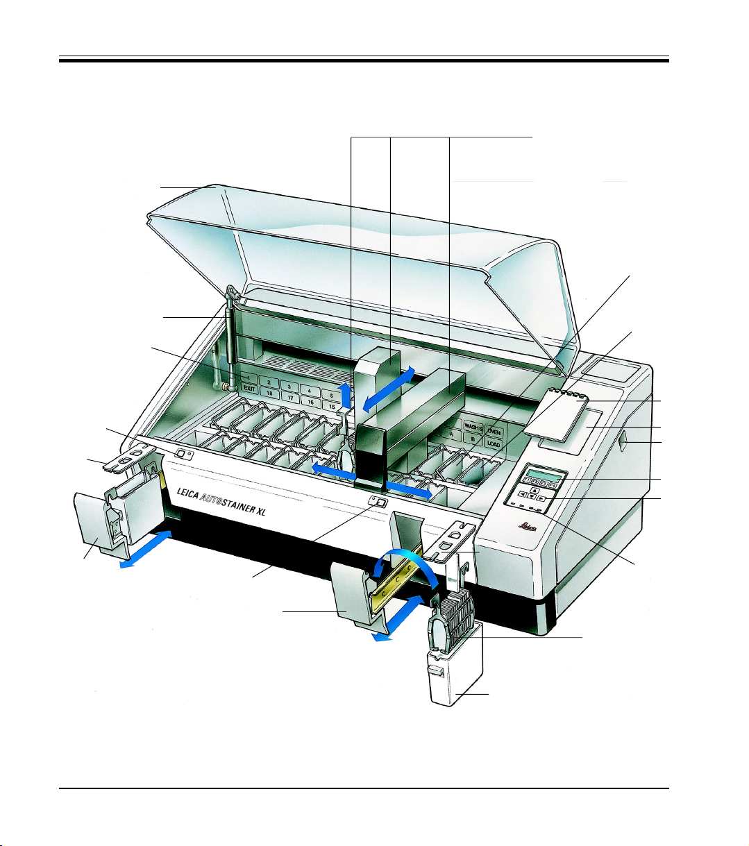
Front view
1. Transfer mechanism
2. Wash stations
3. Oven
4. Program pad
5. Program pad recess
6. ON/STOP switch
7. Display screen
8. Keypad
9. LED indicators
10. Slide rack
11. Lid
12. Reagent container
13. Load drawer
14. Load LED and key
15. Exit drawer
16. Slotted lid
17. Exit LED and key
18. Container map on fume filter cover
19. Lid support
20. Lid
24
23
3231
34
33
22
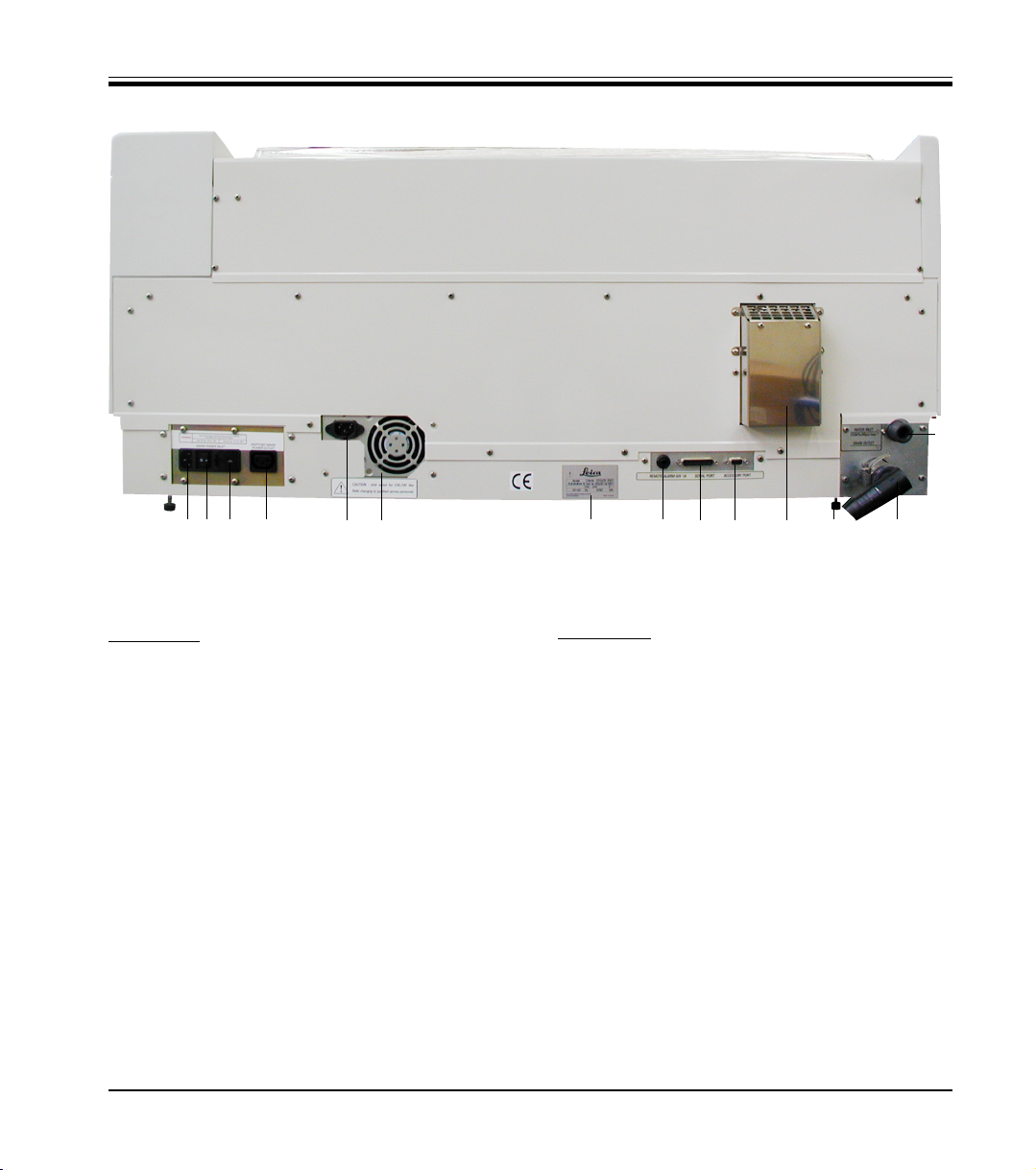
Rear panel
21. Water inlet
22. Drain outlet
23. Serial port
24. Power supply
25. Oven voltage selector
26. Mains switch (ON/OFF)
27. Mains outlet
28. Feet, adjustable
29. Power jumper cable
30. Power supply inlet
31. Rating and serial number plate
32. Remote alarm socket, 50 V 1 A max
33. Accessory port
34. Exhaust air duct
35. Power supply outlet
Leica AutoStainer XL – Automated slide stainer
11
Page 12

3. Instrument features
3.2 Standard delivery - packing list
Standard delivery:
1 Leica ST5010 basic instrument (100-120 V/50-60 Hz)
1 accessories kit (0456 35660) consisting of:
- 22 reagent vessels with lids..................................................................................................... 0475 33659
- 5 wash vessels........................................................................................................................... 0456 35268
- 5 slide racks, metal.................................................................................................................... 0456 33919
- 2 lids with slots for reagent vessels ....................................................................................... 0475 34486
- 1 jumper cable - supply system............................................................................................... 0411 34604
- 1 remote alarm connector........................................................................................................ 6844 01005
- 1 hose clamp .............................................................................................................................. 0422 31972
- 1 angular connecting nozzle for hose .................................................................................... 0475 33669
- 1 V filter 3/4 ................................................................................................................................. 0456 36101
1 activated carbon filter................................................................................................................. 0474 32273
1 filter cover ..................................................................................................................................... 0456 35240
1 drip tray for paraffin (heating) (inside the instrument)........................................................... 0456 35216
1 dye log block (attached to the instrument) .............................................................................. 0456 35459
1 water supply hose with seal ...................................................................................................... 0474 32325
1 drain hose ..................................................................................................................................... 0475 35748
1 power cable USA-C-J ................................................................................................................. 0411 13559
1 operating manual Leica AutostainerXL G/E/F/S .................................................................... 0456 25634
- 1 reference manual as appendix, English only (dye logs, etc.)
12
Instruction manual V2.1 – 10/2002
Page 13

3. Instrument features
3.3 Technical Data
Specimen slide throughput: .............................................................. at least 200 specimen slides per hour
(depending on the selected program - up to 600 slides per hour)
Loading capacity: ......................................................................................................................... 11 slide racks
Slide rack capacity:............................................................................................................. 30 specimen slides
Total number of stations:................................................................................................................................. 26
Total number of reagent stations:.................................................................................................... at least 18
Reagent container volume: ...................................................................................................................... 450 ml
Number of wash stations: ........................................................................................................................ max. 5
Oven: ..................................................................................................................................................................... 1
Oven chamber temperature:.................................................................................... ambient or 30°C to 65°C
Incubation time setting: ............................................................................... from 0 sec. up to 99 min., 59 sec
Load/unload stations:............................................................................................................................... 1 each
Permanent memory capacity:.................................................. 15 programs, up to 25 program steps each
Operating temperature range:.................................................................................................... 15 °C to 35 °C
Relative humidity:................................................................................................. max. 80 %, non-condensing
Dimensions (W x D x H): ............................................................................................. 109 cm x 67 cm x 51 cm
Weight: .......................................................................................................................................................... 65 kg
Voltages: .................................................................................................................. 110 V - 120 V, 50 Hz - 60 Hz
230 V - 240 V, 50 Hz - 60 Hz
Leica AutoStainer XL – Automated slide stainer
13
Page 14
4. Installation
4.1 Site requirements
Instructions on how to install the instrument are provided in this chapter. A
diagram and description of components is also given. Finally, the procedure
for replacement of the fume filter is outlined.
The AutoStainer XL requires a solid bench of dimensions 1.090 mm long and
670 mm deep. The instrument must be located within 3 meters of a tap and
drain.
The power requirements for the AutoStainer XL are:
8 amps: at 110 volts
4 amps: at 240 volts
The voltage selector and other internal components are set by the manufacturer to suit the country of sale.
The voltage selector setting must not be altered by the user.
4.2 Connection
4.2.1 Power
14
The AutoStainer XL requires connection to a laboratory water tap with mains
pressure fitting.
• Connect the power cord to the mains outlet ((28) page 11).
• Connect the power jumper cable to the power supply outlet ((30) page
11) and to the power supply inlet ((32) page 11).
Refer to Figure 10 on page 11.
Instruction manual V2.1 – 10/2002
Page 15
4. Installation
4.2.2 Water supply
How to switch on:
1. Connect the power cord to the mains power socket and, if applicable,
switch power ON at the mains socket.
2. Set the ON/STOP switch at the side of the unit to STOP.
3. Set the ON/OFF switch at the rear of the unit to ON.
4. Set the ON/STOP switch to ON.
The instrument will then sound 3 short beeps and the Main Menu will be
displayed.
When the instrument is not in use set the ON/STOP switch at the side to
STOP.
The ON/OFF switch at the rear of the instrument should be left ON.
The instrument must never be operated without the power
jumper cable.
The instrument must be connected to an earthed mains
power outlet socket only.
Connect the water hose to the water inlet at the rear of the unit. Screw the
other end of the hose to the cold water tap. The hose has a 3/4 inch BSP
fitting. Slowly turn the tap on fully.
Ensure that the water filter is present when fitting the water
inlet hose. Failure to do so may result in leakage of water.
Drain hose
Connect the drain hose to the drain outlet on the rear of the unit.
Leica AutoStainer XL – Automated slide stainer
15
Page 16

4. Installation
4.3 Battery backup - UPS (optional)
An uninterruptable power supply (UPS) can be used to permit staining of
slides to continue during brief mains power failures.
A small UPS can be connected using the power jumper lead, as shown in
Figure 15.
The UPS should be rated at 200 VA for 5 minutes. Heating in the oven will not
be maintained by the UPS.
The UPS must be rated for use with the local mains voltage. Your distributor
can recommend a suitable UPS.
Fig. 16
16
Instruction manual V2.1 – 10/2002
Page 17

4.4 Remote alarm (optional)
The remote alarm option is a latched relay that is voltage-isolated from the
rest of the instrument. When an alarm condition occurs (either a major failure of the instrument, or loss of mains power during a processing run whilst
a battery backup unit is fitted) the alarm circuit closes, sounding the alarm.
Ensure that the instrument is turned ON and press any key to reset the alarm.
If mains power failed during a run, it may be necessary to put the ON/STOP
switch at the side of the instrument to STOP, and then to ON again.
The remote alarm will only operate during loss of mains power if a battery
backup unit is fitted. Your distributor can provide connection details for the
remote alarm.
The remote alarm connected to the instrument must be rated at less than 1
amp and a maximum of 50 Volts.
4. Installation
A battery-powered remote alarm must be used if you require
the remote alarm to sound when the mains power fails.
Connect the remote alarm to the alarm socket at the rear of the unit, using a
6.25 mm phono jack.
4.5 Fume control system
Fumes are exhausted through the activated carbon filter which must be
changed every three months (with average usage).
To remove a filter, lift out the plate covering the filter. Refer to Figure 2. Remove the filter, using the tabs. Replace with a new filter and fit the cover into
place.
4.6 Oven
Fit the wax tray into the bottom of the oven.
Leica AutoStainer XL – Automated slide stainer
17
Page 18

5. Operation
Introduction
This chapter describes how to operate AutoStainer XL. It includes sections
on how to use the control panel functions and other indicators, how to create and edit programs and how to stain slides.
AutoStainer XL offers some unique features not available in other stainers
and these are explained in subsequent sections. Firstly, slide racks are loaded
and unloaded by means of drawer, not by opening the lid. If the instrument is
free to accept a rack for staining the Load LED will be on. After loading, the
Load key must be pressed to inform the instrument to begin processing. Simi-
larly, if a rack is finished staining in the Exit drawer the Exit LED will be on.
The Exit key must be pressed to inform the instrument when the rack is removed. Programs can finish at any station. However, if the EXIT drawer is
not the last step then the LCD will inform you of the station to unload from.
In this case, the lid will have to be opened to remove the rack.
AutoStainer XL can accept racks whenever the Load LED is on and process
up to 11 racks simultaneously.
Each rack can be processed according to any of the 15 programs, provided
that the reagents are available and the program chosen is compatible (no
conflicting sequence) with programs already being used.
18
Instruction manual V2.1 – 10/2002
Page 19

Communication
5.1 The control panel
5. Operation
Communication with AutoStainer XL is via the control panel, load and unload keys and associated indicators and audible signals.
The control panel consists of an LCD display, the keypad and four LEDs.
The display
The display is a four-line LCD with backlighting. The fourth line is usually
reserved for commands associated with the function keys [F1] to [F4]. A flash-
ing cursor appears beneath user-changeable settings.
The keypad
The membrane keypad incorporates 4 function keys and 4 arrow keys. The
function keys perform the action indicated immediately above them on the
fourth line of the display. The arrow keys move the cursor in the direction
indicated. They are also used to select digits and other settings.
Contact with solvents, use of sharp instruments or excessive
force may damage the keypad.
The LED indicators
The four LEDs are located below the arrow keys and have the following
functions. The unload LED (yellow flashing) indicates that a rack has been
completed and is ready to be removed from a station other than the exit
drawer. The staining LED (yellow) is lit when staining is in progress. The
alarm LED (red) indicates that an instrument error has occurred. The mains
LED (green) signals that mains power is available (ON at ON/OFF switch, ON
at ON/STOP switch).
Leica AutoStainer XL – Automated slide stainer
19
Page 20

5. Operation
5.2 The main menu
Load and exit keys and indicators
The load and exit keys and associated LED indicators are located adjacent
to the load and exit drawer. For further information, see Pages 32 and 33.
Audible signals
There are four types of audible signals given:
• short single beep:indicates key press;
• short double beep: indicates unacceptable key press
or error message;
• long double beep:operator attention required to remove a
completed rack;
• continuous tone: indicates unit failure.
When the AutoStainer XL is turned ON at the ON/STOP switch, the following
Main Menu will be displayed and the instrument will give 3 beeps.
20
AutoStainer XL V2.0
Main Menu
Stain Edit SetUp PC
The modes of operation of the instrument are:
• Stain: to stain slides
• Edit: to create, view or change programs
• Setup: to set, view or alter parameters such as oven temperature
and the number of dips (amount of agitation) upon entering a
reagent station
• PC: for service use only
Instruction manual V2.1 – 10/2002
Page 21

5.3 Menu map
5. Operation
Fig. 21
Leica AutoStainer XL – Automated slide stainer
21
Page 22

5. Operation
5.4 Edit a program
AutoStainer XL can store 15 programs numbered from 1 to 15 in permanent
memory. Programming is performed using a simple, menu-driven system and
all information is entered via the keypad.
A program consists of 25 steps, some of which may be blank. A step consists of the following information:
• the step number
• the station
• the immersion time
• whether the immersion time must be achieved exactly or not.
The step number defines the order in which the stations are used. The immersion time is the time the rack is fully immersed in a station.
As there is potential for timing clashes to occur when multiple racks are
present in the instrument, steps which require precise timing are designated
as ‘exact’ in the program. Immersion times at these steps are given priority
and are achieved to within ± 1 second. Racks at steps not marked as ‘exact’
will receive attention as the head becomes available.
22
Programs which are assigned to racks currently being
stained cannot be altered or copied to.
For an overview of the programming structure, refer to the menu map on
Page 21.
Instruction manual V2.1 – 10/2002
Page 23

5.4.1 Entering steps
5. Operation
1. Press [F2] Edit from the Main Menu.
2. Select the desired program number using the
3. Press [F2] Edit.
The first step of the program is then displayed under the following headings:
• step: the step number,
• stn: the station number or description,
• time: the immersion time, in minutes and seconds,
• exact: whether the immersion time is critical or not.
4. With the cursor under the step number, use the and keys to move
between step 1 to 25 of the program. Alternatively, press [F2] Next to
move to the next step.
and keys.
5. To enter program information, use the
cursor beneath the appropriate heading. Scroll through the options or
alter the digits using the
ing the
step is completed.
6. Repeat steps 4 and 5 until the program is complete.
7. To save the program, see page 24.
and keys to move to the next heading as each item in the
An immersion time of 00:00 means that this step will be omitted.
If you wish the rack to finish in the EXIT drawer, insert this
as the last step.
and keys. Fill in the program details, us-
and keys to position the
Leica AutoStainer XL – Automated slide stainer
23
Page 24

5. Operation
5.4.2 Erasing steps
Information contained in a step may be erased leaving a blank step.
1. To select the program, see steps 1 to 3, page 22,
2. To select the step to be deleted, see step 4, page 22,
3. Press [F3] Erase.
The step will be left blank.
You may enter new step details, if desired.
4. To save the program, see page 24.
5.4.3 Inserting a blank step into a program
This function is used to insert an additional step into an existing program.
1. Select the program, see steps 1 and 2, page 22.
2. Press [F2] Edit .
3. Select the step number where the new (blank) step to be inserted.
4. Press [F1] More.
5. Press [F1] More.
6. Press [F1] Insert.
7. If you wish to proceed, press [F1] Yes.
A blank step will be inserted at the step selected in (3).
24
The steps following the blank step will be renumbered. Step
25 is lost when a blank step is inserted.
8. Continue to edit the program as required.
9. To save the program, see page 24.
Instruction manual V2.1 – 10/2002
Page 25

5.4.4 Removing blank steps in a program
This function is used to remove blank steps where a program has been edited by deleting one or more steps. Steps will be sequentially renumbered in
the same sequence as the original program.
1. Select the program (see steps 1 and 2, page 22).
2. Press [F2] Edit.
3. Press [F1] More.
4. Press [F1] More.
5. Press [F3] Blank.
6. If you wish to proceed, press [F1] Yes. The blank steps will be removed
and subsequent steps will be renumbered.
7. To save the program, see page 24.
5.4.5 Saving a program
When the program is complete, to save it permanently:
1. From the Edit Program screen, press [F4] Quit. You now have the
options of saving the edited program [F1], leaving the program as it
was before the changes were made [F2], or continuing editing [F4].
2. Press [F1] to save the program, or
3. Press [F2] to leave the program unchanged, or
4. Press [F4] to continue editing the program.
5. Operation
5.4.6 Deleting a program
This function is used to delete all steps in a program.
1. Select the program (see steps 1 and 2, page 22).
2. Press [F2] Edit.
3. Press [F1] More.
4. Press [F1] More.
5. Press [F2] Delete.
6. If you wish to proceed, press [F1] Yes.
7. To save the program (which now contains no steps), see above.
Leica AutoStainer XL – Automated slide stainer
25
Page 26

5. Operation
5.4.7 Copying a program
This function is used to copy a program into another program number.
1. Select the program to be copied (see steps 1 and 2, page 22)
2. Press [F1] Copy .
If an empty program has been selected, an informative message will be given.
3. Using the
4. Press [F1] Copy.
A confirmatory message will be momentarily displayed if the copy is successful.
5. If you wish to copy the program to another program number, repeat
Steps 3 and 4.
6. Press [F4] Cancel to exit from copying.
and keys, select the program number to be copied into.
If the program number selected is not empty, an informative
message will be given.
If the program selected is assigned to a rack currently being
stained, the copy is not allowed and an informative message
will be given.
26
Instruction manual V2.1 – 10/2002
Page 27

5.4.8 Viewing a program
To view a program:
1. Select the program using steps 1 and 2, page 22.
2. Press [F3] View.
Up to four steps can be viewed simultaneously. Use the and
keys to view other steps.
3. Press [F4] to return to the previous screen.
5.4.9 Checking program compatibility
This function is used to check whether two programs can be run simultaneously. Programs cannot be run together if they need access to the same
exact station at the same time or if they contain the same two stations but in
reverse order, as in the following two programs:
Program 1 Program 2
Station 1 Station 1
Station 2 Station 3
Station 3 Station 2
5. Operation
1. Select the program (see steps 1 and 2, page 22).
2. Press [F2] Edit.
3. Press [F1] More.
4. Press [F2] Check.
5. Using the
wish to check compatibility with.
6. Press [F2] Check. - The compatibility check is performed and a subse-
quent message will inform you whether the programs are compatible.
7. If the programs are not compatible, an explanation will be given.
Press [F4] to continue.
8. Repeat Steps 5 and 6 to check compatibility with other programs.
Leica AutoStainer XL – Automated slide stainer
and keys, select the program number that you
27
Page 28

5. Operation
9. Press [F4] to return to the program selected at step 1.
Many of the program incompatibility situations arise from allocation of water wash stations. Therefore, these stations
are user-selectable.
Appendix 3 gives some examples of common staining protocols which are
compatible.
28
Instruction manual V2.1 – 10/2002
Page 29

5.5 User-adjustable parameters
There are several user adjustable parameters on the AutoStainer XL, which
apply to the instrument’s operation independently of the program selected.
These are:
. oven temperature;
. amount of agitation on entry to a station, as the number of dips;
. agitation time, specified as the time taken for a complete agitation
cycle, i.e. up and down;
. rack withdrawal time, specified as the time taken for the rack to be
withdrawn from a station;
. rack entry time, specified as the time for the rack to be lowered
into a station.
5.6 Oven
You can set the temperature of the oven in the range 30 - 65 °C, or select
heating to be OFF.
5. Operation
The oven will operate at the setting selected during the entire staining process, whether or not is being used. The selected temperature will be displayed during staining.
To set, view or change the oven setting:
1. Press [F3] SetUp from the Main Menu.
The current oven setting is then displayed on the first line.
To alter the setting:
2. Press [F1] Oven.
3. Press [F1] to turn the oven on, or
Press [F2] to turn the oven off, or
use the
4. Press [F4] to return to the SetUp screen.
The new oven setting will now be displayed.
5. Press [F4] to return to the Main Menu.
Leica AutoStainer XL – Automated slide stainer
and keys to alter the oven temperature.
29
Page 30

5. Operation
5.7 Agitation (Dips)
You can set the number of times the slide rack is moved up and down (dips)
on entry to a reagent station, in the range OFF/1-20/continuous.
If continuous is selected, only one slide rack will be processed in the instrument at any one time.
To view or change the setting:
1. Press [F3] SetUp from the Main Menu.
The current setting will be displayed on the second line.
To alter the setting:
2. Press [F2] Dips.
3. Press [F1] to turn the dips on, or
Press [F2] to turn the dips off, or
30
Use the
4. Press [F4] to return to the SetUp screen.
The new Dips setting will now be displayed.
5. Press [F4] to return to the Main Menu.
and keys to alter the number of dips.
The time for a single Dip (down and up) is selected in Rack
movement times. Use this as a guide when setting the number of dips. If the immersion time is shorter than the time to
do the set number of dips, only the number of dips that fit into
the immersion time will be done.
Instruction manual V2.1 – 10/2002
Page 31

5.8 Rack movement times
You can set the rack agitation, withdrawal and entry times to suit your run
time and agitation requirements. Refer to Appendix 1 for the allowable ranges.
To view or change the settings:
1. Press [F3] SetUp from the Main Menu.
2. Press [F3] Move.
3. To change any of the values, press [F1] Dip, [F2] Up or [F3] Down to
5. Operation
The current settings are displayed shown as the seconds taken for each
movement, i.e. agitation cycle time (Dip), rack withdrawal time (Up) and
rack entry time (Down).
position the cursor beneath the appropriate value.
5.9 Staining
4. Use the
5. Repeat steps 3 and 4 as required.
6. Press [F4] Return to return to the SetUp screen.
7. Press [F4] Return to return to the Main Menu.
This section provides a guide to staining slides.
The AutoStainer XL can accept slide racks whenever the load station is empty
and stain them according to the program selected for each rack. Different
programs may be used simultaneously provided they are compatible. To
check whether programs are compatible, refer page 26.
and keys to alter the setting.
Leica AutoStainer XL – Automated slide stainer
31
Page 32

5. Operation
5.9.1 Reagent containers
Reagent containers can be individually removed for filling. For use, fill the
reagent containers to the line marked on the inside (450 ml capacity) and
place into position in the instrument consistent with the programs you wish
to run.
There is an area for a label on the end of the containers just above the handle
pivots.
The container map inside the instrument (see Figure 11) defines the station
numbers. Ensure that the reagent containers are correctly seated and that
the handles are over to the side and will not obstruct slide rack movement.
Lids are provided to reduce evaporation while the reagent containers are
not in use.
The Load and Exit drawer containers can be filled with a reagent if desired.
However, the instrument will not control the immersion time in these stations.
5.9.2 Wash system
32
The wash system consists of five wash stations each capable of holding
one slide rack. Water enters the wash station from the base and exits from
the overflow lip at the top left hand edge.
Wash stations have a locating pin and can only be inserted
one way. Take care when fitting or removing wash stations
as the seals may be damaged by excessive force. Wet the ‘O’
ring seal before fitting a wash station.
To use the wash system, slowly turn the laboratory tap on fully. The flow
control valve in the AutoStainer XL will limit the total water flow in the wash
stations to 8 liters/minute.
If the water flow drops below this level for any reason the
wash period specified in the program may have to be extended.
Instruction manual V2.1 – 10/2002
Page 33

5.9.3 Water saving
The AutoStainer XL is fitted with a water-saving feature which stops the
flow of water when none of the wash stations is in use and the excess reagent has been flushed from them.
5.9.4 Loading slide racks
Slide racks are inserted into the instrument via the load drawer only, situated at the front right hand side of the instrument. To operate the drawer,
grasp and push up with several fingers on the release lever on the underside of the drawer and pull outwards.
To load a slide rack:
1. Select [F1] Stain from the Main Menu.
5. Operation
The instrument will take a few seconds to initialize.
If a rack is already loaded then the Abort Menu will be displayed. Press (F1) Stain to continue.
2. Select the required program number using the
Check to see that the load drawer is empty (the (Load) LED will be lit)
Open the drawer and insert the slide rack, ensuring that it is correctly
seated. Close the drawer.
3. Press the (Load) key.
If the program is compatible with programs in use then the (Load) LED
will go off and the rack will be processed according to the chosen program, otherwise an informative message will be given and the rack will
not be processed.
4. To load additional slide racks, repeat steps 2 and 3.
If the instrument is processing a rack, there may be a delay
before additional racks begin processing.
Leica AutoStainer XL – Automated slide stainer
and keys.
33
Page 34

5. Operation
5.9.5 Unloading racks from the exit drawer
When a rack is in the exit station, the (Exit) LED will be on and the beeper
will sound every 30 seconds.
To unload a rack from the exit drawer:
1. Open the exit drawer carefully and remove the rack. Alternatively, remove the entire reagent container from the drawer and replace it with
another.
2. Close the drawer and press the (Exit) key. The LED will then go off.
If the (Exit) key is not pressed the instrument will be unable
to finish the processing of further racks which require this
station.
5.9.6 Unloading racks from other stations
If the final step in a program is not the exit drawer, the (Unload) LED on the
control panel will flash when processing is complete.
34
To unload the rack:
1. Press [F1] Unload.
A confirmatory message will be given while the head completes its current operation. The station number of the completed rack will then be
displayed.
2. Select the station number of the rack you wish to remove using the
and keys (if more than one rack is completed), or
3. Press [F4] Cancel if you do not wish to unload the rack. The instrument
will then resume processing.
Instruction manual V2.1 – 10/2002
Page 35

4. Press [F1] Unload.
5. Press [F1] Done.
6. Repeat steps 2 to 5 to remove other completed racks.
5.9.7 Interrupting staining
The staining can be interrupted to:
• edit a program not currently being used for staining,
• change the general instrument SetUp parameters,
• allow access to the instrument to check/change reagents,
• abort staining of one more racks.
To interrupt staining:
1. Press [F4] Pause to return to the Abort screen.
5. Operation
Open the lid and remove the rack.
If staining is interrupted, immersion times during Pause will
not be identical to those in the chosen program(s).
If no racks are loaded then the Main Menu will be displayed.
2. To abort a rack, refer to page 35 or
3. Press [F1] Stain to continue staining, or
4. Press [F4] Main Menu to return to the Main Menu.
You may now edit programs not currently in use or change the instrument SetUp parameters.
To resume staining, press [F1] from the Main Menu.
Leica AutoStainer XL – Automated slide stainer
35
Page 36

5. Operation
5.9.8 Aborting a rack
To abort staining of a rack:
1. Press [F4] Pause from the Staining screen.
2. Press [F2] Abort rack.
3. Using the
wish to abort.
4. Press [F2] Abort.
5. Remove the rack, as instructed. Press [F1] Done.
6. To abort other racks, repeat steps 3 to 5.
7. Press [F4] Cancel to exit from the Abort screen.
8. Press [F1] to continue staining or press [F4] to return to the Main Menu
as desired.
and keys, select the station containing the rack you
36
Instruction manual V2.1 – 10/2002
Page 37

6.1 Cleaning the instrument
Clean interior stainless steel surfaces with detergent and rinse with water.
Clean the head covers by wiping with a damp cloth.
The drain system may be flushed with 5% Sodium Hypochlorite to inhibit
microbial growth. If used, ensure that this solution does not remain in contact with any metal parts for prolonged periods and flush well with water
after use. Exterior (painted) surfaces can be cleaned with a mild detergent
and wiped with a damp cloth.
Wipe the control panel carefully with a damp cloth.
6.1.1 Wash containers
6. Cleaning and Maintenance
The head contains sensitive electronic components. Do not
use liquids directly on this region. Wipe clean only.
Avoid the use of solvents on exterior surfaces and especially
on the control panel and lid.
Remove the wash containers and clean with detergent.
6.1.2 Reagent containers
Wash in warm water with detergent.
Do not wash reagent or wash containers in an automatic
dishwasher.
6.1.3 Slide racks
Clean with detergent or laboratory cleaning agent as required.
6.1.4 Oven
Periodically check the wax tray at the bottom of the oven and clean it if
excessive wax dripping has occurred.
Leica AutoStainer XL – Automated slide stainer
37
Page 38

7. Trouble shooting
Introduction
AutoStainer XL continually monitors itself and will report any errors as they
occur. If a minor error occurs during staining the instrument will attempt to
correct the problem first. If it is unsuccessful then a message will be given
and the instrument will wait for the user to rectify the problem.
Some faults cause the alarm to sound. The alarm can be turned off by pressing [F1] Quiet.
[F2] Pause can be used to pause staining from the error message display.
A list of instrument messages and their meanings follows.
38
Instruction manual V2.1 – 10/2002
Page 39

7.1 Instrument failures
7. Trouble shooting
Mains power fail
Power supply fail
Make sure that the head
is free of obstruction
Head stalled
Fume system blocked
Oven failure
Oven overheating
This warning message indicates that mains power has failed. It will only appear if
a UPS is fitted. Refer to page 15 for further information.
The power supply has failed and must be serviced.
The rack transfer arm (head) has stalled during operation. The most likely causes
of this are:
1. Reagent container not properly seated
2. Handle not properly positioned
3. Lid left on reagent container, or
4. Slide rack bent
The instrument will attempt to restart staining once the problem is rectified.
Even after attempting to restart staining the head is still unable to move freely.
Remove any obstructions and recommence staining or contact your service
agent if the problem persists.
The outlet duct at the rear of the instrument is blocked. Remove the blockage.
The oven has failed and must be serviced. The instrument is still operational at all
other stations but slide drying must be performed outside the AutoStainer
The most likely cause of this message is a blockage in the oven. Check that the
slot at the base of the oven is not obstructed.
Remove obstruction and
replace rack on hook
Leica AutoStainer XL – Automated slide stainer
The rack might have disengaged from the hook. Rectify the cause of the problem
(e.g. reagent container not properly seated) and replace rack on hook.
39
Page 40

7. Trouble shooting
7.2 Information and warnings
7.2.1 During staining
Program (x) cannot be
used for staining
Program (x) is not compatible with programs
in use
Ensure a rack is in the
Load drawer and close
the drawer
Ensure the Exit drawer
is empty and close the
drawer
Program (x) is either empty, or consists entirely of blank or zero time steps.
Program (x) is incompatible with a program assigned to a rack(s) currently being
stained. The rack(s) must be completed before program (x) can be used. Refer to
Page 26.
The load drawer must be closed before the instrument can pick up the rack.
The Exit drawer must be closed before a rack can be placed into it.
40
Instruction manual V2.1 – 10/2002
Page 41

7.2.2 During editing programs
7. Trouble shooting
Station (x) and Station
(y) are in reverse order
The steps after Exit will
be ignored
Program (x) is in use for
staining and cannot be
altered
The message occurs during a compatibility check of two programs. The stations
specified are in the opposite order in the two programs which cannot be used
concurrently.
Exit occurs before the end of the program and the remainder of the steps will be
ignored.
A program which is currently being used for staining cannot be altered. Copy the
program to another program number and then edit it.
Leica AutoStainer XL – Automated slide stainer
41
Page 42

7. Trouble shooting
7.2.3 During SetUp
SetUp lost. Default SetUp used.
Battery backed RAM
Failure! Service is required.
Caution: increasing
Dips might extend some
station times
Programs and SetUp have been lost and must be entered again.
The internal memory must be replaced. Contact your service agent.
Increasing the amount of agitation while racks are currently being stained might
extend exact immersion times. Selecting continuous agitation will result in only
one rack being progressed at a time.
42
Instruction manual V2.1 – 10/2002
Page 43

Warranty
Leica Microsystems Nussloch GmbH guarantees that the contractual product delivered has been subjected to a comprehensive quality control procedure based on the Leica in-house testing standards, and that the product is
faultless and complies with all technical specifications and/or agreed characteristics warranted.
The scope of the warranty is based on the content of the concluded agreement. The warranty terms of your Leica sales organization or the organization from which you have purchased the contractual product shall apply
exclusively.
Technical service information
If you require technical service or replacement parts, please contact your
Leica sales representative or dealer who sold the product.
Please provide the following information:
• Model name and serial number of the instrument.
• Location of the instrument and name of the person to contact.
• Reason for the service call.
• Date of delivery.
8. Warranty and service
Decommissioning and disposal
The instrument or parts of the instrument must be disposed of in compliance
with the local laws.
Leica AutoStainer XL – Automated slide stainer
43
Page 44

APPENDIX 1
User-adjustable parameters
Item Factory setting Changeable Range
Slide per rack N/A N/A 0-30
Racks in the instrument N/A Y 0-11
Stations 18 reagent N 0-18
5 wash 0-5
1 oven 0-1
1 load drawer 1
1 exit drawer 0-1
Programs 15 N 15
Steps per program 25 N 25
(Note: some steps
can be blank)
Immersion time N/A Y 0 sec - 59 min 99 sec
(Note: 0 seconds means the
step is omitted)
Timing accuracy (‘Exact’) N/A Y ± 1 second (‘Exact’)
-0, +infinity (not ‘Exact’)
Oven temperature N/A Y Off/30 - 65 °C
Agitation (Dips) N/A Y Off/1-20/ Continuous
Agitation time (Dip)
(seconds/cycle) 2 Y 1-4
Rack withdrawal
time (Up) (seconds) 9 Y 4-9
Rack entry time (Down)
(seconds) 2 Y 2-4
44
Instruction manual V2.1 – 10/2002
Page 45

Consumables and accessories
Consumables
Activated carbon filter
Accessories
Slide rack adapter Sakura
Slide rack adapter Medite / Meisei 20
Slide rack adapter Medite / Meisei 30
Slide rack adapter, Shandon
Frame for individual large slides
Blocking plug for wash station
O ring hook
O ring for wash container
Drain hose
Chimney adapter
Inlet hose
Reagent container handle
Wash containers
Slide rack 30 - 1 unit
Plastic slide rack 30 - 1 unit
Output rack
Reagent container holder
Lid for reagent containers inside the instrument
Slotted lid for reagent container
Program pad
Instruction manual
APPENDIX 2
Leica AutoStainer XL – Automated slide stainer
45
Page 46

APPENDIX 3
Compatible staining programs
Program 1H&E Program 2 Papanicoleau
Reagent Station Step Time Exact Step Time Exact
Oven 1 10:00 Y
Xylene 1 2 2:00 N
Xylene 2 3 2:00 N
100% Alcohol 3 4 2:00 N
100% Alcohol 4 5 2:00 N
70% Alcohol 5 6 1:00 N 1 1:30 N
Wash Wash 1 7 2:00 N 2 2:00 N
Hematoxylin 6 8 5:00 Y 3 3:30 Y
Wash Wash 2 9 2:00 N 4 2:00 N
Acid Alcohol 7 10 0:02 Y 5 0:05 Y
Wash Wash 3 11 3:00 N 6 2:00 N
Scott’s 8 12 3:00 Y 7 4:00 Y
Wash Wash 4 13 3:00 N 8 2:00 N
95% Alcohol 9 9 1:30 N
OG 6 10 10 2:00 Y
95% Alcohol 11 11 1:30 N
95% Alcohol 12 12 1:30 N
EA 50 13 13 2:30 Y
Eosin 14 14 2:00 Y
95% Alcohol 15 15 0:30 y 14 1:30 Y
100% Alcohol 16 16 2:00 N 15 1:30 Y
100% Alcohol 17 17 2:00 N 16 1:30 Y
100% Alcohol 18 18 2:00 N 17 1:30 y
Xylene Exit 19 18
46
Washes 1 to 4 (and the stations between) are used in the same sequence in both programs. - These programs are compatible with each other but not with programs on
page 47.
Instruction manual V2.1 – 10/2002
Page 47

APPENDIX 3
Compatible staining programs
Program 1H&E Program 5 Hx
Counterstain
Reagent Station Step Time Exact Step Time Exact
Oven 1 10:00 Y
Xylene 1 2 2:00 N
Xylene 2 3 2:00 N
100% Alkohol 3 4 2:00 N
100% Alkohol 4 5 2:00 N
70% Alcohol 5 6 1:00 N
Wash Wash 1 7 2:00 N
Hematoxylin 6 8 5:00 Y 1 5:00 Y
Wash Wash 2 9 2:00 N 2 2:00 N
Acid-Alcohol 7 10 0:02 Y 3 0:02 Y
Wash Wash 3 11 3:00 N 4 3:00 N
Scott’s 8 12 3:00 Y 5 3:00 Y
Wash Wash 4 13 3:00 N 6 3:00 N
Eosin 14 14 2:00 Y
95% Alcohol 15 15 0:30 Y
100% Alkohol 16 16 2:00 N 7 2:00 N
100% Alkohol 17 17 2:00 N 8 2:00 N
100% Alkohol 18 18 2:00 N 9 2:00 N
Xylene Exit 19 10
Leica AutoStainer XL – Automated slide stainer
47
Page 48

Glossary
CARRYOVER
CURSOR
DIP/DIPS/DIPPING
DISENGAGE
ENGAGE
EXACT
IMMERSION
EXIT DRAWER
FUME
EXTRACTION
The amount of REAGENT carried from one STATION to another by the SLIDE
RACK.
Flashing bar on LCD beneath user-changeable data.
The SLIDE RACK is moved up and down a programmable number of times on
entry to a STATION.
The process by which the HEAD detaches itself from the SLIDE RACK after
PUTDOWN or DIPPING.
The process by which the HEAD attaches itself to the SLIDE RACK prior to
PICKUP.
The IMMERSION time is achieved within 1 second.
Drawer into which SLIDE RACKS are placed by the instrument for subsequent collection by the user.
A fan draws fumes through a filter which removes dangerous SOLVENT vapors.
HEAD (TRANSFER
ARM)
IMMERSION TIME
LCD
LEDs
48
XYZ device used to PICKUP, PUTDOWN, ENGAGE, DISENGAGE, DIP and
move SLIDE RACKS from STATION to STATION.
The time a SLIDE RACK spends in a STATION. Timed from end of PUTDOWN
to start of PICKUP.
The Liquid Crystal Display situated on the control panel.
Light Emitting Diodes situated on the control panel and near LOAD and EXIT
DRAWERS.
Instruction manual V 2.1 – 10/2002
Page 49

Glossary
LOAD DRAWER
NON-EXACT IMMERSION
OVEN
PC
PICKUP
PROGRAM
PUTDOWN
REAGENT
REAGENT STATION
SETUP
SLIDE
SLIDE RACK
SOLVENT
STAINING
Drawer into which SLIDE RACKS are placed by the user and from which
they are taken by the instrument for STAINING.
The IMMERSION TIME is achieved within –0, + infinity seconds, i.e. it specifies a minimum time period only.
STATION through which warm air is blown in order to dry SLIDES and adhere tissue sections to them.
Personal computer based on the original IBM architecture.
The SLIDE RACK is withdrawn from a STATION by the HEAD in such a way
as to minimize CARRYOVER.
Series of STEPS by which a SLIDE RACK undergoes STAINING in the instrument.
The SLIDE RACK is placed in a STATION by the HEAD.
Chemical used for STAINING.
Container holding REAGENT into which SLIDE RACKS are placed by the instrument.
Parameters which apply to the operation of the instrument independently of
the program used, i.e. OVEN temperature and DIPS setting.
Glass microscope slide 25 mm x 75 mm x 1 mm.
Holds SLIDES to ease handling by the instrument.
Organic liquid e.g. Xylene, Ethanol.
The process by which tissue sections are stained.
Leica AutoStainer XL – Automated slide stainer
49
Page 50

Glossary
STATION
STEP
TRANSFER ARM
UNLOAD
UPS (BATTERY
BACKUP)
WASH STATION
Location in the instrument where part of a STAINING sequence takes place.
Defined by the STATION, IMMERSION TIME and timing accuracy for one
discrete event in the STAINING sequence.
See HEAD.
The user removes a SLIDE RACK from the EXIT DRAWER or from the station
in which it completes its programmed sequence.
Uninterruptable power supply which allows STAINING to continue during
brief mains power failures.
Container through which water flows to wash REAGENT from a SLIDE RACK
and the SLIDES in it.
50
Instruction manual V 2.1 – 10/2002
 Loading...