

Page 1
SUB-MICRO SERIES DYNAMIC BRAKING OPTION (FOR MODELS RATED 0.25 - 10 HP)
INST ALLATION AND OPERATION INSTRUCTIONS
Manual Number: SDBR06C
The Sub-Micro Series Dynamic Braking option can be used with all SM, SM-Plus and SM-Basic models.
!
WARNING!
Remove power from the drive and wait three minutes before wiring the DB module. Incorrect wiring of the B+ and B- terminals will result in
equipment damage! The B+ terminal on the DB module must be connected to the B+ terminal on the Sub Micro drive, and the B- terminal on the DB
module must be connected to the B- terminal on the Sub-Micro drive.
DO NOT make connections to R+ and R- without consulting LEESON. Damage to the Dynamic Braking module and/or drive may result.
SM-PLUS SERIES DRIVES
PROGRAMMING
1. Set Parameter 09 (TB-31 OUTPUT) to DYNAMIC BRAKING (04).
2. Set Parameter 10 (TB-13A FUNCTION) to DB FAULT (09), or set Parameter 12
(TB-13C FUNCTION) to DB FAULT (08).
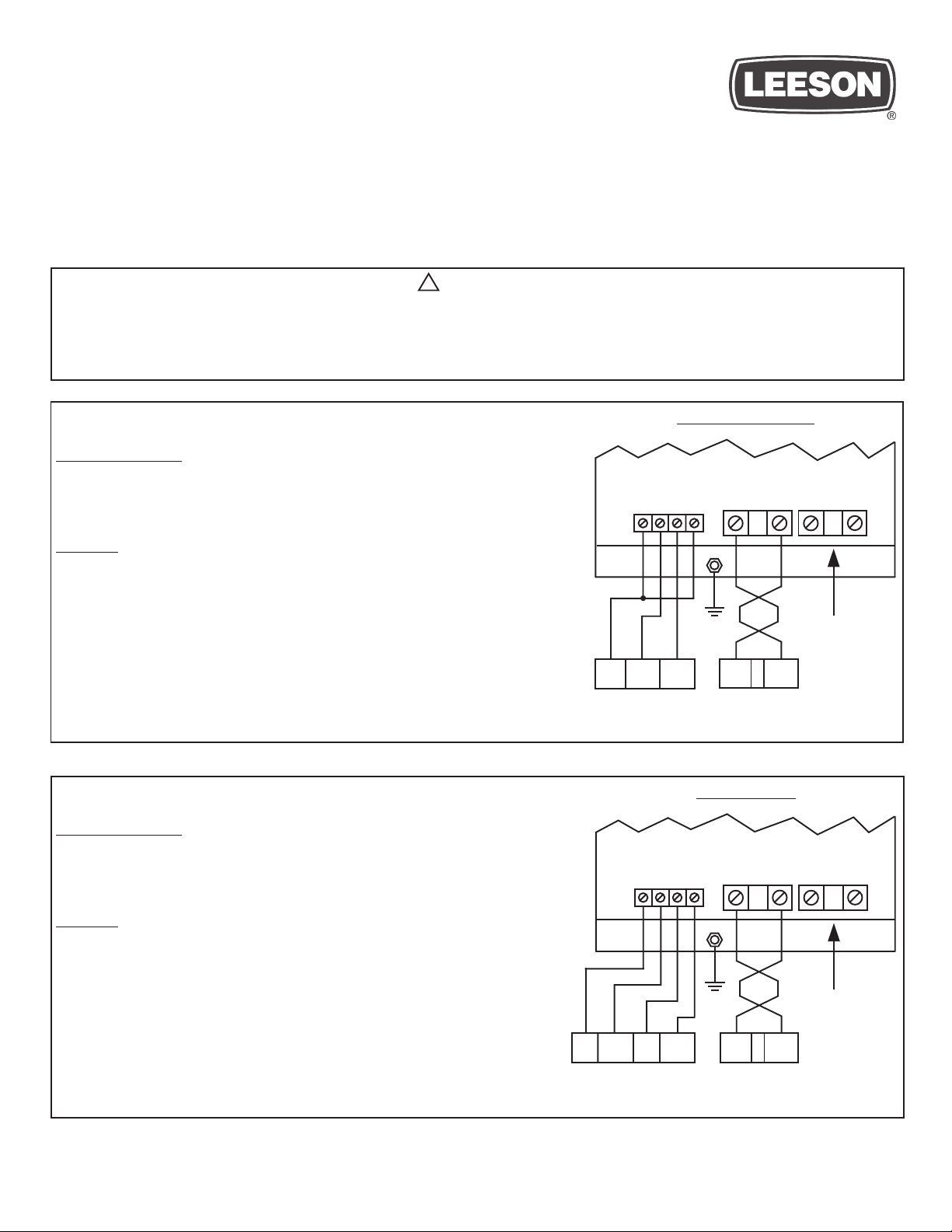
WIRING
The diagram to the right illustrates how the DB module is wired to the SM-PLUS Series
drive. In this diagram, TB-13A is used as the DB FAULT input, but TB-13C could be
used instead if TB-13A is required for another function.
NOTE 1: Use 18 AWG wire for control connections.
NOTE 2: Use minimum 14 AWG wire for connections to B+ and B-. The B+ and B-
wires MUST be twisted together and must be less than 12 inches long.
NOTE 3: DO NOT make connections to R+ and R- without consulting LEESON.
Damage to the Dynamic Braking module and/or drive may result.
SM SERIES DRIVES
PROGRAMMING
1. Set Parameter 12 (TB-13E FUNCTION) to DYNAMIC BRAKING (20).
2. Set Parameter 10 (TB-13A FUNCTION) to INVERSE EXT. FAULT (09), or set
Parameter 11 (TB-13B FUNCTION) to INVERSE EXT. FAULT (10).
DB OPTION MODULE
42
13A231
SM-PLUS
CONTROL
TERMINALS
DB OPTION MODULE
42
SM-PLUS DIAGRAM
B - B + R + R -
464743
GND
(SEE NOTE 3)
B - B +
SM-PLUS
POWER
TERMINALS
SM DIAGRAM
B - B + R + R -
464743
WIRING
The diagram to the right illustrates how the DB module is wired to the SM Series drive.
In this diagram, TB-13A is programmed for INVERSE EXTERNAL FAULT, but TB13B could be used instead if TB-13A is required for another function.
NOTE 1: Use 18 AWG wire for control connections.
NOTE 2: Use minimum 14 AWG wire for connections to B+ and B-. The B+ and B-
wires MUST be twisted together and must be less than 12 inches long.
NOTE 3: DO NOT make connections to R+ and R- without consulting LEESON.
Damage to the Dynamic Braking module and/or drive may result.
LEESON ElectricLEESON Electric
LEESON Electric • 2100 Washington St. • Grafton, WI 53024 • Ph: (262) 377-8810 • Fax: (262) 377-9025 • www.leeson.com
LEESON ElectricLEESON Electric
2
SM
CONTROL
TERMINALS
GND
(SEE NOTE 3)
13A13E 11
B - B +
SM
POWER
TERMINALS
Page 2
SM-BASIC SERIES DRIVES
PROGRAMMING
1. Set Parameter 06 (TB-14 OUTPUT) to DB BRAKE (11).
2. Set Parameter 10 (TB-13A FUNCTION) to DB FAULT (08), or set Parameter 11
(TB-13B FUNCTION) to DB FAULT (08), or set Parameter 12 (TB-13C
FUNCTION) to DB FAULT (07).
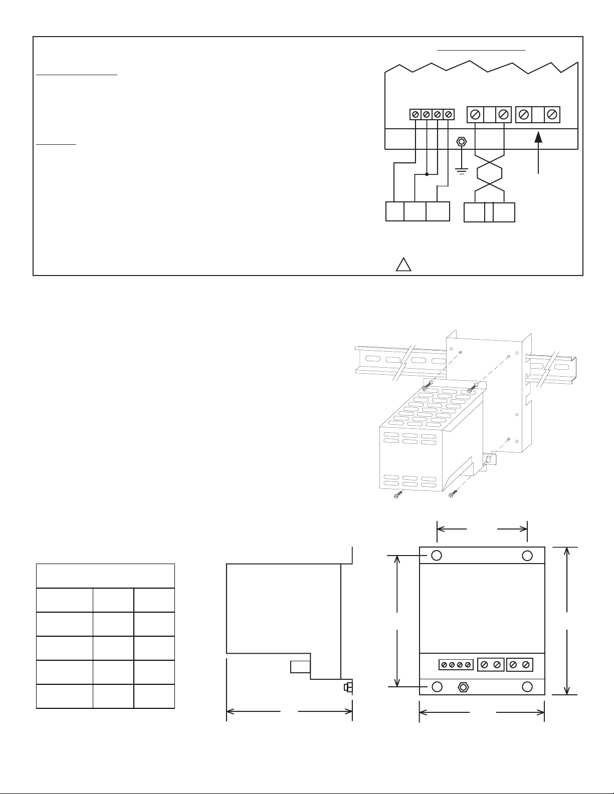
WIRING
The diagram to the right illustrates how the DB module is wired to the SM-Basic drive.
In this diagram, TB-13A is used as the DB FAULT input, but TB-13B or TB-13C could
be used instead if TB-13A is required for another function.
NOTE 1: Use 18 AWG wire for control connections.
NOTE 2: Use minimum 14 AWG wire for connections to B+ and B-. The B+ and B-
wires MUST be twisted together and must be less than 12 inches long.
NOTE 3: DO NOT make connections to R+ and R- without consulting LEESON.
Damage to the Dynamic Braking module and/or drive may result.
SM-Basic DIAGRAM
DB OPTION MODULE
42
13A14 11
SM-BASIC CONTROL
TERMINALS
WARNING! SM-Basic control terminals
!
are hot to ground! Do not touch!
B -
464743
GND
B - B +
SM-BASIC POWER
TERMINALS
R + R -
B +
(SEE NOTE 3)
MOUNTING THE DYNAMIC BRAKING MODULE
The diagram below illustrates how to mount the DB Module. The DB
Module is compatible with the DIN Rail Mounting Kit option, or can
simply be mounted to a flat surface such as an electrical panel.
The DB module is a heat producing device; DO NOT mount the DB
module below the Sub-Micro Series drive! The DB module must be
mounted above or to the side of the Sub-Micro Series drive.
DIMENSIONS (inches)
HP W D
SIDE VIEW
0.25 - 1.5 3.1 3.1
DB MODULE
4.06"
DIN RAIL
BRACKET
2.00"
FRONT VIEW
4.6"
2 - 3 3.1 4.3
53.15.6
7.5 - 10 4.2 6.7
GND
D
LEESON ElectricLEESON Electric
LEESON Electric • 2100 Washington St. • Grafton, WI 53024 • Ph: (262) 377-8810 • Fax: (262) 377-9025 • www.leeson.com
LEESON ElectricLEESON Electric
W
 Loading...