

Leeson SPEEDMASTER SM2 Series, SPEEDMASTER SM4 Series Installation And Operation Manual
SPEEDMASTER
®
SM2 Series Flux Vector
SM4 Series Flux Vector
Installation and
Operation Manual
A Regal Brand
CALL NOW 800-985-6929
http://www.automatedpt.com
Email: charles@automatedpt.com
CALL NOW 800-985-6929
http://www.automatedpt.com
Email: charles@automatedpt.com

1
1 Safety information ...................................................................................3
2 Technical data ..........................................................................................5
2.1 Standards and application conditions ...................................................................................... 5
2.2 Ratings ................................................................................................................................... 6
3 Installation ................................................................................................8
3.1 Dimensions and mounting ...................................................................................................... 8
3.1.1 NEMA 1 (IP31) Models ................................................................................................... 8
3.1.3 NEMA 4X (IP65) Models ................................................................................................. 9
3.2 Electrical installation ............................................................................................................. 10
3.2.1 Power Connections ...................................................................................................... 10
3.2.1.1 Mains Connection to 120VAX Single-Phase Supply ....................................... 10
3.2.1.2 Mains Connection to 240VAC Single-Phase Supply ....................................... 11
3.2.1.3 Mains Connection to Three-Phase Supply ..................................................... 11
3.2.1.4 Motor Connection ......................................................................................... 11
3.2.1.5 Installation Recommendations for EMC Compliance ..................................... 12
3.2.1.6 NEMA 4X (IP65) Input Terminal Block ............................................................12
3.2.1.7 Dynamic Brake Connections .........................................................................13
3.2.2 Fuses/cable cross-sections ..........................................................................................14
3.2.3 Control terminals .......................................................................................................15
4 Commissioning ......................................................................................16
4.1 Local Keypad & Display ........................................................................................................16
4.2 Drive Displays and Modes of Operation ................................................................................. 19
4.3 Parameter setting ................................................................................................................. 20
4.4 Electronic programming module (EPM) .................................................................................20
4.5 Parameter menu ................................................................................................................... 21
4.5.1 Basic Setup Parameters .............................................................................................. 21
4.5.2 I/O Setup Parameters .................................................................................................. 25
4.5.3 Advanced Setup Parameters .......................................................................................32
4.5.4 PID Parameters ........................................................................................................... 37
4.5.5 Vector Parameters ...................................................................................................... 40
4.5.6 Network Parameters ................................................................................................... 43
4.5.7 Diagnostic Parameters ................................................................................................ 44
4.5.7.1 Terminal & Protection Status Display ............................................................ 46
4.5.7.2 Keypad Status Display .................................................................................. 46
4.5.8 Onboard Communications Parameters 15-25 HP ........................................................47
4.5.9 Sequencer Parameters ...............................................................................................48
4.5.9.1 Sequencer Flow Diagram Left ...................................................................... 57
4.5.9.2 Sequencer Flow Diagram Right .................................................................... 58
4.5.9.3 Sequencer Status ......................................................................................... 59
5 Troubleshooting and Diagnostics ........................................................60
5.1 Status/Warning Messages ....................................................................................................60
5.2 Drive Configuration Messages .............................................................................................. 62
5.3 Fault Messages ......................................................................................................................6
Appendix A ................................................................................................66
A.1 Permissable Cable Lengths ................................................................................................... 66
Contents
CALL NOW 800-985-6929
http://www.automatedpt.com
Email: charles@automatedpt.com
CALL NOW 800-985-6929
http://www.automatedpt.com
Email: charles@automatedpt.com
This documentation applies to the SM2 and SM4 Vector frequency inverter, and contains important
technical data and describes installation, operation, and commissioning.
These instructions are only valid for SM2 and SM4 Vector frequency inverters with software rev 20
(see drive nameplate).
Please read the instructions before commissioning.
CA BD
Type:
174621.00
Id-No: 00000000
INPUT:
3~ (3/PE)
400/480 V
2.9/2.5 A
50-60 HZ
OUTPUT:
3~ (3/PE)
0 - 400/460 V
2.4/2.1 A
0.75 KW/1HP
0 - 500 HZ
For detailed information
refer to instruction
Manual: SV06
Made in USA
Inverter
SM2 Vector
V0115
2
About these instructions
A
Certications
C
Input Ratings
B
Type
D
Output Ratings
Scope of delivery Important
• 1 SM2 or SM4 Vector inverter
with EPM installed
(see Section 4.4)
• 1 Operating Instructions
After receipt of the delivery, check immediately whether the
items delivered match the accompanying papers. LEESON does
not accept any liability for deciencies claimed subsequently.
Claim
• visible transport damage immediately to the forwarder.
• visible deciencies / incompleteness immediately to your
LEESON representative.
CALL NOW 800-985-6929
http://www.automatedpt.com
Email: charles@automatedpt.com
CALL NOW 800-985-6929
http://www.automatedpt.com
Email: charles@automatedpt.com

All safety information given in these Operating Instructions have the same layout:
Signal Word! (characterizes the severity of the danger)
Note (describes the danger and informs on how to proceed)
Icon
Signal Words
Warning of
hazardous
electrical voltage
DANGER!
Warns of imminent / impending danger.
Consequences if disregarded:
will result in Death or severe injuries.
Warning of a
general danger
WARNING!
Warns of potential, very hazardous situations.
Consequences if disregarded:
could result in Death or serious injuries.
Warning of damage
to equipment
STOP!
Warns of potential damage to material and
equipment.
Consequences if disregarded:
Damage to the controller/drive or its
environment.
Information
Note
Designates a general, useful note.
If you observe it, handling the controller/drive
system is made easier.
Note for UL approved system with integrated controllers: UL warnings are notes which
apply to UL systems. The documentation contains special information about UL.
Warnings!
• Suitable for use on a circuit capable of delivering not more than 200,000 rms
symmetrical amperes, at the maximum voltage rating marked on the drive.
• Use minimum 75 °C copper wire only.
• Shall be installed in a pollution degree 2 macro-environment.
Operation
Systems including controllers must be equipped with additional monitoring and protection devices
according to the corresponding standards (e.g., technical equipment, regulations for prevention of
accidents, etc.). The controller may be adapted to your application as described in this documentation.
DANGER!
• After the controller has been disconnected from the supply voltage, live components
and power connection must not be touched immediately, since capacitors could be
charged. Please observe the corresponding notes on the controller.
• Please close all protective covers and doors prior to and during operation.
• Do not cycle input power to the controller more than once every two minutes.
3
Safety information
CALL NOW 800-985-6929
http://www.automatedpt.com
Email: charles@automatedpt.com
CALL NOW 800-985-6929
http://www.automatedpt.com
Email: charles@automatedpt.com
1 Safety information
General
DANGER!
Some parts of LEESON controllers can be electrically live and some surfaces
can be hot.
Non-authorized removal of the required cover, inappropriate use, and incorrect installation or
operation creates the risk of serious injury to personnel or damage to equipment.
All operations concerning transport, installation, and commissioning as well as maintenance must be
carried out by qualied, skilled personnel who are familiar with the installation, assembly, commissioning,
and operation of variable frequency drives and the application for which it is being used.
Installation
Ensure proper handling and avoid excessive mechanical stress. Do not bend any components and
do not change any insulation distances during transport, handling, installation or maintenance.
Do not touch any electronic components or contacts. This drive contains electrostatically sensitive
components, which can easily be damaged by inappropriate handling. Static control precautions
must be adhered to during installation, testing, service and repair of this drive and associated
options. Component damage may result if proper procedures are not followed.
This drive has been tested by Underwriters Laboratory (UL) and is an approved component in
compliance with UL508 Safety Standard.
This drive must be installed and congured in accordance with both national and international
standards. Local codes and regulations take precedence over recommendations provided in this
and other LEESON documentation.
The SM2 and SM4 Vector drive is considered a component for integration into a machine or process.
It is neither a machine nor a device ready for use in accordance with European directives (reference
machinery directive and electromagnetic compatibility directive). It is the responsibility of the end
user to ensure that the machine meets the applicable standards.
Electrical connection
WARNING!
When working on live drive controllers, applicable national safety regulations must
be observed.
The electrical installation must be carried out according to the appropriate regulations (e.g.
cable cross-sections, fuses, protective earth [PE] connection). While this document makes
recommendations in regard to these items, national and local codes must be adhered to.
The documentation contains information about installation in compliance with EMC (shielding,
grounding, lters and cables). These notes must also be observed for CE-marked controllers.
The manufacturer of the system or machine is responsible for compliance with the required limit
values demanded by EMC legislation.
Application
WARNING!
The drive must not be used as a safety device for machines where there is a
risk of personal injury or material damage. Emergency Stops, over-speed
protection, acceleration and deceleration limits, etc. must be made by other
devices to ensure operation under all conditions.
The drive features many protection devices which are aimed at protecting the drive and the driven
equipment by generating a fault and shutting the drive and motor down by removing power. Mains
power variances can also result in shutdown of the drive. When the fault condition disappears or is
cleared, the drive can be congured to automatically restart. It is the responsibility of the user and/
or OEM and/or integrator to ensure that the drive is congured for safe operation.
4
Safety information
CALL NOW 800-985-6929
http://www.automatedpt.com
Email: charles@automatedpt.com
CALL NOW 800-985-6929
http://www.automatedpt.com
Email: charles@automatedpt.com
5
Technical data
2 Technical data
2.1 Standards and application conditions
Conformity
CE Low Voltage Directive (73/23/EEC)
Approvals
UL 508C Underwriters Laboratories - Power Conversion Equipment
Input voltage phase imbalance
< 2%
Supported Power Systems
TT
TN
– For central grounded systems, operation is
permitted without restrictions.
– For corner grounded 400/500V systems, operation
is possible but reinforced insulation to control
circuits is compromised.
Humidity
< 95% non-condensing
Temperature range
Transport -25 … +70°C
Storage -20 … +70°C
Operation
-10 … +55°C
(with 2.5%/°C current derating
above +40°C)
Installation height
0 … 4000m a.m.s.l.
(with 5%/1000 m current derating above 1000m a.m.s.l.)
Vibration resistance
acceleration resistant up to 1.0g
WARNING!
Earth leakage current
> 3.5 mA to PE
Max Permissable Cable Length
(1)
<=4.0 Hp (3.0 kW) 30 meters shielded, 60 meters un-shielded
=> 5.0 Hp (3.7 kW) 50 meters shielded, 100 meters un-shielded
Enclosure
IP31 / NEMA 1 IP65/NEMA 4X
NEMA 1 and NEMA 4X model enclosures are plenun rated in accordance
with UL 508C and are suitable for installation in a compartment handling
conditioned air.
Protection measures against
short circuit, earth fault, phase loss, over voltage, under voltage, motor
stalling, over temperature, motor overload
Compliance with EN 61000-3-2
Requirements
(2)
< 0.5 kW with mains choke
0.5 ... 1 kW with active lter
> 1 kW without additional measures
Compliance with EN 61000-3-12
Requirements (2)
16 ... 75 amp
Additional measures required for compliance with
EN 61000-3-12
Operation in public supply networks (Limitation of harmonic currents i.a.w. EN 61000-3-2, Electromagnetic
Compatibiliy (EMC) Limits). Limits for harmonic current emissions (equipment input current up to 16A/phase).
(1) The stated cable lengths are permissiable at default carrier frequencies (refer to parameter P166).
(2) The additional measures described only ensure that the controller meets the requirements of the EN 61000-3-2.
The machine/system manufacturer is responsible for the machine’s compliance with the regulations.
CALL NOW 800-985-6929
http://www.automatedpt.com
Email: charles@automatedpt.com
CALL NOW 800-985-6929
http://www.automatedpt.com
Email: charles@automatedpt.com
6
Technical data
2.2 Ratings
120VAC Doubler / 240VAC Models
Type
Power
[Hp/kW]
Mains Output Current
SM2
Watts
Loss
SM4
Watt
Loss
Voltage
(1)
I
in
(120V) Iin (240V) I
n
CLim
max
(2)
174603 0.33 / 0.25
120 V Single-phase (1/N/PE)
(90 … 132 V)
OR
240 V Single-phase (2/PE)
(170 … 264 V)
6.8 3.4 1.7 200 24
174604-
174652
0.5 / 0.37 9.2 4.6 2.4 200 32 32
174605-
174653
1 / 0.75 16.6 8.3 4.2 200 52 41
174651-
174654
1.5 / 1.1 20.0 10.0 6.0 200 74 74
240VAC Models
Type
Power
[Hp/kW]
Mains Output Current
SM2
Watts
Loss
SM4
Watts
Loss
Voltage
(1)
I
in
1~ (2/PE) Iin 3~ (3/PE) I
n
CLim
max
(2)
174606 0.33 / 0.25
240 V Single Phase (2/PE)
3.4 - 1.7 200 20
174607-174655 0.5 / 0.37
240 V Single-phase (2/PE)
OR
240 V Three-phase (3/PE)
(170 … 264 V)
5.1 2.9 2.4 200 27 30
174608-174656 1 / 0.75 8.8 5.0 4.2 200 41 42
174609-174657 1.5 / 1.1 12.0 6.9 6.0 200 64 63
174610-174658 2 / 1.5 13.3 8.1 7.0 200 75 73
174611-174659 3 / 2.2 17.1 10.8 9.6 200 103 97
174612 1.5 / 1.1
240 V Three-phase (3/PE)
(170 V … 264 V)
- 6.9 6.0 200 64 59
174613 2 / 1.5 - 8.1 7.0 200 75 69
174614 3 / 2.2 - 10.8 9.6 200 103 93
174615-174660 5 / 4.0 - 18.6 16.5 200 154 139
174616-174661 7.5 / 5.5 - 26 23 200 225 167
174617-174662 10 / 7.5 - 33 29 200 274 242
174618 15 / 11 - 48 42 180 485 468
174619 20 / 15 - 59 54 180 614 591
(1) Frequency Range: 48 Hz … 62 Hz
(2) Current Limit (CLim) is a percentage of the output current, In. CLim
max
is the maximum setting for P171.
CALL NOW 800-985-6929
http://www.automatedpt.com
Email: charles@automatedpt.com
CALL NOW 800-985-6929
http://www.automatedpt.com
Email: charles@automatedpt.com
7
Technical data
480VAC Models
Type
Power
[Hp/kW]
Mains Output Current
SM2
Watts
Loss
SM4
Watts
Loss
Voltage
(1)
I
in
I
n
CLim
max
(2)
400V 480V 400V 480V 400V 480V
174620-174671 0.5 / 0.37
400 V Three-phase (3/PE)
(340 … 440 V)
OR
480 V Three-phase (3/PE)
(340 … 528 V)
1.7 1.5 1.3 1.1 175 200 23 21
174621-174672 1 / 0.75 2.9 2.5 2.4 2.1 175 200 37 33
174622-174673 1.5 / 1.1 4.2 3.6 3.5 3.0 175 200 48 42
174623-174674 2 / 1.5 4.7 4.1 4.0 3.5 175 200 57 50
174624-174675 3 / 2.2 6.1 5.4 5.5 4.8 175 200 87 78
174625-174676 5 / 4.0 10.6 9.3 9.4 8.2 175 200 128 103
174626-174677 7.5 / 5.5 14.2 12.4 12.6 11.0 175 200 178 157
174627-174678 10 / 7.5 18.1 15.8 16.1 14.0 175 200 208 190
174628 15 / 11 27 24 24 21 155 180 418
174629 20 / 15 35 31 31 27 155 180 493
174630 25 / 18.5 44 38 39 34 155 180 645
174991 30 / 22 52 45 46 40 155 180 709
174992 40 / 30 68 59 60 52 155 180 1020
174710 50 / 37.5 85 74 75 65 155 180 1275
174711 60 / 45 100 87 88 77 155 180 1530
600 VAC Models
Type
Power
[Hp/kW]
Mains Output Current
SM2
Watts
Loss
SM4
Watts
Loss
Voltage
(1)
I
in
I
n
CLim
max
(2)
174631-174663 1 / 0.75
600 V Three-phase (3/PE)
(425 … 660 V)
2.0 1.7 200
37 31
174632-174664 2 / 1.5 3.2 2.7 200 51 43
174633-174665 3 / 2.2 4.4 3.9 200 68 57
174634-174666 5 / 4.0 6.8 6.1 200 101 67
174635-174667 7.5 / 5.5 10.2 9 200 148 116
174636-174668 10 / 7.5 12.4 11 200 172 152
174637 15 / 11 19.7 17 180 380
174638 20 / 15 25 22 180 463
174639 25 / 18.5 31 27 180 560
174993 30 / 22 36 32 180 640
174994 40 / 30 47 41 180 930
174712 50 / 37.5 59 52 180 1163
174713 60 / 45 71 62 180 1395
(1) Frequency Range: 48 Hz … 62 Hz
(2) Current Limit (CLim) is a percentage of the output current, In. CLim
max
is the maximum setting for P171.
For 480VAC models, the CLim
max
value in the 480V column of the table is used when P107 is set to 1.
The CLim
max
value in the 400V column is used when P107 is set to 0.
STOP!
Drive Derating
The SM2 and SM4 Vector Series drive is designed to operate at the Nominal Output Current (In)shown
in the Ratings tables for most standard applications and industrial environments. The drive output
current or operating temperature may need to be limited as described below:
• For installations above 1000m a.m.s.l., derate I
n
by 5% per 1000m, do not exceed 4000m a.m.s.l.
• Operation above 40°C, derate In by 2.5% per °C, do not exceed 55°C.
• Carrier Frequency (P166):
- If P166=2 (8 kHz), derate I
n
to 92% of drive rating or do not exceed 33°C ambient
- If P166=3 (10 kHz), derate In to 84% of drive rating or do not exceed 27°C ambient
For combinations of the above, please consult LEESON applications support for proper derating.
CALL NOW 800-985-6929
http://www.automatedpt.com
Email: charles@automatedpt.com
CALL NOW 800-985-6929
http://www.automatedpt.com
Email: charles@automatedpt.com
Drives must not be installed where subjected to adverse environmental conditions
such as: combustible, oily, or hazardous vapors or dust; excessive moisture; excessive
vibration or excessive temperatures. Contact LEESON for more information.
8
Installation
3 Installation
3.1 Dimensions and mounting
3.1.1 NEMA 1 (IP31)
b1
a1
a
b
c
b2
mm (in)
4 X #10
18 lb-in
4 X M5
20 Nm
( )
s1 s1
s2
s2
V0102
Type
a
in (mm)
a1
in (mm)b in (mm)
b1
in (mm)
b2
in (mm)c in (mm)
s1
in (mm)
s2
in (mm)m lb (kg)
CH1
174603 - 174608,
174620 - 174621,
174631
3.90
(99)
3.10
(79)
7.50
(190)
7.00
(178)
0.25
(6)
4.35
(110)
0.6
(15)
2.0
(50)
2.0
(0.9)
CH2
174609 - 174614,
174622 - 174624,
174632 - 174633
174651
3.90
(99)
3.10
(79)
7.50
(190)
7.00
(178)
0.25
(6)
5.45
(138)
0.6
(15)
2.0
(50)
2.8
(1.3)
CH3
174615, 174625,
174634
3.90
(99)
3.10
(79)
7.50
(190)
7.00
(178)
0.25
(6)
5.80
(147)
0.6
(15)
2.0
(50)
3.2
(1.5)
CH4
174616 - 174617,
174626 - 174627,
174635 - 174636
5.12
(130)
4.25
(108)
9.83
(250)
9.30
(236)
0.25
(6)
6.25
(159)
0.6
(15)
2.0
(50)
6.0
(2.0)
CH5
174618 - 174619,
174628 - 174630,
174637 - 174639
174991, 174993
6.92
(176)
5.75
(146)
12.50
(318)
11.88
(302)
0.31
(8)
8.09
(205)
0.6
(15)
2.0
(50)
13.55
(6.15)
Conduit Hole Dimensions Type
N
in (mm)P in (mm)
P1
in (mm)Q in (mm)S in (mm)
Q
N
Q
P
S
P1
CH1 1.84 (47) 1.93 (49) .70 (18) 1.00 (25) .88 (22)
CH2 1.84 (47) 3.03 (77) .70 (18) 1.00 (25) .88 (22)
CH3 1.84 (47) 3.38 (86) .70 (18) 1.00 (25) .88 (22)
CH4 2.46 (62) 3.55 (90) .13 (3) 1.38 (35)
1.13 (29)
.88 (22)
CH5 3.32 (84) 4.62 (117) .73 (19) 1.40 (36)
1.31 (33)
.88 (22)
WARNING!
Mounting
Screws
CALL NOW 800-985-6929
http://www.automatedpt.com
Email: charles@automatedpt.com
CALL NOW 800-985-6929
http://www.automatedpt.com
Email: charles@automatedpt.com
9
Installation
Drives must not be installed where subjected to adverse environmental conditions
such as: combustible, oily, or hazardous vapors or dust; excessive moisture; excessive
vibration or excessive temperatures. Contact LEESON for more information.
3.1.1 NEMA 1 (IP31) Models > 30HP (22kW)
V0102
Type
a
in (mm)
a1
in (mm)b in (mm)
b1
in (mm)
b2
in (mm)c in (mm)
s1
in (mm)
s2
in (mm)m lb (kg)
CH6
174992
174994
8.72
(221)
7.50
(190)
14.19
(360)
13.30
(338)
0.45
(11.4)
10.07
(256)
0.6
(15)
2.0
(50)
24.0
(10.9)
CH7
174710
174712
8.72
(221)
7.50
(190)
17.19
(436)
16.30
(414)
0.45
(11.4)
10.07
(256)
0.6
(15)
2.0
(50)
31
(14.1)
CH8
174711
174713
8.72
(221)
7.50
(190)
20.09
(513)
19.30
(490)
0.45
(11.4)
10.07
(256)
0.6
(15)
2.0
(50)
35
(15.9)
Conduit Hole Dimensions Type
N
in (mm)P in (mm)
P1
in (mm)Q in (mm)S in (mm)
S1
in (mm)
CH6 3.75 (95) 5.42 (137) 1.50 (38.1) 1.75 (44.4) 1.75 (44.4)
0.875
(22.2)
CH7 3.75 (95) 5.42 (137) 1.50 (38.1) 1.75 (44.4) 1.75 (44.4)
0.875
(22.2)
CH8 3.75 (95) 5.42 (137) 1.50 (38.1) 1.75 (44.4) 1.75 (44.4)
0.875
(22.2)
WARNING!
CALL NOW 800-985-6929
http://www.automatedpt.com
Email: charles@automatedpt.com
CALL NOW 800-985-6929
http://www.automatedpt.com
Email: charles@automatedpt.com
10
Installation
Drives must not be installed where subjected to adverse environmental conditions
such as: combustible, oily, or hazardous vapors or dust; excessive moisture; excessive
vibration or excessive temperatures. Contact LEESON for more information.
3.1.3 NEMA 4 (IP65)
b2
b1
b
a1
a
c
s1
s2
s2
s1
Mounting Screws
4 x #8-32
10 lb-in
4 x M4
1.2 Nm
()
V0102
Type
a
in (mm)
a1
in (mm)b in (mm)
b1
in (mm)
b2
in (mm)c in (mm)
s1
in (mm)
s2
in (mm)m lb (kg)
CH1
174652 - 174656,
174671 - 174672,
174663
6.28
(160)
5.90
(150)
8.00
(203)
6.56
(167)
0.66
(17)
4.47
(114)
2.00
(51)
2.00
(51)
3.6
(1.63)
CH2
174657 - 174658,
174673 - 174675,
174664 - 174665
6.28
(160)
5.90
(150)
8.00
(203)
6.56
(167)
0.66
(17)
6.31
(160)
2.00
(51)
2.00
(51)
5.9
(2.68)
CH3 174659
7.12
(181)
6.74
(171)
8.00
(203)
6.56
(167)
0.66
(17)
6.77
(172)
2.00
(51)
2.00
(51)
7.1
(3.24)
CH4
174661 - 174662,
174678
174668
8.04
(204)
7.56
(192)
10.00
(254)
8.04
(204)
0.92
(23)
8.00
(203)
4.00
(102)
4.00
(102)
10.98
(4.98)
CH5
174660
174676-174677
174666-174667
8.96
(228)
8.48
(215)
10.00
(254)
8.04
(204)
0.92
(23)
8.00
(203)
4.00
(102)
4.00
(102)
11.58
(5.25)
Conduit Hole Dimensions Type
N
in (mm)P in (mm)Q in (mm)S in (mm)
S1
in (mm)
QQ
P
N
S
S
S1
P
Q
Q
N
CH1 3.14 (80) 2.33 (59) 1.50 (38) .88 (22) n/a
CH2 3.14 (80) 4.18 (106) 1.50 (38) .88 (22) n/a
CH3 3.56 (90) 4.63 (118) 1.50 (38) .88 (22) n/a
CH4 4.02 (102) 5.00 (127) 1.85 (47) 1.06 (27) n/a
CH5 4.48 (114) 5.00 (127) 1.85 (47) 1.06 (27) n/a
WARNING!
CALL NOW 800-985-6929
http://www.automatedpt.com
Email: charles@automatedpt.com
CALL NOW 800-985-6929
http://www.automatedpt.com
Email: charles@automatedpt.com
11
Installation
174603
174604
174605
174651
174652
174653
174654
3.2.1 Power Connections
DANGER!
Hazard of electrical shock! Circuit potentials are up to 600 VAC above earth ground.
Capacitors retain charge after power is removed. Disconnect power and wait at
least three minutes before servicing the drive.
STOP!
• Verify mains voltage before connecting to drive.
• Do not connect mains power to the output terminals (U,V,W)! Severe damage to
the drive will result.
• Do not cycle mains power more than once every two minutes. Damage to the
drive will result.
Mains and Motor Terminations
Type Torque Strip Length
174991, 174992 24 lb-in (2.7 Nm) 7/16 in (10mm)
174710, 174711 27 lb-in (3.05 Nm) 0.75 in (19mm)
3.2.1.1 Mains connection to 120VAC Single-Phase Supply
PE L1 L2 N
PE L1 N
3.2 Electrical installation
Installation After a Long Period of Storage
STOP!
Severe damage to the drive can result if it is operated after a long period of storage
or inactivity without reforming the DC bus capacitors.
If input power has not been applied to the drive for a period of time exceeding
three years (due to storage, etc.), the electrolytic DC bus capacitors within the
drive can change internally, resulting in excessive leakage current. This can result in
premature failure of the capacitors if the drive is operated after such a long period
of inactivity or storage.
In order to reform the capacitors and prepare the drive for operation after a long
period of inactivity, apply input power to the drive for 8 hours prior to actually
operating the motor.
CALL NOW 800-985-6929
http://www.automatedpt.com
Email: charles@automatedpt.com
CALL NOW 800-985-6929
http://www.automatedpt.com
Email: charles@automatedpt.com
12
Installation
All
three-phase
models
(3/PE AC)
3.2.1.3 Mains connection to Three-Phase Supply
PE L1 L2 L3
PE L1 L2 L3
3.2.1.4 Motor Connection
U/T1 V/T2 W/T3 PE
PES
PES
M
3~
PE
PES
PES
PES
PE
PES = Protective Earth Shielding
Mains and Motor Terminations
12 lb-in (1.3 Nm)
0.25 in (6mm)
SM4 Cover Screws Torque 6-7 lb-in
WARNING!
Leakage current may exceed 3.5 mA AC.
Minimum size of the protective earth conductor
shall comply with local safety regulations for
high leakage current equipment.
174603
174604
174605
174651
174652
174653
174654
174603
174604
174605
174651
174652
174653
174654
174607
174608
174609
174610
174611
(2/PE AC)
174607
174608
174609
174610
174611
(1/N/PE AC)
174606
(2/PE AC)
174606
(1/N/PE AC)
3.2.1.2 Mains connection to 240VAC Single-Phase Supply
PE L1 L2 N
PE L1 L2
PE L1 L2 N
PE L1 N
PE L1 L2 L3
PE L1 L2
PE L1 L2 L3
PE L1 N
PE L1 L2
PE L1 L2
PE L1 L2
PE L1 N
CALL NOW 800-985-6929
http://www.automatedpt.com
Email: charles@automatedpt.com
CALL NOW 800-985-6929
http://www.automatedpt.com
Email: charles@automatedpt.com
13
Installation
3.2.1.6 NEMA 4X (IP65) Input Terminal Block
For NEMA 4X (IP65) models with integrated EMC filter and/or integrated line disconnect, the input terminal block
is located on the right-hand side of the SM4 inverter in the NEMA 4 X (IP65) enclosure. The single and three phase
models are illustrated herein. Refer to paragraph 3.2.3 Control Terminals for pin out information.
Single Phase (2/PE) Three Phase (3/PE)
With Filter and/or integrated line disconnect With Filter and/or integrated line disconnect
WARNING
Power remains present for up to 3 minutes on power input terminals (L1, L2 and L3)
and output terminals (U, V and W) even when the disconnect switch is in the OFF
position. Remove input power ahead of the drive and wait 3 minutes before removing
the terminal cover.
3.2.1.5 Installation Recommendations for EMC Compliance
For compliance with EN 61800-3 or other EMC standards, motor cables, line cables and control or communications
cables must be shielded with each shield/screen clamped to the drive chassis. This clamp is typically located at the
conduit mounting plate.
Motor cable should be low capacitance (core/core <75pF/m, core/shield <150pF/m). Filtered drives can meet the
class A limits of EN 55011 and EN 61800-3 Category 2 with this type of motor cable up to 10 meters. NOTE: Refer
to Appendix A for recommended cable lengths. Any external line filter should have its chassis connected to the
drive chassis by mounting hardware or with the shortest possible wire or braid.
From
Motor
Enclosure / Backplate
360° shield termination to
backplate using saddle clamp
Control and signal cabling
should be separated from
power cables by
a minimum of 300mm
Screened motor cable:
core/core <75pF/M
core/shield <150pF/M
External
Control
Circuits
From
AC Supply
CALL NOW 800-985-6929
http://www.automatedpt.com
Email: charles@automatedpt.com
CALL NOW 800-985-6929
http://www.automatedpt.com
Email: charles@automatedpt.com
14
Installation
3.2.1.7 Dynamic Brake Connections
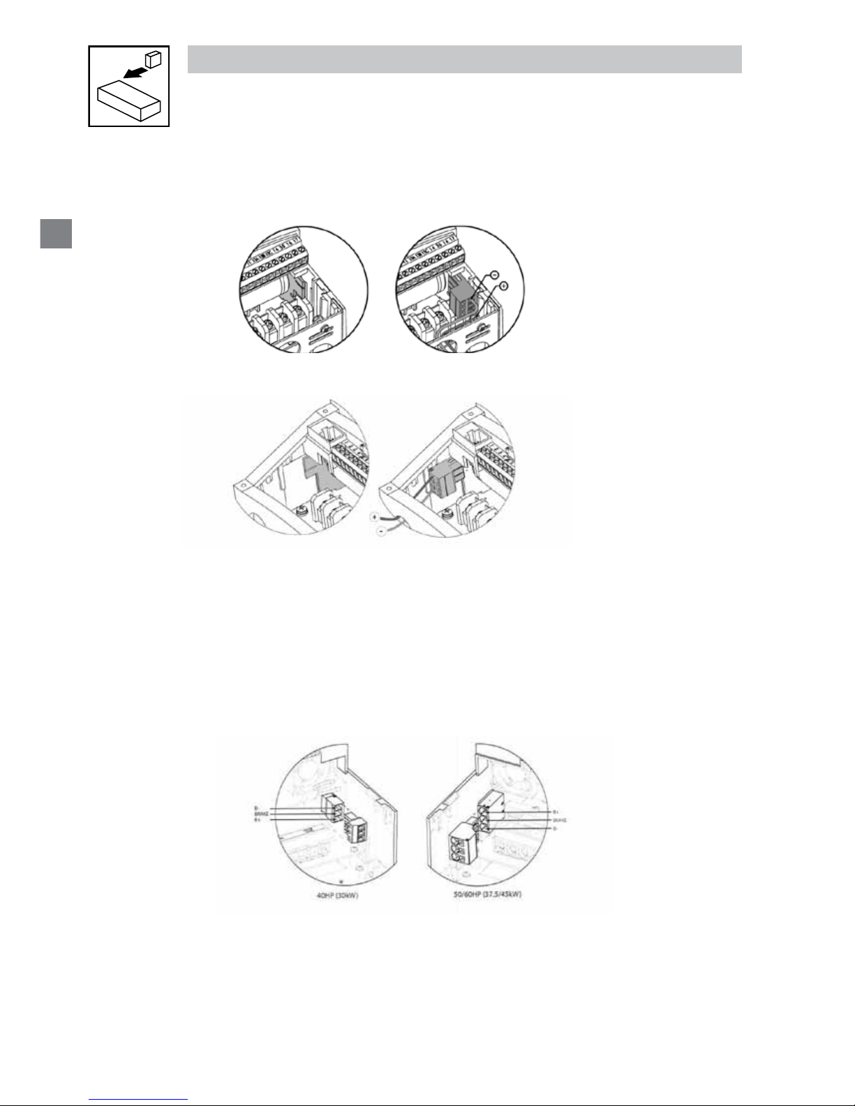
For NEMA 1 and NEMA 4X Drives rated up to 25 HP the Dynamic Brake connections are made as illustrated herein.
Refer to the SM2 and SM4 Dynamic Brake instructions for complete information.
NEMA 1 (IP31) up to 30 HP
NEMA 4 (IP65) up to 10 HP
The 40...40HP (30...45kW) models include a dynamic brake transitor as standard and only require the connection
of an external resistor kit for dynamic braking operation. The dynamic brake resistor connections for 40...60HP
(30...45kW) drives are standard built-in connections as illustrated in the diagram below. In the 40HP (30kW) model
drives, the dynamic brake connector is on the right-hand side of the drive and the terminals from top to bottom are
B-, BRAKE and B+. In the 50/60HP (37.5/45kW) model drives, the dynamic brake connector is on the left-hand side
of the drive and the terminals from top to bottom are B+, BRAKE and B-.
CALL NOW 800-985-6929
http://www.automatedpt.com
Email: charles@automatedpt.com
CALL NOW 800-985-6929
http://www.automatedpt.com
Email: charles@automatedpt.com
15
Installation
3.2.2 Fuses/cable cross-sections
Note
Observe local regulations.
Local codes may supersede these recommendations
Type
Recommendations
Fuse
Miniature
circuit
breaker
(1)
Fuse
(2)
or
Breaker
(3)
(N. America)
Input Power Wiring
(L1, L2, L3, PE)
[mm²] [AWG]
120V
1~
(1/N/PE)
174603 M10 A C10 A 10 A 1.5 14
174604, 174652.00 M16 A C16 A 15 A 2.5 14
174605, 174653.00 M25 A C25 A 25 A 4 10
240V
1~
(2/PE)
174603, 174604,174652, 174653
174607, 74606
M10 A C10 A 10 A 1.5 14
174605, 174608 M16 A C16 A 15 A 2.5 14
174609, 174651, 174654, 174657 M20 A C20 A 20 A 2.5 12
174610, 174658 M25 A C25 A 25 A 2.5 12
174611, 174659 M32 A C32A 32 A 4 10
240V
3~
(3/PE)
174607, 174608, 174606 M10 A C10 A 10 A 1.5 14
174609, 174610, 174612, 174613
174651, 174654, 174657, 174658
M16 A C16 A 12 A 1.5 14
174611, 174614, 74659 M20 A C20 A 20 A 2.5 12
174615, 174660 M32 A C32 A 32 A 4.0 10
174616, 174661 M40 A C40 A 35 A 6.0 8
174617, 174662 M50 A C50 A 45 A 10 8
174618 M80 A C80 A 80 A 16 8
174619 M100A C100A 90 A 16 8
400V
or 480V
3~(3/
PE)
174620, 174624, 174671, 174675 M10 A C10 A 10 A 1.5 14
174625, 174676 M16 A C16 A 20 A 2.5 14
174626, 174677 M20 A C20 A 20 A 2.5 14
174627, 174678 M25 A C25 A 25 A 4.0 10
174628 M40 A C40 A 40 A 4 8
174629 M50 A C50 A 50 A 10 8
174630 M63 A C63 A 70 A 10 6
174991 M80 A C80 A 80 A 16 6
174992 M100 A C100 A 100 A 25 4
174710 M125 A C125 A 125 A 35 2
174711 M180 A C160 A 150 A 35 1
600V
3~(3/
PE)
174631, 174632, 174633,
174663, 174665
M10 A C10 A 10 A 1.5 14
174634, 174666 M16 A C16 A 12 A 1.5 14
174635, 174667 M16 A C16 A 15 A 2.5 14
174636, 174668 M20 A C20 A 20 A 2.5 12
174637 M32 A C32 A 30 A 4 10
174638 M40 A C40 A 40 A 4 8
174639 M50 A C50 A 50 A 6 8
174993 M63 A C63 A 60 A 10 8
174994 M80 A C80 A 70 A 16 6
174712 M100 A C100 A 90 A 16 4
174713 M125 A C125 A 110 A 25 2
(1) Installations with high fault current due to large supply mains may require a type D circuit breaker.
(2) UL Class CC or T fast-acting current-limiting type fuses, 200,000 AIC, preferred. Bussman KTK-R, JJN or JJS or equivalent.
(3) Thermomagnetic type breakers preferred.
CALL NOW 800-985-6929
http://www.automatedpt.com
Email: charles@automatedpt.com
CALL NOW 800-985-6929
http://www.automatedpt.com
Email: charles@automatedpt.com
16
Installation
Observe the following when using Ground Fault Circuit Interrupters (GFCIs):
• Installation of GFCI only between supplying mains and controller.
• The GFCI can be activated by:
- capacitive leakage currents between the cable screens during operation (especially with long,
screened motor cables)
- connecting several controllers to the mains at the same time
- RFI lters
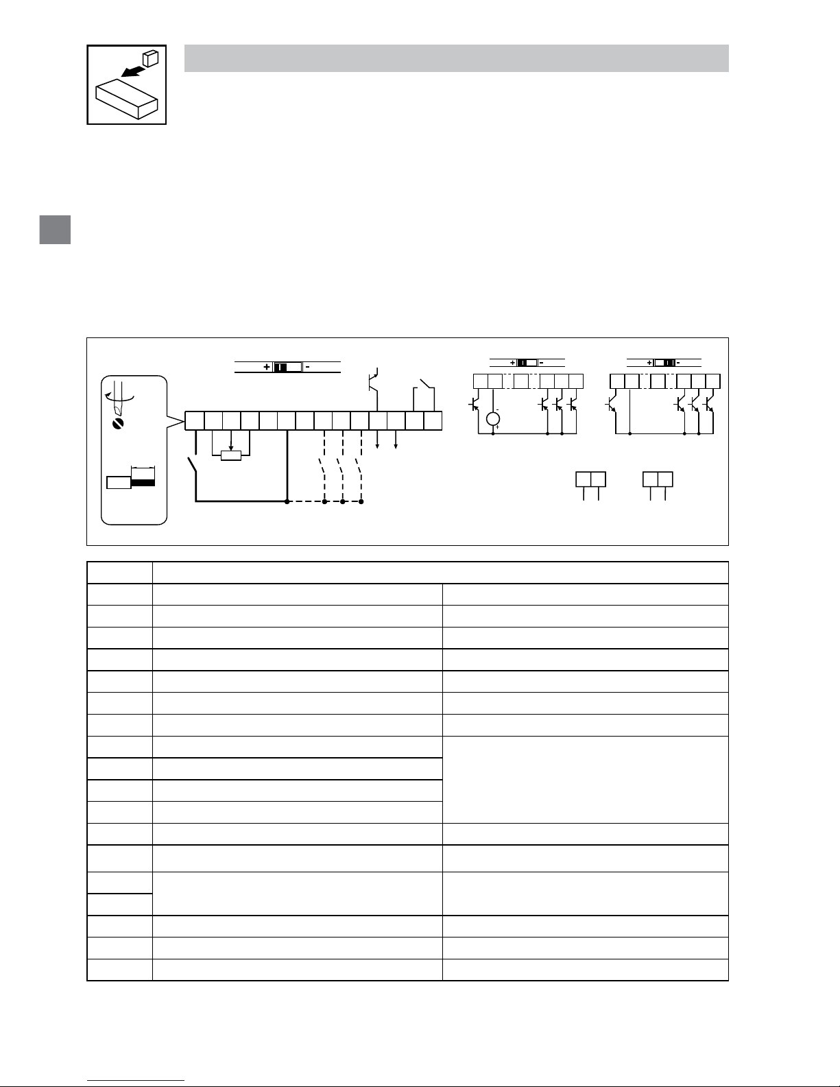
3.2.3 Control terminals
Control Terminal Strip for 0.33-10HP (0.25-7.5 kW):
625411
13A
13B
13C
17
512
14 30
16
AOUT
DIGOUT
2k … 10k
+10 V
AIN
AIN
COM
COM
ALsw
252
4 … 20 mA
52
0 … 10 V
0 … 5 V
1 2 4
13A 13B 13C
+12 VDC - 0 %
…
+30 VDC + 0 %
ALsw
+15V
1 2 4
13A 13B 13C
ALsw
COM
PNP NPN
4.5 lb-in
(0.5 Nm)
0.25 in (6 mm)
AWG 26…16
(<1mm²)
V0109
Terminal Data for control connections
1
Digital Input: Start/Stop input resistance = 4.3kΩ
2
Analog Common
5
Analog Input: 0...10 VDC input resistance: >50 kΩ
6
Internal DC supply for speed pot +10 VDC, max. 10 mA
25
Analog Input: 4...20 mA input resistance: 250Ω
4
Digital Reference/Common +15 VDC / 0 VDC, depending on assertion level
11
Internal DC supply for external devices +12 VDC, max. 50 mA
13A
Digital Input: Congurable with P121
input resistance = 4.3kΩ
13B
Digital Input: Congurable with P122
13C
Digital Input: Congurable with P123
13D*
Digital Input: Congurable with P124
14
Digital Output: Congurable with P142 DC 24 V / 50 mA; NPN
30
Analog Output: Congurable with P150…P155 0…10 VDC, max. 20 mA
16
Relay output: Congurable with P140
AC 250 V / 3 A
DC 24 V / 2 A … 240 V / 0.22 A, non-inductive
17
2*
Analog Common
TXA*
RS485 TXA
TXB*
RS485 TXB
* = Terminal is part of the terminal strip for the 15-25 HP models only
CALL NOW 800-985-6929
http://www.automatedpt.com
Email: charles@automatedpt.com
CALL NOW 800-985-6929
http://www.automatedpt.com
Email: charles@automatedpt.com
17
Commissioning
Control Terminal Strip for 15HP (11 kW) and Greater Drives:
625411
13A
13B
13C
TXA
512
14 30
2
AOUT
DIGOUT
2k … 10k
+10 V
+12 V
AIN
AIN
COM
COM
ALsw
17
16
TXB
13D
13D
13D
252
4 … 20 mA
52
0 … 10 V
1 2 4
13A 13B 13C
+12 VDC - 0 %
. . .
+30 VDC + 0 %
ALsw
+15V
1 2 4
13A 13B 13C
ALsw
COM
4.5 lb-in
(0.5 Nm)
0.25 in (6 mm)
AWG 26…16
(<1mm²)
The digital inputs can be congured for active-high or active-low by setting the Assertion Level
Switch (ALsw) and P120. If wiring to the drive inputs with dry contacts or with PNP solid state
switches, set the switch and P120 to “High” (+). If using NPN devices for inputs, set both to
“Low” (-). Active-high (+) is the default setting.
HIGH = +12 … +30 V
LOW = 0 … +3 V
Note
An F.AL fault will occur if the Assertion Level switch (ALsw) position does not match
the parameter P120 setting and P100 or any of the digital inputs (P121...P123) is set
to a value other than 0.
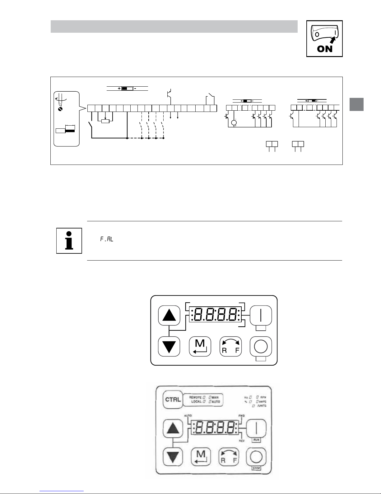
4 Commissioning
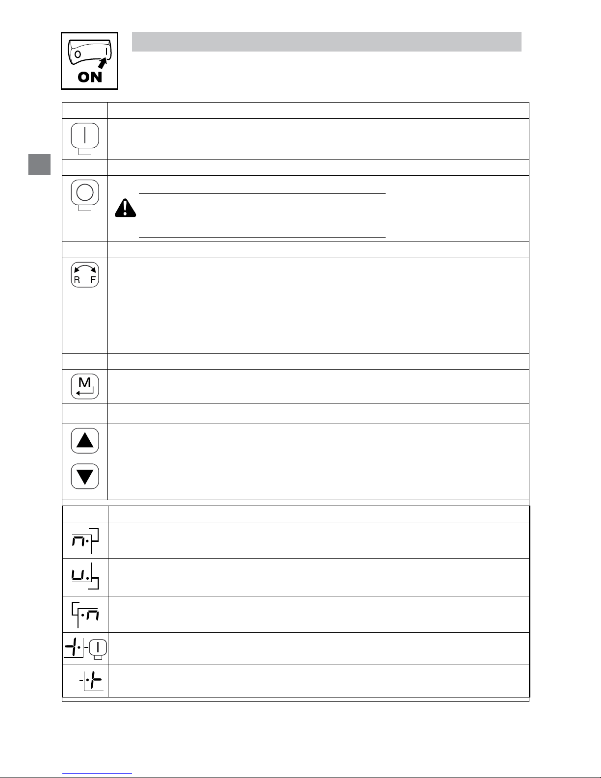
4.1 Local Keypad & Display
FWDAUTO
REV
STOP
RUN
V0105
15HP (1kW) and greater Models
CALL NOW 800-985-6929
http://www.automatedpt.com
Email: charles@automatedpt.com
CALL NOW 800-985-6929
http://www.automatedpt.com
Email: charles@automatedpt.com
18
Commissioning
Display START BUTTON
RUN
In Local Mode (P100 = 0, 4, 6), this button will start the drive.
STOP BUTTON
STOP
Stops the drive, regardless of which mode the drive is in.
WARNING!
When JOG is active, the STOP button will not stop the
drive!
ROTATION
In Local Mode (P100 = 0, 4, 6), this selects the motor rotation direction:
- The LED for the present rotation direction (FWD or REV) will be on
- Press R/F; the LED for the opposite rotation direction will blink
- Press M within 4 seconds to confirm the change
- The blinking direction LED will turn on, and the other LED will turn off
When rotation direction is changed while the drive is running, the commanded direction LED will blink
until the drive is controlling the motor in the selected direction.
MODE
Used to enter/exit the Parameter Menu when programming the drive and to enter a changed parameter
value.
UP AND DOWN BUTTONS
Used for programming and can also be used as a reference for speed, PID setpoint, or torque setpoint.
When the s and t buttons are the active reference, the middle LED on the left side of the display will
be on.
Display INDICATING LEDs (on 4-character display)
FWD
FWD LED: Indicate the present rotation direction is forward. Refer to ROTATION description above.
REV
REV LED: Indicate the present rotation direction is reverse. Refer to ROTATION description above.
AUTO
AUTO LED: Indicates that the drive has been put into Auto mode from one of the TB13 inputs (P121…
P124 set to 1…7). Also indicates that PID mode is active (if enabled).
RUN
RUN LED: Indicates that the drive is running.
s t LED: Indicates that the s t are the active reference.
CALL NOW 800-985-6929
http://www.automatedpt.com
Email: charles@automatedpt.com
CALL NOW 800-985-6929
http://www.automatedpt.com
Email: charles@automatedpt.com
19
Commissioning
NOTE
If the keypad is selected as the auto reference (P121…P124 is 6) and the
corresponding TB-13 input is closed, the AUTO LED and s t LEDs will both be on.
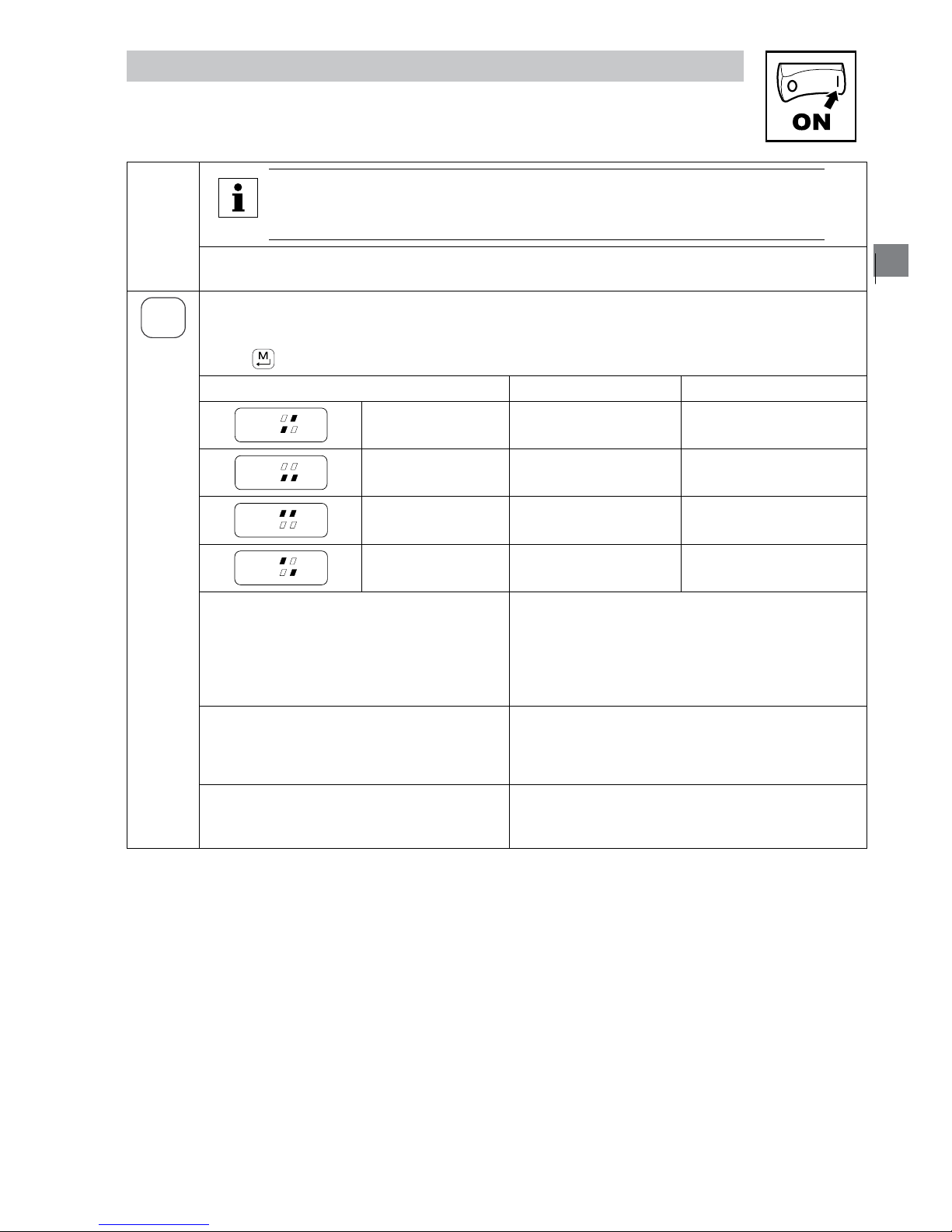
FUNCTIONS THAT FOLLOW ARE APPLICABLE TO SM2 DRIVES 15HP (11kW) AND GREATER
CTRL
CTRL
The CTRL pushbutton selects the start and speed reference control sources for the drive.
Press [
] mode button to accept the new control mode selection.
CTRL LEDs
START CONTROL REFERENCE CONTROL
REMOTE
LOCAL
MAN
AUTO
[LOCAL] [MAN]
Keypad P101 Settings
REMOTE
LOCAL
MAN
AUTO
[LOCAL] [AUTO]
Keypad Terminal 13x Settings
REMOTE
LOCAL
MAN
AUTO
[REMOTE] [MAN]
Terminal Strip P101 Settings
REMOTE
LOCAL
MAN
AUTO
[REMOTE] [AUTO]
Terminal Strip Terminal 13x Settings
If P100 = 6 the CTRL button is used to toggle
start control between the terminal strip
[REMOTE] and the keypad [LOCAL]
- REM/LOC LED indicating the present start control source
is ON
- Press [CTRL]; the LED for other start control source will
blink
- Press [M] within 4 sec to confirm the change
- Blinking LED will turn ON (the other LED will turn OFF)
If P113 = 1 the CTRL button is used to toggle
reference control between the TB-13x setup
[AUTO] and P101 [MANUAL]
- AUT/MAN LED indicating present reference control is ON
- Press [CTRL]; the other reference control will blink
- Press [M] within 4 sec to confirm change
- Blinking LED will turn ON (the other LED will turn OFF)
If P100 = 6 and P113 = 1, it is possible to
change the start and reference control sources
at the same time
CALL NOW 800-985-6929
http://www.automatedpt.com
Email: charles@automatedpt.com
CALL NOW 800-985-6929
http://www.automatedpt.com
Email: charles@automatedpt.com
20
Commissioning
Display START CONTROL
The REMOTE/LOCAL LEDs indicate the current start control source. If the start control source is a
remote keypad or the network, then both LEDs will be OFF.
REFERENCE CONTROL
The AUTO/MANUAL LEDs indicate the current reference control source.
IF P113 = 0 or 2, the AUTO/MANUAL LEDs will match the AUTO LED on the 4-character display. IF
P113 = 0 and no AUTO reference has been setup on the terminal strip, the MANUAL LED will turn ON
and the AUTO LED will turn OFF.
IF P113 = 1, the AUTO/MANUAL LEDS show the commanded reference control source as selected by
the [CTRL] button. If the [CTRL] button is used to set the reference control source to AUTO but no
AUTO reference has been setup on the terminal strip, reference control will follow P101 but the AUTO
LED will remain ON.
UNITS LEDs
HZ: current display value is in Hz In Speed mode, if P178 = 0 then HZ LED will be ON.
If P178 > 0, the Units LEDs follow the setting of P177
when the drive is in run (non-programming) mode.
In Torque mode, the HZ LED will be ON when the drive
is in run (non-programming) mode.
In Pid mode, the Units LEDs follow the setting of P203
when the drive is in run (non-programming) mode.
If P179 > 0, the Units LEDs will show the unit of the
diagnostic parameter that is being displayed.
%: current display value is in %
RPM: current display value is in RPM
AMPS: current display value is in Amps
/UNITS current display value is a per unit (i.e./
sec, /min, /hr, etc.)
4.2 Drive Displays and Modes of Operation
Speed Mode Display
In the standard mode of operation, the drive frequency output is set directly by the selected
reference (keypad, analog reference, etc.). In this mode, the drive display will show the drive’s
output frequency.
PID Mode Display
When the PID mode is enabled and active, the normal run display shows the actual PID setpoint.
When PID mode is not active, the display returns to showing the drive’s output frequency.
Torque Mode Display
When the drive is operating in Vector Torque mode, the normal run display shows the drive’s
output frequency.
Alternate (Run-Screen) Display
When P179 (Run Screen Display) is set to a value other than 0, one of the diagnostic parameters
(P501...P599) is displayed. Example: if P179 is set to 1, then diagnostic parameter P501 (Software
version) is displayed. If P179 = 2, then P502 (Drive ID) is displayed.
CALL NOW 800-985-6929
http://www.automatedpt.com
Email: charles@automatedpt.com
CALL NOW 800-985-6929
http://www.automatedpt.com
Email: charles@automatedpt.com
 Loading...