

Page 1

ELECTRIC MOTORS, GEARMOTORS AND DRIVES
Variable Speed AC Motor Drives
Installation and Operation Manual
SM-Basic
Page 2

EC Declaration of Conformity
In accordance with EN45014:1998
We,
Leeson Electric Corporation
2100 Washington Street
Grafton, Wisconsin 53024
USA
declare under sole responsibility that the following equipment to which this declaration relates, meets the
essential health and safety requirements and is in conformity with the relevant sections of the applicable
EC standards and other normative documents. If changes are made to the product that is covered by this
declaration of conformity, the declaration of conformity is no longer valid.
Equipment Type:
AC Variable Frequency Motor Drives:
174374.00 174375.00 174376.00 174377.00 174378.00
174379.00 174380.00 174381.00 174382.00 174383.00
174384.00 174385.00 174386.00 174387.00 174388.00
EC Directives:
By virtue of this conformity, the products are deemed to comply with the provisions of the Council of
European Communities Directives listed, provided installations are carried out in accordance with the
manufacturer’s instructions.
1) Low Voltage Directive 73/23/EEC as amended 93/68/EEC
2) Electromagnetic Compatibility Directive 89/336/EEC as amended 92/31/EEC
Harmonized Standards Used:
EN50081-2*: Electromagnetic Compatibility — Generic Emission Standard; Part 2: Industrial
Environment
EN50082-2*: Electromagnetic Compatibility — Generic Emission Standard; Part 2: Industrial
Environment
EN50178; 1998 Electronic Equipment for use in Power Installations
Authorized Representative:
* with suitable filters that are properly installed
Ms. Elisa Basso
Leeson Electric International Phone: (+39) 0-51-732-247
Via Caduti Di Sabbiuno 11/D-E Fax: (+39) 0-51-734-943
40011 Anzola Emilia Bologna
Italy
Dated this 2stday of May 2000.
Revision: 00, 5/02/2000
Peter F. Hennig
Senior Design Engineer
Page 3

Manual Number: IMSN01
TABLE OF CONTENTS
1.0 GENERAL..................................................................................... 1
2.0 SM-Basic DIMENSIONS................................................... 2
3.0 SM-Basic MODEL DESIGNATION CODE.................... 3
4 . 0 SM-Basic SPECIFICATIONS............................................ 3
5.0 SM-Basic RATINGS............................................................ 4
6.0 INSTALLATION........................................................................... 5
7.0 INPUT AC POWER REQUIREMENTS..................................... 7
8.0 POWER WIRING ......................................................................... 8
9.0 SM-Basic POWER WIRING DIAGRAM........................ 9
10.0 CONTROL WIRING.................................................................... 10
11.0 SM-Basic CONTROL WIRING DIAGRAMS................. 1 3
12.0 INITIAL POWER UP AND MOTOR ROTATION................... 16
13.0 PROGRAMMING THE SM Basic DRIVE..................... 18
14.0 PARAMETER MENU.................................................................. 21
15.0 DESCRIPTION OF PARAMETERS.......................................... 23
16.0 TROUBLESHOOTING..................................................... 37
17.0 SM-Basic DISPLAY MESSAGES.................................... 3 9
18.0 USER SETTING RECORD.............................................. 41
Page 4
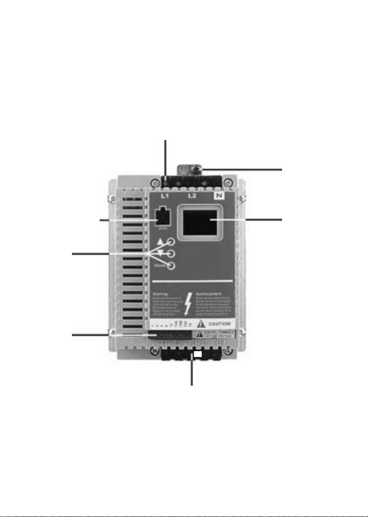
THE SM-Basic SUB-MICRO DRIVE
INPUT POWER TERMINALS
ELECTRONIC
PROGRAMMING
MODULE (EPM)
PROGRAMMING
BUTTONS
CONTROL
TERMINAL
STRIP
GROUND
LUG
2-DIGIT LED
DISPLAY
OUTPUT (MOTOR) TERMINALS
Page 5

1.0 GENERAL
1.1 PRODUCTS COVERED IN THIS MANUAL
This manual covers the Leeson Electric Corporation SM-Basic Series
Variable Frequency Drive.
1.2 PRODUCT CHANGES
Leeson Electric Corporation reserves the right to discontinue or make modifications to the
design of its products without prior notice, and holds no obligation to make modifications to
products sold previously. Leeson Electric Corporation also holds no liability for losses of any
kind which may result from this action.
1.3 WARRANTY
Leeson Electric Corporation warrants the SM-Basic AC motor control to be free of defects in
material and workmanship for a period of twelve months from the date of sale to the user, or
eighteen months from the date of shipment, which ever occurs first. If an SM-Basic motor
control, under normal use, becomes defective within the stated warranty time period, contact
Leeson Electric's Service Department for instructions on obtaining a warranty replacement
unit. Leeson Electric Corporation reserves the right to make the final determination as to the
validity of a warranty claim, and sole obligation is to repair or replace only components which
have been rendered defective due to faulty material or workmanship. No warranty claim will be
accepted for components which have been damaged due to mishandling, improper installation,
unauthorized repair and/or alteration of the product, operation in excess of design specifications
or other misuse, or improper maintenance. Leeson Electric Corporation makes no warranty
that its products are compatible with any other equipment, or to any specific application, to
which they may be applied and shall not be held liable for any other consequential damage or
injury arising from the use of its products.
This warranty is in lieu of all other warranties, expressed or implied. No other person, firm or
corporation is authorized to assume, for Leeson Electric Corporation, any
other liability in connection with the demonstration or sale of its products.
1.4 RECEIVING
Inspect all cartons for damage which may have occurred during shipping. Carefully unpack equipment
and inspect thoroughly for damage or shortage. Report any damage to carrier and/or shortages to
supplier. All major components and connections should be examined for damage and tightness, with
special attention given to PC boards, plugs, knobs and switches.
1.5 CUSTOMER MODIFICATION
Leeson Electric Corporation, its sales representatives and distributors, welcome the opportunity
to assist our customers in applying our products. Many customizing options are available to aid
in this function. Leeson Electric Corporation cannot assume responsibility for any modifications
not authorized by its engineering department.
1
Page 6
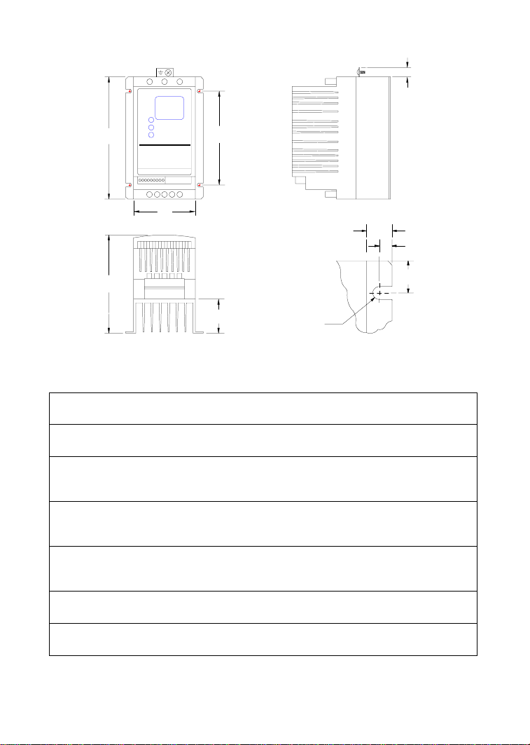
2.0 SM-Basic DIMENSIONS
0.38"
H
W
D
INPUT
HP VOLTAGE MODEL H W D P R
0.25 120/208/240 174374 5.75 2.88 3.76 0.80 4.37
208/240 174378 5.75 2.88 3.76 0.80 4.37
0.5 120/208/240 174375 5.75 2.88 3.76 0.80 4.37
208/240 174379 5.75 2.88 3.76 0.80 4.37
400/240 174384 5.75 2.88 3.76 0.80 4.37
1 120/208/240 174376 5.75 3.76 5.24 1.90 4.37
400/480 174380 5.75 2.88 4.56 1.60 4.37
480/590 174385 5.75 2.88 4.56 1.60 4.37
1.5 120/208/240 174445 5.75 3.76 5.24 1.90 4.37
208/240 174381 5.75 3.76 5.24 1.90 4.37
208/240 174386 5.75 2.88 5.56 2.60 4.37
2 208/240 174382 5.75 3.76 5.24 1.90 4.37
208/240 174387 5.75 2.88 5.56 2.60 4.37
3 208/240 174383 5.75 3.76 6.74 3.40 4.37
208/240 174388 5.75 3.76 6.74 2.60 4.37
R
0.38"
0.18"
0.69"
P
0.19"
Dia. Slot
Mounting Tab Detail
2
Page 7

3.0 SM-Basic MODEL DESIGNATION CODE
4.0 SM-Basic SPECIFICATIONS
Storage Tem perat ure -20 t o 70 C
Ambient Operating T em perat ure 0 t o 50 C (up to 6 k H z c arrier, derate abov e 6 k H z )
Ambient H um idit y < 95% (non-condensing)
Altitude 3300 ft (1000 m ) abov e s ea level (w it hout derating)
Input Line Voltages 120/208/240 Vac s ingle phase, 208/ 240 Vac t hree phase
Input Volt age Tolerance +10%, -15%
Input F requency Toleranc e 48 to 62 Hz
Output W ave F orm Sine Coded PWM
Output F requency 0 - 99 Hz
Carrier Frequency 4 kHz t o 10 k H z
Service F act or 1.00 (up to 6 kH z c arrier, derate abov e 6 kH z)
Effic ienc y Up to 98%
Power Fac t or (dis placem ent ) 0.96 or bett er
Overload Current C apac it y 150% for 60 sec onds, 180% f or 30 s ec onds
Speed Reference F ollower Speed Potentiomet er, 0-10 VDC (mus t be isolated)
Power Su pply f or Aux iliar y R elay 50 m A a t 12 VD C
Digital Out put Circuit rat ed 50 m A and 30 VD C m ax (t o drive aux iliary r elay)
1
WARNING: Control terminals are not isolated from line voltage! Do not touch!
1
1
3
Page 8

5.0 SM-Basic RATINGS
MODEL (120/208/240 Vac, 50-60 Hz) (0-200/230 Vac) HEAT LOSS
INPUT OUTPUT
MODEL
NUMBER
FOR MOTORS
RATED
HP kW
INPUT
PHASE
CURRENT
(AMPS)
(NOTE 1)
POWER
(kVA)
CURRENT
(AMPS)
(NOTE 1)
WATTS
(NOTE 3)
174374 0.25 0.20 1 6.0/3.5/3.0 0.72 1.4/1.6/1.4 21
174375 0.5 0.37 1 9.2/5.3/4.6 1.1 2.2/2.5/2.2 28
174376 1.0 0.75 1 15.8/9.1/7.9 1.9 4.0/4.6/4.0 46
174377 1.5 1.1 1 21.3/12.3/10.7 2.6 5.4/6.2/5.4 66
NOTE 1: The first current rating listed is for 120 Vac input, the second current rating is for 208 Vac input,
and the third current rating is for 240 Vac input. 120 Vac input yields 230 Vac output.
INPUT OUTPUT
MODEL (208/240 Vac, 50-60 Hz) (0-200/230 Vac) HEAT LOSS
MODEL
NUMBER
FOR MOTORS
RATED
HP kW
INPUT
PHASE
CURRENT
(AMPS)
(NOTE 1)
POWER
(kVA)
CURRENT
(AMPS)
(NOTE 1)
WATTS
(NOTE 3)
174378 0.25 0.20 1 3.6/3.2 0.76 1.6/1.4 19
174379 0.5 0.37 1 5.4/4.7 1.2 2.4/2.2 26
174384 3 3.1/2.7 1.1 24
174380 1 0.75 1 9.7/8.4 2.1 4.6/4.0 47
174385 3 5.5/4.8 2.0 39
174381 1.5 1.1 1 12.4/10.8 2.6 6.2/5.4 74
174386 3 7.1/6.3 2.6 62
174382 2 1.5 1 14.8/12.9 3.1 7.8/6.8 86
174387 3 9.1/7.9 3.2 78
174383 3 2.2 1 19.7/17.1 4.1 11.0/9.6 130
174388 3 12.4/10.8 4.4 117
NOTE 1: Models are rated for use with single and three phase input.
NOTE 2: The higher current rating is for 208 Vac input and the lower current rating is for 240 Vac input.
NOTE 3: Values are worst-case (not typical) for 6 kHz carrier frequency at full speed and full load.
4
Page 9

6.0 INSTALLATION
SM-Basic drives are intended for inclusion within other equipment, by professional electrical
installers. They are not intended for stand-alone operation.
DRIVES MUST NOT BE INSTALLED WHERE SUBJECTED TO ADVERSE ENVIRONMENTAL
CONDITIONS SUCH AS: COMBUSTIBLE, OILY, OR HAZARDOUS VAPORS OR DUST;
EXCESSIVE MOISTURE OR DIRT; VIBRATION; EXCESSIVE AMBIENT TEMPERATURES.
CONSULT AC TECHNOLOGY FOR MORE INFORMATION ON THE SUITABILITY OF A
DRIVE TO A PARTICULAR ENVIRONMENT.
Hazard of electrical shock! The SM-Basic control terminals are not isolated from line voltage!
Line voltage is present between the control terminals and ground. Do not touch!
Disconnect input power and wait three minutes before making connections to the control terminals.
Devices (such as switches, pushbuttons, potentiometers, relays, etc) and wiring connected to the
control terminals are hot to ground and must have an insulation rating of at least 240 Vac or a
dielectric rating of at least 1500 volts to prevent damage to equipment and/or injury to personnel.
SM-Basic models are suitable for UL pollution degree 2 environment only, and MUST be
installed in an electrical enclosure which will provide complete mechanical protection and will
maintain the internal temperature within the drive’s ambient operating temperature rating. All
drive models MUST be mounted in a vertical position for proper heatsink cooling.
Maintain a minimum spacing around the drive of at least one inch on each side and two inches on the
top and bottom. Allow more spacing if the drive is mounted next to other heat-producing equipment.
Do not mount drives above other drives or heat producing equipment. Fans or blowers should be
used to insure proper cooling in tight quarters.
NOTE!
WARNING!
WARNING!
In order to properly size an enclosure, the heat generated by the drive(s) must be known. Refer to the
HEAT LOSS column in Section 5.0 - SM-Basic RATINGS. An enclosure manufacturer can then
determine the required enclosure size based on the total heat generated inside the enclosure
(from the drive(s) and other heat sources), the maximum allowable temperature inside the
enclosure, the maximum ambient temperature outside the enclosure, and the enclosure properties.
The SM-Basic Series is UL approved for solid state motor overload protection. Therefore, a
separate thermal overload relay is not required for single motor applications.
5
Page 10

6.1 INSTALLATION AFTER A LONG PERIOD OF STORAGE
Severe damage to the drive can result if it is operated after a long period of storage or inactivity
without reforming the DC bus capacitors!
If input power has not been applied to the drive for a period of time exceeding three years (due to
storage, etc), the electrolytic DC bus capacitors within the drive can change internally, resulting in
excessive leakage current. This can result in premature failure of the capacitors if the drive is operated
after such a long period of inactivity or storage.
In order to reform the capacitors and prepare the drive for operation after a long period of inactivity,
apply input power to the drive for 8 hours prior to actually operating the motor.
6.2 EXPLOSION PROOF APPLICATIONS
Explosion proof motors that are not rated for inverter use lose their certification when used for variable
speed. Due to the many areas of liability that may be encountered when dealing with these applications,
the following statement of policy applies:
“Leeson Electric Corporation inverter products are sold with no warranty of
fitness for a particular purpose or warranty of suitability for use with explosion
proof motors. Leeson Electric Corporation accepts no responsibility for any
direct, incidental or consequential loss, cost, or damage that may arise through
the use of its AC inverter products in these applications. The purchaser expressly
agrees to assume all risk of any loss, cost, or damage that may arise from such
application. Leeson Electric Corporation or Leeson Electric Corporation’s
engineering department will not knowingly approve applications involving
explosion proof motors.”
WARNING!
6
Page 11

7.0 INPUT AC POWER REQUIREMENTS
Hazard of electrical shock! Capacitors retain charge after power is removed. Disconnect incoming
power and wait until the voltage between terminals B+ and B- is 0 VDC before servicing the drive.
The input voltage must match the nameplate voltage rating of the drive. Voltage fluctuation must not
vary by greater than 10% overvoltage or 15% undervoltage.
NOTE: Drives with dual input voltage ratings must be programmed for the proper supply voltage
(refer to Parameter 01 - LINE VOLTAGE SELECTION in Section 15.0 - DESCRIPTION OF
PARAMETERS).
The drive is suitable for use on a circuit capable of delivering not more than 5,000 RMS symmetrical
amperes at the drive’s rated voltage.
Three phase voltage imbalance must be less than 2.0% phase to phase. Excessive phase to phase
imbalance can cause severe damage to the drive.
Motor voltage should match line voltage in normal applications. The drive’s maximum output voltage
will equal the input voltage. Use extreme caution when using a motor with a voltage rating which is
different from the input line voltage.
7.1 INPUT VOLTAGE RATINGS
SM-Basic Series drives are rated for 120/208/240 Vac, single phase, 50-60 Hz input. The
drive will function with input voltage of 120 Vac (+10%, -15%), at 48 to 60 Hz, or with input
voltage of 208 to 240 Vac (+ 10%, - 15%), at 48 to 62 Hz.
SM-Basic Series drives are rated for 208/240 Vac, single phase, 50-60 Hz input. The drive
will function with input voltages of 208 to 240 Vac (+10%, -15%), at 48 to 62 Hz.
WARNING!
SM-Basic Series drives are rated for 208/240 Vac, three phase, 50-60 Hz input. The drive will
function with input voltages of 208 to 240 Vac (+ 10%, - 15%), at 48 to 62 Hz.
NOTE: Parameter 01 - LINE VOLTAGE SELECTION must be programmed according to the applied
input voltage. See Section 15.0 - DESCRIPTION OF PARAMETERS.
7.2 INPUT FUSING AND DISCONNECT REQUIREMENTS
A circuit breaker or a disconnect switch with fuses must be provided in accordance with the National
Electric Code (NEC) and all local codes.
The SM-Basic drive is capable of withstanding up to 150% current overload for 60 seconds.
Select a fuse or magnetic trip circuit breaker rated at 1.5 times the input current rating of the
drive (the minimum fuse size should be 10 amps, regardless of input current rating). Refer to
Section 5.0 - SM-Basic RATINGS.
7
Page 12

Minimum voltage rating of the protection device should be 250 Vac for 120/208/240 Vac and 208/
240 Vac rated drives.
UL Class CC fast-acting, current limiting type fuses should be used when input fusing is required.
Select fuses with low I
2
T values, rated at 200,000 AIC. Recommended fuses are Bussman KTK-R.
Similar fuses with equivalent ratings by other manufacturers may also be acceptable.
8.0 POWER WIRING
Hazard of electrical shock! Capacitors retain charge after power is removed. Disconnect incoming
power and wait until the voltage between terminals B+ and B- is 0 VDC before servicing the drive.
Note drive input and output current ratings and check applicable electrical codes for required wire
type and size, grounding requirements, over-current protection, and incoming power disconnect,
before wiring the drive. Size conservatively to minimize voltage drop.
Strip off 0.20 to 0.25 inches of insulation for input power, output power, and DC Bus wiring. The
input power, output power, and DC Bus terminals must be tightened to a torque of 4.0 to 4.5 lb-in.
Input fusing and a power disconnect switch or contactor MUST be wired in series with terminals L1,
L2, and L3 for three phase input models. For 208/240 Vac single phase input models, use terminals
L1 and L2. For 120 Vac single phase input models, use terminals L1 and N. This disconnect must be
used to power down the drive when servicing, or when the drive is not to be operated for a long
period of time, but should not be used to start and stop the motor. Repetitive cycling of a disconnect
or input contactor (more than once every two minutes) may cause damage to the drive.
8.1 WIRING FOR SINGLE PHASE OR THREE PHASE INPUT
If the drive is rated for 120/208/240 Vac single phase input, wire the input to terminals L1 and
N for 120 Vac voltage, or wire to terminals L1 and L2 (do not wire to N) for 208/240 Vac input
voltage. Refer to Section 9.0 - SM-Basic POWER WIRING DIAGRAM.
WARNING!
If the drive is rated for 208/240 Vac single phase input, wire the input to terminals L1 and L2.
If the drive is rated for three phase input, wire the input to terminals L1, L2, and L3.
All three power output wires, from terminals T1, T2, and T3 to the motor, must be kept tightly
bundled and run in a separate conduit away from all other power and control wiring.
Do not install contactors or disconnects between the drive and motor without consulting Leeson
Electric Corporation for more information.
8
Page 13
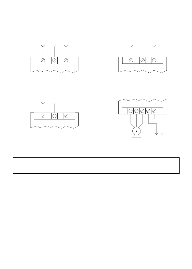
9.0 SM-Basic POWER WIRING DIAGRAM
THREE PHASE INPUT
(where applicable)
L1 L2 L3
208/240 Vac SINGLE PHASE INPUT
(where applicable)
L1 L2 L3*
120 Vac SINGLE PHASE INPUT
(where applicable)
L1 L2 N
OUTPUT (ALL)
T1 T2 T3 B- B+
+
3 PHASE
AC MOTOR
WARNING!
Do not connect incoming AC power to output terminals T1, T2, or T3. Severe damage to the drive
will result.
DC BUS
VOLTAGE
NOTES:
1. WIRE AND GROUND IN ACCORDANCE WITH NEC OR CEC, AND ALL APPLICABLE
LOCAL CODES.
2. Motor wires MUST be run in a separate steel conduit away from control wiring and incoming AC
power wiring.
3. Do not install contactors between the drive and the motor without consulting Leeson
Electric Corporation for more information. Failure to do so may result in drive damage.
4. Use only UL and CSA listed and approved wire.
5. Minimum wire voltage ratings: 300 V for 120, 208 and 240 Vac systems.
6. Wire gauge must be based on a minimum of 125% of the rated input/output current of the drive,
and a minimum 75°C insulation rating. Use copper wire only.
7. Strip off 0.20 to 0.25 inches of insulation for input power, output power, and DC Bus wiring.
9
Page 14

10.0 CONTROL WIRING
Hazard of electrical shock! The SM-Basic control terminals are not isolated from line voltage!
Line voltage is present between the control terminals and ground. Do not touch!
Disconnect input power and wait three minutes before making connections to the control terminals.
Devices (such as switches, pushbuttons, potentiometers, relays, etc) and wiring connected to the
control terminals are hot to ground and must have an insulation rating of at least 240 Vac or a
dielectric rating of at least 1500 volts to prevent damage to equipment and/or injury to personnel.
10.1 CONTROL WIRING VS. POWER WIRING
External control wiring MUST be run in a separate conduit away from all other input and output
power wiring. If control wiring is not kept separate from power wiring, electrical noise may be
generated on the control wiring that will cause erratic drive behavior. Use twisted wires or shielded
cable rated for 300 VDC minimum (do not ground the shield).
10.2 SURGE SUPPRESION ON RELAYS
Current and voltage surges and spikes in the coils of contactors, relays, and solenoids, near or connected
to the drive, can cause erratic drive operation. Snubbers should be used on any coils associated with
the drive. For AC loads, snubbers should consist of a resistor and a capacitor in series across the coil.
For DC loads, a free-wheeling or flyback diode should be placed across the coil.
10.3 START/STOP CONTROL
There are various control schemes that allow for 2-wire and 3-wire Start/Stop circuits. Refer to the
wiring diagrams in Section 11.0 - SM-Basic CONTROL WIRING DIAGRAMS.
10.4 SPEED REFERENCE SIGNALS
WARNING!
SPEED POT Connect the wiper to terminal TB-5, and connect the high and low end leads to
0-10 VDC Wire the positive to terminal TB-5 and the negative to terminal TB-3. The 0-10
DO NOT connect the low side of the speed pot or 0-10 VDC signal to ground.
terminals TB-6 and TB-3, respectively. The speed pot can be 5kΩ up to 10kΩ.
VDC signal must be isolated, as the control terminals are at line voltage potential.
10
Page 15

10.5 SPEED REFERENCE SELECTION
If a speed pot is to be used to control the drive speed, terminal TB-13A, 13B, or 13C (Parameter 10,
11, or 12) may be programmed as the input select for the speed pot. When that TB-13 terminal is then
closed to TB-11, the drive will follow the speed pot input.
If the speed pot is not selected on the terminal strip using TB-13A, 13B, or 13C, speed control will
default to STANDARD mode, which is governed by the setting of Parameter 05 - STANDARD
SPEED SOURCE. The STANDARD SPEED SOURCE can be the I and J buttons on the front of
the drive, PRESET SPEED #1 (Parameter 31), or a speed pot.
PRESET SPEEDS
TB-13A can be programmed to select PRESET SPEED #1, TB-13B to select PRESET SPEED #2,
and TB-13C to select PRESET SPEED #3. There are a total of seven preset speeds, which are
activated by different combinations of contact closures between TB-13A, 13B, 13C and TB-11. Refer
to Parameters 31-37 in Section 15.0 - DESCRIPTION OF PARAMETERS.
JOG
TB-13B can be programmed to select either JOG FORWARD or JOG REVERSE. The Jog speed is
set by PRESET SPEED #2. Close TB-13B to TB-11 to JOG, and open the contact to STOP.
When operating in JOG mode, the STOP signal and the AUXILIARY STOP function (see Parameters
10-12) WILL NOT stop the drive. To stop the drive, remove the JOG command.
JOG REVERSE will operate the drive in reverse rotation even if ROTATION DIRECTION (Parameter
17) is set to FORWARD ONLY.
NOTE: If the drive is commanded to JOG while running, the drive will enter JOG mode and run at
PRESET SPEED #2. When the JOG command is removed, the drive will STOP.
MOTOR OPERATED POT (MOP) / FLOATING POINT CONTROL
TB-13B and TB-13C are required for this function, which controls the drive speed using normally
open contacts wired to the terminal strip. Program TB-13B for DECREASE FREQ, and program
TB-13C for INCREASE FREQ. Closing the contacts between the TB-13 terminals and TB-11 will
cause the speed setpoint to increase or decrease until the contact is opened. The INCREASE FREQ
function will only operate while the drive is running.
NOTE: If TB-13A, TB-13B, and TB-13C are all programmed to select speed references, and two or
three of the terminals are closed to TB-11, the higher terminal has priority and will override the
others. For example, if TB-13A is programmed to select a speed pot, and TB-13C is programmed to
select PRESET SPEED #3, closing both terminals to TB-11 will cause the drive to respond to PRESET
SPEED #3, because TB-13C overrides TB-13A.
WARNING!
11
Page 16

10.7 DRIVE STATUS DIGITAL OUTPUTS
There is one open-collector output at terminal TB-14. The open-collector circuit is a current-sinking
type rated at 30 VDC and 50 mA maximum.
The open-collector output can be programmed to indicate any one of the following: RUN, FAULT,
INVERSE FAULT, FAULT LOCKOUT, AT SPEED, ABOVE PRESET SPEED #3, CURRENT
LIMIT, AUTO SPEED MODE, and REVERSE. Refer to Parameter 06 in Section 15.0 DESCRIPTION OF PARAMETERS.
DIODE SNUBBER
(RECOMMENDED)
TB-11
RELAY COIL
TB-14
SCN TERMINAL STRIP
Hazard of electrical shock! The SCN control terminals are not isolated from line voltage! Line
WARNING!
voltage is present between the control terminals and ground. Do not touch!
Only use relays with an insulation rating of at least 240 Vac or a dielectric rating of at least 1500 volts
to prevent damage to equipment and/or injury to personnel.
NOTE: When the optional remote keypad is used, TB-14 is wired to the remote keypad and cannot
be used for status indication.
12
Page 17

11.0 SM-Basic CONTROL WIRING DIAGRAMS
11.1 TWO-WIRE START/STOP CONTROL
Hazard of electrical shock! The SM-Basic control terminals are not isolated from line voltage!
Line voltage is present between the control terminals and ground. Do not touch!
Disconnect input power and wait three minutes before making connections to the control terminals.
Devices (such as switches, pushbuttons, potentiometers, relays, etc) and wiring connected to the
control terminals are hot to ground and must have an insulation rating of at least 240 Vac or a
dielectric rating of at least 1500 volts to prevent damage to equipment and/or injury to personnel.
RUN
3
5 6 11 13A 13B 1413C
SPEED POT INPUT
SPEED POT COMMON
1
WARNING!
SPEED POT POWER SUPPLY
SPEED
POT
DIGITAL INPUT REFERENCE
TB-13A FUNCTION SELECT
(RUN REVERSE)
TB-13B FUNCTION SELECT
TB-13C FUNCTION SELECT
OPEN-COLLECTOR OUTPUT
MAINTAINED
RUN/STOP CONTACT
(FORWARD)
NOTES:
1. Close TB-1 to TB-11 to RUN, and open to STOP. TB-1 functions as a RUN input for two-wire
start/stop circuits, and a STOP input for three-wire start/stop circuits. Refer to Section 11.2.
2. If reverse direction is required, set ROTATION (Parameter 17) to FORWARD AND REVERSE
(02), and program TB-13A (Parameter 10) to RUN REVERSE (05). Close TB-13A to TB-11 to
RUN in the reverse direction, and open to STOP.
3. For speed pot control, set STANDARD SPEED SOURCE (Parameter 05) to SPEED POT (03).
MAINTAINED
RUN/STOP CONTACT
(REVERSE)
13
Page 18

11.2 THREE-WIRE START/STOP CONTROL
Hazard of electrical shock! The SM-Basic control terminals are not isolated from line voltage!
Line voltage is present between the control terminals and ground. Do not touch!
Disconnect input power and wait three minutes before making connections to the control terminals.
Devices (such as switches, pushbuttons, potentiometers, relays, etc) and wiring connected to the
control terminals are hot to ground and must have an insulation rating of at least 240 Vac or a
dielectric rating of at least 1500 volts to prevent damage to equipment and/or injury to personnel.
STOP
3
5 6 11 13A 13B 1413C
SPEED POT INPUT
SPEED POT COMMON
1
WARNING!
TB-13A FUNCTION SELECT
SPEED POT POWER SUPPLY
DIGITAL INPUT REFERENCE
(START REVERSE)
TB-13C FUNCTION SELECT
TB-13B FUNCTION SELECT
(START FORWARD)
OPEN-COLLECTOR OUTPUT
SPEED
POT
MOMENTARY
STOP CONTACT
NOTES:
1. Program TB-13C (Parameter 12) for START FORWARD (05).
2. If reverse direction is required, set ROTATION (Parameter 17) to FORWARD AND REVERSE
(02), and program TB-13A (Parameter 10) for START REVERSE (06).
3. Momentarily close TB-13C to TB-11 to START in the forward direction, or close TB-13A to
TB-11 to START in the reverse direction. Momentarily open TB-1 to TB-11 to STOP the drive.
4. For speed pot control, set STANDARD SPEED SOURCE (Parameter 05) to SPEED POT (03).
START CONTACT
14
REV FWD
MOMENTARY
Page 19

11.3 PRESET SPEEDS (WITH TWO-WIRE START/STOP CONTROL)
Hazard of electrical shock! The SM-Basic control terminals are not isolated from line voltage!
Line voltage is present between the control terminals and ground. Do not touch!
Disconnect input power and wait three minutes before making connections to the control terminals.
Devices (such as switches, pushbuttons, potentiometers, relays, etc) and wiring connected to the
control terminals are hot to ground and must have an insulation rating of at least 240 Vac or a
dielectric rating of at least 1500 volts to prevent damage to equipment and/or injury to personnel.
RUN
3
5 6 11 13A 13B 1413C
SPEED POT INPUT
SPEED POT COMMON
1
WARNING!
TB-13A FUNCTION SELECT
SPEED POT POWER SUPPLY
DIGITAL INPUT REFERENCE
(PRESET SPEED #1)
TB-13C FUNCTION SELECT
TB-13B FUNCTION SELECT
(PRESET SPEED #2)
(PRESET SPEED #3)
OPEN-COLLECTOR OUTPUT
SPEED
POT
MAINTAINED
RUN/STOP CONTACT
NOTES:
1. For preset speed control, all or some of the TB-13 terminals must be programmed as preset speed
selects. If only two or three preset speeds are required, only two of the TB-13 terminals must be
used. Refer to the table in the description of Parameters 31-37 in Section 15.0.
2. Program the PRESET SPEEDS (Parameters 31-37) to the desired values.
3. If speed pot control is desired when none of the preset speeds are selected (all preset speed selects
are open to TB-11), set STANDARD SPEED SOURCE (Parameter 05) to SPEED POT (03).
15
Page 20

12.0 INITIAL POWER UP AND MOTOR ROTATION
DO NOT connect incoming AC power to output terminals T1, T2, and T3! Severe damage to the
drive will result. Do not continuously cycle input power to the drive more than once every two
minutes. Damage to the drive will result.
Hazard of electrical shock! The SM-Basic control terminals are not isolated from line voltage!
Line voltage is present between the control terminals and ground. Do not touch!
Capacitors retain charge after power is removed. Disconnect input power and wait until the voltage
between terminals B+ and B- is 0 VDC before making control connections or servicing the drive.
Severe damage to the drive can result if it is operated after a long period of storage or inactivity
without reforming the DC bus capacitors!
If input power has not been applied to the drive for a period of time exceeding three years (due to
storage, etc), the electrolytic DC bus capacitors within the drive can change internally, resulting in
excessive leakage current. This can result in premature failure of the capacitors if the drive is operated
after such a long period of inactivity or storage.
In order to reform the capacitors and prepare the drive for operation after a long period of inactivity,
apply input power to the drive for 8 hours prior to actually operating the motor.
Before attempting to operate the drive, motor, and driven equipment, be sure all procedures pertaining
to installation and wiring have been properly followed.
WARNING!
WARNING!
WARNING!
If possible, disconnect the driven load from the motor. Verify that the drive input terminals (L1, L2,
and L3 or N) are wired to the proper input voltage per the nameplate rating of the drive.
Energize the incoming power line. The LED display will flash a two-digit number (15 in the example
below) that identifies the parameter version contained in the drive ("15" actually means parameter
version 315). The display should then read “- -", which indicates that the drive is in a STOP condition.
This is shown below:
Apply input power
Display flashes parameter
version (00-99)
Display then reads "- -"
16
Page 21

Follow the procedure below to check the motor rotation. This procedure assumes that the drive has
been powered up for the first time, and that none of the parameters have been changed.
1. Use the t button to decrease the speed setpoint to 0 Hz. The left decimal point will illuminate as
the speed setpoint is decreased.
Once 0 Hz is reached, the display will toggle between “00” and “- -”, which indicates that the
drive is in a STOP condition with a speed setpoint of 0 Hz.
2. Give the drive a START command. This can be done using one of several wiring methods
described in Section 11.0 - SM-Basic CONTROL WIRING DIAGRAMS. Once the START
command is issued, the display will read “00”, indicating that the drive is in a RUN condition
with a speed setpoint of 0 Hz.
3. Use the s button to increase the speed setpoint until the motor starts to rotate. The left decimal
point will light as the speed setpoint is increased.
4. If the motor is rotating in the wrong direction, give the drive a STOP command and remove
power from the drive. Wait three minutes for the bus capacitors to discharge, and swap any two
of the motor wires connected to T1, T2, and T3.
NOTE: The drive is phase insensitive with respect to incoming line voltage. This means that the
drive will operate with any phase sequence of the incoming three phase voltage. Therefore, to change
the motor rotation, the phases must be swapped at the drive output terminals or at the motor.
17
Page 22

13.0 PROGRAMMING THE SM-Basic DRIVE
The drive may be programmed by one of two methods: using the three buttons and 2-digit LED
display on the front of the drive, or programming the Electronic Programming Module (EPM) using
the optional EPM Programmer. This section describes programming the drive using the buttons and
display, which are shown below:
BUTTONS
Mode
To enter the PROGRAM mode to access the parameters, press the Mode button. This will activate
the PASSWORD prompt (if the password has not been disabled). The display will read “00” and the
upper right-hand decimal point will be blinking, as shown below:
Press Mode
Display reads "00"
Right decimal point blinks
Use the s and t buttons to scroll to the password value (the factory default password is “25”) and
press the Mode button. Once the correct password value is entered, the display will read "01", which
indicates that the PROGRAM mode has been accessed at the beginning of the parameter menu (01 is
the first parameter), and the upper right decimal point will turn on solid. This is shown below:
Use s and t to scroll to the
password value
Press Mode to enter password
DISPLAY
Parameter menu is accessed at the
first parameter
Upper right decimal point turns on solid.
18
Page 23

NOTE: If the display flashes “Er”, the password was incorrect, and the process to enter the password
must be repeated.
Use the s and t buttons to scroll to the desired parameter number. In the example below, Parameter
19 is being displayed, which is the ACCELERATION TIME of the drive:
Use s and t to scroll to the desired
parameter number
Once the desired parameter number is found, press the Mode button to display the present parameter
setting. The upper right-hand decimal point will begin blinking, indicating that the present parameter
setting is being displayed, and that it can be changed by using the s and t buttons.
Press Mode to display present parameter
setting (present example setting is 15)
Right decimal point blinks
Use s and t to change setting
(example setting changed to 30)
Press Mode to store new setting
Pressing the Mode will store the new setting and also exit the PROGRAM mode. To change another
parameter, press the Mode key again to re-enter the PROGRAM mode (the parameter menu will be
accessed at the parameter that was last viewed or changed before exiting). If the Mode key is pressed
within two minutes of exiting the PROGRAM mode, the password is not required access the parameters.
After two minutes, the password must be entered in order to access the parameters again.
19
Page 24

13.2 ELECTRONIC PROGRAMMING MODULE (EPM)
Every SM-Basic Series drive has an Electronic Programming Module (EPM) installed on the
main control board. The EPM stores the user’s parameter settings and special OEM default
settings (if programmed). The EPM is removable, allowing it to be installed in another drive for
quick set-up. For example, if a drive is being replaced with a new one, the EPM can be taken out
of the first drive and installed in the new drive. Downtime is minimized because the new drive
does not require programming - it is ready to run when the EPM is installed.
The SM-Basic Series drive contains two or three sets of parameter values, depending on whether
the drive has been programmed with optional OEM default settings. The first set of values is the
factory default settings, which are permanently stored on the main control board and cannot be
changed. The second set of values is the user settings, which are stored in the EPM. When the
drive leaves the factory, the user settings are the same as the factory default settings, but the user
settings can be changed to configure the drive for a particular application. The optional third set
of values is the OEM default settings, which are also stored in the EPM. OEM default settings
are typically used in cases where many drives are used for the same application, which requires
that all of the drives have the same parameter settings. The OEM default settings cannot be
changed without the optional EPM Programmer. The drive can be programmed to operate
according to the user settings or the OEM default settings (see Parameter 48 in Section 15.0).
NOTE: The drive will not operate without the EPM installed. The drive will display “F1” if the
EPM is missing or damaged.
Do not remove the EPM while power is applied to the drive. Damage to the EPM and/or drive may
result.
An EPM Programmer is available as an option from SM-Basic, which has the ability to quickly
and easily program many SM-Basic drives for the same configuration. Once a “master” EPM is
programmed with the desired parameter settings, the EPM Programmer can copy those settings
to other EPMs, allowing many drives to be configured very quickly. Please consult the EPM
Programmer Instruction Manual or contact the factory for more information.
If the OEM settings in the EPM become corrupted, the drive will operate normally, until an attempt
is made to perform a RESET OEM using Parameter 48 - PROGRAM SELECTION. The drive will
then flash “GF” to indicate that the OEM settings are no longer valid. This will require that the EPM
be re-programmed using the optional EPM Programmer.
If the OEM settings and the user settings are both corrupted, the drive will display “GF” immediately
and the drive will require a RESET 60 or RESET 50 using Parameter 48 - PROGRAM SELECTION.
Once the RESET is performed, the parameters can then be programmed individually to match the
OEM default settings. This will allow the drive to operate as if it were in OEM mode, even though it
is actually operating in USER mode. Refer to Parameter 48 in Section 15.0 - DESCRIPTION OF
PARAMETERS.
NOTE: The drive will also display “GF” if a RESET OEM or OPERATE WITH OEM SETTINGS
is attempted when the drive is not equipped with the OEM default option.
WARNING!
20
Page 25

14.0 PARAMETER MENU
FACTORY
FACTORY
FACTORYFACTORY
NO.
NO. PARAMETER NAME
PARAMETER NAME RANGE OF ADJUSTMENT
NO.NO.
PARAMETER NAMEPARAMETER NAME
01 LINE VOLTAGE HIGH (01), LOW (02) HIGH (01)
02 CAR R I ER F R EQU EN C Y 4kHz (01), 6 k H z (02), 8 k H z (03), 10 k H z (04) 6 kHz (02)
03 START M ET H OD NORMAL (01), ST AR T ON POW ER UP (02), NORM AL (01)
FLYIN G REST AR T 1 (05), F LYIN G R ESTAR T 2 (06),
04 STOP METH OD COAST (01), C OAST W I TH DC BRAKE (02), COAST (01)
05 STAN D AR D SPEE D KEYPAD (01), PR ESET #1 (02), KEYPAD (01)
SOURC E SPEED POT (03)
06 TB-14 OUT PU T NONE (01), R U N (02), F AU LT (03), NON E (01)
10 TB-13A FU N C T I ON NONE (01), SPEED POT (02), N ON E (01)
SELECT PRESET SPEED #1 (03), ST ART FOR W AR D (04),
11 TB-13B FU N C T I ON NONE (01), SPEED POT (02), N ON E (01)
SELEC T PRESET SPEE D # 2 (03), D EC R EASE F R EQ (04) ,
12 TB-13C F U N C T I ON NONE (01), SPEED POT (02), N ON E (01)
SELEC T PRESE T SP EED #3 (03), I N C R EASE F R EQ (04) ,
RANGE OF ADJUSTMENT
RANGE OF ADJUSTMENTRANGE OF ADJUSTMENT
START W IT H D C BRAKE (03),
AUT O R EST AR T W I T H D C BR AKE (04 ),
FLYING RESTART 3 (07)
RAMP (03), R AM P W IT H DC BR AKE (04)
INVERSE FAULT (04), FAULT LOCKOUT (05),
AT SET SPE ED (06), ABOVE PR ES ET #3 (07),
CURREN T LI M I T (08), AUT O SPEED (09),
REVERSE (10), DB BRAKE (11)
RUN REVERSE (05), START REVERSE (06),
EXTERNAL FAULT (07), DB FAULT (08),
AUXILI AR Y ST OP (09), AC C EL/ D EC EL #2 (10)
JOG FORWARD (05), JOG REVERSE (06),
EXTERNAL FAULT (07), DB FAULT (08),
AUXILI AR Y ST OP (09), AC C EL/ D EC EL #2 (10)
START F OR W AR D (05), EXTER N AL F AU LT (06),
DB FAU LT (07), AU XILI AR Y ST OP (08),
ACCEL/DECEL #2 (09)
DEFAULT
DEFAULT
DEFAULTDEFAULT
(NOT E 1)
NOTE 1: Factory defaults are shown for a 60 Hz base frequency. See Parameter 48 for 50 Hz base frequency.
21
Page 26

FACTORY
FACTORY
FACTORYFACTORY
NO.
NO. PARAM ETER NAME
PARAMETER NAME RA NGE OF ADUSTMENT
NO.NO.
PARAMETER NAMEPARAMETER NAME
14
14 CONTROL
1414
17 ROTATION FORWARD ONLY (01), F OR W AR D
18 TIME R AN GE SELECT x0. 1 (01), x 1. 0 (02), x 10. 0 (03) x1.0 (02)
19 ACCELERAT ION T I ME 0.1 - 990 SEC 20 SEC
20 DECELERAT ION T I ME 0.1 - 990 SEC 20 SEC
21 DC BRAKE T I M E 0.0 - 990 SEC 0 SEC
22 DC BRAKE VOLTAGE 0 - 30 % 0 %
23 MINIMUM FREQUENCY 0 - MAXIMUM FREQUENCY 0 Hz
24 MAXIMUM FREQUENCY MINIMUM FREQUENCY - 99 Hz 60 Hz
25 CURR EN T LIM I T 30 - 180 % (NOTE 2) 180 %
26 MOTOR OVERLOAD 30 - 100 % 100 %
27 BASE FR EQU EN C Y 25 - 99 H z 60 Hz
28 FI XED BOOST 0 - 30 % 1 %
29 ACCEL BOOST 0 - 20 % 0 %
30 SLIP C OM PENSAT I ON 0.0 - 5.0 % 0 %
31-37 PRESET SPEEDS 0 - MAXIMUM FREQUENCY 0 Hz
38 SKIP BANDWI D T H 0 - 10 H z 0 Hz
42 ACCEL / DECEL #2 0.1 - 990 SEC 20 SEC
44 PASSWORD 00 - 99 25
47 CLEAR HISTORY MAINTAIN (01), CLEAR (02) MAINTAIN (01)
48 PROGRAM USER SETT I N GS (0 1), OE M SET TI N GS (02), USER
50 FAULT HI ST ORY (VIEW-ON LY) (N/A)
51 SOFTWARE CODE (VIEW-ONLY) (N/A)
52 DC BU S VOLT AGE (VI EW -ONLY) (N/ A)
53 MOTOR VOLT AGE (VI EW -ONLY) (N/ A)
54 LOAD (VIEW-ONLY) (N/ A)
55 SPEED PO T IN PUT (VI EW -ONLY) (N / A)
57 TB STRI P STAT U S (VIEW -ON LY ) (N /A )
58 KEYPAD ST ATUS (VIEW-ONLY) (N / A)
CON T R OL TER M I N AL ST R I P ON LY (01 ), TER M I N AL ST R I P
CONTROLCONTROL
SELECTI ON RESET OEM (03), R ESET 60 (04), SETTI NGS (01)
RANGE OF ADUSTMENT DEFAULT
RANGE OF ADUSTMENTRANGE OF ADUSTMENT
REMOT E KEYPAD ONLY (02) ONLY (01)
FORWARD AND REVERSE (02) ONLY (01)
RESET 50 (05), T R AN SLAT E (06)
DEFAULT
DEFAULTDEFAULT
(NOT E 1)
NOTE 1: Factory defaults are shown for a 60 Hz base frequency. See Parameter 48 for 50 Hz base frequency.
NOTE 2: If LINE VOLTAGE is set to LOW, maximum setting is 150%.
22
Page 27

15.0 DESCRIPTION OF PARAMETERS
01 LINE VOLTAGE SELECTION
This calibrates the drive for the actual applied input voltage, and can be set to HIGH (01) or LOW
(02). Refer to the table below for the proper setting depending on the input voltage.
PLIED INPUT
RATED INPUT INPUT
RATED INPUT
RATED INPUTRATED INP RPARAMETER
MODEL
MODEL VOLTAGE
MODELMODEL
VOLTAGE PHASE
VOLTAGEVOLTAGE
INPUT AP
UT
INPUTINPUT
PHASE VOLTAGE
PHASEPHASE
SN100S 120 / 208 / 240 Vac 1 110 - 120 Vac or 220 - 240 Vac HIGH (01)
1 200 - 208 Vac LOW (02)
N
0S
208 / 240 Vac 1 or 3 220 - 240 Vac HIGH (01)
1 or 3 200 - 208 Vac LOW (02)
SN200 208 / 240 Vac 3 240 Vac HI GH (01)
3 200 - 208 Vac LOW (02)
NOTE: If this parameter is changed while the drive is running, the new value will not take effect
until the drive is stopped.
02 CARRIER FREQUENCY
This sets the switching rate of the output IGBT’s. Increasing the carrier frequency will result in less
audible motor noise. Available settings are: 4 kHz, 6 kHz, 8 kHz, and 10 kHz.
APPLIED I NPU T PARAMET ER
APPLI ED INPUTAPPLI ED INPUT
VOLTAGE SETTING
VOLTAGEVOLTAGE
PARAMETER
PARAMETE
SETTING
SETTINGSETTING
0 -
PARAMETER
PARAMETER CARRIER
PARAMETERPARAMETER
SETTING
SETTING FREQUENCY
SETTINGSETTING
CARRIER MAXIMUM OUTPUT
CARRIERCARRIER
FREQUENCY FREQUENCY
FREQUENCYFREQUENCY
MAXI M U M OU T PU T AMBI EN T OR OU T PU T
MAXIMUM OUTPUTMAXIMUM OUTPUT
FREQU EN C Y DERATE (NOT E 2)
FREQUENCYFREQUENCY
AMBI EN T OR OU T PU T
AMBI EN T OR OU T PU TAMBIEN T OR OU T PU T
DERATE (NOTE 2)
DERATE (NOTE 2)DERATE (NOTE 2)
01 4 kHz 99 Hz 50 C or 100%
02 6 kHz 99 Hz 50 C or 100%
03 8 kHz 99 Hz 43 C or 92%
04 10 k H z 99 H z 35 C or 82%
NOTE 1: The SM-Basic drive is fully rated up to 6 kHz carrier frequency. If the 8 kHz or 10
kHz carrier frequency is selected, the drive’s ambient temperature rating OR output current
rating must be de-rated to the value shown in the table above.
NOTE 2: If this parameter is changed while the drive is running, the change will not take effect until
the drive is stopped.
23
Page 28

03 START METHOD
Automatic starting of equipment may cause damage to equipment and/or injury to personnel!
Automatic start should only be used on equipment that is inaccessible to personnel.
01 NORMAL: The drive will start when the appropriate contact is closed on the terminal strip.
See Section 11 for possible control configurations.
02 START ON POWER UP: The drive will automatically start upon application of input power.
03 START WITH DC BRAKE: When a START command is given, the drive will apply DC
BRAKE VOLTAGE (Parameter 22) for the duration of DC BRAKE TIME (Parameter 21) prior
to starting the motor to ensure that the motor is not turning.
04 AUTO RESTART WITH DC BRAKING: Upon a START command, after a fault, or upon
application of power, the drive will apply DC BRAKE VOLTAGE (Parameter 22) for the duration
of DC BRAKE TIME (Parameter 21) prior to starting (or restarting) the motor.
05 FLYING RESTART 1: LOW performance. Slowest synchronization and lowest current level.
This setting results in the smoothest synchronization.
06 FLYING RESTART 2: MEDIUM performance. Faster synchronization and higher current
level. This setting allows faster synchronization while retaining smoothness.
07 FLYING RESTART 3: HIGH performance. Fastest synchronization and highest current level.
This setting allows the fastest synchronization, but sacrifices smoothness.
When programmed for auto-restart (settings 04 - 07), the drive will attempt three restarts after a fault.
The interval between restart attempts is 15 seconds for setting 04, and 2 seconds for settings 05, 06
and 07. During the interval between restart attempts, the display will read “SP” to indicate Start
Pending. If all three restart attempts fail, the drive will trip into FAULT LOCKOUT (displayed
“LC”) and require a manual reset. Refer to Section 16.0 - TROUBLESHOOTING.
WARNING!
The FLYING RESTART 1 - 3 settings allow the drive to start into a spinning load after a fault or
upon application of input power. They differ in the time required to find the motor and the amount of
current required to synchronize with it. The faster the drive attempts to find the motor, the more
current is required. The first two restart attempts will try to start into the spinning load, but the third
restart attempt will act like AUTO RESTART WITH DC BRAKING.
NOTE: Settings 02 and 04 - 07 require a two-wire start/stop circuit to operate. The RUN contact
must remain closed for the power-up start and auto-restart functions to operate.
24
Page 29

04 STOP METHOD
01 COAST TO STOP: When a STOP command is given, the drive shuts off the output to the
motor, allowing it to coast freely to a stop.
02 COAST WITH DC BRAKE: When a stop command is given, the drive will activate DC braking
(after a delay of up to 2 seconds, depending on frequency) to help decelerate the load. Refer to
Parameters: 21 - DC BRAKE TIME, and 22 - DC BRAKE VOLTAGE.
03 RAMP TO STOP: When a stop command is given, the drive will decelerate the motor to a stop
at the rate determined by Parameter 20 - DECELERATION TIME.
04 RAMP WITH DC BRAKE: When a stop command is given, the drive will decelerate the motor
down to 0.2 Hz (at the rate set by Parameter 20 - DECELERATION TIME) and then activate
DC braking according to the settings of Parameters 21 - DC BRAKE TIME and 22 - DC BRAKE
VOLTAGE. This is used to bring the load to a final stop, as the motor may still be turning
slightly after the drive stops.
05 STANDARD SPEED SOURCE
This selects the speed reference source when the drive is in STANDARD speed mode. The following
speed references can be selected:
01 KEYPAD: Use the s and t buttons to scroll to the desired speed.
02 PRESET SPEED #1: The drive will operate at the frequency set into Parameter 31.
03 SPEED POT: The drive will respond to a speed pot. Refer to Section 11.0 for speed pot wiring.
06 TB-14 OPEN COLLECTOR OUTPUT
This selects the status indication for the open-collector output at TB-14. The terms “open” and
“close” refer to the state of the internal transistor that activates the circuit. When the transistor is
“closed”, TB-14 is at the same potential as TB-2, allowing current to flow.
01 NONE: Disables the open-collector output.
02 RUN: Closes upon a START command. Opens if the drive is in a STOP state, the drive faults,
or input power is removed. DC braking is considered a STOP state.
03 FAULT: Closes if there is no fault condition. Opens if the drive faults, or input power is
removed.
04 INVERSE FAULT: Closes if the drive faults. Opens if there is no fault condition.
05 FAULT LOCKOUT: Closes when input power is applied. Opens if three restart attempts are
unsuccessful, or if input power is removed.
25
Page 30

06 AT SET SPEED: Closes if the drive is within + 0.5 Hz of the speed setpoint.
07 ABOVE PRESET SPEED #3: Closes if the output frequency exceeds PRESET SPEED #3
(Parameter 33). Opens if the output frequency is equal to or less than PRESET SPEED #3.
08 CURRENT LIMIT: Closes if the output current exceeds the CURRENT LIMIT setting. Opens
if the output current is equal to or less than CURRENT LIMIT (see Parameter 25).
09 AUTOMATIC SPEED MODE: Closes if an AUTOMATIC (terminal strip) speed reference is
active. Opens if a STANDARD (Parameter 5) speed reference is active.
10 REVERSE: Closes when reverse rotation is active. Opens when forward rotation is active (see
Parameter 17 - ROTATION DIRECTION).
11 DB BRAKE: TB-14 becomes the "trigger" that activates the optional external Dynamic Braking
module. Refer to the instructions included with the Dynamic Braking option.
NOTE: If the optional remote keypad is used, TB-14 is wired to the remote keypad and cannot be
used for any of the above listed functions. In this case, this parameter should be set to NONE (01).
10 TB-13A FUNCTION SELECT
This selects the function of terminal TB-13A. Closing TB-13A to TB-11 (or opening in the case of
settings 07 and 09) activates the selected function. The following functions can be selected:
01 NONE: Disables the TB-13A function.
02 SPEED POT: Selects a speed pot as the speed reference input. Refer to Section 11.0 for speed
pot wiring.
03 PRESET SPEED #1: Selects PRESET SPEED #1 as the speed reference. The drive will operate
at the frequency programmed into Parameter 31.
04 START FORWARD: Sets up the drive for a 3-wire start/stop circuit. Momentarily close TB-
13A to TB-11 to start the drive, and momentarily open TB-1 to TB-11 to stop.
05 RUN REVERSE: Close TB-13A to TB-11 to run in the reverse direction, and open to stop.
Close TB-1 to TB-11 to run in the forward direction and open to stop.
06 START REVERSE: Momentarily close TB-13A to TB-11 to start the drive in the reverse
direction, and momentarily open TB-1 to TB-11 to stop. Parameter 17 - ROTATION must be
set to FORWARD AND REVERSE (02), and TB-13C must be used for START FORWARD.
07 EXTERNAL FAULT: Sets TB-13A as a normally closed external fault input. Open TB-13A to
TB-11 to trip the drive.
26
Page 31

08 DB FAULT: Sets TB-13A as a dynamic braking fault input when used with the optional dynamic
braking module. When this input is activated by the dynamic braking module, the drive will
trip into a "dF" fault and the motor will coast to a stop. Refer to the instructions included with
the Dynamic Braking option.
09 AUXILIARY STOP: When TB-13A is opened with respect to TB-11, the drive will decelerate
to a STOP (even if STOP METHOD is set to COAST) at the rate set into ACCEL/DECEL #2
(Parameter 42).
10 ACCEL/DECEL #2: Selects the acceleration and deceleration time programmed into ACCEL/
DECEL #2 (Parameter 42).
NOTE: If the optional remote keypad is used, functions 02, 04, 05, and 06 are disabled. Therefore,
if this terminal is not being used for any of the other functions, it should be set to NONE (01).
11 TB-13B FUNCTION SELECT
This selects the function of terminal TB-13B. Closing TB-13B to TB-11 (or opening in the case of
settings 07 and 09) activates the selected function. The following functions can be selected:
01 NONE: Disables the TB-13B function.
02 SPEED POT: Selects a speed pot as the speed reference input. Refer to Section 11.0 for speed
pot wiring.
03 PRESET SPEED #2: Selects PRESET SPEED #2 as the speed reference. The drive will operate
at the frequency programmed into Parameter 32.
04 DECREASE FREQ: Closing TB-13B to TB-11 will decrease the speed setpoint until the contact
is opened. TB-13C must be programmed for INCREASE FREQ.
05 JOG FORWARD: Close TB-13B to TB-11 to JOG in the forward direction. The drive will run
at PRESET SPEED #2 (Parameter 32) when in JOG mode.
06 JOG REVERSE: Close TB-13B to TB-11 to JOG in the reverse direction. The drive will run at
PRESET SPEED #2 (Parameter 32) when in JOG mode.
When operating in JOG mode, the STOP signal and the AUXILIARY STOP function (see Parameters
10-12) WILL NOT stop the drive. To stop the drive, remove the JOG command.
JOG REVERSE will operate the drive in reverse rotation even if ROTATION DIRECTION (Parameter
17) is set to FORWARD ONLY.
07 EXTERNAL FAULT: Sets TB-13B as a normally closed external fault input. Open TB-13B to
TB-11 to trip the drive.
WARNING!
27
Page 32

08 DB FAULT: Used with the optional dynamic braking module. When this input is activated by
the dynamic braking module, the drive will trip into a "dF" fault and the motor will coast to a
stop. Refer to the instructions included with the Dynamic Braking option.
09 AUXILIARY STOP: When TB-13B is opened with respect to TB-11, the drive will decelerate
to a STOP (even if STOP METHOD is set to COAST) at the rate set into ACCEL/DECEL #2
(Parameter 42).
10 ACCEL/DECEL #2: Selects the acceleration and deceleration time programmed into Parameter
42 - ACCEL/DECEL #2.
NOTE 1: If the drive is commanded to JOG while running, the drive will enter JOG mode and run at
PRESET SPEED #2 (Parameter 32). When the JOG command is removed, the drive will STOP.
NOTE 2: If the optional remote keypad is used, functions 02 and 08 are disabled. Therefore, if this
terminal is not being used for any of the other functions, it should be set to NONE (01).
12 TB-13C FUNCTION SELECT
This selects the function of terminal TB-13C. Closing TB-13C to TB-11 (or opening in the case of
settings 06 and 08) activates the selected function. The following functions can be selected:
01 NONE: Disables the TB-13C function.
02 SPEED POT: Selects a speed pot as the speed reference input. Refer to Section 11.0 for speed
pot wiring.
03 PRESET SPEED #3: Selects PRESET SPEED #3 as the speed reference. The drive will operate
at the frequency programmed into Parameter 33.
04 INCREASE FREQ: Closing TB-13C to TB-11 will increase the speed setpoint until the contact
is opened. INCREASE FREQ will only work when the drive is running. TB-13B must be
programmed for DECREASE FREQ.
05 START FORWARD: Sets up the drive for a 3-wire start/stop circuit. Momentarily close TB-
13C to TB-11 to start the drive, and momentarily open TB-1 to TB-11 to stop.
06 EXTERNAL FAULT: Sets TB-13C as a normally closed external fault input. Open TB-13C to
TB-11 to trip the drive.
07 DB FAULT: Used with the optional dynamic braking module. When this input is activated by
the dynamic braking module, the drive will trip into a "dF" fault and the motor will coast to a
stop. Refer to the instructions included with the Dynamic Braking option.
08 AUXILIARY STOP: When TB-13C is opened with respect to TB-11, the drive will decelerate
to a STOP (even if STOP METHOD is set to COAST) at the rate set into ACCEL/DECEL #2
(Parameter 42).
28
Page 33

09 ACCEL/DECEL #2: Selects the acceleration and deceleration time programmed into ACCEL/
DECEL #2 (Parameter 42).
NOTE: If the optional remote keypad is used, functions 02, 05, and 07 are disabled. Therefore, if
this terminal is not being used for any of the other functions, it should be set to NONE (01).
14 CONTROL
01 TERMINAL STRIP ONLY: The drive will only respond to START and direction commands
from the terminal strip.
02 REMOTE KEYPAD ONLY: The drive will only respond to START and direction commands
from the optional remote keypad.
NOTE: When the optional remote keypad is used, TB-5 and TB-14 are wired to the remote keypad.
Therefore, a speed pot cannot be used for speed control, and TB-14 cannot be used for status indication.
Also, some of the functions on TB-13A, 13B, and 13C are disabled, and the Dynamic Braking option
cannot be used.
17 ROTATION DIRECTION
01 FORWARD ONLY: The drive will only allow rotation in the forward direction. However,
JOG REVERSE (see Parameter 11) will still operate even if FORWARD ONLY is selected.
02 FORWARD AND REVERSE: The drive will allow rotation in both directions.
18 TIME RANGE SELECT
This parameter is used as a time multiplier for Parameters 19, 20, 21, and 42. The values entered into
those parameters are multiplied by the selected factor in this parameter.
01 x0.1 (Multiplies time by a factor of 0.1)
02 x1.0 (Multiplies time by a factor of 1.0)
03 x10.0 (Multiplies time by a factor of 10.0)
Example: If an acceleration time of 5.5 seconds is desired, set this parameter to 01 (x0.1 factor), and
set ACCELERATION TIME (Parameter 19) to 55.
NOTE: When a new time multiplier is selected, the displays for Parameters 19, 20, 21, and/or 42
will change to maintain the same time value. For example, if the multiplier is x1.0, and
ACCELERATION TIME is set to 30, the time value is 30 seconds. If the multiplier is then changed
to x10.0, the ACCELERATION TIME display will change to 3 to maintain the time value of 30
seconds. If the display required to maintain the time value is out of the possible range (less than 1,
higher than 99, or a decimal), the display will blink to indicate that it is not accurate.
29
Page 34

19 ACCELERATION TIME
This sets the acceleration rate for all of the speed reference sources (keypad, speed pot, jog, MOP,
and preset speeds). This setting is the time to accelerate from 0 Hz to the BASE FREQUENCY
(Parameter 27). This parameter is affected by the setting of TIME RANGE SELECT (Parameter 18).
20 DECELERATION TIME
This sets the deceleration rate for all of the speed reference sources (keypad, speed pot, jog, MOP,
and preset speeds). This setting is the time to decelerate from BASE FREQUENCY to 0 Hz. If the
drive is set for COAST TO STOP (setting 01 or 02 in Parameter 04), this parameter will have no
effect when a STOP command is given. This parameter is affected by the setting of TIME RANGE
SELECT (Parameter 18).
21 DC BRAKE TIME
This sets the length of time that the DC braking voltage is applied to the motor. The DC BRAKE
TIME should be set to the lowest value that provides satisfactory operation in order to minimize
motor heating. This parameter is affected by the setting of TIME RANGE SELECT (Parameter 18).
22 DC BRAKE VOLTAGE
This sets the magnitude of the DC braking voltage, in percentage of the line voltage. The point at
which the DC braking is activated depends on the selected STOP METHOD (Parameter 04):
If COAST WITH DC BRAKE is selected, braking is activated after a time delay of up to 2 seconds,
depending on the output frequency at the time of the STOP command. In this case, the DC braking is
the only force acting to decelerate the load.
If RAMP WITH DC BRAKE is selected, braking is activated when the output frequency reaches 0.2
Hz. In this case, the drive decelerates the load to a near stop and then DC braking is used to bring the
load to a final stop.
23 MINIMUM FREQUENCY
This sets the minimum output frequency of the drive for all speed reference sources except the PRESET
SPEEDS (Parameters 31-37).
When using a speed pot reference, this parameter also sets the drive speed that corresponds to the
minimum analog input (0 VDC).
NOTE: If this parameter is changed while the drive is running, the new value will not take effect
until the drive is stopped.
24 MAXIMUM FREQUENCY
This sets the maximum output frequency of the drive for all speed reference sources, and is used with
MINIMUM FREQUENCY (Parameter 23) to define the operating range of the drive.
30
Page 35

When using a speed pot reference, this parameter also sets the drive speed that corresponds to the
maximum analog input (10 VDC).
NOTE: If this parameter is changed while the drive is running, the new value will not take effect
until the drive is stopped.
25 CURRENT LIMIT
This sets the maximum allowable output current of the drive. The maximum setting is either 180% or
150%, depending on whether LINE VOLTAGE SELECTION (Parameter 01) is set to HIGH or LOW.
If the load demands more current than the CURRENT LIMIT setting, the drive will reduce the output
frequency in an attempt to reduce the output current. When the overcurrent condition passes, the
drive will accelerate the motor back up to the speed setpoint.
To set this parameter, divide the desired setting by 10 and enter that value. For example, if the
desired setting is 150%, set this parameter to 15.
26 MOTOR OVERLOAD
The SM-Basic Series is UL approved for solid state motor overload protection, and therefore
does not require a separate thermal overload relay for single motor applications. The drive
contains an adjustable thermal overload circuit that protects the motor from excessive overcurrent.
This circuit allows the drive to deliver up to 150% current for one minute. If the overload circuit
“times out”, the drive will trip into an OVERLOAD fault (displayed as "PF").
To set this parameter, subtract 1 from the desired setting and enter that value. For example, if the
desired setting is 75%, set this parameter to 74. MOTOR OVERLOAD should be set to the ratio (in
percent) of the motor current rating to the drive current rating in order to properly protect the motor.
Example: A 2 HP, 230 Vac drive with a 6.8 Amp rating is operating a 1 HP motor with a current
rating of 4.0 Amps. Dividing the motor current rating by the drive current rating yields 59% (4.0 /
6.8 = 0.59 = 59%), so this parameter should be set to 58 (58 + 1 = 59%).
27 BASE FREQUENCY
The BASE FREQUENCY determines the V/Hz ratio by setting the output frequency at which the
drive will output full voltage to the motor. In most cases, the BASE FREQUENCY should be set to
match the motor’s rated frequency.
Example: A 230 Vac, 60 Hz motor requires a V/Hz ratio of 3.83 (230 V / 60 Hz = 3.83 V/Hz) to
produce full torque. Setting the BASE FREQUENCY to 60 Hz causes the drive to output full voltage
(230 Vac) at 60 Hz, which yields the required 3.83 V/Hz. Output voltage is proportional to output
frequency, so the 3.83 V/Hz ratio is maintained from 0 - 60 Hz, allowing the motor to produce full
torque from about 2 Hz (below 2 Hz there is less torque due to slip) up to 60 Hz.
NOTE: If this parameter is changed while the drive is running, the new value will not take effect
until the drive is stopped.
31
Page 36

2 8 FIXED BOOST
FIXED BOOST increases starting torque by increasing the output voltage when operating below half
of the base frequency, which increases the V/Hz ratio. For better out-of-the-box performance, SCN
Series drives are shipped with a setting that is different from the factory default of 1%. Units rated
0.25 to 1 HP are set to 5.3%, units rated 1.5 to 2 HP are set to 4.4%, and 3 HP units are set to 3.6%.
29 ACCELERATION BOOST
ACCELERATION BOOST helps accelerate high-inertia loads. During acceleration, the output voltage
is increased to increase motor torque. Once the motor reaches the new speed setpoint, the boost is
turned off and the output voltage returns to the normal value.
30 SLIP COMPENSATION
SLIP COMPENSATION is used to counteract changes in motor speed (slip) caused by changes in
load. In a standard AC induction motor, the shaft speed decreases as load increases, and increases as
load decreases. By increasing or decreasing the output frequency in response to an increasing or
decreasing load, the slip is counteracted and speed is maintained. Most standard NEMA B motors
have a 3% slip rating.
To set this parameter, multiply the desired setting by 10 and enter that value. For example, if a
setting of 2.5% is desired, enter 25 into this parameter.
31 - 37 PRESET SPEED #1 - #7
Preset speeds are activated by contact closures between TB-11 and TB-13A, 13B, and 13C. The TB13 terminals must be programmed as preset speed selects using Parameters 10-12.
NOTE 1: Preset speeds can operate below the frequency defined by the minimum frequency parameter
(Parameter 23).
Refer to the table below for activation of the preset speeds using the TB-13 terminals.
SPEED # TB - 13A TB - 13B TB - 13C
1 CLOSED OPEN OPEN
2 OPEN CLOSED OPEN
3 OPEN OPEN CLOSED
4 CLOSED CLOSED OPEN
5 CLOSED OPEN CLOSED
6 OPEN CLOSED CLOSED
7 CLOSED CLOSED CLOSED
32
Page 37

NOTE 2: When a TB-13 terminal is programmed for a function other than a preset speed select, it is
considered OPEN for the table above.
Preset Speed #6 and #7 can also be used as skip frequencies to restrict the drive from operating at
frequencies that cause vibration in the system. See Parameter 38 below.
38 SKIP BANDWIDTH
The SM-Basic drive has two skip frequencies that can be used to lock out critical frequencies that
cause mechanical resonance in the system. Once SKIP BANDWIDTH is set to a value other
than 0 Hz, the skip frequencies are enabled. When the skip frequency function is enabled,
PRESET SPEED #6 and #7 are used as the skip frequencies. SKIP BANDWIDTH sets the range
above the skip frequencies that the drive will not operate within.
Example: The critical frequency is 23 Hz, and it is desired to skip a frequency range of 3 Hz above
and below the critical frequency (therefore the skip range is 20 to 26 Hz). PRESET SPEED #6 or #7
would be set to 20 Hz, and the SKIP BANDWIDTH would be set to 6 Hz.
If the drive is running at a speed below the skip range, and it is given a speed command that is within
the skip range, the drive will accelerate to the start of the skip range (20 Hz in the example) and run
at that speed until the speed command is greater than or equal to the "top" of the skip range. The
drive will then accelerate through the skip range to the new speed. Likewise, if the drive is running
at a speed above the skip range, and it is given a speed command that is within the skip range, the
drive will decelerate to the "top" of the skip range (26 Hz in the example) and run at that speed until
the speed command is less than or equal to the "bottom" of the skip range. The drive will then
decelerate through the skip range to the new speed.
NOTE: PRESET SPEEDS #6 and #7 can still be used as preset speeds even if they are also being
used as skip frequencies.
42 ACCEL / DECEL #2
This parameter sets the second acceleration and deceleration rate of the drive, which can be activated
using terminals TB-13A, 13B, or 13C (Parameter 10, 11, or 12). This parameter is affected by the
setting of TIME RANGE SELECT (Parameter 18).
44 PASSWORD
This allows the PASSWORD to be changed to any number between 00 and 99. Setting PASSWORD
to 00 disables the password function.
NOTE: The factory default password is 25.
47 CLEAR FAULT HISTORY
01 MAINTAIN: Maintains the FAULT HISTORY (Parameter 50) entries for troubleshooting.
02 CLEAR: Erases the FAULT HISTORY (Parameter 50) entries.
33
Page 38

4 8 PROGRAM SELECTION
This is used to select whether the drive will operate according to the user settings or the optional
OEM default settings, and to reset the parameters to default settings. Refer to Section 13.2.
01 OPERATE WITH USER SETTINGS: The drive will operate according to the user settings.
Operation in USER mode allows the parameter values to be changed to suit any
application.
02 OPERATE WITH OEM DEFAULTS: The drive will operate according to the optional
OEM default settings, which configure the drive for a specific application. When operating
in OEM mode, the parameter values can be viewed, but not changed. If an attempt is made
to change a parameter setting, the display will flash “GE”. If the drive is not programmed
with OEM default settings, the display will flash “GF” if this option is selected.
03 RESET OEM: Resets the user parameters to the OEM default settings. If the drive is not
programmed with OEM default settings, the display will flash “GF” if this option is
selected.
04 RESET 60: Resets the user parameters to the factory defaults for a 60 Hz base frequency.
05 RESET 50: Resets the user parameters to the factory defaults for a 50 Hz base frequency.
Parameters 24 and 27 will reset to 50.0 Hz.
06 TRANSLATE: If an EPM from a drive with a previous parameter version is installed in a new
drive, the new drive will function like the previous version drive, but none of the parameter
settings can be changed ("cE" will be displayed if this is attempted). The TRANSLATE function
converts the EPM to the new parameter version so that the parameters can be changed, but it
also retains the old parameter settings so the new drive will operate like the old drive without
having to re-program all of the parameters.
NOTE 1: If the user parameters are reset to the OEM defaults (using the RESET OEM option), and
then OPERATE WITH USER SETTINGS is selected, the USER settings will be the same as the
OEM default settings. This allows the drive to operate as if it was in OEM mode, but the parameter
values can be changed. This is useful if some of the OEM default settings need to be fine-tuned for
proper operation. The new parameter values are not actually stored as new OEM default settings
however; they are simply stored as new USER settings. Therefore, if the parameters are reset to the
OEM defaults again, the parameters that were changed will be reset to their “old” value. The optional
EPM Programmer is required to change OEM default settings. Refer to Section 13.2.
NOTE 2: Only the TRANSLATE (06) function can be performed while the drive is running. The
display will flash "Er" if an attempt is made to select any other function while the drive is running.
34
Page 39

5 0 FAULT HISTORY
The FAULT HISTORY stores the last eight faults that tripped the drive. Refer to Section 16.0 TROUBLESHOOTING for a list of the faults and possible causes.
Use the s and t buttons to scroll through the fault entries. The faults are stored from newest to
oldest, with the first fault shown being the most recent.
The display will read “_ _” if the FAULT HISTORY does not contain any fault messages.
51 SOFTWARE VERSION
This displays the software version number for the control board software. This information is useful
when contacting the factory for programming or troubleshooting assistance.
The software version is displayed in two parts which alternate. The first part is the software version,
and the second part is the revision number. For example, if the display flashes "72" and "02", this
indicates that the drive contains the second revision of version 72 software.
52 DC BUS VOLTAGE
This displays the DC bus voltage in percent of nominal. Nominal DC bus voltage is determined by
multiplying the drive’s nameplate input voltage rating by 1.4.
53 MOTOR VOLTAGE
This displays the output voltage in percent of the drive’s nameplate output voltage rating.
54 MOTOR LOAD
This displays the motor load in percent of the drive’s output current rating.
55 SPEED POT INPUT
This displays the level of the speed pot input signal at TB-5. A reading of 100% indicates that the
maximum speed pot signal is present at TB-5.
NOTE: Paramaters 52-55 can display values greater than 99. If the value is greater than 99, the
display will alternate between "1 -" or "2 -" (for one hundred or two hundred) and the rest of the
value. For example, if MOTOR LOAD is 137%, the display will alternate between "1 -" and "37".
35
Page 40

5 7 TERMINAL STRIP STATUS
This indicate the status of several terminals using the vertical segments of the LED display. An
illuminated segment indicates that the particular terminal is closed to TB-2.
TB-1 TB-13A
TB-13B TB-14
TB-13C
FACTORY
RESERVED
58 KEYPAD AND PROTECTION STATUS
This indicate the status of the buttons on the keypad, and the status of the protective circuitry in the
drive, using the horizontal segments of the LED display. An illuminated segment indicates that the
particular button is pressed, or the protective circuit is active.
s
t
Mode
NOTE: FCLIM is an abbreviation for Fast Current Limit.
FCLIM
OUTPUT
FAULT
36
Page 41
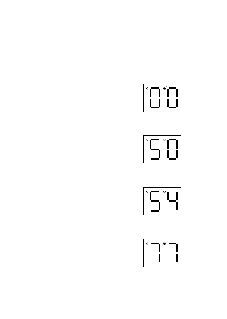
16.0 TROUBLESHOOTING
To aid in troubleshooting, Parameters 50 through 58 can be accessed without entering the PASSWORD.
Simply press the Mode button twice to “skip” over the PASSWORD prompt, and “50” will be
displayed to indicate that the parameter menu has been entered and Parameter 50 (FAULT HISTORY)
can be viewed. The s and t buttons can then be used to scroll from Parameter 50 to Parameter 58.
Once the desired parameter is found, press the Mode button to view its “contents”. When finished,
press Mode to exit the parameter menu. An example is shown below:
Press Mode once
Display reads "00"
Upper right decimal point blinks
Press Mode again
Display reads "50" (FAULT HISTORY)
Use s and t to scroll to the desired
parameter number
(In this example Parameter 54 has been
selected, which is MOTOR LOAD)
Press Mode to view parameter contents
(77 = 77% LOAD)
Upper right decimal point blinks
Press Mode again to exit
In the example above, Parameter 54 - MOTOR LOAD is being viewed. The “77” in the example
indicates that the load on the motor is 77% of the output current rating of the drive.
37
Page 42

The table below lists the fault conditions that will cause the drive to shut down, as well as some
possible causes. Please contact the factory for more information on troubleshooting faults.
FAU LT M ESSAGES
FAU LT
AF High Temperat ure F ault : Am bient t em perat ure is t oo high; Cooling fan has f ailed (if equipped).
CF Control F ault: A blank EPM, or an EPM wit h corrupt ed data has been inst alled. Perform a
fac t ory res e t us i ng Param et er 48 - PR OGR AM SELEC T I ON.
cF Inc om patibility F ault: An EPM w it h an inc om pat ible parameter v ers ion has been ins t alled.
Either remove t he EPM or perform a fac t ory res et (Param eter 48) to c hange the paramet er
version of t he EPM t o m atc h t he parameter v ersion of t he drive.
dF Dynamic Braking F ault: The driv e has s ensed t hat t he dynam ic braking resis tors are
overheating and shut s dow n to prot ect t he resist ors .
EF External Fault: One of t he TB-13 t erminals is s et as an Ext ernal Fault input and t hat t erm inal is
open with res pec t t o T B-11. R ef er t o Parameters 10, 11 and 12.
GF Data Fault : U s er dat a and OEM def ault s in t he EPM are c orrupted.
HF High DC Bus Volt age Fault : Line volt age is t oo high; Dec eleration rate is too f ast ; Overhauling
load. For f as t dec elerat ion or overhauling loads, dy nami c braking m ay be required.
JF Rem ot e Keypad Fault : T he com m unicat ion betw een the SC N driv e and the optional Rem ote
Keypad has been los t . C hec k f or proper w iring and/or noise.
LF Low DC Bus Voltage F ault : Line v olt age is too low.
OF Output Transis t or Fault : Phase t o phase or phase t o ground short c ircuit on the output ;
Boost s et t ings are t oo high; Ac c eleration rate is too fas t ; F ailed output t rans is t or.
PF Current Overload F ault: VF D is undersiz ed f or t he applicat ion; M ec hanic al problem w it h t he
driven equipment.
SF Single-phase Fault: Single-phase input power has been applied to a three-phase driv e.
UF Start F ault : Start c omm and was pres ent w hen the drive w as powered up. M ust w ait 2 s econds
after pow er-up t o apply St art c om m and if STAR T M ETHOD is s et t o N OR M AL.
F1 EPM Fault: T he EPM is mis s ing or damaged.
F2 - F9, Fo Internal Faults : The c ont rol board has s ens ed a problem - c onsult f actory .
DESCRIPTION & PO SSIBLE CAUSES
To clear a fault, issue a STOP command on the terminal strip. The fault will only clear if the condition
that caused the fault has passed. For example, if the drive trips on a LOW DC BUS VOLTAGE
FAULT (LF) due to low input voltage, the fault cannot be cleared until the input voltage returns to a
normal level.
If the drive is programmed to automatically restart after a fault (see Parameter 03), the drive will
attempt to restart three times after a fault (the drive will not restart after CF, cF, GF, F1, F2-F9, or Fo
faults). If all three restart attempts are unsuccessful, the drive will trip into FAULT LOCKOUT (LC),
which requires a manual reset as described above.
38
Page 43

17.0 SM-Basic DISPLAY MESSAGES
The following describes the various displays and messages that can appear on the SCN drive.
17.1 SPEED DISPLAY
If the drive is in a STOP state (indicated by "- -" on the display), and the keypad speed command is
changed, the display will show the commanded speed, and the upper left decimal point will turn on
solid. About five seconds after a change is made, the display will begin to alternate between the
commanded speed value and the "- -" display. If the Mode button is pressed, the display will stop
alternating and show the "- -" display only.
When the drive is given a START command, the displayed speed will start increasing as the drive
accelerates up to the commanded speed. If the keypad speed command is changed while the drive is
running, the display will show the commanded speed rather than the actual speed, until the actual
speed reaches the commanded speed.
If the keypad speed command is changed faster than the drive can accelerate or decelerate, the upper
left decimal point will blink to indicate that the the drive is accelerating or decelerating to the new
speed. Once the actual speed reaches the commanded speed, the upper left decimal point will turn on
solid for 5 seconds and then turn off to indicate that the commanded speed has been reached, and that
the display is now showing the actual speed.
17.2 CHANGING THE SPEED REFERENCE SOURCE
When the speed source is changed while the drive is running, the display will flash the message for
the new speed source to indicate that the new speed source is active. Also, if the drive is being
controlled from a speed source other than the s and t buttons (speed pot, preset speed, etc), and one
of the s or t buttons is pressed, the display will flash the present speed source message to indicate
that the s and t buttons are invalid.
Example 1: The drive is running and the present speed source is the keypad. TB-13A is programmed
to select a speed pot signal as the speed source. When TB-13A is closed to TB-11, the display will
flash “EU” to indicate that the speed source has changed to the speed pot signal. If the contact
between TB-13A and TB-11 is opened, the display will flash “CP” to indicate that the speed source
has changed back to the s and t buttons.
Example 2: The speed source is a speed pot. If the s or t button is pushed, the display will flash
“EU” to indicate that the present speed source is the speed pot and that the s and t buttons are
invalid.
Refer to the table below for the possible speed reference source displays:
39
Page 44

SPEED SOURCE DISPLAYS
SPEED SOURCE DISPLAYS
SPEED SOURCE DISPLAYSSPEED SOURCE DISPLAYS
DISPLAY
DISPLAY DESCRIPTION
DISPLAYDISPLAY
CP CONTROL PAD : Speed is s et us ing t he V and W buttons on t he f ront of t he driv e.
EU EXTERN AL VOLTAGE: Speed is c ont rolled by a s peed pot.
JG JOG: The driv e is in J og m ode, and t he speed is s et by Pres et Speed #2 (Paramet er 32).
OP MOP (Motor Operated Pot): Cont act s wired to t w o of t he TB-13 term inals are used to inc rease
and decrease t he drive s peed. See Paramet ers 10, 11, and 12.
P1 - P7 PRESET SPEEDS #1-7: Speed is s et by t he indic ated Pres et Speed (Parameters 31-37).
NOTE: The speed source displays will flash when the speed reference source is changed while the
drive is running to indicate that the new speed reference source is active.
17.3 STATUS AND WARNING MESSAGES
STATUS AND WARNING MESSAGES
STATUS AND WARNING MESSAGES
STATUS AND WARNING MESSAGESSTATUS AND WARNING MESSAGES
DISPLAY
DISPLAY DESCRIPTION
DISPLAYDISPLAY
br DC BRAKI N G: T he DC braking c ircuit is ac tiv at ed.
cE COMPATIBLE EPM: An EPM w ith a previous paramet er version has been inst alled, and an
attem pt was m ade to c hange the programm ing. T he drive will operate w ith t he EPM ins t alled,
but the param et ers c annot be c hanged. Refer t o s et t ing 06 (T R AN SLATE) in Param et er 48.
CL CURR EN T LI M I T : T he out put c urrent has ex c eeded t he C U R R EN T LI M I T s et t ing (Param eter 25)
and the drive is reducing t he output frequency t o reduce t he output current . I f the drive rem ains
in CUR R ENT LIM I T for t oo long, it c an trip into a CU R R ENT OVERLOAD fault (PF).
Er ERR OR : I nv alid data has been ent ered or an invalid c om m and w as at t em pt ed.
GE "GE" will be displayed if an at t em pt is m ade t o c hange t he OEM def ault s ettings w hen t he driv e is
operating in the OEM m ode (s ee Paramet er 48).
GF If "GF" is dis played w hen a RESET OEM is at t em pted, it indicat es that the OEM default s in t he
EPM are corrupted. If "GF " is display ed upon power-up, it indicat es that t he OEM default s and
the user s et t ings in t he EPM are c orrupted. R ef er t o Sec t ion 13. 2.
LC FAULT LOC KOUT : The driv e has f ailed t hree rest art at t em pt s and now requires a m anual reset .
SP START PEN D I N G: "SP" blink s during the int erv al betw een rest art at t em pt s .
DECEL OVER RI D E (both upper decim al points blinking): T he drive has s t opped decelerating t o
avoid tripping into an HF f ault due t o regenerativ e energy f rom t he m ot or.
DESCRIPTION
DESCRIPTIONDESCRIPTION
DESCRIPTION
DESCRIPTIONDESCRIPTION
40
Page 45

18.0 USER SETTING RECORD
NO.
NO. PARAMETER NAME
NO.NO.
01 LIN E VOLTAGE HIGH (01)
02 CARRIER FREQUENCY 6 kHz (02)
03 START MET H OD NORMAL (01)
04 STOP M ETH OD COAST (01)
05 STANDAR D SPEED SOU R CE KEYPAD (01)
06 TB-14 OUTPUT NONE (01)
10 TB-13A FU N C T I ON SELEC T NONE (01)
11 TB-13B FU N C T I ON SELEC T NONE (01)
12 TB-13C F U N C T I ON SELEC T NON E (01)
14 CONTROL TERMINAL STRIP ONLY (01)
17 ROTAT ION FORW AR D ONLY (01)
PARAMETER NAME FA CTORY DEFAULT
PARAMETER NAMEPARAMETER NAME
FACTORY DEFAULT USER SETTING
FACTORY DEFAULTFACTORY DEFAULT
USER SET T IN G
USER SET T IN GUSER SET T IN G
18 TIME RANGE SELECT x1.0 (02)
19 ACC ELERAT ION T IM E 20 SEC
20 DEC ELERAT I ON T IM E 20 SEC
21 DC BR AK E TI M E 0 SEC
22 D C BR AK E VOLT AGE 0 %
23 MINIMUM FREQUENCY 0 Hz
24 MAXIMUM FREQUENCY 60 Hz
41
Page 46

NO.
NO. PARAM ETER NAM E
NO.NO.
25 CURRENT LIMIT 180%
26 MOTOR OVERLOAD 100%
27 BASE FR EQU ENCY 60 H z
28 FI XED BOOST 1%
29 ACC EL BOOST 0%
30 SLIP COMPEN SATI ON 0%
31-37 PRESET SP EED S 0 Hz
38 SKIP BANDWIDTH 0 Hz
42 ACC EL / D EC EL #2 20 SEC
44 PASSWORD 25
47 CLEAR HISTOR Y MAI N TAI N (01)
48 PROGRAM SELECT I ON U SER SETT I N GS (01)
50 FAULT HISTORY (N/A)
PARAMETER NAME FA CTORY DEFAULT
PARAMETER NAMEPARAMETER NAME
FACTORY DEFAULT USER SETTING
FACTORY DEFAULTFACTORY DEFAULT
USER SETTING
USER SETTINGUSER SETTIN G
51 SOFTWARE CODE (N/A)
52 DC BUS VOLT AGE (N/A)
53 MOTOR VOLT AGE (N/A)
54 LOAD (N/A)
55 SPEED POT I N PU T (N/ A)
57 TB STR I P ST AT U S (N/ A)
58 KEYPAD S T ATUS (N/A)
42
Page 47

Service Dept. FAX (262)-377-0090
4/00
 Loading...