

Page 1

SPEEDMASTER
™
SCR THYRISTOR MOTOR CONTROLS
Catalog Numbers
174100, 174105, 174307, 174308, 174311, 174709,
M1740005, M1740006, M1740007
OPERATION MANUAL
Page 2

LIMITED WARRANTY
A. Warranty - Leeson Electric Corporation (referred to as “the Corporation”) warrants that its
products will be free from defects in material and workmanship for a period of one (1) year from
the date of shipment thereof. Within the warranty period, the Corporation will repair or replace such
products that are returned to Leeson Electric Corporation or to the nearest Branch Office, with
shipping charges prepaid. At our option, all return shipments are F.O.B. Leeson Electric or its
Branch Office. This warranty shall not apply to any product that has been subject to misuse,
negligence, or accident; or misapplied; or repaired by unauthorized persons; or improperly
installed. The Corporation is not responsible for removal, installation, or any other incidental
expenses incurred in shipping the product to or from the repair point.
B. Disclaimer - The provisions of Paragraph A are the Corporation’s sole obligation and exclude all
other warranties of MERCHANTABILITY or use, express or implied. The Corporation further
disclaims any responsibility whatsoever to the customer or any other persons for injury to person
or damage or loss of property of value caused by any product that has been subject to misuse,
negligence, or accident, or misapplied or modified by unauthorized persons or improperly installed.
C. Limitations of Liability - In the event of any claim or breach of any of the Corporation’s
obligations, whether expressed or implied, and particularly of any claim of a breach of warranty
claimed in Paragraph A, or of any other warranties, express, or implied, or claim of liability that
might, despite Paragraph B, be decided against us by any lawful authority, the Corporation shall
under no circumstances be liable for any consequential damages, losses, or expense arising in
connection with the use of, or inability to use, the Corporation’s product for any purpose
whatsoever. An adjustment made to the warranty does not void the warranty, nor does it imply an
extension of the original one (1) year warranty period. Product serviced and/or parts replaced by
a no-charge basis during the warranty period carry the unexpired portion of the original warranty
only.
If for any reason any of the forgoing provisions shall be ineffective, the Corporation’s liability for
damages arising out of its manufacture or sale if equipment, or use thereof, whether such liability
is based on warranty, contract, negligence, strict liability in tort, or otherwise, shall not in any event
exceed the full purchase of such equipment.
Any action against the Corporation based upon any liability or obligation arising hereunder or
under any law applicable to the sale of equipment or the use thereof must be commenced within
one year after the cause of such action arises.
Page 3

i
SPEEDMASTER™ OPERATION MANUAL
Safety Warnings
• This symbol denotes an important safety tip or
warning. Please read these instructions carefully before
performing any of the procedures contained in this manual.
• DO NOT INSTALL, REMOVE, OR REWIRE THIS
EQUIPMENT WITH POWER APPLIED. Have a qualified
electrical technician install, adjust and service this
equipment. Follow the National Electrical Code and all other
applicable electrical and safety codes, including the
provisions of the Occupational Safety and Health Act
(OSHA), when installing equipment.
• Reduce the chance of an electrical fire, shock, or explosion
by proper grounding, over-current protection, thermal
protection, and enclosure. Follow sound maintenance
procedures.
Warning
It is possible for a drive to run at full speed as a result
of a component failure. Leeson strongly recommends the
installation of a master switch in the main power input to
stop the drive in an emergency.
Circuit potentials are at 115 VAC or 230 VAC above earth
ground. Avoid direct contact with the printed circuit board or
with circuit elements to prevent the risk of serious injury or
fatality. Use a non-metallic screwdriver for adjusting the
calibration trimpots. Use insulated tools if working on this
drive with power applied.
SHOCKAVOID
OID
ON
TI
Page 4

Specifications 1
Dimensions 3
Installation 10
Chassis (uncased) drive installation . . . . . . . . . . . . . . . . . . . . . . . . . . . .10
Mounting . . . . . . . . . . . . . . . . . . . . . . . . . . . . . . . . . . . . . . . . . . . . . . .10
Wiring . . . . . . . . . . . . . . . . . . . . . . . . . . . . . . . . . . . . . . . . . . . . . . . . . .11
Shielding guidelines . . . . . . . . . . . . . . . . . . . . . . . . . . . . . . . . . . . . .12
Heat sinking . . . . . . . . . . . . . . . . . . . . . . . . . . . . . . . . . . . . . . . . . . . . .13
Line fusing . . . . . . . . . . . . . . . . . . . . . . . . . . . . . . . . . . . . . . . . . . . . . .13
Speed adjust potentiometer . . . . . . . . . . . . . . . . . . . . . . . . . . . . . . . . .15
Connections . . . . . . . . . . . . . . . . . . . . . . . . . . . . . . . . . . . . . . . . . . . . .16
Motor . . . . . . . . . . . . . . . . . . . . . . . . . . . . . . . . . . . . . . . . . . . . . . . .16
Power input . . . . . . . . . . . . . . . . . . . . . . . . . . . . . . . . . . . . . . . . . . .17
Line fuse . . . . . . . . . . . . . . . . . . . . . . . . . . . . . . . . . . . . . . . . . . . . .17
Voltage follower . . . . . . . . . . . . . . . . . . . . . . . . . . . . . . . . . . . . . . . . . .19
Cased drive installation . . . . . . . . . . . . . . . . . . . . . . . . . . . . . . . . . . . . . .20
Mounting (NEMA 1 enclosures) . . . . . . . . . . . . . . . . . . . . . . . . . . . . . .20
Mounting (NEMA 4 and NEMA 4/12 enclosures) . . . . . . . . . . . . . . . .21
Heat sinking . . . . . . . . . . . . . . . . . . . . . . . . . . . . . . . . . . . . . . . . . . . . .22
Line fusing . . . . . . . . . . . . . . . . . . . . . . . . . . . . . . . . . . . . . . . . . . . . . .23
Connections . . . . . . . . . . . . . . . . . . . . . . . . . . . . . . . . . . . . . . . . . . . . .23
Operation 25
Before applying power . . . . . . . . . . . . . . . . . . . . . . . . . . . . . . . . . . . . . . .25
Startup . . . . . . . . . . . . . . . . . . . . . . . . . . . . . . . . . . . . . . . . . . . . . . . . . . .26
174311 and M1740007 . . . . . . . . . . . . . . . . . . . . . . . . . . . . . . . . . . . .26
174100, 174307, 174709, and M1740005 . . . . . . . . . . . . . . . . . . . . . .26
174308 and M1740006 . . . . . . . . . . . . . . . . . . . . . . . . . . . . . . . . . . . .27
174105 . . . . . . . . . . . . . . . . . . . . . . . . . . . . . . . . . . . . . . . . . . . . . . . . .28
ii
SPEEDMASTER™ OPERATION MANUAL
Contents
Page 5

All drives . . . . . . . . . . . . . . . . . . . . . . . . . . . . . . . . . . . . . . . . . . . . . . .29
Starting and Stopping Methods . . . . . . . . . . . . . . . . . . . . . . . . . . . . . . . . .30
Line starting and line stopping . . . . . . . . . . . . . . . . . . . . . . . . . . . . . . .30
Inhibit circuit . . . . . . . . . . . . . . . . . . . . . . . . . . . . . . . . . . . . . . . . . . . . .31
Decelerating to minimum speed . . . . . . . . . . . . . . . . . . . . . . . . . . . . .32
Dynamic braking . . . . . . . . . . . . . . . . . . . . . . . . . . . . . . . . . . . . . . . . . .33
Sizing the dynamic brake resistor . . . . . . . . . . . . . . . . . . . . . . . . . .34
Calibration 35
Calibration procedure . . . . . . . . . . . . . . . . . . . . . . . . . . . . . . . . . . . . . . . .37
MINIMUM SPEED (MIN SPD) . . . . . . . . . . . . . . . . . . . . . . . . . . . . . .37
MAXIMUM SPEED (MAX SPD) . . . . . . . . . . . . . . . . . . . . . . . . . . . . . .38
REGULATION (IR COMP) . . . . . . . . . . . . . . . . . . . . . . . . . . . . . . . . .38
TORQUE LIMIT (TORQUE) . . . . . . . . . . . . . . . . . . . . . . . . . . . . . . . . .39
ACCELERATION (ACCEL ) . . . . . . . . . . . . . . . . . . . . . . . . . . . . . . . . .40
DECELERATION (DECEL) . . . . . . . . . . . . . . . . . . . . . . . . . . . . . . . . .40
Calibration procedure conclusion . . . . . . . . . . . . . . . . . . . . . . . . . . . .40
Application Notes 43
Multiple fixed speeds . . . . . . . . . . . . . . . . . . . . . . . . . . . . . . . . . . . . . . . .43
Adjustable speeds using potentiometers in series . . . . . . . . . . . . . . . . . .44
Independent adjustable speeds . . . . . . . . . . . . . . . . . . . . . . . . . . . . . . . .45
RUN/JOG switch . . . . . . . . . . . . . . . . . . . . . . . . . . . . . . . . . . . . . . . . . . .46
RUN/JOG option #1 . . . . . . . . . . . . . . . . . . . . . . . . . . . . . . . . . . . . . . .46
RUN/JOG option #2 . . . . . . . . . . . . . . . . . . . . . . . . . . . . . . . . . . . . . . .47
Reversing . . . . . . . . . . . . . . . . . . . . . . . . . . . . . . . . . . . . . . . . . . . . . . . . .48
Troubleshooting 49
Before troubleshooting . . . . . . . . . . . . . . . . . . . . . . . . . . . . . . . . . . . . . . .49
Current limit LED (174011 and M1740007) . . . . . . . . . . . . . . . . . . . . . . .50
iii
SPEEDMASTER™ OPERATION MANUAL
Contents
Page 6

Figure 1. 174311 and M1740007 Dimensions . . . . . . . . . . . . . . . . . . . . . . .3
Figure 2. 174307 and M1740005 Dimensions . . . . . . . . . . . . . . . . . . . . . . .4
Figure 3. 174308 and M1740006 Dimensions . . . . . . . . . . . . . . . . . . . . . . .5
Figure 4. 174100 Dimensions . . . . . . . . . . . . . . . . . . . . . . . . . . . . . . . . . . . .6
Figure 5. 174105 Dimensions . . . . . . . . . . . . . . . . . . . . . . . . . . . . . . . . . . . .7
Figure 6. 174709 Dimensions . . . . . . . . . . . . . . . . . . . . . . . . . . . . . . . . . . . .8
Figure 7. Heat Sink Dimensions . . . . . . . . . . . . . . . . . . . . . . . . . . . . . . . . . .9
Figure 8. Speed Adjust Potentiometer . . . . . . . . . . . . . . . . . . . . . . . . . . . .15
Figure 9. Chassis Drive Connections . . . . . . . . . . . . . . . . . . . . . . . . . . . . .18
Figure 10. Voltage Follower Connections . . . . . . . . . . . . . . . . . . . . . . . . . . .19
Figure 11. NEMA 1 Mounting Hole Locations . . . . . . . . . . . . . . . . . . . . . . . .21
Figure 12. Cased Drive Connections . . . . . . . . . . . . . . . . . . . . . . . . . . . . . .24
Figure 13. 174709 Connections . . . . . . . . . . . . . . . . . . . . . . . . . . . . . . . . . .24
Figure 14. Voltage Switches . . . . . . . . . . . . . . . . . . . . . . . . . . . . . . . . . . . . .25
Figure 15. Inhibit Plug with Run/Coast to Minimum Speed Switch . . . . . . . .31
Figure 16. Run/Decelerate to Minimum Speed Switch . . . . . . . . . . . . . . . . .32
Figure 17. Dynamic Brake Connection . . . . . . . . . . . . . . . . . . . . . . . . . . . . .33
Figure 18. Calibration Trimpot Layout . . . . . . . . . . . . . . . . . . . . . . . . . . . . . .36
Figure 19. Recommended TORQUE and IR COMP Settings . . . . . . . . . . .41
Figure 20. Recommended TORQUE and IR COMP Settings
for 174109 Series Controls . . . . . . . . . . . . . . . . . . . . . . . . . . . . .42
Figure 21. Multiple Fixed Speeds . . . . . . . . . . . . . . . . . . . . . . . . . . . . . . . . .43
Figure 22. Adjustable Fixed Speeds Using Potentiometers in Series . . . . .44
Figure 23. Independent Adjustable Speeds . . . . . . . . . . . . . . . . . . . . . . . . .45
Figure 24. RUN/JOG Switch Option #1 . . . . . . . . . . . . . . . . . . . . . . . . . . . .46
Figure 25. RUN/JOG Switch Option #2 . . . . . . . . . . . . . . . . . . . . . . . . . . . .47
Figure 26. Reversing Circuit Connection . . . . . . . . . . . . . . . . . . . . . . . . . . .48
Figure 27. Current Limit LED . . . . . . . . . . . . . . . . . . . . . . . . . . . . . . . . . . . .50
Tables
Table 1. Recommended Line Fuse Sizes . . . . . . . . . . . . . . . . . . . . . . . . . .14
Table 2. Field Output Connections . . . . . . . . . . . . . . . . . . . . . . . . . . . . . . .17
Table 3. Recommended Dynamic Brake Resistor Sizes . . . . . . . . . . . . . . .34
iv
SPEEDMASTER™ OPERATION MANUAL
Illustrations
Page 7

Max.
Armature HP Range HP Range
Current with 115 VAC with 230 VAC
Model (Amps DC) Applied Applied Style
M1740007 1.5 1/20–1/8 Chassis
M1740005 NEMA 1
M1740006 NEMA 4X
174311 † 5.0 1/8–1/2 1/4–1 Chassis
174307 ‡ NEMA 1
174308 ‡ NEMA 1
174100 10.0 1/8–1 1/4–2 NEMA 4X
174105 NEMA 4X
174709 15 1 – 1.5 2 – 3 NEMA 4X
† Double maximum armature current and horsepower when drive is mounted on
heat sink part number 174314.
‡ Double maximum armature current and horsepower when drive is mounted on
heat sink part number 174316.
AC Line Voltage 115 VAC or 230 VAC ±10%, 50/60 Hz, single phase
Armature Voltage
115 VAC Input 0–90 VDC
230 VAC Input 0–180 VDC
Field Voltage
115 VAC Input 50 VDC (F1 to L1); 100 VDC (F1 to F2)
230 VAC Input 100 VDC (F1 to L1); 200 VDC (F1 to F2)
Max. Field Current 1 ADC
Form Factor 1.37 at base speed
Accel. Time Range
0–90 VDC Armature Voltage 0.5–11 seconds
1
SPEEDMASTER™ OPERATION MANUAL
Specifications
Page 8

2
SPEEDMASTER™ OPERATION MANUAL
0–180 VDC Armature Voltage 0.5–22 seconds
Decel. Time Range
0-90 VDC Armature Voltage coast to a stop–13 seconds
0–180 VDC Armature Voltage coast to a stop–25 seconds
Analog Input Voltage Range (signal must be isolated; S1 to S2)
0–90 VDC Armature Voltage 0–1.4 VDC
0–180 VDC Armature Voltage 0–2.8 VDC
Input Impedance (S1 to S2) 100K ohms
Load Regulation 1% base speed or better
Vibration 0.5G max (0–50 Hz)
0.1G max (>50 Hz)
Safety Certification UL Recognized Component, file # E132235
CSA Certified Component, file # LR41380
CE Certificate of Compliance
Ambient Temp. Range
chassis drive 10°C–55°C
cased drive 10°C–40°C
Page 9
3
SPEEDMASTER™ OPERATION MANUAL
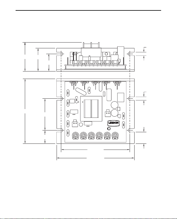
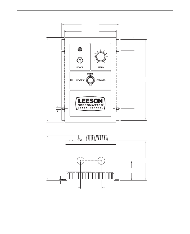
Dimensions
Figure 1. 174311 and M1740007 Dimensions
ALL DIMENSIONS IN INCHES [MILLIMETERS]
1.60 [41]
1.28 [33]
[24]
0.96
0.19 [5]
3.58 [91]
1.75 [44]
0.74 [19]
L1
F1
L2
S2
S3
MOV503
SW501
115 230
SO501
INHIBIT
D501SCR501
MO
V
50
F2
1
1
T501
C504
ACCEL DECEL
D502
A2
MOV502
R502
+
90
180
SW502
D503
SO502
-
+
METER
SPEEDMASTER
CL IL501
TORQUEMAXSPD MIN SPD
C503
C501
C502
IRCOMP
SCR502
R501
IC502
-
A1
IC501
S1
3.80 [97]
[109]
4.30
0.19 [5]
0.64 [16]
Page 10
4
Dimensions SPEEDMASTER™ OPERATION MANUAL
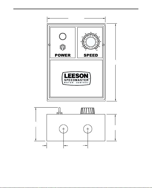
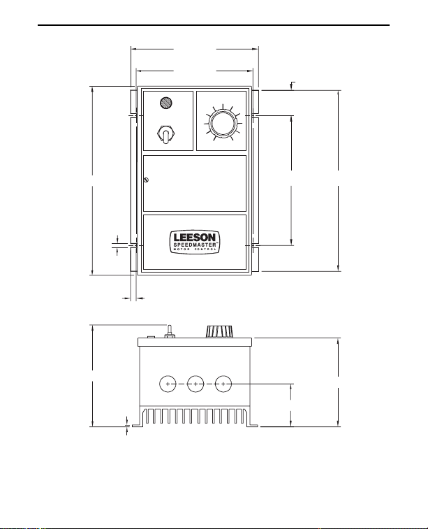
Figure 2. 174307 and M1740005 Dimensions
6.00 [152]
8.00 [203]
3.46 [88]
1.72 [44]
TWO 0.88 [22] CONDUIT HOLES
ALL DIMENSIONS IN INCHES [MILLIMETERS]
2.50 [64]
2.75 [70]
Page 11
5
Dimensions
SPEEDMASTER™ OPERATION MANUAL
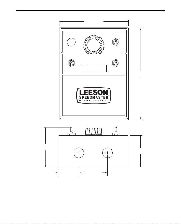
Figure 3. 174308 and M1740006 Dimensions
6.00 [152]
50
40
60
POWER
30
20
10
ALLOW MOTOR TO STOP
0
SPEED
WARNING!
BEFORE REVERSING
70
80
90
100
3.46 [88]
2.50
1.72 [44]
[64]
TWO 0.88 [22] CONDUIT HOLES
ALL DIMENSIONS IN INCHES [MILLIMETERS]
RUN
BRAKE
FORWARD
REVERSE
8.00 [203]
2.75 [70]
Page 12
6
Dimensions SPEEDMASTER™ OPERATION MANUAL
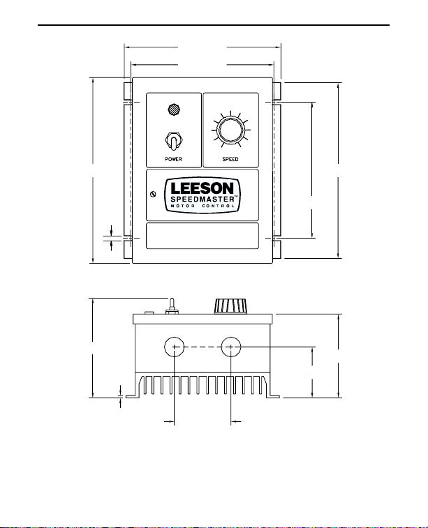
Figure 4. 174100 Dimensions
6.90 [175]
6.30 [160]
8.20 [208]
4.50 [1 14]
0.19
[5]
0.13
[3]
2.50 [64]
TWO 0.88 [22] KNOCKOUTS
ALL DIMENSIONS IN INCHES [MILLIMETERS]
6.00 [152]
2.25
7.78 [198]
3.70 [94]
[57]
Page 13
7
Dimensions
SPEEDMASTER™ OPERATION MANUAL
Figure 5. 174105 Dimensions
6.90 [175]
6.30 [160]
1.37 [35]
10.20 [259]
0.19
[5]
5.49 [139]
0.13
[3]
2.50
[64]
TWO 0.88 [22] KNOCKOUTS
ALL DIMENSIONS IN INCHES [MILLIMETERS]
9.76 [248]
7.00 [178]
4.78 [121]
2.37 [60]
Page 14
8
Dimensions SPEEDMASTER™ OPERATION MANUAL
Figure 6. 174709 Dimensions
6.90 [175]
6.30 [160]
POWER SPEED
1.39 [35]
10.20
5.50 [140]
[259]
0.19
[5]
0.30 [8]
THREE 0.88 [11] KNOCKOUTS
ON 1.50 [38] CENTERS
0.13
[3]
ALL DIMENSIONS IN INCHES [MILLIMETERS]
7.00 [178] 9.78 [248]
4.74 [120]
2.40 [60]
Page 15
9
Dimensions
SPEEDMASTER™ OPERATION MANUAL
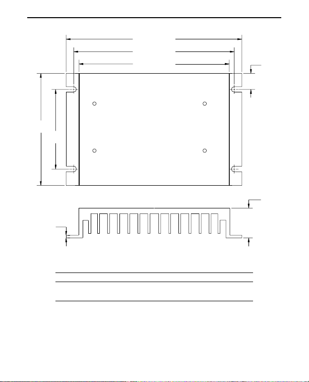
PART NO. DIM “A” DIM “B” DIM “C”
174314 4.40 [112] 3.00 [76] 0.7 [18]
174316 7.78 [198] 6.00 [152] 0.89 [23]
Heat sinks sold separately.
Figure 7. Heat Sink Dimensions
ALL DIMENSIONS IN INCHES [MILLIMETERS]
6.90 [175]
6.30 [160]
5.90 [150]
A
B
C
MOUNTING SLOTS 0.19 X .34 [5 X 9] 1.00
0.13
[3]
[25]
Page 16

10
SPEEDMASTER™ OPERATION MANUAL
Chassis (uncased) drive installation
Mounting
• Drive components are sensitive to electrostatic fields. Avoid
contact with the circuit board directly. Hold drive by the
chassis only.
• Protect the drive from dirt, moisture, and accidental contact.
• Provide sufficient room for access to the terminal block and
calibration trimpots.
• Mount the drive away from other heat sources. Operate the
drive within the specified ambient operating temperature
range.
• Prevent loose connections by avoiding excessive vibration
of the drive.
• Mount drive with its board in either a horizontal or vertical
plane. Six 0.19 in. (5 mm) wide slots in the chassis accept
#8 pan head screws. Fasten either the large base or the
narrow flange of the chassis to the subplate.
• The chassis does not have to be earth grounded. If you
choose to ground the chassis, use a star washer beneath
the head of at least one of the mounting screws to
penetrate the anodized chassis surface and to reach bare
metal.
Installation
Page 17

11
Installation
SPEEDMASTER™ OPERATION MANUAL
• Use 16–20 AWG wire for speed adjust potentiometer wiring.
Use 14–16 AWG wire for AC line (L1, L2) and motor (A1
and A2) wiring.
Warning
Do not install, remove, or rewire this equipment with power
applied. Failure to heed this warning may result in fire,
explosion, or serious injury.
Circuit potentials are at 115 VAC or 230 VAC above ground.
To prevent the risk of injury or fatality, avoid direct contact
with the printed circuit board or with circuit elements.
Do not disconnect any of the motor leads from the drive
unless power is removed or the drive is disabled. Opening
any one motor lead may destroy the drive.
Ꮨ
Wiring
Page 18

12
Installation SPEEDMASTER™ OPERATION MANUAL
Shielding guidelines
Warning
Under no circumstances should power and logic leads be
bundled together. Induced voltage can cause unpredictable
behavior in any electronic device, including motor controls.
As a general rule, Leeson recommends shielding of all
conductors.
If it is not practical to shield power conductors, Leeson
recommends shielding all logic-level leads. If shielding logic
leads is not practical, the user should twist all logic leads with
themselves to minimize induced noise.
It may be necessary to earth ground the shielded cable. If noise
is produced by devices other than the drive, ground the shield at
the drive end. If noise is generated by a device on the drive,
ground the shield at the end away from the drive. Do not ground
both ends of the shield.
If the drive continues to pick up noise after grounding the shield,
it may be necessary to add AC line filtering devices, or to mount
the drive in a less noisy environment.
Logic wires from other input devices, such as motion controllers
and PLL velocity controllers, must be separated from power lines
in the same manner as the logic I/O on this drive.
Page 19

13
Installation
SPEEDMASTER™ OPERATION MANUAL
Heat sinking
Model 174311 requires an additional heat sink when the
continuous armature current is above 5 ADC. Use Leeson part
number 174314. Use a thermally conductive heat sink
compound between the drive chassis and heat sink surface for
optimum heat transfer.
No additional heat sinking is required for Model M1740007.
Line fusing
The National Electric Code requires the installation of a circuit
breaker or fuse on the incoming AC line voltage. When the AC
line voltage is 115 VAC, fuse the hot leg of the AC line that
connects to L1 and leave L2 unfused. When the AC line voltage
is 230 VAC, fuse both L1 and L2. Use a circuit breaker or fuse
that is rated approximately 150% of the maximum motor
armature current. See Table 1 (page 14) for recommended line
fuse sizes.
Page 20

14
Installation SPEEDMASTER™ OPERATION MANUAL
Table 1. Recommended Line Fuse Sizes
FUSE SIZE (AMPS) FUSE SIZE
(AMPS)
MOTOR HP @ 115 VAC INPUT @ 230 VAC INPUT
1/4 5 3
1/3 8 3
1/2 8 5
3/4 10 8
115 8
1 1/2 – 10
2– 15
3– 30
Page 21

15
Installation
SPEEDMASTER™ OPERATION MANUAL
JUST
R
SK
R
R
UT
E
Figure 8. Speed Adjust Potentiometer
On chassis drives, install the circular insulating disk between
the panel and the 10K ohm speed adjust potentiometer. Mount
the speed adjust potentiometer through a 0.38 in. (10 mm) hole
with the hardware provided (Figure 8). Twist the speed adjust
potentiometer wire to avoid picking up unwanted electrical noise.
If potentiometer leads are longer than 18 in. (457 mm), use
shielded cable.
All cased drives come with the speed adjust potentiometer
installed.
Speed adjust potentiometer
Warning
Be sure that the potentiometer tabs do not make contact
with the potentiometer enclosure. Grounding the input will
cause damage to the drive.
UNT THROUGH A 0.38 IN. (10 MM) HOL
W
N
TA
WASHE
INSULATING DI
PEED AD
POTENTIOMETE
Page 22

16
Installation SPEEDMASTER™ OPERATION MANUAL
Warning
Do not connect this equipment with power applied.
Failure to heed this directive may result in fire or serious
injury.
Leeson strongly recommends the installation of a
master power switch in the voltage input line, as shown
in Figure 9 (page 18). The switch contacts should be rated
at a minimum of 200% of motor nameplate current and 250
volts.
Connect the power input leads, an external line fuse and a DC
motor to TB501 on the drive’s printed circuit board (PCB) as
shown in Figure 9, page 18.
Motor
Leeson drives supply motor voltage from A1 and A2 terminals. It
is assumed throughout this manual that, when A1 is positive with
respect to A2 , the motor will rotate clockwise (CW) while
looking at the output shaft protruding from the front of the motor.
If this is opposite of the desired rotation, simply reverse the
wiring of A1 and A2 with each other.
Connect a DC motor to PCB terminals A1 and A2 as shown in
Figure 9. Ensure that the motor voltage rating is consistent with
the drive’s output voltage.
Connections
Page 23

17
Installation
SPEEDMASTER™ OPERATION MANUAL
Power input
Connect the AC line power leads to PCB terminals L1 and L2, or
to a single-throw, double-pole master power switch
(recommended). The switch should be rated at a minimum of
250 volts and 200% of motor current.
Line fuse
Wire an external line fuse between the stop switch (if installed)
and the L1 terminal on the PCB. An additional line fuse should
be installed on L2 if the input voltage is 230VAC. The line
fuse(s) should be rated at 250 volts and 150 - 200% of
maximum motor nameplate current. Refer to the line fuse chart
on page 14 for fuse ratings.
See Table 2 for field output connections. Use 18 AWG wire to
connect the field output to a shunt wound motor.
Table 2. Field Output Connections
Line Voltage Approximate Connect Motor
(VAC) Field Voltage (VDC) Field To
115 50 F1 and L1
115 100 F1 and F2
230 100 F1 and L1
230 200 F1 and F2
Warning
The field output is for shunt wound motors only. Do not
make any connections to F1 and F2 when using a
permanent magnet motor.
Page 24

NOTE: DO NOT ADD LINE FUSE TO L2 UNLESS LINE VOLTAGE IS 230
VAC.
18
Installation SPEEDMASTER™ OPERATION MANUAL
Figure 9. Chassis Drive Connections
NOTE: DO NOT make
FIELD COILS
(See Table 2 for connections)
any connections to
F1 & F2 terminals if
using a permanent
magnet motor.
LINE
FUSE
FUSE
(see notes)
D502
D501SCR501
F2
MOV501
T501
A2
A2
1
F2
C504
+
90 180
SW502
L1
L1
F1
F1
MOV503
SW501
L2
L2
115 230
S2
S2
SO501
INHIBIT
S3
MOV502
R502
SO502
+
METER
CL IL501
D503
C503
C501
-
C502
SPEEDMASTER
SCR502
R501
IC502
A1
A1
IC501
S1
S1
S3
STOP
SWITCH
ACCEL DECEL MAX SPD MIN SPD TORQUE IR COMP
CW
115/230 VAC
LINE VOLTAGE
10K OHMS
SPEED ADJUST
POTENTIOMETER
MOTOR
+
Page 25

19
Installation
SPEEDMASTER™ OPERATION MANUAL
Figure 10. Voltage Follower Connections
Voltage follower
Instead of using a speed adjust potentiometer, the drive may be
wired to follow a voltage signal that is isolated from earth ground
(Figure 10). Connect the signal input (+) to S2. Connect the
signal common (–) to S1. Make no connection to S3. A
potentiometer can be used to scale the analog input voltage.
For 90 VDC motors, the voltage range is 0 - 1.4 VDC. For 180
VDC motors, the voltage range is 0 - 2.8 VDC.
LEESON
SPEEDMASTER™
Signal Input
Signal Common
+
-
DRIVE
S2
S1
Page 26

20
Installation SPEEDMASTER™ OPERATION MANUAL
Cased drive installation
Mounting (NEMA 1 enclosures)
NEMA 1 cased drives come with 0.88 inch (22 mm) conduit
holes at the bottom of the case. The units may be vertically wall
mounted or horizontally bench mounted using the three keyholes
on the back of the case (see Figure 11). To mount the drive:
1. For access to the keyholes and the terminal strip, remove
the two screws from the front of the case by turning them
counterclockwise. Grasp the front cover and lift it straight
out.
2. Install the mounting screws in the three keyholes.
3. Install conduit hardware through the conduit holes at the
bottom of the case. Connect external wiring to the terminal
block.
4. Reinstall the front cover. Avoid pinching any wires between
the front cover and the case.
5. Replace the two screws to the front cover. Turn the screws
clockwise to tighten.
6. Set the POWER switch to the OFF position before applying
the AC line voltage.
Page 27

21
Installation
SPEEDMASTER™ OPERATION MANUAL
Mounting (NEMA 4 and NEMA 4/12 enclosures)
NEMA 4/12 cased drives (models 174100 and 174105) come
with two 0.88 inch (22 mm) conduit knockout holes at the bottom
of the case. Model 174709, a NEMA 4 cased drive, comes with
three knockout holes at the bottom of the case. All NEMA 4 and
NEMA 4/12 drives may be vertically wall mounted using the four
0.19 inch (5 mm) slotted holes on the attached heat sink. For
motor loads less than 5 ADC, the drive may be bench mounted
horizontally, or operated without mounting.
Figure 11. NEMA 1 Mounting Hole Locations
6.00 [152]
1.79 [45.0]
2.50 [64]
C
L
2.50 [64]
5.00 [127]
8.00 [203]
Page 28

22
Installation SPEEDMASTER™ OPERATION MANUAL
To mount the drive:
1. Install the mounting screws.
2. For access to the terminal strip, turn the slotted screw on
the front cover counterclockwise until it is free from the
case. The right side of the cover is hinged to the case. Pull
the slotted screw to open the case.
3. Carefully remove the conduit knockouts by tapping them
into the case and twisting them off with pliers.
4. Install conduit hardware through the 0.88 inch (22 mm)
knockout holes. Connect external wiring to the terminal
block.
5. Grasp the slotted screw and tilt the front cover back into
place. Avoid pinching any wires between the front cover
and the case.
6. Turn the slotted screw clockwise until tight to secure the
front cover.
7. Set the POWER switch to the OFF position before applying
the AC line voltage.
Heat sinking
Models 174307 and 174308 require an additional heat sink,
Leeson part number 174316, when the continuous armature
current is above 5 ADC. Use a thermally conductive heat sink
compound between the back of the drive case and heat sink
surface for optimum heat transfer.
All other cased drives do not require additional heat sinking to
operate up their rated output current.
Page 29

23
Installation
SPEEDMASTER™ OPERATION MANUAL
Warning
Do not connect this equipment with power applied.
Failure to heed this directive may result in fire or serious
injury.
For all Leeson cased controls except the 174709 series, connect
the power input leads and a DC motor to the drive’s terminal
block as shown in Figure 12 (page 24). If you use a Leeson
174709 series cased control, connect the control as shown in
Figure 13 (page 24).
Line fusing
Line fuses are preinstalled on all cased drives. Models 174307,
174308, 174100, and 174105 have 15A line fuses; model
174709 has 30A line fuses; and models M1740005 and
M1740006 have 3A line fuses. If the horsepower rating of the
motor being used is less than the maximum horsepower rating of
the drive, the line fuse may have to be replaced with a lower
rated one. Refer to Table 1 on page 14 for recommended line
fuse sizes.
Connections
Page 30

24
Installation SPEEDMASTER™ OPERATION MANUAL
Figure 13. 174709 Connections
Figure 12. Cased Drive Connections
D
)
5
C
30
C
OR
E
:
.
.
OTO
D
)
e
NOTE: If using a shunt
wound motor with 174709
refer to Table 2 for field
connections.
11
EARTH GROUN
GREEN SCREW
VA
2
VA
NOTE: DO NOT mak
any connections to
terminal 7 if using a
permanent magnet motor.
MOT
ARMATUR
WITH 115 VAC INPUT
NNECT TO TERMINAL 1 FOR 50 VOLT FIELD
NNECT TO TERMINAL 6 FOR 100 VOLT FIELD
WITH 230 VAC INPUT:
CONNECT TO TERMINAL 1 FOR 100 VOLT FIELD.
CONNECT TO TERMINAL 6 FOR 200 VOLT FIELD.
R FIELD
M
SHUNT WOUN
MOTORS ONLY
A2A1
EARTH GROUND
(GREEN SCREW)
115 VAC
230 VAC
115 OR 230
VAC LINE
VOLTAGE INPUTS
MOTOR
ARMATURE
Page 31

25
SPEEDMASTER™ OPERATION MANUAL
Before applying power
• Set voltage switch SW501 to either 115 or 230 to match the
AC line voltage. Set voltage switch SW502 to either 90 or 180
to match the maximum armature voltage (see Figure 14).
• Verify that no conductive material is present on the printed
circuit board.
• If using a 90 VDC or 130 VDC motor with 230 VAC line
voltage, derate the nameplate motor speed and torque by at
least 30%.
MOV503
Figure 14. Voltage Switches
Warning
Change voltage switch settings only when the drive is
disconnected from AC line voltage. Make sure both
switches are set to their correct position. If the switches are
improperly set to a lower voltage position, the motor will not
run at full voltage. If the switches are improperly set to a
higher voltage position, the motor will overspeed, which
may cause motor damage.
Operation
T501
SW501
L2
L2
VOLTAGE
SWITCHES
115 230
S2
C504
SO501
INHIBIT
+
180
90
SW502
S2
S3
SO502
+
METER
CL IL501
-
C502
SPEEDMASTER
IC502
A1
A1
IC501
S1
S1
Page 32

26
Operation SPEEDMASTER™ OPERATION MANUAL
Startup
174311 and M1740007
1. Turn the speed adjust potentiometer full counterclockwise
(CCW).
2. Apply AC line voltage.
3. Slowly advance the speed adjust potentiometer clockwise
(CW). The motor slowly accelerates as the potentiometer is
turned CW. Continue until the desired speed is reached.
4. Remove AC line voltage from the drive to coast the motor to
a stop.
174100, 174307, 174709, and M1740005
1. Set the speed adjust potentiometer to “0” (full CCW).
2. Apply AC line voltage.
3. Set the POWER switch to the ON position.
4. Slowly advance the speed adjust potentiometer CW. The
motor slowly accelerates as the potentiometer is turned
CW. Continue until the desired speed is reached.
5. Set the POWER switch to the OFF position to coast the
motor to a stop.
Page 33

27
Operation
SPEEDMASTER™ OPERATION MANUAL
1. Set the RUN/BRAKE switch to the BRAKE position.
2. Set the speed adjust potentiometer to “0” (full CCW).
3. Apply AC line voltage.
4. Set the POWER switch to the ON position.
5. Set the FORWARD/REVERSE switch to the desired
direction of rotation.
6. Set the RUN/BRAKE switch to the RUN position.
7. Slowly advance the speed adjust potentiometer CW. The
motor slowly accelerates as the potentiometer is turned
CW. Continue until the desired speed is reached.
8. To brake the motor, set the RUN/BRAKE switch to the
BRAKE position. To coast the motor to a stop, set the
POWER switch to the OFF position.
9. To reverse direction:
a. Set the RUN/BRAKE switch to the BRAKE position.
b. Set the FORWARD/REVERSE switch to the desired
direction of rotation.
c. Set the RUN/BRAKE switch to the RUN position.
174308 and M1740006
Warning
Do not change the FORWARD/ REVERSE switch while the
motor is running. The motor must come to a complete stop
before reversing. Changing motor direction before allowing
the motor to completely stop will cause excessively high
current to flow in the armature circuit, and may damage the
drive and/or motor.
Page 34

28
Operation SPEEDMASTER™ OPERATION MANUAL
1. Set the FORWARD/BRAKE/REVERSE switch to the
BRAKE position.
2. Set the speed adjust potentiometer to “0” (full CCW).
3. Apply AC line voltage.
4. Set the POWER switch to the ON position.
5. Set the FORWARD/BRAKE/REVERSE switch to the
desired direction of rotation.
6. Slowly advance the speed adjust potentiometer CW. The
motor slowly accelerates as the potentiometer is turned
CW. Continue until the desired speed is reached.
7. To brake the motor, set the FORWARD/BRAKE/REVERSE
switch to the BRAKE position. To coast the motor to a stop,
set the POWER switch to the OFF position.
8. To reverse direction:
a. Set the FORWARD/BRAKE/REVERSE switch to the
BRAKE position.
b. After the motor comes to a complete stop, set the
FORWARD/BRAKE/REVERSE switch to the desired
direction of rotation.
174105
Warning
Do not change the FORWARD/ REVERSE switch while the
motor is running. The motor must come to a complete stop
before reversing. Changing motor direction before allowing
the motor to completely stop will cause excessively high
current to flow in the armature circuit, and may damage the
drive and/or motor.
Page 35

29
Operation
SPEEDMASTER™ OPERATION MANUAL
All drives
If the motor or drive does not perform as described, disconnect
the AC line voltage immediately. Refer to Troubleshooting,
page 49, for further assistance.
Page 36

30
Operation SPEEDMASTER™ OPERATION MANUAL
Line starting and line stopping
Line stopping (removing AC line voltage) is recommended for
infrequent stopping of a drive only. When AC line voltage is
applied to the drive, the motor accelerates to the speed set by
the speed adjust potentiometer. When AC line voltage is
removed, the motor coasts to a stop.
Warning
Decelerating to minimum speed, dynamic braking, inhibit
operation, or coasting to a stop (shorting S1 to S2) is
recommended for frequent starts and stops. Do not use any
of these methods for emergency stopping. They may not
stop a drive that is malfunctioning. Removing AC line power
(both L1 and L2) is the only acceptable method for
emergency stopping.
Starting and Stopping Methods
Page 37

31
Operation
SPEEDMASTER™ OPERATION MANUAL
Inhibit circuit
Maintaining a connection between the inhibit pins causes the
motor to coast to minimum speed. Removing the connection
between the inhibit pins allows the motor to accelerate to the
speed set by the speed adjust potentiometer (Figure 15).
Figure 15. Inhibit Plug with Run/Coast to
Minimum Speed Switch
SO501
RUN
INHIBIT
PINS
COAST TO
MINIMUM SPEED
Page 38

32
Operation SPEEDMASTER™ OPERATION MANUAL
Figure 16. Run/Decelerate to Minimum Speed Switch
Decelerating to minimum speed
The circuit shown in Figure 16 may be used to decelerate a
motor to a minimum speed. Closing the switch between S1 and
S2 decelerates the motor from set speed to a minimum speed
determined by the MIN SPD trimpot setting. If the MIN SPD
trimpot is set full CCW, the motor decelerates to zero speed
when the switch between S1 and S2 is closed. The DECEL
trimpot setting determines the rate at which the drive
decelerates. By opening the switch, the motor accelerates to
set speed at a rate determined by the ACCEL trimpot setting.
S3
S2
S1
RUN
DECEL TO
MIN SPEED
CW
10K OHM
SPEED ADJUST
POTENTIOMETER
Page 39

33
Operation
SPEEDMASTER™ OPERATION MANUAL
Dynamic braking may be used to rapidly stop a motor
(Figure 17). For the RUN/BRAKE switch, use a double pole,
double throw switch rated for at least the maximum DC armature
voltage and maximum braking current.
Dynamic braking
Figure 17. Dynamic Brake Connection
Warning
Wait for the motor to completely stop before switching it
back to RUN. This will prevent high armature currents from
damaging the motor or drive.
A2A1
RUN
BRAKE
INHIBIT
DYNAMIC BRAKE
RESISTOR
MOTOR
Page 40

34
Operation SPEEDMASTER™ OPERATION MANUAL
Sizing the dynamic brake resistor
Size the dynamic brake resistor according to the motor current
rating (Table 3). The dynamic brake resistance listed in the table
is the smallest recommended resistance allowed to prevent
possible demagnetization of the motor. The motor stops less
rapidly with higher brake resistor values.
Table 3. Recommended Dynamic Brake Resistor
Sizes
Minimum Minimum
Motor Armature Dynamic Brake Dynamic Brake
Current Rating Resistor Value Resistor
Wattage
Less than 2 ADC 1 ohm 1W
2–3 ADC 5 ohm 5W
3–5 ADC 10 ohm 10W
5–10 ADC 20 ohm 20W
10–17 ADC 40 ohm 50W
For motors rated 1/17 horsepower and lower, a brake resistor is
not necessary since the armature resistance is high enough to
stop the motor without demagnetization. Replace the dynamic
brake with 12 gauge wire.
NOTE: Models 174105, 174308 and M1740006 are factoryequipped with dynamic braking.
Page 41

35
SPEEDMASTER™ OPERATION MANUAL
Calibration
Warning
Dangerous voltages exist on the drive when it is powered.
When possible, disconnect the voltage input from the drive
before adjusting the trimpots. If the trimpots must be
adjusted with power applied, use insulated tools and the
appropriate personal protection equipment. BE ALERT.
High voltages can cause serious or fatal injury.
Each drive is factory calibrated to its maximum current rating.
Readjust the calibration trimpot settings to accommodate lower
current rated motors.
All adjustments increase with CW rotation, and decrease with
CCW rotation. Use a non-metallic screwdriver for calibration.
Each trimpot is identified on the printed circuit board. Refer to
Figures 18 and 19 (pages 41-42) for typical TORQUE LIMIT and
IR COMP settings.
Page 42

36
Calibration SPEEDMASTER™ OPERATION MANUAL
Figure 18. Calibration Trimpot Layout
L1
F1
L2
S2
S3
ACCELERATION
DECELERATION
L1
F1
L2
S2
S3
MOV503
SW501
115 230
SO501
INHIBIT
ACCEL
F2
D501SCR501
MOV501
T501
MAXIMUM SPEED
D502
A2
1
F2
C504
+
90 180
SW502
DECEL MAX SPD MIN SPD TORQUE IR COMP
A2
MOV502
R502
+
METER
CL IL501
MINIMUM SPEED
D503
SO502
-
SPEEDMASTER
C501
C502
C503
R501
-
IC501
TORQUE
SCR502
IC502
A1
A1
S1
S1
REGULATION
(IR COMPENSATION)
Page 43

37
Calibration
SPEEDMASTER™ OPERATION MANUAL
Calibration procedure
Calibrate the drive using the following procedure:
1. Set the MIN SPD, MAX SPD, ACCEL and DECEL trimpots
to zero (full CCW).
2. Set the TORQUE trimpot to maximum (full CW).
3. Set the IR COMP trimpot to midrange (approximate 12
o’clock position).
4. Set the signal input (analog voltage signal or speed adjust
potentiometer) to zero.
5. Apply power to the drive.
6. Calibrate the trimpots as follows:
MINIMUM SPEED (MIN SPD)
The MIN SPD setting determines the motor speed when the
speed adjust potentiometer is turned full CCW. It is factory set to
zero speed.
To calibrate, turn the speed adjust potentiometer full CCW.
Adjust the MIN SPD trimpot until the motor has stopped, or is
running at the desired minimum speed.
Page 44

38
Calibration SPEEDMASTER™ OPERATION MANUAL
MAXIMUM SPEED (MAX SPD)
The MAX SPD setting determines the motor speed when the
speed adjust potentiometer is turned full CW. It is factory set for
maximum rated speed.
To calibrate, set the MAX SPD trimpot full CCW. Turn the speed
adjust potentiometer full CW. Adjust the MAX SPD trimpot until
the desired maximum motor speed is reached.
Note: Check the MIN SPD and MAX SPD adjustments after
recalibrating to verify that the motor runs at the desired minimum
and maximum speed.
REGULATION (IR COMP)
The IR COMP setting determines the degree to which motor
speed is held constant as the motor load changes. It is factory
set for optimum motor regulation.
Recalibrate the IR COMP setting when using a lower
horsepower motor. Refer to the recommended IR COMP settings
on page 41 and 42, or recalibrate using the following procedure:
If the motor does not maintain set speed as the load changes,
gradually rotate the IR COMP trimpot CW. If the motor oscillates
(overcompensation), the IR COMP trimpot may be set too high.
Turn the IR COMP trimpot CCW to stabilize the drive.
Page 45

39
Calibration
SPEEDMASTER™ OPERATION MANUAL
TORQUE LIMIT (TORQUE)
The TORQUE setting determines the maximum torque for
accelerating and driving the motor. TORQUE is factory set at
120% of maximum drive current. You must recalibrate the
TORQUE setting if using a lower current rated motor. See
Figure 19 (page 41) and Figure 20 (page 42) for typical
TORQUE and IR COMP settings.
1. With no power applied to the drive, connect a DC ammeter
in series with the motor armature.
2. Set the TORQUE trimpot to full CCW.
3. Carefully lock the motor armature. Ensure that the motor
is firmly mounted.
4. Apply line power. The motor should be stopped.
5. Set the speed potentiometer or reference signal to
maximum speed. The motor should remain stopped.
6. Slowly rotate the TORQUE trimpot clockwise (CW) until
the ammeter reads 120% of maximum motor armature
current.
7. Set the speed adjust potentiometer or reference signal to
zero speed.
Warning
Although TORQUE is set to 120% of drive nameplate
current rating, continuous operation beyond that rating may
damage the motor. If you intend to operate beyond the
rating, contact your Leeson representative for assistance.
Page 46

40
Calibration SPEEDMASTER™ OPERATION MANUAL
8. Remove power from the drive.
9. Remove the lock from the motor shaft.
10. Remove the ammeter in series with the motor armature.
ACCELERATION (ACCEL )
The ACCEL setting determines the time the motor takes to to
ramp to a higher speed. See Specifications on page 1 for
approximate acceleration times. The ACCEL setting is factory set
to its minimum value (full CCW).
Turn the ACCEL trimpot CW to increase the acceleration time,
and CCW to decrease the acceleration time.
DECELERATION (DECEL)
The DECEL setting determines the time the motor takes to ramp
to a lower speed. See Specifications on page 1 for approximate
deceleration times. The DECEL setting is factory set to its
minimum value (full CCW).
Turn the DECEL trimpot CW to increase the deceleration time,
and CCW to decrease the deceleration time.
Calibration procedure conclusion
This concludes the calibration procedure. The control should
now be calibrated for optimum operation.
Page 47

41
Calibration
SPEEDMASTER™ OPERATION MANUAL
Figure 19. Recommended TORQUE and IR COMP Settings
Models M1740005, M1740006, and M1740007
Models 174100, 174105, 174307, 174308, and 174311
TORQUE IR COMP
TORQUE IR COMP
1/8 HP
90 VDC
1800 RPM
1.3 AMPS
1/15 HP
90 VDC
1800 RPM
0.77 AMPS
TORQUE IR COMP
TORQUE IR COMP
1/4 HP
180 VDC
1800 RPM
1.4 AMPS
1/8 HP
180 VDC
1800 RPM
0.67 AMPS
TORQUE
TORQUE
TORQUE
TORQUE
TORQUE
IR COMP
IR COMP
IR COMP
IR COMP
IR COMP
1
90
1750
10
3/4
90
1750
7.6
1/2
90
1750
5.0
1/3
90
1750
3.5
1/4
90
1750
2.7
HP
VDC
RPM
AMPS
HP
VDC
RPM
AMPS
HP
VDC
RPM
AMPS
HP
VDC
RPM
AMPS
HP
VDC
RPM
AMPS
TORQUE
TORQUE
TORQUE
TORQUE
TORQUE
IR COMP
IR COMP
IR COMP
IR COMP
IR COMP
2
180
1750
9.2
1 1/2
180
1750
7.0
1
180
1750
5.0
3/4
180
1750
3.8
1
180
1750
1.3
HP
VDC
RPM
AMPS
HP
VDC
RPM
AMPS
HP
VDC
RPM
AMPS
HP
VDC
RPM
AMPS
/2
HP
VDC
RPM
AMPS
Page 48

42
Calibration SPEEDMASTER™ OPERATION MANUAL
Model 174109
Figure 20. Recommended TORQUE
and IR COMP Settings for 174109 Series Controls
TORQUE
TORQUE
TORQUE
TORQUE
IR COMP
IR COMP
IR COMP
IR COMP
1
90
1750
10
3/4
90
1750
7.5
1/2
90
1750
5.0
1/4
90
1750
2.5
HP
VDC
RPM
AMPS
HP
VDC
RPM
AMPS
HP
VDC
RPM
AMPS
HP
VDC
RPM
AMPS
TORQUE
TORQUE
TORQUE
TORQUE
TORQUE
IR COMP
IR COMP
IR COMP
IR COMP
IR COMP
3
180
1750
14
2
180
1750
10.0
1 1/2
180
1750
7.5
1
180
1750
5.0
1
180
1750
2.5
/2
HP
VDC
RPM
AMPS
HP
VDC
RPM
AMPS
HP
VDC
RPM
AMPS
HP
VDC
RPM
AMPS
HP
VDC
RPM
AMPS
Page 49

43
SPEEDMASTER™ OPERATION MANUAL
Multiple fixed speeds
Replace the speed adjust potentiometer with series resistors
with a total series resistance of 10K ohms (Figure 21). Add a
single pole, multi-position switch with the correct number of
positions for the desired number of fixed speeds.
S
CE
S
Figure 21. Multiple Fixed Speeds
Application Notes
TOTAL SERIE
ESISTAN
10K OHM
Page 50

44
Application Notes SPEEDMASTER™ OPERATION MANUAL
Adjustable speeds using potentiometers in
series
Replace the speed adjust potentiometer with a single pole,
multi-position switch, and two or more potentiometers in series,
with a total series resistance of 10K ohms. Figure 22 shows a
connection for fixed high and low speed adjust potentiometers.
2
K
M
K
M
H
D
W
D
Figure 22. Adjustable Fixed Speeds Using
Potentiometers in Series
HIG
SPEE
S
LO
PEE
5
H
5
OH
Page 51

45
Application Notes
SPEEDMASTER™ OPERATION MANUAL
Independent adjustable speeds
Replace the speed adjust potentiometer with a single pole, multiposition switch, and two or more potentiometers in parallel, with
a total parallel resistance of 10K ohms. Figure 23 shows the
connection of two independent speed adjust potentiometers that
can be mounted at two separate operating stations.
1
2
0K
0K
M
Figure 23. Independent Adjustable Speeds
PEED
PEED
2
HM
2
H
Page 52

46
Application Notes SPEEDMASTER™ OPERATION MANUAL
RUN/JOG switch
Using a RUN/JOG switch is recommended in applications where
quick stopping is not needed and frequent jogging is required.
Use a single pole, two position switch for the RUN/JOG switch,
and a single pole, normally closed, momentary operated
pushbutton for the JOG pushbutton.
RUN/JOG option #1
In the first wiring option, connect the RUN/JOG switch and JOG
pushbutton to the inhibit plug as shown in Figure 24. The motor
coasts to a stop when the RUN/JOG switch is set to JOG. Press
the JOG pushbutton to jog the motor. Return the RUN/JOG
switch to RUN for normal operation.
Figure 24. RUN/JOG Switch Option #1
JOG
RUN
PUSHBUTTON
INHIBIT
JOG
Page 53

47
Application Notes
SPEEDMASTER™ OPERATION MANUAL
RUN/JOG option #2
In the second wiring option, connect the RUN/JOG switch and
the JOG pushbutton as shown in the Figure 25. When the
RUN/JOG switch is set to JOG, the motor decelerates to
minimum speed (minimum speed is determined by the MIN SPD
trimpot setting). Press the JOG pushbutton to jog the motor.
Return the RUN/JOG switch to RUN for normal operation.
M
JUST
R
UN
ON
Figure 25. RUN/JOG Switch Option #2
PEED AD
POTENTIOMETE
R
PUSHBUTT
10K OH
Page 54

48
Application Notes SPEEDMASTER™ OPERATION MANUAL
Reversing
A dynamic brake may be used when reversing the motor
direction (Figure 26). Use a three pole, three position switch
rated for at least the maximum DC armature voltage and
maximum braking current. When in the brake position, wait for
the motor to stop completely before switching it to either the
forward or reverse direction. See the Dynamic braking section,
page 32, for sizing the dynamic brake resistor.
Note: Model 174709 is equipped with this reversing feature.
Figure 26. Reversing Circuit Connection
A1 A2
DYNAMIC
BRAKE
RESISTOR
MOTOR
INHIBIT
FWD
BRAKE
REV
Page 55

49
SPEEDMASTER™ OPERATION MANUAL
Warning
Dangerous voltages exist on the drive when it is powered.
When possible, disconnect the drive while troubleshooting.
High voltages can cause serious or fatal injury.
Before troubleshooting
Perform the following steps before starting any procedure in this
section:
• Disconnect AC line voltage from the drive.
• Check the drive closely for damaged components.
• Check that no conductive or other foreign material has
become lodged on the printed circuit board.
• Verify that every connection is correct and in good
condition.
• Verify that there are no short circuits or grounded
connections.
• Check that the voltage switch settings match the AC line
and maximum armature output voltages.
• Check that the drive’s rated armature outputs are consistent
with the motor ratings.
Troubleshooting
Page 56

50
Troubleshooting SPEEDMASTER™ OPERATION MANUAL
Current limit LED (174011 and M1740007)
174011 and M1740007 series drives are equipped with a red,
PCB-mounted current limit LED. The red current limit LED turns
on whenever the drive reaches current limit and turns off
whenever the drive is not in current limit (normal operation).
Figure 27. Current Limit LED
MOV503
T501
L2
S2
S3
SW501
L2
115 230
S2
S3
C504
SO501
INHIBIT
+
90
180
SW502
ACCEL DECEL MAX SPD MIN SPD TORQUE IR COMP
CURRENT LIMIT
LED
SO502
-
+
METER
SPEEDMASTER
CL IL501
C502
IC501
IC502
A1
A1
S1
S1
Page 57

51
Troubleshooting
SPEEDMASTER™ OPERATION MANUAL
Symptom Possible
Causes
Suggested
Solutions
Fuse blows or circuit
breaker trips
Line fuse does not
blow or circuit breaker
does not trip, but the
motor does not run
1. Line fuses or circuit
breakers are the wrong
size.
2. Motor cable or armature
is shorted to ground.
3. Nuisance tripping caused
by a combination of
ambient conditions and
high-current spikes.
1. Reference signal or
speed adjust pot is set to
zero speed.
2. Reference signal or
speed adjust
potentiometer
connections are open.
1. Check that line fuses or
circuit breakers are the
proper size.
2. Check motor cable and
armature for shorts.
3. Add a blower to cool
the drive components;
decrease TORQUE
settings, or resize
motor and drive for
actual load demand, or
check for incorrectly
aligned mechanical
components or “jams”.
See page 39 for
information on
adjusting the TORQUE
trimpot.
1. Increase reference
signal or speed adjust
potentiometer setting.
2. Check that the
reference signal or
speed adjust
potentiometer
connections are not
open.
Page 58

52
Troubleshooting SPEEDMASTER™ OPERATION MANUAL
Symptom Possible
Causes
Suggested
Solutions
Line fuse does not
blow or circuit breaker
does not trip, but the
motor does not run
(cont.)
Motor runs too fast at
maximum speed
setting
Motor runs too slow or
too fast
Motor will not reach
the desired speed.
3. Drive is in current limit.
4. Drive is not receiving
AC line voltage.
5. Motor is not connected.
1. MIN SPD and MAX
SPD settings are too
high.
MIN SPD and MAX SPD
are not calibrated.
1. MAX SPD setting is too
low.
2. IR COMP setting is too
low.
3. Motor is overloaded.
3. Verify that the motor is
not jammed. Increase
TORQUE setting (page
39).
4. Apply AC line voltage
to L1 and L2.
5. Connect motor to A1
and A2.
1. Recalibrate MIN SPD
(page 37) and MAX
SPD (page 38).
1. Recalibrate MIN SPD
(page 37) and MAX
SPD (page 38).
1. Increase MAX SPD
setting (page 38).
2. Increase IR COMP
setting (page 38).
3. Check motor load.
Resize the motor or
drive if necessary.
Page 59

53
Troubleshooting
SPEEDMASTER™ OPERATION MANUAL
Symptom Possible
Causes
Suggested
Solutions
Motor pulsates or
surges under load
On non-reversing
drives, motor runs in
the opposite direction
Motor will not stop
when the speed adjust
potentiometer or
reference signal is set
to zero speed.
1. IR COMP is set too high.
2. Control is in current
limit mode.
1. Motor armature leads
are reversed.
1. MIN SPD trimpot is not
adjusted properly.
1. Adjust the IR COMP
setting slightly CCW
until the motor speed
stabilizes (page 38).
2. Check that motor is of
sufficient horsepower
and amperage.
1. Reverse connections to
the motor armature.
1. Slowly rotate the MIN
SPD trimpot until the
motor stops.
Page 60

54
SPEEDMASTER™ OPERATION MANUAL
DISCLAIMER
The information and technical data in this manual are subject to
change without notice. LEESON Electric Corporation makes no
warranty of any kind with regard to this material, including, but
not limited to, the implied warranties of merchantability and
fitness for a particular purpose. LEESON Electric Corporation
assumes no responsibility for any errors that may appear in this
manual and makes no commitment to update or to keep current
the information in this manual.
LEESON ELECTRIC CORPORATION
GRAFTON, WI 53024-0241 U.S.A. TELEPHONE (262) 377-8810 FAX (262) 377-9025
PRINTED IN U.S.A.
DOCUMENT NO. 250–0218, Revision 6
2/05
 Loading...