

Page 1

Operation Manual
SPEEDMASTER
174102, 174103 & 174107
NEMA 4X SCR MOTOR CONTROLS
®
®
Page 2

LIMITED WARRANTY
A. Warranty - LEESON Electric warrants that its products will be free from defects in
material and workmanship for a period of one (1) year from the date of shipment
thereof. Within the warranty period, LEESON will repair or replace such products that
are returned to LEESON or to the nearest Branch Office, with shipping charges
prepaid. At our option, all return shipments are F.O.B. LEESON or its Branch Office.
This warranty shall not apply to any product that has been subject to misuse,
negligence, or accident; or misapplied; or repaired by unauthorized persons; or
improperly installed. LEESON is not responsible for removal, installation, or any other
incidental expenses incurred in shipping the product to or from the repair point.
B. Disclaimer - The provisions of Paragraph A are LEESON’s sole obligation and
exclude all other warranties of MERCHANTABILITY or use, express or implied.
LEESON further disclaims any responsibility whatsoever to the customer or any other
persons for injury to person or damage or loss of property of value caused by any
product that has been subject to misuse, negligence, or accident, or misapplied or
modified by unauthorized persons or improperly installed.
C. Limitations of Liability - In the event of any claim or breach of any of LEESON’s
obligations, whether expressed or implied, and particularly of any claim of a breach of
warranty claimed in Paragraph A, or of any other warranties, express, or implied, or
claim of liability that might, despite Paragraph B, be decided against us by any lawful
authority, LEESON shall under no circumstances be liable for any consequential
damages, losses, or expense arising in connection with the use of, or inability to use,
LEESON’s product for any purpose whatsoever. An adjustment made to the warranty
does not void the warranty, nor does it imply an extension of the original one (1) year
warranty period. Product serviced and/or parts replaced by a no-charge basis during
the warranty period carry the unexpired portion of the original warranty only.
If for any reason any of the forgoing provisions shall be ineffective, LEESON’s liability
for damages arising out of its manufacture or sale if equipment, or use thereof, whether
such liability is based on warranty, contract, negligence, strict liability in tort, or
otherwise, shall not in any event exceed the full purchase of such equipment.
Any action against LEESON based upon any liability or obligation arising hereunder or
under any law applicable to the sale of equipment or the use thereof must be
commenced within one year after the cause of such action arises.
Page 3

SPEEDMASTER™ OPERATION MANUAL
SHOCKAVOID
OID
ON
i
Safety Warnings
• This symbol denotes an important safety tip or
warning. Please read these instructions carefully before
performing any of the procedures contained in this manual.
• DO NOTINSTALL, REMOVE, OR REWIRETHIS
EQUIPMENT WITH POWER APPLIED. Have a qualified
electrical technician install, adjust and service this
equipment. Follow the National Electrical Code and all other
applicable electrical and safety codes, including the
provisions of the Occupational Safety and Health Act
(OSHA), when installing equipment.
• Reduce the chance of an electrical fire, shock, or explosion
by proper grounding, over-current protection, thermal
protection, and enclosure. Follow sound maintenance
procedures.
Warning
It is possible for a drive to run at full speed as a result
of a component failure. LEESON strongly recommends
the installation of a master switch in the main power input
to stop the drive in an emergency.
Circuit potentials are at 115 VAC or 230 VAC above earth
ground. Avoid direct contact with the printed circuit board
or with circuit elements to prevent the risk of serious injury
or fatality. Use a non-metallic screwdriver for adjusting the
calibration trimpots. Use insulated tools if working on this
drive with power applied.
TI
Page 4

ii
SPEEDMASTER™ OPERATION MANUAL
Contents
Warranty Statement Inside Front Cover
Safety Warnings i
Specifications 1
Dimensions 2
Overview 3
Installation 4
Mounting . . . . . . . . . . . . . . . . . . . . . . . . . . . . . . . . . . . . . . . . . . . . . . . .4
Removing the Plastic Cover . . . . . . . . . . . . . . . . . . . . . . . . . . . . . . . . . .4
Line fusing . . . . . . . . . . . . . . . . . . . . . . . . . . . . . . . . . . . . . . . . . . . . . . .4
Connections . . . . . . . . . . . . . . . . . . . . . . . . . . . . . . . . . . . . . . . . . . . . . .5
Field Output . . . . . . . . . . . . . . . . . . . . . . . . . . . . . . . . . . . . . . . . . . . . . .9
Voltage Switches . . . . . . . . . . . . . . . . . . . . . . . . . . . . . . . . . . . . . . . . . .9
Calibration 10
Calibration procedure . . . . . . . . . . . . . . . . . . . . . . . . . . . . . . . . . . . . . . . .12
MINIMUM SPEED (MIN SPD) . . . . . . . . . . . . . . . . . . . . . . . . . . . . . .12
MAXIMUM SPEED (MAX SPD) . . . . . . . . . . . . . . . . . . . . . . . . . . . . . .13
REGULATION (IR COMP) . . . . . . . . . . . . . . . . . . . . . . . . . . . . . . . . .13
TORQUE LIMIT (TORQUE) . . . . . . . . . . . . . . . . . . . . . . . . . . . . . . . . .14
ACCELERATION (ACCEL) . . . . . . . . . . . . . . . . . . . . . . . . . . . . . . . . .15
DECELERATION (DECEL) . . . . . . . . . . . . . . . . . . . . . . . . . . . . . . . . .15
Calibration procedure conclusion . . . . . . . . . . . . . . . . . . . . . . . . . . . .15
Operation 17
Before applying power . . . . . . . . . . . . . . . . . . . . . . . . . . . . . . . . . . . . . . .17
Startup . . . . . . . . . . . . . . . . . . . . . . . . . . . . . . . . . . . . . . . . . . . . . . . . . . . .18
174102 . . . . . . . . . . . . . . . . . . . . . . . . . . . . . . . . . . . . . . . . . . . . . . . . .18
Page 5

SPEEDMASTER™ OPERATION MANUAL
174103 . . . . . . . . . . . . . . . . . . . . . . . . . . . . . . . . . . . . . . . . . . . . . . . . .19
174107 . . . . . . . . . . . . . . . . . . . . . . . . . . . . . . . . . . . . . . . . . . . . . . . . .20
Application Notes 21
Inhibit circuit . . . . . . . . . . . . . . . . . . . . . . . . . . . . . . . . . . . . . . . . . . . . . . .21
Decelerating to minimum speed . . . . . . . . . . . . . . . . . . . . . . . . . . . . . . . .23
Dynamic Braking . . . . . . . . . . . . . . . . . . . . . . . . . . . . . . . . . . . . . . . . . . . .24
Multiple Fixed Speeds . . . . . . . . . . . . . . . . . . . . . . . . . . . . . . . . . . . . . . .26
Adjustable speeds using potentiometers in series . . . . . . . . . . . . . . . . . .27
Independent adjustable speeds . . . . . . . . . . . . . . . . . . . . . . . . . . . . . . . .28
RUN/JOG switch . . . . . . . . . . . . . . . . . . . . . . . . . . . . . . . . . . . . . . . . . . .29
RUN/JOG option #1 . . . . . . . . . . . . . . . . . . . . . . . . . . . . . . . . . . . . . . .29
RUN/JOG option #2 . . . . . . . . . . . . . . . . . . . . . . . . . . . . . . . . . . . . . . .30
Leader-follower application . . . . . . . . . . . . . . . . . . . . . . . . . . . . . . . . . . . .31
Single speed potentiometer control of multiple drives . . . . . . . . . . . . . . .32
Reversing . . . . . . . . . . . . . . . . . . . . . . . . . . . . . . . . . . . . . . . . . . . . . . . . .33
Troubleshooting 34
Before troubleshooting . . . . . . . . . . . . . . . . . . . . . . . . . . . . . . . . . . . . . . .34
Power and Current Limit LEDs . . . . . . . . . . . . . . . . . . . . . . . . . . . . . . . . .35
Troubleshooting Tables . . . . . . . . . . . . . . . . . . . . . . . . . . . . . . . . . . . . . . .36
Replacement Parts . . . . . . . . . . . . . . . . . . . . . . . . . . . . . . . . . . . . . . . . . .39
Contents
iii
Page 6

iv
SPEEDMASTER™ OPERATION MANUAL
Illustrations
Figure 1. 174102, 174103 & 174107 Dimensional Diagrams . . . . . . . . . . . . .2
Figure 2. Cover removal for terminal strip access . . . . . . . . . . . . . . . . . . . . .6
Figure 3. Drive connections . . . . . . . . . . . . . . . . . . . . . . . . . . . . . . . . . . . . . .7
Figure 3a. External Signal Connections, 174103.00 . . . . . . . . . . . . . . . . . . .8
Figure 4. Voltage Switches . . . . . . . . . . . . . . . . . . . . . . . . . . . . . . . . . . . . . . .9
Figure 5. Calibration Trimpot Layout . . . . . . . . . . . . . . . . . . . . . . . . . . . . . . .11
Figure 6. Recommended TORQUE and IR COMP Settings . . . . . . . . . . . .16
Figure 7. Inhibit Plug with Run/Coast to Minimum Speed . . . . . . . . . . . . . .22
Figure 8. Run/Decelerate to Minimum Speed Switch . . . . . . . . . . . . . . . . . .23
Figure 9. Dynamic Brake Connection . . . . . . . . . . . . . . . . . . . . . . . . . . . . . .25
Figure 10. Multiple Fixed Speeds . . . . . . . . . . . . . . . . . . . . . . . . . . . . . . . . .26
Figure 11. Adjustable Fixed Speeds Using Potentiometers in Series . . . . . .27
Figure 12. Independent Adjustable Speeds . . . . . . . . . . . . . . . . . . . . . . . . .28
Figure 13. RUN/JOG Switch Option #1 . . . . . . . . . . . . . . . . . . . . . . . . . . . .29
Figure 14. RUN/JOG Switch Option #2 Connection to
Figure 15. Leader-Follower Application . . . . . . . . . . . . . . . . . . . . . . . . . . . .31
Figure 16. Single Speed Potentiometer Control of Multiple Drives . . . . . . .32
Figure 17. Reversing Circuit Connection . . . . . . . . . . . . . . . . . . . . . . . . . . .33
Figure 18. Current Limit LED . . . . . . . . . . . . . . . . . . . . . . . . . . . . . . . . . . . .35
Speed Adjust Potentiometer . . . . . . . . . . . . . . . . . . . . . . . . . . . .30
Tables
Table 1. Recommended Line Fuse Sizes . . . . . . . . . . . . . . . . . . . . . . . . . . .5
Table 2. Field Output Connections . . . . . . . . . . . . . . . . . . . . . . . . . . . . . . . . .9
Table 3. Replacement Parts . . . . . . . . . . . . . . . . . . . . . . . . . . . . . . . . . . . . .39
Page 7

SPEEDMASTER™ OPERATION MANUAL
1
Specifications
Max.
Armature HP Range HP Range
Model (Amps DC) Applied Applied Style
174102 10.0 1/8–1 1/4–2 NEMA 4X
174103 10.0 1/8–1 1/4–2 NEMA 4X
174107 10.0 1/8–1 1/4–2 NEMA 4X
AC Line Voltage 115 VAC or 230 VAC ±10%, 50/60 Hz, single phase
Armature Voltage (115 VAC Input) 0–90 VDC
Armature Voltage (230 VAC Input) 0–180 VDC
Form Factor 1.37 at base speed
Field Voltage (115 VAC Input) 50 VDC (F1 to L1); 100 VDC (F1 to F2)
Field Voltage (230 VAC Input) 100 VDC (F1 to L1); 200 VDC (F1 to F2)
Max. Field Current 1 ADC
Accel. Time Range:
for 0–90 VDC Armature Voltage 1 – 15 seconds
for 0–180 VDC Armature Voltage 1 – 15 seconds
**Analog Input Voltage Range (signal must be isolated; S1 to S2):
for 0–90 VDC Armature Voltage 0 – 1.4 VDC
for 0–180 VDC Armature Voltage 0 – 2.8 VDC
Decel. Time Range:
for 0-90 VDC Armature Voltage 1 – 15 seconds
for 0–180 VDC Armature Voltage 1 – 15 seconds
Current Limit Range:
for 0–90 VDC Armature Voltage 0 – 14 A
for 0–180 VDC Armature Voltage 0 – 13.5 A
Input Impedance (S1 to S2) 3M ohms
Load Regulation 1% base speed or better
Vibration 1G max (0–50 Hz)
Ambient Temp. Range (cased drive) 10°C–40°C
**Does not Apply to 174103
Current with 115 VAC with 230 VAC
Page 8
2
]
]
]
S
S
E
D
F
0
]
0
]
]
S
S
]
]
]
]
]
0
1
5
8
9
1
0
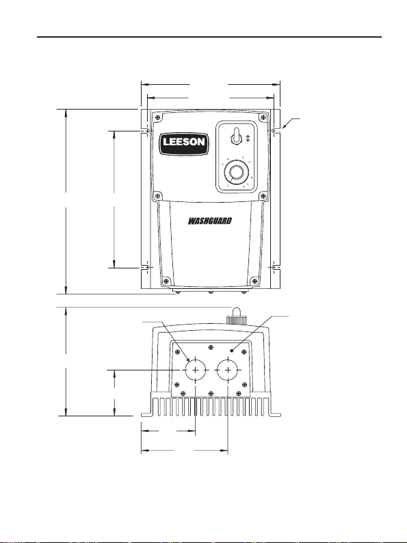
Dimensions
SPEEDMASTER™ OPERATION MANUAL
5.63[143
5.16[ 131
POWER
SPEEDMASTER
®
F
2
0.19[5.00
LOTTED HOLE
4 PLACE
.50[191
5.50[140
0.73[18.5
NDUIT HOLE
2 PLACE
ADJUSTABLE SPEED
DC MOTOR CONTROL
PEE
®
OTTOM PLAT
4.56[116
2.12[53.8
2.2
55.9
.4
86.4
ALL DIMENSIONS IN INCHES [MILLIMETERS
Figure 1. 174102, 174103 & 174107 Dimensional Diagrams
Page 9

SPEEDMASTER™ OPERATION MANUAL
Overview
The following is a quick-step guide to setting up the control. For
more detailed installation information, read the Installation (page
4) and Calibration (page 10) sections of this user ’s manual.
1. Mount the control using the 4 slotted holes on the heat sink.
The slotted holes are 0.19 inches [5 mm] (see Figure 1).
2. Remove the plastic cover by unscrewing the 6 screws on the
front cover and 5 screws on the bottom plate. NOTE: Do not
remove the 3 screws securing the bottom plate to the
heatsink.
3. Change the line fuse if necessary. If the horsepower rating
of the motor being used is less than the maximum HP rating
of the drive, the line fuse may have to be replace with a lower
rated one.
3. Wire the control through the conduit holes, or optional
aluminum hardware. NOTE: Do not connect the control
while power is applied.
4. Assure that settings on voltage switches are correct (SW501
& SW502).
5. Apply power to the drive.
3
5. Calibrate the trimmer pots, if neccessary.
6. Re-install the plastic cover.
Page 10

4
SPEEDMASTER™ OPERATION MANUAL
Installation
Mounting
174102, 174103 and 174107 drives may be vertically wall
mounted using the four 0.19 inch (5 mm) slotted holes on the
attached heat sink (see Figure 1, Page 2). For motor loads less
than 5 ADC, the drive may be bench mounted horizontally, or
operated without mounting.
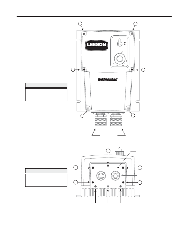
Removing the Plastic Cover
Connections, calibration, and other settings must be made
internally. After mounting, use the following procedure to remove
the plastic cover and configure the control:
1. Remove the six (6) phillips screws on the front cover. NOTE:
The two shorter screws (#6 - 32 x 2 ½) are for the two lower
holes on the front of the cover (see Figure 2, page 6).
2. Remove the five (5) phillips screws on the bottom plate (see
Figure 2, page 6). NOTE: DO NOT remove the 3 screws
securing the bottom plate to the heatsink.
Line fusing
Line fuses are preinstalled on all 174102, 174103 and 174107
drives. If the horsepower rating of the motor being used is less
than the maximum horsepower rating of the drive, the line fuse
may have to be replaced with a lower rated one. Refer to Table 1
for recommended line fuse sizes.
Page 11

SPEEDMASTER™ OPERATION MANUAL
Table 1. Recommended Line Fuse Sizes
FUSE SIZE (AMPS) FUSE SIZE (AMPS)
MOTOR HP @ 115 VAC INPUT @ 230 VAC INPUT
1/4 5 3
1/3 8 3
1/2 8 5
3/4 10 8
115 8
1 1/2 – 10
2– 15
Installation
Connections
Warning
Do not connect this equipment with power applied.
Failure to heed this directive may result in fire or serious
injury.
1. Install conduit hardware through the two 0.73” (18.5 mm)
conduit holes or by using aluminum cord connectors attached
to the line seal plate on the bottom of the case.
5
2. Connect external wiring to the terminal block as shown in
Figure 3, page 7.
Page 12
6
R
D
F
0
1
2
5
9
1
0
Installation
SPEEDMASTER™ OPERATION MANUAL
1
2
POWE
F
7
4
8
3
PEE
®
S T E P # 1
REMOVE THE SIX (6)
PHILLIPS SCREWS ON
THE FRONT CASE.
NOTE: THE TWO SHORTER
SCREWS (#6 - 32 x 2 ½) ON
THE FRONT CASE ARE USED
AT HOLE LOCATIONS 5 & 6.
SPEEDMASTER
3
5
®
ADJUSTABLE SPEED
DC MOTOR CONTROL
CUSTOMER
SUPPLIED
WATERTIGHT CORD
CONNECTORS (2)
1
S T E P # 2
REMOVE THE FIVE (5)
PHILLIPS SCREWS ON
THE BOTTOM PLATE.
2
4
DO NOT REMOVE
THE THREE (3) SCREWS SECURING
THE BOTTOM PLATE TO THE HEATSINK
Figure 2. Cover removal for terminal strip access
4
6
BOTTOM PLATE
3
CUSTOMER SUPPLIED
WATERTIGHT CORD
CONNECTORS (2)
5
Page 13
SPEEDMASTER™ OPERATION MANUAL
O
Installation
7
MOV501
MOV503
F1
M
F502
F501
TB501
F2
L2-115
L2-230
230 VAC
115 VAC
EARTH GROUND
(GREEN SCREW)
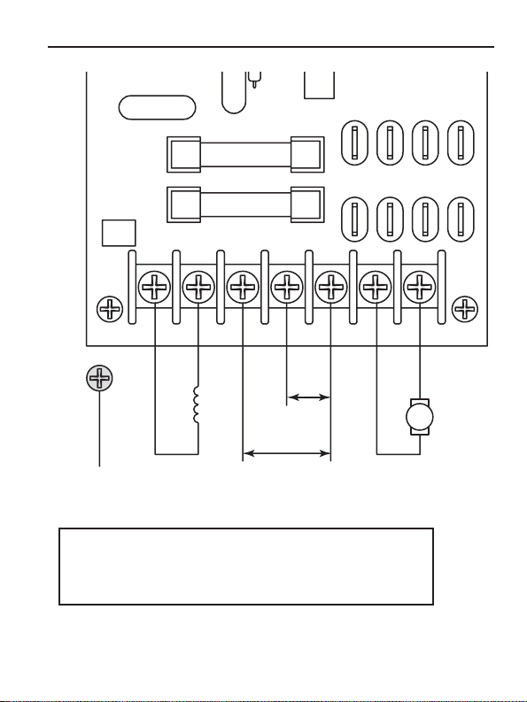
The field output is for shunt wound motors only. Do not make any
connections to F1 and F2 when using a permanent magnet motor.
FIELD
OUTPUT
FIELD OUTPUT CONNECTIONS
For field motor connections, see Table 2 on Page 9.
LINE VOLTAGE INPUT
(115 or 230 VAC)
L2 FRM SW L1
L2 TO SW L1
L1
A2 FRM SW A1
A2
MOTOR
ARMATURE
A2 TO SW A1
A1
+
Figure 3. Drive connections
Page 14
8
Installation SPEEDMASTER™ OPERATION MANUAL
IC1
3
2
1
SO501
R9
R7
R8
C4
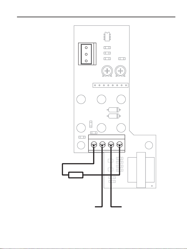
SIG MAXSIG MIN.
PL501
TQ LIMIT
IR COMP MIN. SPD MAX SPD
R6
RSH
RSH = 1000 OHM for 4 - 20 mA
RSH = 250 OHM for 10 - 50 mA
RSH = NOT USED for 1 - 5 mA
RSH = NOT USED for 0 - 10V signal
TERMINAL 2
+ 0 - 10V
SPEED ADJUST
SIGNAL INPUT
P502 P501
ACCEL
D501
D502
C3
R5
123 4
Q2
C2
R2
Q1
DECEL
R1
C1
R3
R4
TERMINAL 3
(-) COMMON
TB501
T501
Figure 3a. External Signal Connections
For 174103.00 Only
PCM CARD
Page 15
SPEEDMASTER™ OPERATION MANUAL
Installation
Field Output
The field output is for shunt wound motors only. Do not make
any connections to F1 and F2 when using a permanent magnet
motor. Use 18 AWG wire to connect the field output to a shunt
wound motor. Table 2 lists the field output connections.
Table 2. Field Output Connections
Line Voltage Approx. Field Connect Motor
(VAC) Voltage (VDC) Field To
115 50 F1 and L1
115 100 F1 and F2
230 100 F1 and L1
230 200 F1 and F2
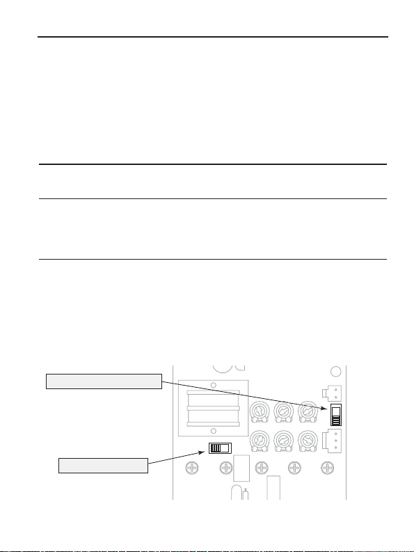
Voltage Switches
• Set voltage switch SW501 to either 115 or 230 to match the
AC line voltage (see Figure 4 below).
• Set voltage switch SW502 to either 90 or 180 to match the
maximum armature voltage (see Figure 4 below).
SW501
230 - 115
IC502C501
SO501
TQ LIMIT
R501
IR COMP
R502
V502
DECEL
ACCEL
MAX SPD
MIN SPD
C503
SO502
MAX ARMATURE VOLTAGE SWITCH
SW502 (90 or 180 VDC)
T501
AC LINE VOLTAGE SWITCH
SW501 (115 or 230 VAC)
Figure 4. Voltage Switches
9
C504
INHIBIT
SW502180 - 90
S3 S2 S1
Page 16

10
SPEEDMASTER™ OPERATION MANUAL
Calibration
Warning
Dangerous voltages exist on the drive when it is powered.
When possible, disconnect the voltage input from the drive
before adjusting the trimpots. If the trimpots must be
adjusted with power applied, use insulated tools and the
appropriate personal protection equipment. BE ALERT.
High voltages can cause serious or fatal injury.
All drives have six user-adjustable trimpots: Torque Limit
(TORQUE), Acceleration (ACCEL), Deceleration (DECEL),
Regulation (IR COMP), Minimum Speed (MIN SPD), and
Maximum Speed (MAX SPD). Each drive is factory calibrated to
its maximum current rating. Readjust the calibration trimpot
settings to accommodate lower current rated motors.
All adjustments increase with CW rotation, and decrease with
CCW rotation. Use a non-metallic screwdriver for calibration.
Each trimpot is identified on the printed circuit board. Refer to
Figure 5 (page 11) for trimpot locations and Figure 6 (page 16)
for typical TORQUE LIMIT and IR COMP settings.
Page 17

SPEEDMASTER™ OPERATION MANUAL Calibration
1
501
501
502
1
1
S
50
C501
C50
502
501
T
501
L
T
L
11
I
I
R
F
F
TB
IL
WER
2
ACCE
TQ LIMI
DECE
RREN
IL
4
1
2
W
TRIMMER POTS
TORQUE LIMIT (TQ LIMIT)
ACCELERATION (ACCEL)
1
2
DECELERATION (DECEL)
REGULATION (IR COMP)
MINIMUM SPEED (MIN SPD)
MAXIMUM SPEED (MAX SPD)
503
2
L2 FRM SW L
A2 TOSW A
A2 FRM SW A
Figure 5. Calibration Trimpot Layout
Page 18

12
SPEEDMASTER™ OPERATION MANUALCalibration
Calibration procedure
Calibrate the drive using the following procedure:
1. Set the MIN SPD, IR COMP, ACCEL and DECEL trimpots
to zero (full CCW).
2. Set the TORQUE trimpot to maximum (full CW).
3. Set the MAX SPD trimpot to midrange (approximate 12
o’clock position).
4. Turn the speed adjust potentiometer on front cover to zero.
5. Apply power to the drive.
6. Calibrate the trimpots as follows:
MINIMUM SPEED (MIN SPD)
The MIN SPD setting determines the motor speed when the
speed adjust potentiometer is turned full CCW or reference
signal is as its minimum. It is factory set to zero speed.
To calibrate, turn the speed adjust potentiometer full CCW or
until reference signal is at its minimum. Adjust the MIN SPD
trimpot until the motor has stopped, or is running at the desired
minimum speed.
Page 19

SPEEDMASTER™ OPERATION MANUAL
Calibration
MAXIMUM SPEED (MAX SPD)
The MAX SPD setting determines the motor speed when the
speed adjust potentiometer is turned full CW or reference signal
is at its maximum. It is factory set for maximum rated speed.
To calibrate, set the MAX SPD trimpot full CCW. Turn the speed
adjust potentiometer full CW or reference signal to its maximum.
Adjust the MAX SPD trimpot until the desired maximum motor
speed is reached.
Note: Check the MIN SPD and MAX SPD adjustments after
recalibrating to verify that the motor runs at the desired minimum
and maximum speed. When using 174103 drives in signal
mode, calibrate SIG MAX first. Refer to page 19.
REGULATION (IR COMP)
The IR COMP setting determines the degree to which motor
speed is held constant as the motor load changes. It is factory
set for optimum motor regulation.
Recalibrate the IR COMP setting when using a lower
horsepower motor. Refer to the recommended IR COMP settings
in Figure 6 (page 16), or recalibrate using the following
procedure:
13
If the motor does not maintain set speed as the load changes,
gradually rotate the IR COMP trimpot CW. If the motor oscillates
(overcompensation), the IR COMP trimpot may be set too high.
Turn the IR COMP trimpot CCW to stabilize the motor.
Page 20

14
SPEEDMASTER™ OPERATION MANUALCalibration
TORQUE LIMIT (TORQUE)
Warning
Although TORQUE is set to 150% of drive nameplate
current rating, continuous operating beyond that rating
may damage the motor. If you intend to operate beyond
the rating, contact your LEESON representative for
assistance.
The TORQUE setting determines the maximum torque for
accelerating and driving the motor. TORQUE is factory set at
150% of maximum drive current. You must recalibrate the
TORQUE setting if using a lower current rated motor. See
Figure 6 (page 16) for typical TORQUE and IR COMP settings.
1. With no power applied to the drive, connect a DC ammeter
in series with the motor armature.
2. Set the TORQUE trimpot to full CCW.
3. Carefully lock the motor armature. Ensure that the motor
is firmly mounted.
4. Apply line power. The motor should be stopped.
5. Set the speed potentiometer or reference signal to
maximum speed. The motor should remain stopped.
6. Slowly rotate the TORQUE trimpot clockwise (CW) until
the ammeter reads 150% of maximum motor armature
current.
7. Set the speed adjust potentiometer or reference signal to
zero speed.
Page 21

SPEEDMASTER™ OPERATION MANUAL
8. Remove power from the drive.
9. Remove the lock from the motor shaft.
10. Remove the ammeter in series with the motor armature.
Calibration
ACCELERATION (ACCEL)
The ACCEL setting determines the time the motor takes to ramp
to a higher speed. See Specifications on page 1 for
approximate acceleration times. The ACCELsetting is factory set
to its minimum value (full CCW).
Turn the ACCEL trimpot CW to increase the acceleration time,
and CCW to decrease the acceleration time.
DECELERATION (DECEL)
The DECEL setting determines the time the motor takes to ramp
to a lower speed. See Specifications on page 1 for approximate
deceleration times. The DECEL setting is factory set to its
minimum value (full CCW).
Turn the DECEL trimpot CW to increase the deceleration time,
and CCW to decrease the deceleration time.
Calibration procedure conclusion
15
This concludes the calibration procedure. The control should
now be calibrated for optimum operation.
Page 22

16
C
M
S
P
C
M
S
P
P
C
M
S
C
M
S
C
M
S
P
P
C
M
S
SPEEDMASTER™ OPERATION MANUALCalibration
1
VD
1750 RP
10 AMP
1/2 H
VD
1750 RP
AMP
1/4 H
VD
1750 RP
TORQUE IRCOM
2.7 AMP
TORQUEIRCOM
Figure 6. Recommended TORQUE and IR COMP Settings for
174102, 174103 & 174107 Controls
2
180 VD
1750 RP
.2 AMP
1
180 VD
1750 RP
AMP
1/2 H
180 VD
1750 RP
1.3 AMP
Page 23

SPEEDMASTER™ OPERATION MANUAL
Operation
Warning
Change voltage switch settings only when the drive is
disconnected from AC line voltage. Make sure both
switches are set to their correct position. If the switches
are improperly set to a lower voltage position, the motor
will not run at full voltage. If the switches are improperly
set to a higher voltage position, the motor will overspeed,
which may cause motor damage.
Before applying power
• Set voltage switch SW501 to either 115 or 230 to match the
AC line voltage (see Figure 4, page 9).
• Set voltage switch SW502 to either 90 or 180 to match the
maximum armature voltage (see Figure 4, page 9).
• Verify that no conductive material is present on the printed
circuit board.
• If using a 90 VDC or 130 VDC motor with 230 VAC line
voltage, derate the nameplate motor speed and torque by at
least 30%.
17
Page 24

18
Operation
SPEEDMASTER™ OPERATION MANUAL
Startup
Warning
If the motor or drive does not perform as described in this
section, disconnect the AC line voltage immediately.
Refer to Troubleshooting, page 34, for further assistance.
174102
1. Set the speed adjust potentiometer (SPEED dial) to “0”, or full
CCW.
2. Apply AC line voltage.
3. Set the POWER switch to the ON position.
4. Slowly advance the speed adjust potentiometer CW. The motor
slowly accelerates as the potentiometer is turned CW.
Likewise, the motor slowly decelerates as the potentiometer
is turned CCW. Continue until the desired speed is reached.
5. To coast the motor to a stop, turn the speed adjust
potentiometer to “0” or set the POWER switch to the OFF
position.
Page 25

SPEEDMASTER™ OPERATION MANUAL
Operation
174103
Manual Operation
1. Set the Signal/Manual Switch located on the enclosure to the
MANUAL position.
2. Set the speed adjust dial to “0” (full CCW).
3. Apply ACline voltage
4. Set the POWER switch to the ON position
5. Slowly advance the speed adjust dial CW. The motor slowly
accelerates as the dial is tunred CW. Continue until the
desired speed is reached.
6. To coast the motor to a stop, turn the speed adjust dial to “0” or
set the POWER switch to the OFF position.
Signal Operation
1. Set the Signal/Manual Switch located on the enclosure to the
SIGNAL position.
2. Apply AC line volage.
3. Set the POWER switch to the ON position
4. Apply minimum current or voltage signal. Adjust the SIG MIN
trimpot to achieve the desired minimum motor speed.
5. Apply the maximum current or voltage signal. Adjust the SIG
MAX trimpot to achieve the desired maximum motor speed.
19
Page 26

20
SPEEDMASTER™ OPERATION MANUAL
174107
Warning
Do not change the FORWARD / OFF / REVERSE switch
while the motor is running. The motor must come to a
complete stop before reversing. Changing motor direction
before allowing the motor to completely stop will cause
excessively high current to flow in the armature circuit, and
may damage the drive and/or motor.
1. Set the FORWARD/OFF/REVERSE switch to the OFF position.
2. Set the speed adjust potentiometer (SPEED dial) to “0”, or full
CCW.
3. Apply AC line voltage.
4. Set the FORWARD/OFF/REVERSE switch to the desired
direction of rotation.
5. Slowly advance the speed adjust potentiometer CW. The motor
slowly accelerates as the potentiometer is turned CW.
Likewise, the motor slowly decelerates as the potentiometer
is turned CCW. Continue until the desired speed is reached.
6. To coast the motor to a stop, turn the speed adjust
potentiometer to “0” or set the FORWARD/OFF/REVERSE
switch to the OFF position.
7. To reverse direction:
a. Set the FORWARD/OFF/REVERSE switch to the OFF
position.
b. After the motor comes to a complete stop, set the
FORWARD/OFF/REVERSE switch to the desired direction
of rotation.
Page 27

SPEEDMASTER™ OPERATION MANUAL
Application Notes
Warning
Decelerating to minimum speed, inhibit operation, or
coasting to a stop is recommended for frequent starts and
stops. Do not use any of these methods for emergency
stopping. They may not stop a drive that is malfunctioning.
Removing AC line power (both L1 and L2)is the only
acceptable method for emergency stopping.
Inhibit circuit
Maintaining a connection between the inhibit pins (Figure 7,
page 22) causes the motor to coast to minimum speed.
Removing the connection between the inhibit pins allows the
motor to accelerate to the speed set by the speed adjust
potentiometer.
LEESON offers an accessory plug harness for connecting to the
INHIBIT terminals: part number 900282.01 [inhibit plug with 18
inches (46 cm) leads].
Twist inhibit wires and separate them from other power-carrying
wires or sources of electrical noise. Use shielded cable if the
inhibit wires are longer than 18 inches (46 cm). If shielded cable
is used, ground only one end of the shield to earth ground. Do
not ground both ends of the shield.
21
Page 28

22
Application Notes
RUN
COAST TO
MIN SPEED
SO501 2-PIN HEADER
Use LEESON accessory plug harness
(part number: 900282.01) to mate
with 2-pin header (SO501) on control board.
Figure 7. Inhibit Plug with Run/Coast to Minimum Speed
Page 29

Application Notes
Decelerating to minimum speed
The switch shown in Figure 8 may be used to decelerate a
motor to minimum speed. Closing the switch between S1 and
S2 decelerates the motor from set speed to minimum speed
determined by the MIN SPD trimpot setting. If the MIN SPD
trimpot is set full CCW, the motor decelerates to zero speed
when the switch between S1 and S2 is closed. The DECEL
trimpot setting determines the rate at which the drive
decelerates. By opening the switch, the motor accelerates to set
speed at a rate determined by the ACCEL trimpot setting.
RUN
CLOSE TO
DECEL TO
MIN SPEED
Molex connector #09-50-3031 to mate
with 3-pin header (SO502) on control board.
CW
SO502 3-PIN HEADER
Use customer supplied
23
10K OHM
SPEED ADJUST
POTENTIOMETER
Figure 8. Run/Decelerate to Minimum Speed Switch
Page 30

24
Application Notes
Dynamic Braking
Warning
Wait for the motor to completely stop before switching it
back to the RUN position. This will prevent high armature
currents from damaging the motor or drive.
Dynamic braking may be used to rapidly stop a motor (Figure 9,
page 25). For the RUN/BRAKE switch, use a two-pole, twoposition switch rated for at least the maximum DC armature
voltage and and maximum braking current. For the dynamic
brake resistor, use a 40 watt minimum, high power, wirewound
resistor.
Sizing the dynamic brake resistor depends on load inertia, motor
voltage, and braking time. Use a lower-value, higher-wattage
dynamic brake resistor to stop a motor more rapidly.
Page 31

Application Notes
RUN
BRAKE
SO501 2-PIN HEADER
Use LEESON accessory plug harness
(part number: 900282.01) to mate
with 2-pin header (SO501) on control board.
Figure 9. Dynamic Brake Connection
A2A1
DYNAMIC BRAKE
RESISTOR
DYNAMIC BRAKE RESISTOR
15 ohm for 90 VDC motors
30 ohm for 180 VDC motors
25
MOTOR
Page 32

26
3
S
CE
S
Application Notes
Multiple Fixed Speeds
Replace the speed adjust potentiometer with series resistors
with a total series resistance of 10K ohms (Figure 10). Add a
single-pole, multi-position switch with the correct number of
positions for the desired number of fixed speeds.
R
TOTALSERIE
SO502 3-PIN HEADER
Use customer supplied
Molex connector #09-50-3031 to mate
with 3-pin header (SO502) on control board.
RESISTAN
10KOHM
Figure 10. Multiple Fixed Speeds
Page 33

Application Notes
O
D
GH
D
Adjustable speeds using potentiometers in
series
Replace the speed adjust potentiometer with a single-pole, multiposition switch, and two or more potentiometers in series, with a
total series resistance of 10K ohms. Figure 11 shows a
connection for fixed high and low speed adjust potentiometers.
L
W
PEE
I
PEE
SO502 3-PIN HEADER
Use customer supplied
Molex connector #09-50-3031 to mate
with 3-pin header (SO502) on control board.
27
W
HM
W
HM
Figure 11. Adjustable Fixed Speeds Using Potentiometers in Series
Page 34

28
1
2
0K
M
0K
Application Notes
Independent adjustable speeds
Replace the speed adjust potentiometer with a single pole, multiposition switch, and two or more potentiometers in parallel, with
a total parallel resistance of 10K ohms. Figure 12 shows the
connection of two independent speed adjust potentiometers that
can be mounted at two separate operating stations.
PEED
PEED
SO502 3-PIN HEADER
Use customer supplied
Molex connector #09-50-3031 to mate
with 3-pin header (SO502) on control board.
2
H
2
HM
W
Figure 12. Independent Adjustable Speeds
Page 35

Application Notes
RUN/JOG switch
Using a RUN/JOG switch is recommended in applications where
quick stopping is not needed and frequent jogging is required.
Use a single pole, two position switch for the RUN/JOG switch,
and a single pole, normally closed, momentary operated
pushbutton for the JOG pushbutton.
RUN/JOG option #1
In the first wiring option, connect the RUN/JOG switch and JOG
pushbutton to the inhibit plug as shown in Figure 13. The motor
coasts to minimum speed when the RUN/JOG switch is set to
JOG. Press the JOG pushbutton to jog the motor. Return the
RUN/JOG switch to RUN for normal operation.
JOG
RUN
JOG
PUSHBUTTON
29
SO501 2-PIN HEADER
Use LEESON accessory plug harness
(part number: 900282.01) to mate
with 2-pin header (SO501) on control board.
Figure 13. RUN/JOG Switch Option #1
Page 36

30
M
JUST
R
UN
ON
Application Notes
RUN/JOG option #2
In the second wiring option, connect the RUN/JOG switch and
the JOG pushbutton as shown in Figure 14. When the
RUN/JOG switch is set to JOG, the motor decelerates to
minimum speed (minimum speed is determined by the MIN SPD
trimpot setting). Press the JOG pushbutton to jog the motor.
Return the RUN/JOG switch to RUN for normal operation.
PUSHBUTT
R
SO502 3-PIN HEADER
Use customer supplied
Molex connector #09-50-3031 to mate
with 3-pin header (SO502) on control board.
10KOH
PEED AD
POTENTIOMETE
Figure 14. RUN/JOG Switch Option #2Connection to
Speed Adjust Potentiometer
Page 37

Application Notes
Leader-follower application
In this application, use a 174335 Process Control Module (PCM)
to monitor the speed of the leader motor (Figure 15). The PCM
isolates the leader motor from the follower drive, and outputs a
voltage proportional to the leader motor armature voltage. The
follower drive uses this voltage reference to set the speed of the
follower motor. An optional ratio potentiometer may be used to
scale the PCM output voltage.
31
Leader
Drive
174335
9
A1
MOTOR
A2
8
7
TB501
(+)
Process
Control
Module
(-)
(PCM)
TB502
Figure 15. Leader-Follower Application
(+)
2
1(-)
10K Ohm
(optional)
S2
Follower
Drive
S1
Page 38

32
r
r
Application Notes
Single speed potentiometer control of
multiple drives
Multiple drives can be controlled with a single speed adjust
potentiometer using a 174335 Process Control Module (PCM) at
the input of each drive to provide isolation (Figure 16). Optional
ratio potentiometers can be used to scale the PCM output
voltage, allowing independent control of each drive.
ratio pot A
10K Ohms
6
8
7
62
8
174335
Process
Control
Module
174335
Process
Control
Module
2
1
TB502TB501
17
TB502TB501
Figure 16. Single Speed Potentiometer Control of Multiple Drives
(optional)
10K Ohms
ratio pot B
(optional)
10K Ohms
A1
Drive
S2
A
Drive
A2
A1
B
A2
S1
S2
S1
Moto
Moto
A
B
Page 39

Application Notes
Reversing
A dynamic brake may be used when reversing the motor
direction (Figure 17). Use a three-pole, three-position switch
rated for at least the maximum DC armature voltage and
maximum braking current. Wait for the motor to stop completely
before switching it to either the forward or reverse direction. See
the dynamic braking section, page 24, for recommended
dynamic brake resistor sizes. NOTE: Model 174107 is equipped
with the reversing feature, but not the dynamic brake feature.
A1 A2
DYNAMIC
BRAKE
RESISTOR
33
MOTOR
FWD
BRAKE
REV
SO501 2-PIN HEADER
Use LEESON accessory plug harness
(part number: 900282.01) to mate
with 2-pin header (SO501) on control board.
Figure 17. Reversing Circuit Connection
Page 40

34
SPEEDMASTER™ OPERATION MANUAL
Troubleshooting
Warning
Dangerous voltages exist on the drive when it is powered.
When possible, disconnect the drive while troubleshooting.
High voltages can cause serious or fatal injury.
Before troubleshooting
Perform the following steps before starting any procedure in this
section:
• Disconnect AC line voltage from the drive.
• Check the drive closely for damaged components.
• Check that no conductive or other foreign material has
become lodged on the printed circuit board.
• Verify that every connection is correct and in good
condition.
• Verify that there are no short circuits or grounded
connections.
• Check that the voltage switch settings match the AC line
and maximum armature output voltages.
• Check that the drive’s rated armature outputs are consistent
with the motor ratings.
Page 41

50
C501
C502
502
501
T
L
T
L
Troubleshooting
Power and Current Limit LEDs
174102, 174103 & 174107 drives are equipped with a green,
PCB-mounted power LED and a red, PCB-mounted current limit
LED.
POWER LED (IL502)
The green power LED turns on when AC line voltage is applied
to the drive.
CURRENT LIMIT (IL501)
The red current limit LED turns on when the drive reaches
current limit and turns off whenever the drive is not in current
POWER LED (IL502) CURRENT LIMIT LED (IL501)
35
I
1
IL
WER
I
ACCE
TQ LIMI
RREN
LIMI
IL
4
1
2
W
DECE
1
Figure 18. Current Limit LED
Page 42

36
Troubleshooting SPEEDMASTER™ OPERATION MANUAL
Symptom Possible
Causes
Suggested
Solutions
Fuse blows or circuit
breaker trips
Line fuse does not
blow or circuit
breaker does not
trip, but the motor
does not run
1. Line fuses or circuit
breakers are the
wrong size.
2. Motor cable or
armature is shorted to
ground.
3. Nuisance tripping
caused by a
combination of
ambient conditions
and high-current
spikes.
1. Reference signal or
speed adjust pot is set
to zero speed.
2. Reference signal or
speed adjust
potentiometer
connections are open.
1. Check that line fuses
or circuit breakers
are the proper size.
2. Check motor cable
and armature for
shorts.
3. Add a blower to cool
the drive
components;
decrease TORQUE
settings, or resize
motor and drive for
actual load demand,
or check for
incorrectly aligned
mechanical
components or
“jams”. See page 14
for information on
adjusting the
TORQUE trimpot.
1. Increase reference
signal or speed
adjust potentiometer
setting.
2. Check that the
reference signal or
speed adjust
potentiometer
connections are not
open.
Page 43

SPEEDMASTER™ OPERATION MANUAL
Symptom Possible
Causes
Troubleshooting
Suggested
Solutions
37
Line fuse does not
blow or circuit
breaker does not
trip, but the motor
does not run (cont.)
Motor runs too fast
at maximum speed
setting
Motor runs too slow
or too fast
Motor will not reach
the desired speed.
3. Drive is in current
limit.
4. Drive is not receiving
AC line voltage.
5. Motor is not
connected.
1. MIN SPD and MAX
SPD settings are too
high.
1. MIN SPD and MAX
SPD are not
calibrated.
1. MAX SPD setting is
too low.
2. IR COMP setting is
too low.
3. Motor is overloaded.
3. Verify that the motor
is not jammed.
Increase TORQUE
setting (page 14).
4. Apply AC line
voltage to L1 and L2.
5. Connect motor to A1
and A2.
1. Recalibrate MIN
SPD (page 12) and
MAX SPD (page
13).
1. Recalibrate MIN
SPD (page 12) and
MAX SPD (page
13).
1. Increase MAX SPD
setting (page 13).
2. Increase IR COMP
setting (page 13).
3. Check motor load.
Resize the motor or
drive if necessary.
Page 44

38
Troubleshooting SPEEDMASTER™ OPERATION MANUAL
Symptom Possible
Causes
Suggested
Solutions
Motor pulsates or
surges under load
On non-reversing
drives, motor runs in
the opposite
direction
Motor will not stop
when the speed
adjust potentiometer
or reference signal
is set to zero speed.
1. IR COMP is set too
high.
2. Control is in current
limit mode.
1. Motor armature leads
are reversed.
1. MIN SPD trimpot is
not adjusted properly.
1. Adjust the IRCOMP
setting slightly CCW
until the motor
speed stabilizes
(page 13).
2. Check that motor is
of sufficient
horsepower and
amperage.
1. Reverse connections
to the motor
armature.
1. Slowly rotate the
MIN SPD trimpot
until the motor
stops.
Page 45

Troubleshooting
Replacement Parts
Table 3 is provided as a guide for some component parts
that may require replacement. These items are not available
from LEESON. They are readily available from suppliers of
electronic components. Replacing these items on drives that
are under warranty will void the warranty.
Warning
Dangerous voltages exist on the drive when it is powered.
Disconnect power from the drive and allow time for the
voltage on the capacitors to dissipate before working on
the drive. Use insulated tools and the appropriate
personal protection equipment. BE ALERT. High voltages
can cause serious or fatal injury.
Table 3. Replacement Parts
Model No. Symbol Description
174102 SCR501, 502 800 V, 20 A SCR
D501-503 800 V, 20 ADiode
R501 0.01 OHM, 5 W Resistor
174103 SCR501, 502 800 V, 20 A SCR
D501-503 800 V, 20 ADiode
R501 0.01 OHM, 5 W Resistor
174107 SCR501, 502 800 V, 20 A SCR
D501-503 800 V, 20 ADiode
R501 0.01 OHM, 5 W Resistor
39
Page 46

40
NOTES
SPEEDMASTER™ OPERATION MANUAL
Page 47

SPEEDMASTER™ OPERATION MANUAL
NOTES
41
Page 48

42
NOTES
SPEEDMASTER™ OPERATION MANUAL
Page 49

DISCLAIMER
The information and technical data in this manual are
subject to change without notice. LEESON Electric
makes no warranty of any kind with regard to this
material, including, but not limited to, the implied
warranties of merchantability and fitness for a particular
purpose. LEESON Electric assumes no responsibility
for any errors that may appear in this manual and
makes no commitment to update or to keep current the
information in this manual.
2100 Washington Street
GRAFTON, WI 53024-0241 U.S.A.
Phone: (262) 377-8810
FAX: (262) 377-9025
Document # 250-0341, Revision 1
May 2004
Printed in the U.S.A
(kc0504)
 Loading...