

Page 1
LEESON
Variable Speed AC Motor Drives
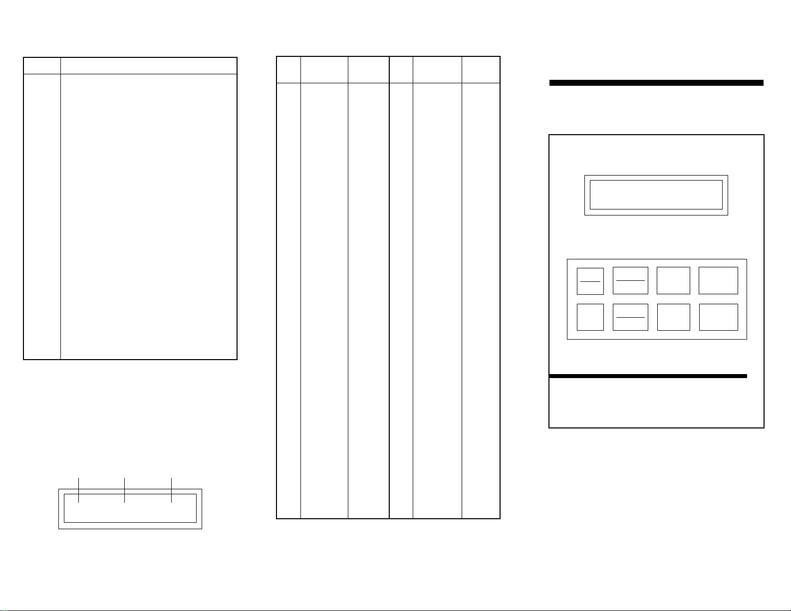
RUN 60.00 HZ
PROG
RUN
AUTO
MAN
START
ENTER
FWD
REV
STOP
Micro Series
Quick Reference Guide
NOTE: Before installing and operating the MICRO SERIES
drive, please read and become familiar with the MICRO SERIES
Installation and Operation Manual.
Adjustable Speed AC Motor Control
2 OUTPUT ACCEL
In the example above, the second fault is being viewed, which is
an OUTPUT fault that occurred while the drive was accelerating.
FAULT
NUMBER
FAULT
MESSAGE
DRIVE
STATUS
MICRO SERIES FAULT HISTORY
Parameter 70 — FAULT HISTORY stores the last eight faults that
tripped the drive. The FAULT HISTORY indicates the number of
the fault (number 1 is the most recent fault), the fault message,
and the status of the drive at the time of the fault. An example is
shown below:
FAULT DESCRIPTION
OUTPUT Output Transistor fault. Output current exceeded 200%.
May be ground fault or short circuit.
LO VOLTS Low DC Bus Voltage fault. DC bus voltage dropped below 60%
May be low line voltage.
HI VOLTS High DC Bus Voltage fault. DC Bus voltage exceeded 120%.
May be overhauling load .
HI TEMP High Temperature fault. Heatsink or ambient temperature
too high.
OVERLOAD Current Overload fault. Output current exceeded 100% for
too long. VFD may be undersized.
PWR TRAN Power Transient fault.
PWR SAG Power Sag fault: New control board installed. Perform
factory reset using Parameter 65.
LANGUAGE Language EEPROM fault.
EXTERNAL External fault: TB-130 activated (Parameter 50).
DB ERROR Dynamic Brake fault. DB Resistors overloaded.
CONTROL Control Board fault. New solfware installed. Perform factory
reset using Parameter 65.
INTERNAL Internal fault
INTERN (#) Internal fault.
MC3000 FAULT MESSAGES
PARAMETER FACTORY PARAMETER FACTORY
NO. NAME DEFAULT NO. NAME DAFAULT
0 LINE VOLTS AUTO
1 SPEED #1 20.00 Hz
2 SPEED #2 20.00 Hz
3 SPEED #3 20.00 Hz
4 SPEED #4 20.00 Hz
5 SKIP #1 .00 Hz
6 SKIP #2 .00 Hz
7 BAND WID 1.00 Hz
8 ACCEL 30.0 SEC
9 DECEL 30.0 SEC
10 MIN FRQ .50 Hz
11 MAX FRQ 60.00 Hz
12 DC BRAKE .0 VDC
13 DC TIME .0 SEC
14 DYN BRAKE OFF
16 CURRENT 180%
17 MOTOR OL 100%
18 BASE 60.00 Hz
19 FX BOOST (NOTE 1)
20 AC BOOST .0%
21 SLIP COMP .0%
22 TORQUE CONSTANT
23 CARRIER 2.5 kHz
25 START NORMAL
26 STOP COAST
27 ROTATION FORWARD
28 AUTO/MAN BOTH
29 MANUAL KEYPAD
30 CONTROL LOCAL
31 UNITS HERTZ
32 HZ MULT 1
33 UNITS DP XXXX
34 LOAD MLT 100%
35 CONTRAST HIGH
39 TB5 MIN .00 Hz
40 TB5 MAX 60.00 Hz
42 TB10A OUT NONE
43 @TB10A 60.00 Hz
44 TB10B OUT NONE
45 @TB10B 125%
47 TB13A NONE
48 TB13B NONE
49 TB13C NONE
50 TB13D FAULT
52 TB14 OUT NONE
53 TB15 OUT NONE
54 RELAY NONE
58 ADDRESS 30
61 PASSWORD 0019
63 SOFTWARE (NOTE 2)
64 MONITOR ON
65 PROGRAM RESET 60
66 HISTORY MAINTAIN
70 FAULT HIST. (NOTE 2)
NOTE 1: REFER TO THE MICRO SERIES MANUAL.
NOTE 2: THESE PARAMETERS ARE VIEW-ONLY.
MICRO SERIES PARAMETERS
Micro Series
Intelligent Drive
Digital
LEESON SPEEDMASTER
BULLETIN #2452 3/98
Page 2
STOP 20.00 HZ
PROG
RUN
AUTO
MAN
START
ENTER
FWD
REV
STOP
Press the START key to start the drive. The START key
is only active in LOCAL mode.
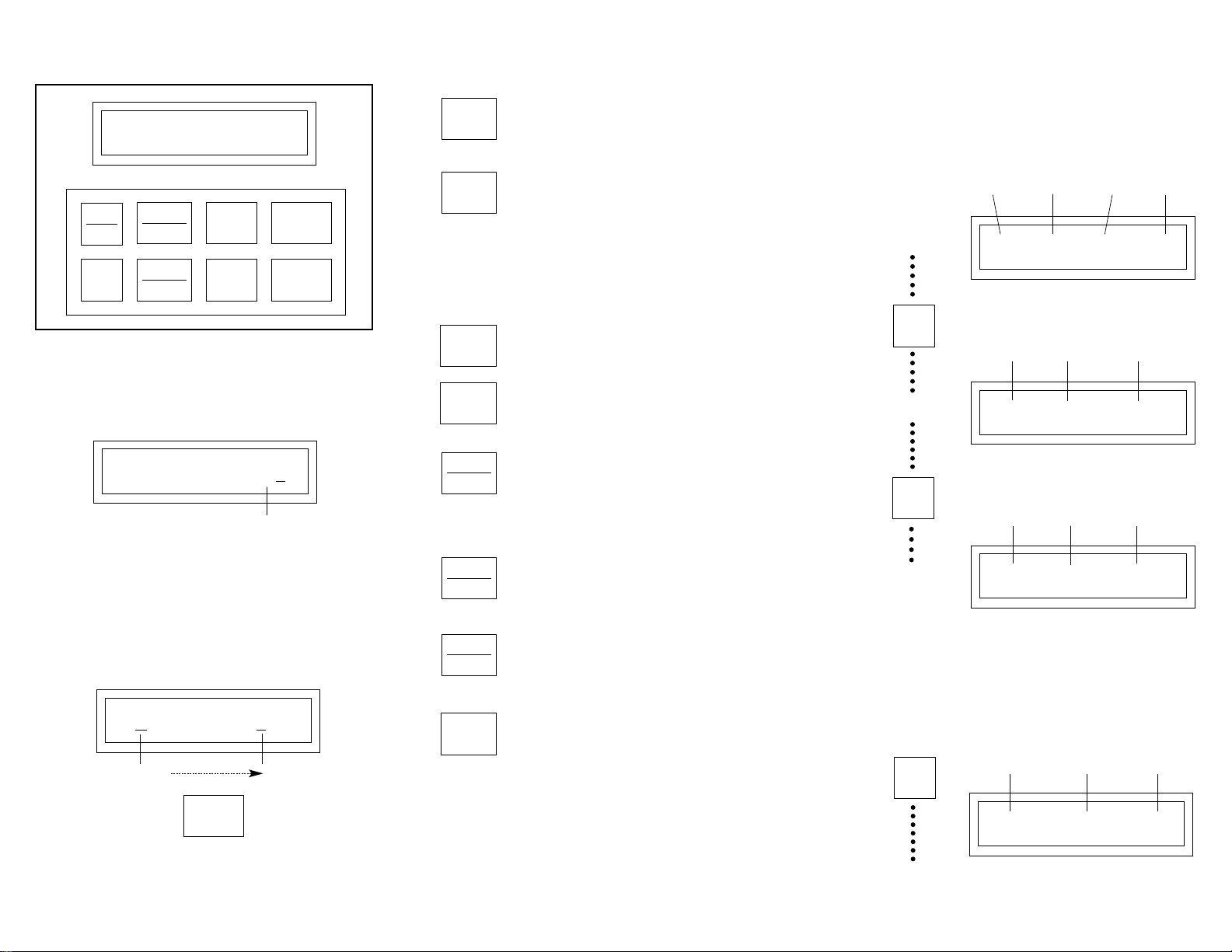
PROGRAMMING THE MICRO SERIES
1. Press the PROG/RUN key. This will cause the PASSWORD
prompt to appear (unless the password protection has been disabled), as shown below:
PASSWORD 0000
CURSOR
2. Use the ARROW keys to scroll to the correct password value
(the factory default password is 0019) and press ENTER. The
PROGRAM mode will be entered at the start of the parameter
menu. Acursor will highlight the parameter name.
3. Use the ARROW keys to scroll to the desired parameter and
press ENTER. The cursor will shift from the parameter name
to the parameter value, as the example below illustrates:
ACCEL 30.0 SEC
CURSOR
ENTER
4. Use the ARROW keys to scroll to the desired parameter value,
and press ENTER to store the new value.
5. Press PROG/RUN to exit the PROGRAM mode.
START
MICRO SERIES KEYPAD FUNCTIONS
Press the STOP key to stop the drive.
NOTE: The STOP key is active in both LOCAL and
REMOTE mode.
The STOP key is also used to reset faults. If the fault
condition has passed, pressing the STOP key will clear
the fault and return the drive to a STOP condition.
STOP
UP and DOWN ARROWS — Used to change the speed
setpoint in MANUAL mode, scroll through the parameter menu, and change parameter values.
Toggles between AUTOMATIC (terminal strip) and
MANUAL (keypad) speed control.
NOTE: Parameter 28 — AUTO/MAN must be set to
BOTH for this key to be active.
AUTO
MAN
Toggles between forward and reverse directions.
ENTER key must pressed.
FWD
REV
Used to enter and exit the PROGRAM mode to set the
parameters.
PROG
RUN
ENTER
Used for: toggling the display between SPEED, LOAD,
and MOTOR VOLTAGE; confirming new parameter
values; confirming AUTO and MANUALspeed control
selections.
MICRO SERIES DISPLAYS
Shown below are examples of MICRO SERIES displays. To scroll
through the SPEED, LOAD, and MOTOR VOLTAGE displays,
press and release the ENTER key.
RUN 60.00 HZ
DRIVE
STATUS
SPEED
SETPOINT
SPEED
UNITS
RUN 85% LOAD
DRIVE
STATUS
PERCENT
LOAD
RUN 460 VAC
DRIVE
STATUS
MOTOR
VOLTAGE
MOTOR VOLTAGE
DISLAY
ENTER
ENTER
SPEED DISPLAY
LOAD DISPLAY
Press and hold the ENTER key to activate the AUXILIARY
MODE, which will toggle to a CONTROL DISPLAY. An example
is shown below:
ENTER
PRESS
& HOLD
LOCAL -- AUTO -- IDC
DRIVE
STATUS
MOTOR
VOLTAGE
SPEED
REFERENCE
SOURCE
AUXILIARY MODE
CONTROL DISPLAY
MICRO SERIES KEYPAD
ROTATION
DIRECTION
ROTATION
DIRECTION
ROTATION
DIRECTION
 Loading...