

Page 1
User Instructions
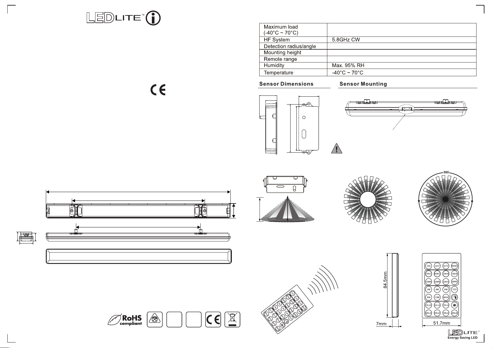
Sensor Specifications:
RTWPLED25MW
5ft 80W LED Non Corrosive
Weatherproof Fitting - IP65
with Microwave Sensor
IP65
Please read these instructions and retain them for future reference.
Important information
It is recommended that the fittings are installed by a qualified electrician ensuring the installation
complies to current IEE wiring regulations & local building control.
• These products are designed for connection to a 220-240V mains supply.
• We cannot accept responsibility for any claims arising from a poor installation.
Important User Advice
• Always switch off mains supply before installation.
• The fitting is suitable for indoor and outdoor use.
• The installation must not infringe on water pipes or any other electrical services.
• The light fitting is Class II and it does not require an earth connection.
Dimensions:
1480mm
1335mm
220-240V
35.8mm
23mm
90mm
98mm
Sensor Coverage:
41mm
LED - 500W
Max 15m / 360
Max 6m
10m
0
Sensor
This is a sealed fitting and must not be opened!
Opening this fitting will void the warranty!
80mm
118mm
69.5mm
Specifications:
• Voltage Range: 220-240V
• Nom. Watts: 80W
• Lumen Output: 8400lm
• Colour Temp.: 5000K
• IP Rating: IP65
• Warranty: 3 Years
• ABS Base
• Stainless Steel Clips
• Not Dimmable
15-06-2017
1270mm
Package Includes:
• Snap-in Metal clips x 2pcs.
• Plastic Wall Plugs x 4pcs.
• Screws x 4pcs.
• RC-102-B Remote Control
NON DIMMABLE
IP65
230V
50/60Hz
2.4 - 6m
118mm
Height of installation: 2.4 - 6m
Detection Range 15m
(installation height 2.4-6m)
Detection Angle
Remote Control Specifications: Remote Control Dimensions(mm):
● Control Range: up to 10m
● Battery Type: CR2025
Page 2

Installation:
Warning!
Switch off the power source before installation & maintenance
Step 1: Identify the location and direction of any hidden supply cables or service pipes before
drilling fixing holes.
Step 2: Mark and drill mounting holes for the snap-in ceiling clips at the correct spacing (Fig.1).
100mm
58mm
(Fig.1)
24mm
Step 3: Fix the clips securely to the ceiling (A).
Step 4: Using a screw loosen and open the cover for the connection Block 1 and wire the main
input to the terminal block of the light fitting (B). The fitting comes pre-wired as a standard single
fitting (Fig.2) with a link between Live(L) and Output (OUT) connections and it can be wired as
a Master to Slave sensor fitting by connecting the Orange wire from Master (M) to the
Output (OUT) connection (Fig.3). Connection Block 2 is used for output only (Fig. 4).
For detailed wiring see the instructions below.
Step 5: Close the connection box cover (C) on the connection Block 1 and mount the light fitting
onto the metal clips ensuring that it is secured into place (D).
Step 6: Power up the fitting to check that it functions correctly (E).
Installation*
The fitting comes with both waterproof cable
glands installed, one side has a silicone cover
to ensure the IP65 rating. In order to utilize
both connections, remove the blanking plate
by unscrewing the cover.
Wiring Instructions:
Connection Block 1(Input)
Standard Wiring
POWER SUPPLY LIGHT FITTING
1(Input)
2(Output)
(Fig.2)
(N)
(L)
(OUT)
(Orange)
(M)
Connection Block 1(Input)
Master to Slave Wiring
POWER SUPPLY LIGHT FITTING
(N)
(Fig.3)
(L)
(OUT)
(Orange)
(M)
Connection Block 2 (Output)
Live
(Fig.4)
(Brown)
Neutral
(Blue)
*Can also be suspended with traditional hooks & Jack chain. Not supplied.
Neutral
(Blue)
Live
(Black)
Output
(Brown)
Master
(Red)
Neutral
(Blue)
Live
(Black)
Output
(Brown)
Master
(Red)
NEXT LIGHTLIGHT FITTING
(L)
L
(N)
N
Remote Control Setup:
● Pull plastic protection from battery compartment to activate the remote control.
● The factory settings by default are:
○ Range (sensitivity) 10 metres distance.
○ Time ( the time the fitting will stay on for) is 10 seconds.
○ (The light sensitivity) By default the sensor will function all day and night (2000Lux).
● Changing the default settings:
○ Point the remote towards the fitting within 10m metres and press the AUTO button.
○ Select the mode of adjustment required, eg, sensitivity (range). Press the required range be
it 2m, 4m, 10m etc.
○ The light will then flash once acknowledging the new setting.
○ Repeat the same for all other adjustments required (stand-by time, lux).
Remote Control Functions:
Light ON/OFF
ON - Manual ON switch
OFF - Manual OFF switch
overriding the sensor.
(sensor disabled in this mode)
After 6 hours the sensor goes
back into "AUTO" mode.
Time Adjustment
Min: 10 Sec.
Max: 60 Min.
Range Adjustment
MAX detection distance 14-15m
10m detection distance
8m detection distance
6m detection distance
4m detection distance
2m detection distance
Lux Level Adjustment
Set daylights threshold from
10lux to 2000lux.
For daylight mode use 500lux
to 2000lux settings.
Lux Level Overwrite
Sets the surrounding lux value as
the daylight threshold (overwrites
the existing lux values).
Allows the fitting to function in any
desired light circumstances.
AUTO Mode
The sensor starts to work
automatically and all settings
remain the same as the latest
status before pushing ON/OFF
button, Test or Reset button.
Resets all functions
Default settings:
• 10m range
• 10 sec.
• 2000lux - Daylight mode
Test Mode
Hold the button for 2 seconds to
enter test mode. Time and lux
level are disabled in Test Mode.
Press Auto button to exit Test
Mode.
Permanent Lock Mode
Permanent inhibition of the
sensor - light permanent ON/OFF.
Only the ON and OFF functions
on the remote are available.
Press button again to exit mode.
Operation Modes:
● ON/OFF Mode
○ When ON/OFF buttons are pressed the light is turned ON/OFF overriding the
sensor. The Batten fitting will enter AUTO mode after 6 hours.
○ To exit ON/OFF Mode press AUTO button.
● LOCK/UNLOCK Mode
○ When is pressed the remote control is locked, only ON and OFF functions on the remote are
available.
○ Push the button again to unlock the remote control.
 Loading...