

Page 1
User Instructions
RTWPLED25M3
Emergency 5ft 80W LED Non Corrosive
Weatherproof Fitting - IP65
IP65
Please read these instructions and retain them for future reference.
Important information
It is recommended that the fittings are installed by a qualified electrician ensuring the installation
complies to current IEE wiring regulations & local building control.
• These products are designed for connection to a 220-240V mains supply.
• We cannot accept responsibility for any claims arising from a poor installation.
Important User Advice
• Always switch off mains supply before installation.
• The fitting is suitable for indoor and outdoor use.
• The installation must not infringe on water pipes or any other electrical services.
• The light fitting is Class II and it does not require an earth connection.
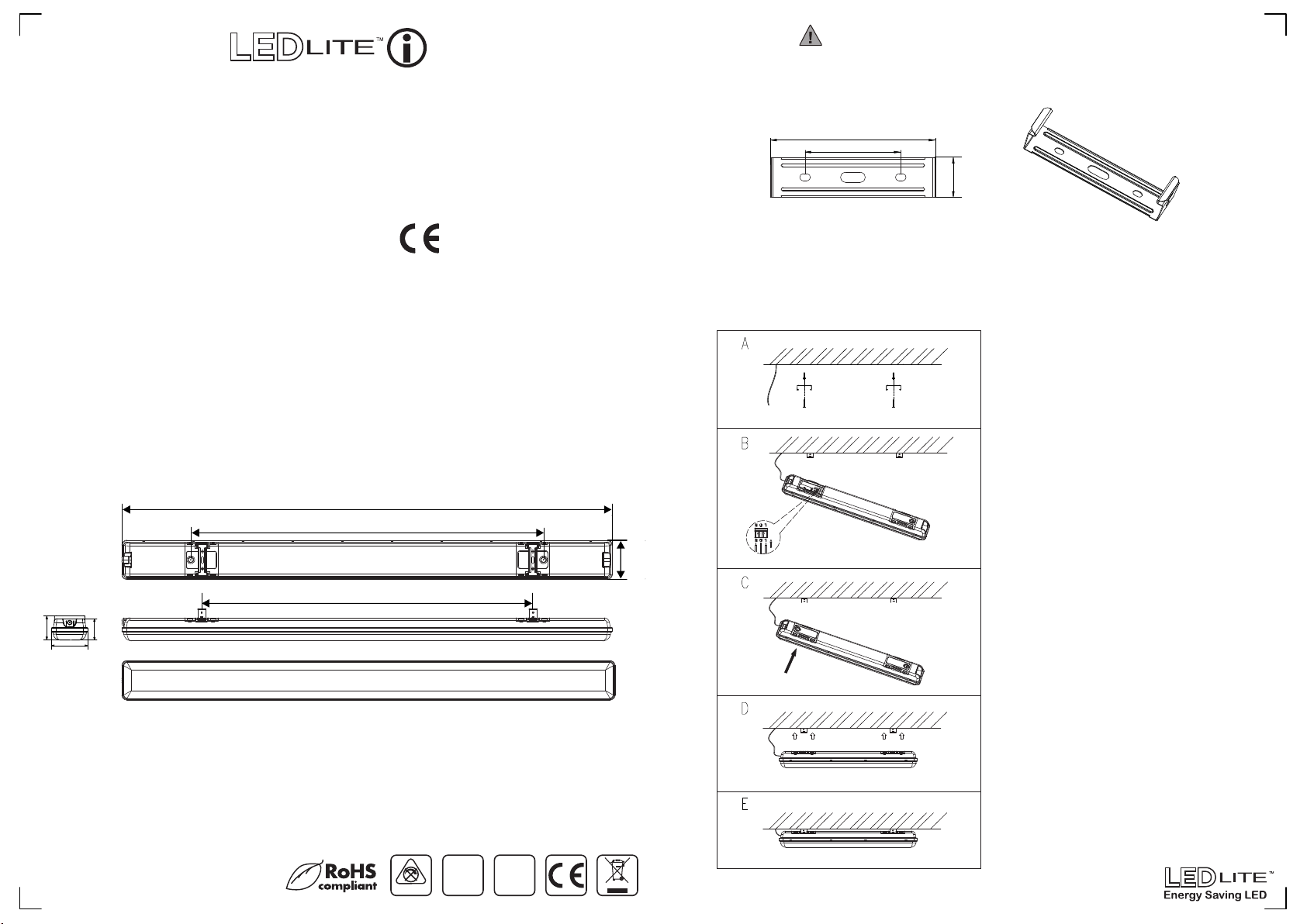
Dimensions:
1480mm
1335mm
1270mm
80mm
118mm
Specifications:
• Voltage Range: 220-240V
• Nom. Watts: 80W
• Lumen Output: 8400lm
• Colour Temp.: 5000K
• IP Rating: IP65
• Warranty: 3 Years
• ABS Base
• Stainless Steel Clips
• Not Dimmable
15-06-2017
69.5mm
Emergency Specifications:
• Emergency Wattage: 5W
• Battery Type: 6V / 4.4Ah NiCd
Package Includes:
• Snap-in Metal clips x 2pcs.
• Plastic Wall Plugs x 4pcs.
• Screws x 4pcs.
NON DIMMABLE
220-240V
IP65
230V
50/60Hz
Installation:
Step 1: Identify the location and direction of any hidden supply cables or service pipes before
drilling fixing holes.
Step 2: Mark and drill mounting holes for the snap-in ceiling clips at the correct spacing - see
minimum/maximum spacing (Fig.1).
Warning!
100mm
58mm
(Fig.1)
Step 3: Fix the clips securely to the ceiling (A)
Step 4: Using a screw loosen and open the cover for the connection block 1 (input) and wire
the main input to the terminal block of the light fitting (B).
In addition, a secondary permanent live supply should be fed to the fixture, in line with the
switch mains supply. The permanent supply MUST be taken from the same phase as the
switch live supply and MUST be wired so that upon test, it is isolated at the same time as the
switch supply.
118mm
*Can also be suspended with traditional hooks & Jack chain. Not supplied.
Installation*
1(Input)
Switch off the power source before installation & maintenance
24mm
For detailed wiring instructions see Fig. 2
(input) and Fig. 3 (output) on the next page.
Step 5: Close the connection box cover (C)
and mount the light fitting onto the metal clips
ensuring that it is secured into place (D).
Step 6: Power up the fitting to check that it
functions correctly (E).
The fitting has a switch for the emergency
2(Output)
light installed in the OUTPUT connector box:
● Turn the switch ON for the fitting to work
on emergency mode.
● Turn the switch OFF to use it as a standard
weatherproof fitting.
The green LED fitted to the luminaire should
be on after reconnecting the power supply,
indicating that the batteries are charging.
The batteries should be charged for at least
24 hours before carrying out a full discharge
test to check if the maintained duration is
being achieved.
The fitting comes with both waterproof cable
glands installed, one side has a silicone cover
to ensure the IP65 rating. In order to utilize
both connections, remove the blanking plate
by unscrewing the cover.
Page 2
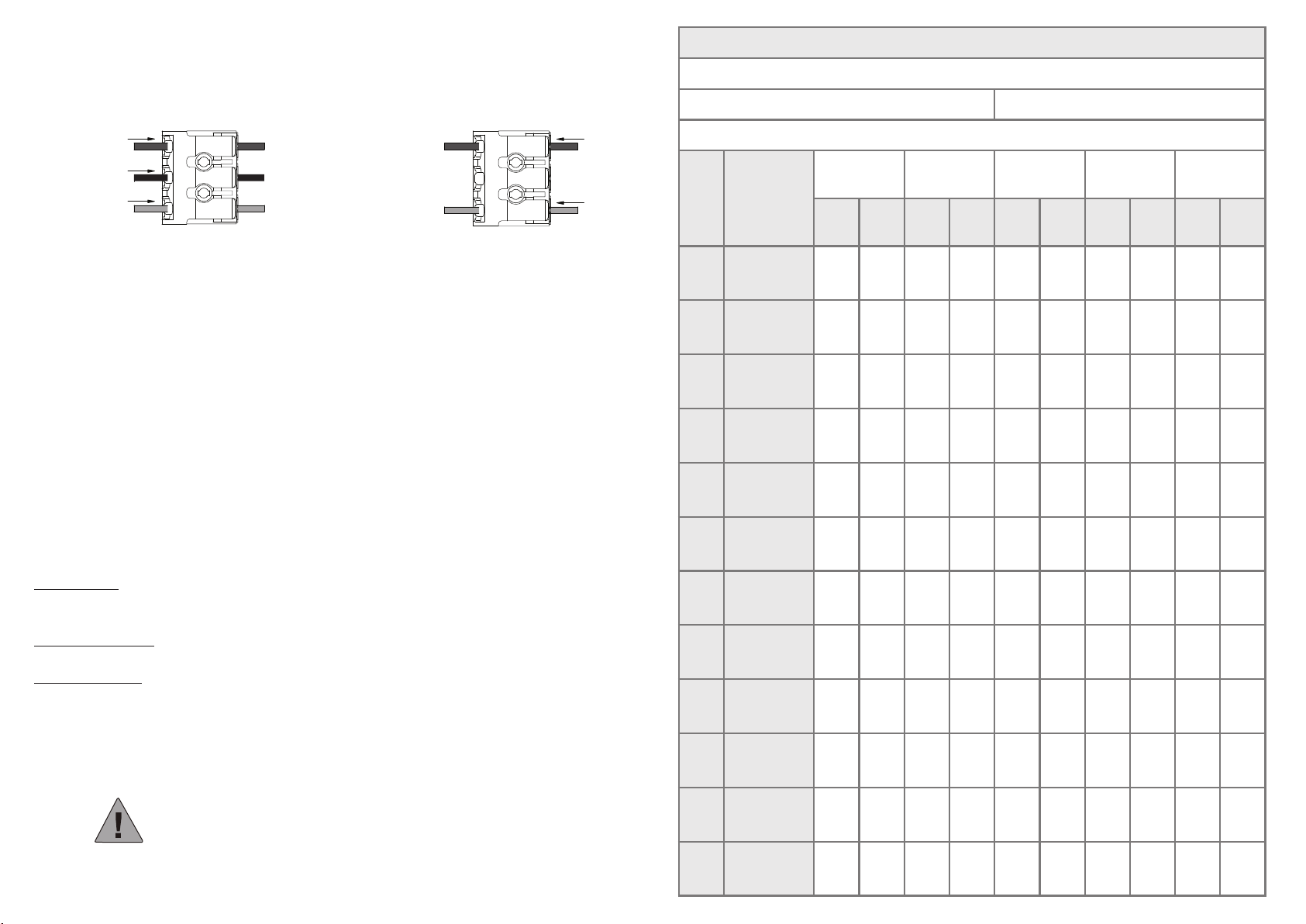
Wiring Instructions:
INSTALLATION, MAINTENANCE AND OPERATION CHECK RECORD
Connection Block 1 (Output)
Switch Live
(Brown)
Permanent Live
(Black)
Neutral
(Blue)
(Fig.2)
SL
PL
N
POWER SUPPLYLIGHT FITTING
(Switch L)
(Perm L)
(N)
Connection Block 2 (Output)
NEXT LIGHTLIGHT FITTING
Live
(Brown)
Neutral
(Blue)
L
N
(Fig.3)
(L)
(N)
OPERATION / MAINTENANCE
1. Nominal battery life is 4 years, after which time they should be replaced with a suitable equivalent.
2. When the lamp operates from the battery supply it will be at a reduced light level.
3. Keep the luminaire clean so it will not affect performance.
OPERATIONS CHECK
Periodic testing should be carried out by simulating a failure of supply, causing the fitting
to be energised from its battery. Interruption of the supply should be carried out by the operation
of a local key switch or other isolation device. During this period all fittings should be examined
visually to ensure that they are functioning correctly. At the end of the test period the supply
should be restored and all indicator lamps or devices checked to ensure that the normal supply
has been restored.
Location:
Installation Date:
Installed By:
Month Test
1
2
3
4
5
Short
Short
Short
Short
Short
Installation Test Duration:
Year: Year: Year: Year: Year:
Sign
Date
Sign
Date
Sign
Date
Sign
Date
Sign
Date
The duration of the simulated failure should be:
Each month:
Isolate the power supply and check the light is illuminated. This test should last for no more than
45 minutes. Complete the test record form supplied.
Every six months:
Isolate the power supply and check that the light is still illuminated after 1 hour.
Once each year:
Isolate the power supply and check that the light is still illuminated after 3 hours. Complete the test
record form.
This is a sealed fitting and must not be opened!
Opening this fitting will void the warranty!
For further information visit www.tlc-direct.co.uk
6
7
8
9
10
11
12
1 hr Endurance
Short
Short
Short
Short
Short
3 hr Endurance
 Loading...