

Page 1
LTDL3NMST - 3W LED Self-Test Non Maintained Emergency Downlight
IP20 220-240V 3W
Please read these instructions before commencing installation & retain them for
future reference.
Important information:
It is recommended that luminaires are installed by a qualified electrician ensuring the
installation complies to current IEE wiring regulations & local building control.
• These products are designed for connection to a 220-240V mains supply.
• Any broken or damaged parts should be replaced as soon as possible.
• We will not accept responsibility for any claims arising from a poor installation.
Important User Advice:
• Always switch off mains supply before servicing.
• This Iuminaire is suitable for indoor use only and should not be fitted to damp or wet
surfaces such as freshly plastered or painted walls or ceilings.
• This product is designed for permanent connection to fixed wiring: this must be
a suitable circuit (protected with the appropriate MCB or fuse).
• Do not cover the fitting, battery and driver with any insulating materials.
• This product is Class II, double insulated and does not require an earth connection.
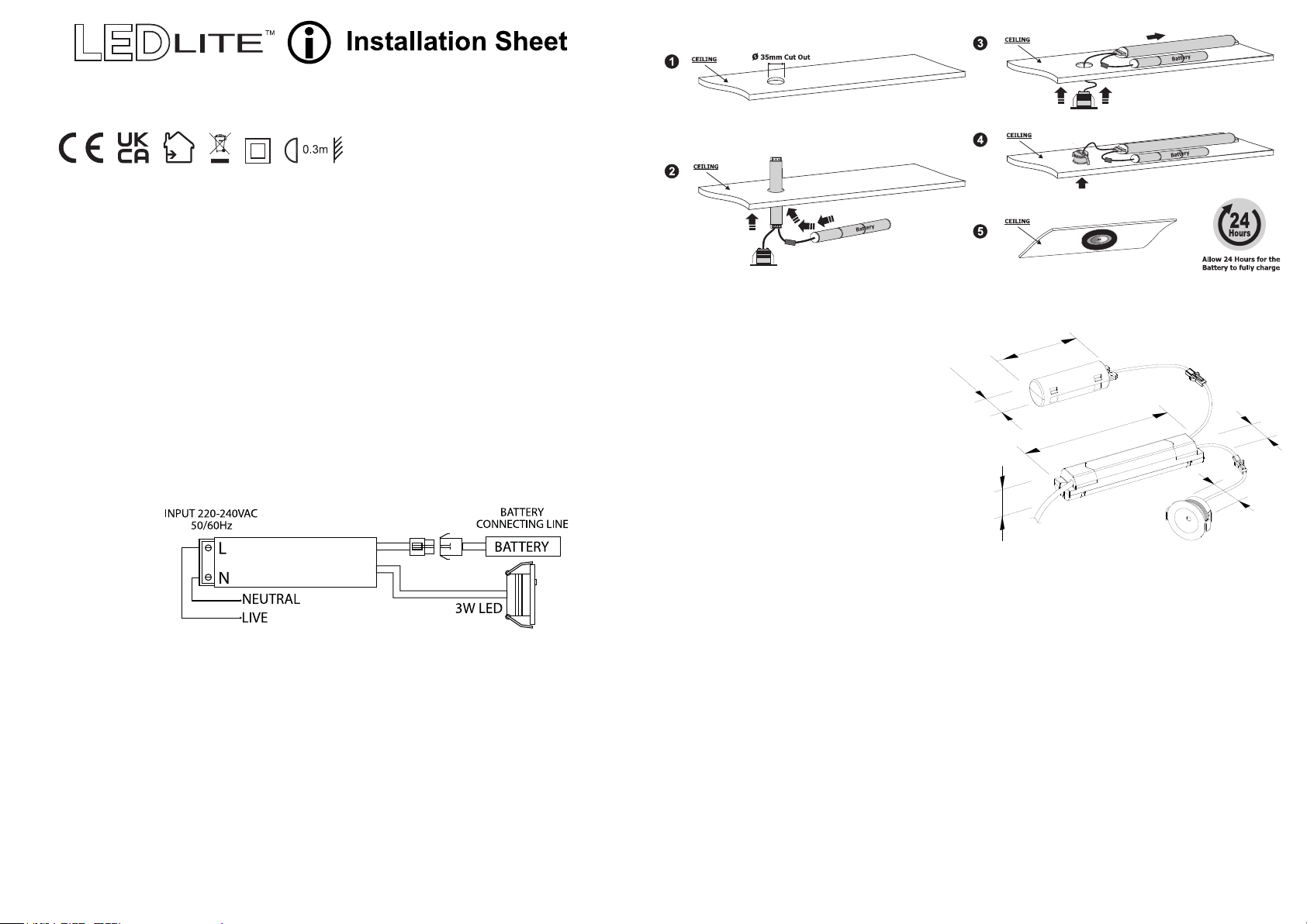
Wiring Diagram:
EMERGENCY DRIVER
(Blue)
(Brown)
Installation Procedure:
• Choose the installation location for the downlight and mark it. Cut a 34mm diameter
hole in the ceiling ensuring it does not infringe with electrical cables, water/gas pipes or
ceiling joists.
• Prepare the route for the mains cable and feed through the hole and make the
L & N connections to the input side of the driver/inverter. Feed the driver/inverter through
the hole, followed by the battery pack, which can lay adjacent to the hole.
• Feed the excess cable through the hole and press the down light into position until it is
retained by the springs. The fitting may require some manipulation in order to pass
through the hole. Do not enlarge the hole to make fitting easier.
• Restore the power and check if the fitting is working correctly. The LED will illuminate
green on normal operational mode, which indicates the fitting is charging.
• On mains power failure the LED will illuminate white light continuously for 3 hours
minimum.
MANUAL
TEST BUTTON
Specifications:
• Input Voltage: 220-240V/AC
• Power: 3W
• Light Output: 120Lm
• Test method: Self-test
• CCT: 5500K
• CRI >85
• IP Rating: IP20
• Protection Class: Class II
• Housing: PC Body
White Painted Aluminium Trim
• Ceiling Recessed Mounting
• Cut-out: Ø34mm
• Battery: LiFePO4 3.2V 1500mAh
• Warranty: 3 years
Dimensions (mm):
85
∅
27
25
150
29
∅
34
Emergency Testing and Battery Maintenance:
• Initial battery charge must be for a minimum of 24 hours before testing.
• To achieve best performance the LTDL3NMST should be tested fully by switching into
emergency mode regularly in accordance with local testing regulations. Any warranty
claim must be accompanied by documentation which records the dates of this
maintenance procedure and signed by maintenance personnel.
• When first connecting to AC power check if the Green LED light is lit confirming that the
battery is charging.
• The battery must be replaced when the unit no longer meets the rated emergency
duration or if there is a battery fault.
Emergency Self-Test:
The LTDL3NMST self-test fitting performs a self-commisioning test at first power on.
After charging for 24 hours a full duration test (3 hours) is performed. Initial functional
and duration tests are randomly generated. They are then performed in accordance
with standard requirements (every 30 days for functional tests and every 52 weeks for
duration tests).
Page 2
Self Test Function:
• Monthly inspection: The system will perform a functional test every 30 days for 2 minutes
that simulates a mains failure and checks the operation of the emergency light source from
the battery supply. The green indicator LED slowly flashes whilst the 2 minutes functional
test is in progress. It will quit and return to the mains power state automatically if there is
no fault.
• Annual inspection: The system will perform a duration test every 360 days for 3 hours or
until the battery power is dissipated. The duration test simulates a mains failure and checks
the operation of the light source from the battery supply for the rated duration. The indicator
LED fast flashes green whilst the duration test is in progress. It will quit and return to the
mains power state automatically if there is no fault.
Manual Test Button Function:
• Functional Test: Hold the test button for 5 seconds. The green indicator LED flashes slow
and the system performs a functional test for 30 seconds. It will quit and return to the mains
power state automatically if there is no fault.
• Duration test: Hold the test button for 7 seconds. The green indicator LED flashes fast and
the system performs a duration test, simulating a power outage for 3 hours or until the
battery power is dissipated. It will quit and return to the mains power state automatically if
there is no fault.
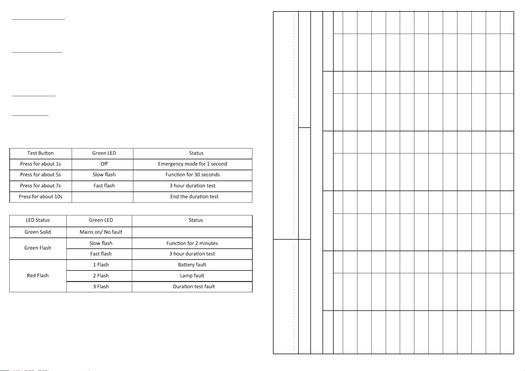
Test Button Functions:
LED Indicator Status:
Tel:
Lamp Type - LED
Year 4 Year 5
Date Signed Date Signed Date
ROUTINE TEST RECORD
Notes:
• To turn off emergency mode (mains failure) press the test button for 10 seconds
• Manual test will not affect the monthly and yearly test schedule.
Troubleshooting:
Most failures experienced are not due to the fitting itself and are caused by improper
installation or connection of the unit. Please check that:
• Wires are properly clamped into terminals.
• Installation is done according to the wiring diagram.
• Proper polarities are observed.
Year 1 Year 2 Year 3
Full Recharge Time 24 Hours Duration 3 Hours
Luminaire Ref/Location In Case of difficulty, contact the Installation Engineer:
Functional
Monthly Test Signed Date Signed Date Signed
Functional
Functional
Functional
Functional
Functional
Functional
Functional
Functional
Functional
Functional
Duration (3Hr)
 Loading...