


 Loading...
EDS Device Servers User Guide
EDS4100
EDS8PR
EDS16PR
EDS32PR
Part Number 900-433
Revision E January 2007
Copyright & Trademark
© 2006, 2007 Lantronix. All rights reserved. No part of the contents of this book may be transmitted or reproduced in any form or by any means without the written permission of Lantronix. Printed in the United States of America.
Ethernet is a trademark of XEROX Corporation. UNIX is a registered trademark of The Open Group. Windows 95, Windows 98, Windows 2000, and Windows NT are trademarks of Microsoft Corp. Netscape is a trademark of Netscape Communications Corporation.
Contacts
Lantronix Corporate Headquarters
15353 Barranca Parkway
Irvine, CA 92618, USA
Phone: 949-453-3990
Fax: 949-453-3995
Technical Support
Online: www.lantronix.com/support
Sales Offices
For a current list of our domestic and international sales offices, go to the Lantronix web site at www.lantronix.com/about/contact .
Disclaimer & Revisions
Operation of this equipment in a residential area is likely to cause interference, in which case the user, at his or her own expense, will be required to take whatever measures may be required to correct the interference.
Changes or modifications to this device not explicitly approved by Lantronix will void the user's authority to operate this device.
Attention: With the purchase of the EDS, the OEM agrees to an OEM firmware license agreement that grants the OEM a non-exclusive, royalty-free firmware license to use and distribute the binary firmware image provided, only to the extent necessary to use the EDS hardware. For further details, please see the EDS OEM firmware license agreement.
The information in this guide may change without notice. The manufacturer assumes no responsibility for any errors that may appear in this guide.
|
Date |
Rev. |
Comments |
|
3/06 |
A |
Initial Document |
|
10/06 |
B |
EDS16PR and EDS32PR products added. |
|
12/06 |
D |
German and English TUV certication added. |
|
1/07 |
E |
EDS8PR products added. |
EDS Device Servers User Guide |
2 |
Contents
1: Preface |
10 |
Purpose and Audience_______________________________________________ 10 Summary of Chapters _______________________________________________ 10 Additional Documentation ____________________________________________ 11
2: Introduction |
12 |
EDS4100 Overview _________________________________________________ 12
Features ______________________________________________________________ 13
EDS8PR, EDS16PR and EDS32PR Overview ____________________________ 13
Features ______________________________________________________________ 14
Evolution OS™ ____________________________________________________ 14
Web-Based Configuration and Troubleshooting _______________________________ 15 Command-Line Interface (CLI)_____________________________________________ 15 SNMP Management_____________________________________________________ 15 XML-Based Architecture and Device Control__________________________________ 15 Rich Site Summary (RSS) ________________________________________________ 15 Enterprise-Grade Security ________________________________________________ 15 Troubleshooting Capabilities ______________________________________________ 16
Applications _______________________________________________________ 17
Building Automation/Security ______________________________________________ 17 Industrial Automation ____________________________________________________ 17 Medical/Healthcare______________________________________________________ 17 Retail Automation/Point-of-Sale ____________________________________________ 18 Console Management ___________________________________________________ 18 Traffic Management _____________________________________________________ 18
3: Installation: EDS4100 |
19 |
Package Contents __________________________________________________ 19 User-Supplied Items ________________________________________________ 19 Identifying Hardware Components______________________________________ 20
Serial Ports____________________________________________________________ 21 Ethernet Port __________________________________________________________ 22 Terminal Block Connector ________________________________________________ 22 LEDs_________________________________________________________________ 22 Reset Button___________________________________________________________ 23
Physically Installing the EDS4100 ______________________________________ 23
EDS Device Servers User Guide |
3 |

Contents
Finding a Suitable Location _______________________________________________ 23
Connecting the EDS4100_________________________________________________ 23
4: Installation: EDS8PR, EDS16PR and EDS32PR |
25 |
Package Contents __________________________________________________ 25 User-Supplied Items ________________________________________________ 25 Identifying Hardware Components______________________________________ 26
Serial Ports____________________________________________________________ 27
Ethernet Port __________________________________________________________ 27
LEDs_________________________________________________________________ 27
Reset Button___________________________________________________________ 28
Physically Installing the EDS8/16/32PR__________________________________ 28
Finding a Suitable Location _______________________________________________ 28
Connecting the EDS8/16/32PR ____________________________________________ 28
5: Getting Started |
30 |
Using DeviceInstaller ________________________________________________ 30
Starting DeviceInstaller __________________________________________________ 30
Viewing EDS Properties__________________________________________________ 31
Configuration Methods_______________________________________________ 32
Configuring from the Web Manager Interface _________________________________ 32 Configuring via an SSH/Telnet Session or Serial Port Using the CLI _______________ 32 Configuring from the XML Interface _________________________________________ 33
6: Configuration Using the Web Manager |
34 |
Accessing the Web Manager through a Web Browser ______________________ 34 Navigating Through the Web Manager __________________________________ 36 Understanding the Web Manager Pages _________________________________ 42 Device Status Page _________________________________________________ 43
7: Network, Serial Line, and Tunnel Settings |
44 |
Network Configuration Page __________________________________________ 44 Line Settings Pages _________________________________________________ 47
Line – Statistics Page____________________________________________________ 48 Line - Configuration Page ________________________________________________ 49 Line – Command Mode Page _____________________________________________ 51
Tunnel Pages______________________________________________________ 52
Tunnel – Statistics Page _________________________________________________ 52 Tunnel – Serial Settings Page _____________________________________________ 53 Tunnel – Start/Stop Characters Page _______________________________________ 55 Tunnel – Accept Mode Page ______________________________________________ 56
EDS Device Servers User Guide |
4 |

Contents
Tunnel – Connect Mode Page _____________________________________________ 59 Tunnel – Disconnect Mode Page ___________________________________________ 62 Tunnel – Packing Mode Page _____________________________________________ 64 Tunnel – Modem Emulation Page __________________________________________ 65 Tunnel – AES Keys Page_________________________________________________ 67
8: Services Settings |
70 |
DNS Page ________________________________________________________ 70 SNMP Page _______________________________________________________ 71 FTP Page_________________________________________________________ 72 TFTP Page________________________________________________________ 74 Syslog Page_______________________________________________________ 75 HTTP Pages ______________________________________________________ 76
HTTP Statistics Page ____________________________________________________ 76 HTTP Configuration Page ________________________________________________ 77 HTTP Authentication Page________________________________________________ 79 HTTP RSS Page _______________________________________________________ 82
9: Security Settings |
84 |
SSH Pages _______________________________________________________ 84
SSH Server: Host Keys Page _____________________________________________ 84 SSH Client: Known Hosts Page ____________________________________________ 86 SSH Server: Authorized Users Page ________________________________________ 88 SSH Client: Users Page__________________________________________________ 89
SSL Page_________________________________________________________ 92
10: Maintenance and Diagnostics Settings |
95 |
Filesystem Pages___________________________________________________ 95
Filesystem Statistics Page ________________________________________________ 95
Filesystem Browser Page ________________________________________________ 96
Diagnostics Pages __________________________________________________ 98
Diagnostics: Hardware Page ______________________________________________ 98 MIB-II Network Statistics Page_____________________________________________ 99 IP Sockets Page_______________________________________________________ 100 Diagnostics: Ping Page _________________________________________________ 101 Diagnostics: Traceroute Page ____________________________________________ 102 Diagnostics: DNS Lookup Page___________________________________________ 103 Diagnostics: Memory Page ______________________________________________ 104 Diagnostics: Buffer Pool_________________________________________________ 105 Diagnostics: Processes Page ____________________________________________ 106
System Page _____________________________________________________ 107
EDS Device Servers User Guide |
5 |

Contents
Query Port Page __________________________________________________ 109
11: Advanced Settings |
111 |
Email Pages______________________________________________________ 111
Email Statistics Page ___________________________________________________ 111
Email Configuration Page _______________________________________________ 112
CLI Pages _______________________________________________________ 114
Command Line Interface Statistics Page ____________________________________ 114
Command Line Interface Configuration Page ________________________________ 115
XML Pages ______________________________________________________ 117
XML Configuration Record: Export System Configuration Page __________________ 117 XML Status Record: Export System Status __________________________________ 119 XML: Import System Configuration Page____________________________________ 120
Protocol Stack Page _______________________________________________ 122 IP Address Filter Page ______________________________________________ 124
12: Updating Firmware |
126 |
Obtaining Firmware ________________________________________________ 126 Upgrading Using DeviceInstaller ______________________________________ 126
Loading New Firmware _________________________________________________ 126
Updating the Boot Loader from DeviceInstaller _______________________________ 126
Updating Firmware_____________________________________________________ 127
A: Factory Default Configuration |
128 |
Network Configuration Settings _______________________________________ 128 Serial Port Line Settings ____________________________________________ 128 Tunnel Settings ___________________________________________________ 129
Serial Settings ________________________________________________________ 129 Start/Stop Characters___________________________________________________ 129 Accept Mode _________________________________________________________ 130 Connect Mode ________________________________________________________ 130 Disconnect Mode ______________________________________________________ 131 Packing Mode_________________________________________________________ 131 Modem Emulation _____________________________________________________ 131 AES Keys ____________________________________________________________ 132
DNS Settings _____________________________________________________ 132 SNMP Settings____________________________________________________ 132 FTP Settings _____________________________________________________ 133 TFTP Settings ____________________________________________________ 133 Syslog Settings ___________________________________________________ 133
EDS Device Servers User Guide |
6 |

Contents
HTTP Settings ____________________________________________________ 134
Configuration _________________________________________________________ 134
Authentication_________________________________________________________ 134
RSS ________________________________________________________________ 134
CLI Settings ______________________________________________________ 135
Telnet _______________________________________________________________ 135
Email Settings ____________________________________________________ 135 Query Port Settings ________________________________________________ 136 Diagnostics Settings _______________________________________________ 136
Ping ________________________________________________________________ 136
System Settings ___________________________________________________ 136 IP Address Filter __________________________________________________ 136
B: Technical Specifications |
137 |
EDS4100 ________________________________________________________ 137 EDS8/16/32PR____________________________________________________ 139
C: Networking and Security |
141 |
SSL ____________________________________________________________ 141
Benefits of SSL________________________________________________________ 141
How SSL Works _______________________________________________________ 142
Digital Certificates _____________________________________________________ 142
SSH ____________________________________________________________ 143
How Does SSH Authenticate? ____________________________________________ 143
What Does SSH Protect Against? _________________________________________ 143
Tunneling ________________________________________________________ 144
Tunneling and the EDS _________________________________________________ 145 Connect Mode ________________________________________________________ 145 Accept Mode _________________________________________________________ 146 Disconnect Mode ______________________________________________________ 146 Packing Mode_________________________________________________________ 147
Modem Emulation _________________________________________________ 147
Command Mode_______________________________________________________ 148
D: Technical Support |
150 |
E: Lantronix Cables and Adapters |
151 |
F: Compliance |
152 |
Lithium Battery Notice ______________________________________________ 153 Installationsanweisungen____________________________________________ 153
Rackmontage _________________________________________________________ 153
EDS Device Servers User Guide |
7 |

Contents
Energiezufuhr _________________________________________________________ 153
Erdung ______________________________________________________________ 153
Installation Instructions _____________________________________________ 153
Rack Mounting ________________________________________________________ 153
Input Supply __________________________________________________________ 154
Grounding____________________________________________________________ 154
G: Warranty |
155 |
Index |
156 |
Figures |
|
Figure 2-1. EDS4100 4 Port Device Server.............................................................. |
13 |
Figure 2-2. EDS16PR Device Server........................................................................ |
14 |
Figure 3-1. Front View of the EDS4100..................................................................... |
20 |
Figure 3-2. Back View of the EDS4100 ..................................................................... |
20 |
Figure 3-3. RS-232 Serial Port Pins (Serial Ports 1, 2, 3, 4) ..................................... |
21 |
Figure 3-4. RS-422/RS-485 Serial Port Pins ............................................................. |
21 |
Figure 3-5. Terminal Block Connector Pin Assignments ........................................... |
22 |
Figure 3-6 .Back Panel LEDs..................................................................................... |
22 |
Figure 3-7. Example of EDS4100 Connections ......................................................... |
24 |
Figure 4-1. Front View of the EDS16PR.................................................................... |
26 |
Figure 4-2. Back View of the EDS16PR .................................................................... |
26 |
Figure 4-3. RJ45 Serial Port ...................................................................................... |
27 |
Figure 4-4. Example of EDS16PR Connections ........................................................ |
29 |
Figure 5-1. Lantronix DeviceInstaller ........................................................................ |
30 |
Figure 5-2. EDS4100 Properties................................................................................ |
31 |
Figure 6-1. Prompt for User Name and Password..................................................... |
34 |
Figure 6-2. Web Manager Device Status Page ......................................................... |
35 |
Figure 6-3. Web Manager Menu Structure (1 of 4).................................................... |
38 |
Figure 6-4. Web Manager Menu Structure (2 of 4).................................................... |
39 |
Figure 6-5. Web Manager Menu Structure (3 of 4).................................................... |
40 |
Figure 6-6. Web Manager Menu Structure (4 of 4).................................................... |
41 |
Figure 6-7. Components of the Web Manager Page................................................. |
42 |
Figure 6-8. Device Status Page (EDS4100) .............................................................. |
43 |
Figure 7-1. Network Configuration............................................................................. |
45 |
Figure 7-2. Line –Statistics Page ............................................................................... |
48 |
Figure 7-3. Configuration Page.................................................................................. |
49 |
Figure 7-4. Line – Command Mode Page.................................................................. |
51 |
Figure 7-5. Tunnel - Statistics Page.......................................................................... |
53 |
Figure 7-6. Tunnel – Serial Settings Page................................................................. |
54 |
Figure 7-7. Tunnel – Start/Stop Chars Page ............................................................. |
55 |
Figure 7-8. Tunnel – Accept Mode Page .................................................................. |
57 |
Figure 7-9. Connect Mode Page................................................................................ |
60 |
Figure 7-10. Tunnel – Disconnect Mode Page .......................................................... |
63 |
Figure 7-11. Tunnel – Packing Mode Page ............................................................... |
64 |
Figure 7-12. Tunnel – AES Keys Page...................................................................... |
68 |
Figure 8-1. DNS Page................................................................................................ |
70 |
Figure 8-2. SNMP Page............................................................................................. |
71 |
Figure 8-3. FTP Page................................................................................................. |
73 |
Figure 8-4. TFTP Page .............................................................................................. |
74 |
EDS Device Servers User Guide |
8 |

|
Contents |
Figure 8-5. Syslog Page ............................................................................................ |
75 |
Figure 8-6. HTTP Statistics Page .............................................................................. |
76 |
Figure 8-7. HTTP Configuration Page ....................................................................... |
77 |
Figure 8-8. HTTP Authentication Page...................................................................... |
80 |
Figure 8-9. HTTP RSS Page ..................................................................................... |
82 |
Figure 9-1. SSH Server: Host Keys Page.................................................................. |
85 |
Figure 9-2. SSH Client: Known Hosts Page .............................................................. |
87 |
Figure 9-3. SSH Server: Authorized Users Page ...................................................... |
88 |
Figure 9-4. SSH Client: Users Page .......................................................................... |
90 |
Figure 9-5. SSL Page................................................................................................. |
93 |
Figure 10-1. Filesystem Statistics Page..................................................................... |
95 |
Figure 10-2. Filesystem Browser Page...................................................................... |
96 |
Figure 10-3. MIB-II Network Statistics Page.............................................................. |
99 |
Figure 10-4 IP Sockets Page ................................................................................... |
100 |
Figure 10-5 Diagnostics: Ping Page ........................................................................ |
101 |
Figure 10-6 Diagnostics: Traceroute Page .............................................................. |
102 |
Figure 10-7 Diagnostics: DNS Lookup Page ........................................................... |
103 |
Figure 10-8 Diagnostics: Memory Page .................................................................. |
104 |
Figure 10-9. Diagnostics: Buffer Pools Page........................................................... |
105 |
Figure 10-10. Diagnostics: Processes Page............................................................ |
106 |
Figure 10-11. System Page ..................................................................................... |
108 |
Figure 10-12. Query Port Page................................................................................ |
110 |
Figure 11-1. Email Statistics Page........................................................................... |
112 |
Figure 11-2. Email Configuration Page.................................................................... |
113 |
Figure 11-3. Command Line Interface Statistics Page ............................................ |
115 |
Figure 11-4. Command Line Interface Configuration Page ..................................... |
116 |
Figure 11-5. XML Configuration Record: Export System Configuration Page......... |
118 |
Figure 11-6. XML Status Record: Export System Status Page ............................... |
119 |
Figure 11-7. XML: Import System Configuration Page ............................................ |
121 |
Figure 11-8. Protocol Stack Page ............................................................................ |
123 |
Figure 11-9. IP Address Filter Page......................................................................... |
125 |
EDS Device Servers User Guide |
9 |
1: Preface
Purpose and Audience
This guide describes how to install, configure, use, and update the EDS4100 4-Port, EDS8PR 8-Port, EDS16PR 16-Port, and EDS32PR 32-Port Device Servers. It is for users who will use the EDS to network-enable their serial devices.
Summary of Chapters
The remaining chapters in this guide include:
|
Chapter |
Description |
|
|
|
|
|
|
|
|
2: Introduction |
Main features of the EDS device servers and the |
||
|
|
applications for which they are suited. |
||
|
|
|
|
|
|
3: Installation: EDS4100 |
Instructions for getting the EDS4100 device server |
||
|
|
up and running. Includes a description of hardware |
||
|
|
components. |
||
|
|
|
|
|
|
4: Installation: EDS8PR, EDS16PR and |
Instructions for getting the EDS8PR, EDS16PR and |
||
|
EDS32PR |
EDS32PR device server up and running. Includes a |
||
|
|
description of hardware components. |
|
|
|
5: Getting Started |
Instructions for starting DeviceInstaller and viewing |
||
|
|
current configuration settings. Introduces methods |
||
|
|
of configuring the EDS. |
|
|
|
6:Configuration Using the Web Manager |
Instructions for using the web interface to configure |
||
|
|
EDS device servers. |
|
|
|
7: Network, Serial Line, and Tunnel |
Instructions for using the web interface to configure |
||
|
Settings |
network, serial line, and tunnel settings. |
|
|
|
8: Services Settings |
Instructions for using the web interface to configure |
||
|
|
settings for DNS, SNMP, FTP, and other services. |
|
|
|
9: Security Settings |
Instructions for using the web interface to configure |
||
|
|
SSH and SSL security settings. |
|
|
|
10: Maintenance and Diagnostics |
Instructions for using the web interface to maintain |
||
|
|
the EDS, view statistics, files, and logs, and |
||
|
|
diagnose problems. |
||
|
|
|
|
|
|
11: Advanced Settings |
Instructions for using the web interface to configure |
||
|
|
advanced settings, e.g., email, CLI, and XML. |
||
|
|
|
|
|
|
12:Updating Firmware |
Instructions for upgrading the EDS firmware. |
||
|
|
|
|
|
|
|
|
10 |
|
EDS Device Servers User Guide |
|
|||
|
|
1: Preface |
|
|
|
|
|
|
Chapter |
Description |
|
|
|
|
|
|
A: Factory Default Configuration |
Quick reference of the EDS factory-default |
|
|
|
configuration settings. |
|
|
B: Technical Specifications |
Tables of technical data about the products... |
|
|
|
|
|
|
C: Networking and Security |
In-depth description of networking and network |
|
|
|
security as it relates to the EDS device servers. |
|
|
D: Technical Support |
Information about contacting Lantronix Technical |
|
|
|
Support. |
|
|
F: Compliance |
Information about the products' compliance with |
|
|
|
regulatory standards. |
|
|
G:Warranty |
Provides information on the Lantronix warranty for |
|
|
|
the EDS. |
|
Additional Documentation
The following guide is available on the product CD or the Lantronix Web site: www.lantronix.com.
Document |
Description |
EDS Device Server |
Provides the steps for getting the EDS up and running. |
Quick Start Guide |
|
EDS Device Server |
Describes how to configure the EDS using Telnet or the serial port |
Command Reference |
and summarizes the CLI and XML configuration commands. |
Secure Com Port |
Provides information for using the Lantronix Windows-based utility to |
Redirector |
create secure virtual com ports. |
User Guide |
|
EDS Device Servers User Guide |
11 |
2: Introduction
This chapter introduces the Lantronix EDS family of device servers. It provides an overview of the products, lists their key features, and describes the applications for which they are suited.
EDS device servers contain all the components necessary to deliver full network connectivity to virtually any kind of serial device, a reliable TCP/IP protocol stack, and a variety of remote management capabilities. They boast an innovative design and run on Lantronix’s leading-edge Evolution OS™.
EDS4100 Overview
The EDS4100 is a compact, easy-to-use device server that gives you the ability to network-enable asynchronous RS-232 and RS-422/485 serial devices. It can deliver fully transparent RS-232/422 point-to-point connections and RS-485 multi-drop connections without requiring modifications to existing software or hardware components in your application.
Note: RS-485 circuits support 32 full-load devices or 128 quarter-load devices. Each EDS4100 RS-485 port, however, counts as one device, leaving up to 31 full-load or 127 quarter-load devices that can be connected to the RS-485 circuit.
The EDS4100 device server supports the Power-over-Ethernet (PoE) standard. With PoE, power is supplied to the EDS over the Ethernet cable, by either an Ethernet switch or a midspan device. Being able to draw power through the Ethernet cable eliminates power supply and cord clutter. It also allows the EDS to be located in areas where power is not typically available.
Ports 1 through 4 support RS-232 devices.
Ports 1 and 3 also support RS-422/485 devices.
EDS Device Servers User Guide |
12 |

2: Introduction
Figure 2-1. EDS4100 4 Port Device Server
Features
The following list summarizes the key features of the EDS4100.
Includes four serial ports with hardware handshaking signals
Supports RS-232 and RS-422/485
Includes one RJ45 Ethernet port
Supports the IEEE 802.3af standard for Power-over-Ethernet (PoE)
8 MB Flash memory
32 MB Random Access Memory (RAM)
Based on Lantronix’s Evolution OS™
Supports secure data encryption by means of AES, SSH, or SSL sessions
Supports three convenient configuration methods (Web, command line, and XML)
EDS8PR, EDS16PR and EDS32PR Overview
The EDS8PR (8 serial ports), EDS16PR (16 serial ports), and EDS32PR (32 serial ports) are compact easy-to-use, rack-mountable device servers that give you the ability to network-enable asynchronous RS-232 serial devices. They provide fully transparent RS232 point-to-point connections without requiring modifications to existing software or hardware components in your application.
EDS Device Servers User Guide |
13 |

2: Introduction
Figure 2-2. EDS16PR Device Server
Features
The following list summarizes the key features of the EDS8PR,, EDS16PR and
EDS32PR.
Includes 8 (EDS8PR), 16 (EDS16PR) or 32 (EDS32PR) serial ports with hardware handshaking signals
Supports RS-232
Includes one RJ45 Ethernet port
8 MB Flash memory
32 MB Random Access Memory (RAM)
Based on Lantronix’s Evolution OS™
Includes a dedicated console port
Supports secure data encryption by means of AES, SSH, or SSL sessions
Supports three convenient configuration methods (Web, command line, and XML)
Evolution OS™
EDS device servers incorporate Lantronix’s Evolution OS™. Key features of the Evolution OS™ include:
Built-in Web server for configuration and troubleshooting from Web-based browsers
CLI configurability
SNMP management
XML data transport and configurability
Rich Site Summary (RSS) information feeds
Enterprise-grade security with SSL and SSH
Comprehensive troubleshooting tools
EDS Device Servers User Guide |
14 |

2: Introduction
Web-Based Configuration and Troubleshooting
Built upon popular Internet-based standards, the EDS enables users to configure, manage, and troubleshoot efficiently through a simplified browser-based interface that can be accessed anytime from anywhere. All configuration and troubleshooting options are launched from a well-organized, multi-page interface. Users can access all functionality via a Web browser, allowing them flexibility and remote access. As a result, users can enjoy the twin advantages of decreased downtime (based on the troubleshooting tools) and the ability to implement configuration changes easily (based on the configuration tools).
In addition, users can load their own Web pages onto the EDS to facilitate monitoring and control of their own serial devices that are attached to the EDS.
Command-Line Interface (CLI)
Making the edge-to-enterprise vision a reality, the EDS with the Evolution OS™ uses industry-standard tools for configuration, communication, and control. For example, the Evolution OS™ uses a Cisco®-like command line interface (CLI) whose syntax is very similar to that used by data center equipment such as routers and hubs.
SNMP Management
The EDS supports full SNMP management, making it ideal for applications where device management and monitoring are critical. These features allow networks with SNMP capabilities to correctly diagnose and monitor EDS device servers.
XML-Based Architecture and Device Control
XML is a fundamental building block for the future growth of M2M networks. The EDS supports XML-based configuration setup records that makes device configuration transparent to users and administrators. The XML is easily editable with a standard text or XML editor.
Rich Site Summary (RSS)
The EDS supports Rich Site Summary (RSS), a rapidly emerging technology for streaming and managing on-line content. RSS feeds all the configuration changes that occur on the device. The feed is then read (polled) by an RSS aggregator. More powerful than simple email alerts, RSS uses XML as an underlying Web page transport and adds intelligence to the networked device while not taxing already overloaded email systems.
Enterprise-Grade Security
Without the need to disable any features or functionality, the Evolution OS™ provides the EDS the highest level of security possible. This ‘data center grade’ protection ensures that each device on the M2M network carries the same level of security as traditional IT networking equipment in the corporate data center.
With built-in SSH and SSL, secure communications can be established between the EDS serial ports and the remote end device or application. By protecting the privacy of serial data being transmitted across public networks, users can maintain their existing
EDS Device Servers User Guide |
15 |

2: Introduction
investment in serial technology, while taking advantage of the highest data-protection levels possible.
SSH and SSL can:
Verify the data received came from the proper source
Validate that the data transferred from the source over the network has not changed when it arrives at its destination (shared secret and hashing)
Encrypt data to protect it from prying eyes and nefarious individuals
Provide the ability to run popular M2M protocols over a secure SSH connection
In addition to keeping data safe and accessible, the EDS has robust defenses to hostile Internet attacks such as denial of service (DoS), which can be used to take down the network. Moreover, the EDS can not be used to bring down other devices on the network.
The EDS can be used with Lantronix’s Secure Com Port Redirector (SCPR) to encrypt COM port-based communications between PCs and virtually any electronic device. SCPR is a Windows application that creates a secure communications path over a network between the computer and serial-based devices that are traditionally controlled via a COM port. With SCPR installed at each computer, computers that were formerly “hard-wired” by serial cabling for security purposes or to accommodate applications that only understood serial data can instead communicate over an Ethernet network or the Internet.
The EDS also supports a variety of popular cipher technologies including:
Advanced Encryption Standard (AES)
Triple Data Encryption Standard (3DES)
RC4
Hashing algorithms such as Secure Hash Algorithm (SHA-1) and MD5
Troubleshooting Capabilities
The EDS offers a comprehensive diagnostic toolset that lets you troubleshoot problems quickly and easily. Available from the Web Manager, CLI, and XML interfaces, the diagnostic tools let you:
View critical hardware, memory, MIB-II, buffer pool, and IP socket information.
Perform ping and traceroute operations.
Conduct forward or backup DNS lookup operations.
View all processes currently running on the EDS, including CPU utilization and total stack space available.
EDS Device Servers User Guide |
16 |

2: Introduction
Applications
EDS device servers deliver simple, reliable, and cost-effective network connectivity for all your serial devices and address the growing need to connect individual devices to the network over industry-standard Ethernet connections. The EDS is ideal for a variety of applications, including:
Building automation/security
Industrial automation
Medical/healthcare
Retail automation/point-of-sale
Console management
Traffic management
Building Automation/Security
Automating, managing, and controlling many different aspects of a building is possible with the EDS. It can overcome the hurdle of stand-alone networks or individual control systems that are not able to communicate with each other, and not able to share vital data, in a cost effective way.
The EDS can also be used to centrally manage equipment and devices over a new or existing Ethernet network to improve the safety and comfort of building occupants, while lowering heating, ventilating, air conditioning (HVAC), lighting, and overall energy operating costs through centralized management and monitoring.
Industrial Automation
Today’s manufacturing facilities face the common challenges of productivity improvements, inventory management, and quality control. From warehouse to automotive environments, the need to attach the following devices, whether new or legacy, continues to grow:
Programmable Logic Controllers (PLCs), Computer Numeric Control and Direct Numeric Control (CNC/DNC) equipment, process and quality-control equipment
Pump controllers
Bar-code readers and scanners, operator displays, scales, and weighing stations
Printers, machine-vision systems, and other types of manufacturing equipment The EDS is well suited to deliver network connectivity to all of these devices.
Medical/Healthcare
Hospitals, clinics, and laboratories face rapidly growing needs to deliver medical information accurately, quickly, and easily, whether at bedside, the nurse’s station, or anywhere in the facility. The goal to improve healthcare services, however, is balanced with the need to keep the bottom line from exceeding already constrained budgets.
The EDS can network enable medical equipment and devices using the hospital’s existing Ethernet network to improve patient care and slash operating costs. This allows
EDS Device Servers User Guide |
17 |

2: Introduction
medical staff members to easily monitor and control equipment over the network, whether it is located at the point of care, in a laboratory, or somewhere else in the building, all resulting in improved quality of service and reduced operational costs.
Retail Automation/Point-of-Sale
Having the right solution in the store to manage deliveries, track orders, and keep pricing current are all improvements that the EDS can offer to make retail operations more successful. From big to small, one store to thousands of outlets, the EDS can empower point-of-sale (POS) devices to share information across the network effectively.
With the EDS, retailers can increase and streamline productivity quickly and easily by network-enabling serial devices like card swipe readers, bar-code scanners, scales, cash registers, and receipt printers.
Console Management
Remote offices can have routers, PBXs, servers and other networking equipment that require remote management from the corporate facility. The EDS easily attaches to the serial ports on a server, Private Branch Exchange (PBX), or other networking equipment to deliver central, remote monitoring and management capability.
Traffic Management
With the ubiquity of Ethernet networks, managing cities over Ethernet is now within reach. The EDS provides an easy conversion from serial ports on traffic cameras, billboards, and traffic lights to Ethernet. The EDS obviates the need for long-haul modems and enables the management of traffic equipment over the network.
EDS Device Servers User Guide |
18 |
3: Installation: EDS4100
This chapter describes how to install the EDS4100 device server.
Package Contents
Your EDS4100 package includes the following items:
One EDS4100 device server
One RJ45-to-DB9Fnull modem cable
One product CD that includes this User Guide, the Command Reference, and the Quick Start guide.
A printed Quick Start guide
Your package may also include a power supply.
User-Supplied Items
To complete your EDS4100 installation, you need the following items:
RS-232 and/or RS-422/485 serial devices that require network connectivity:
−Each EDS4100 serial port supports a directly connected RS-232 serial device.
−Ports 1 and 3 also support RS-422/485 and can accommodate 31 full-load RS-485 multi-drop devices or 127 quarter-load RS-485 multi-drop devices per port, for a total of 62 full-load or 254 quarter-load devices.
A serial cable for each serial device to be connected to the EDS4100. One end of the cable must have a female DB9 connector to connect to the EDS4100 serial port. The connector on the other end must be configured for your serial device.
Note: To connect an EDS4100 serial port to another DTE device, you will need a null modem cable, such as the one supplied in your EDS4100 package. To connect the EDS4100 serial port to a DCE device, you will need a straightthrough (modem) cable.
An available connection to your Ethernet network and an Ethernet cable.
A working power outlet if the unit will be powered from an AC outlet.
EDS Device Servers User Guide |
19 |

3: Installation: EDS4100
Identifying Hardware Components
Figure 3-1 shows the hardware components on the front of the EDS4100. Figure 3-2 shows the hardware components on the back of the EDS4100.
Figure 3-1. Front View of the EDS4100
Figure 3-2. Back View of the EDS4100
The bottom of the EDS4100 (not shown) has a product information label. This label contains the following information:
Bar code
Serial number
Product ID (name)
Product description
Hardware address (also referred to as Ethernet or MAC address)
Agency certifications
EDS Device Servers User Guide |
20 |
3: Installation: EDS4100
Serial Ports
The front of the EDS4100 has four male DB9 serial ports. These ports allow you to connect up to four standard serial devices:
All four serial ports support RS-232 devices. See Figure 3-3 for pin assignments.
Serial ports 1 and 3 also support RS-422 and RS-485 serial devices. See
Figure 3-4 for pin assignments.
All four serial ports are configured as DTE and support baud rates up to 230,400 baud.
Figure 3-3. RS-232 Serial Port Pins (Serial Ports 1, 2, 3, 4)
Figure 3-4. RS-422/RS-485 Serial Port Pins
RS-422/485 4-wire Pin Assignments |
RS-485 2-wire Pin Assignments |
(Serial Ports 1 and 3) |
(Serial Ports 1 and 3) |
Note: Multi-drop connections are supported in 2-wire mode only.
EDS Device Servers User Guide |
21 |

3: Installation: EDS4100
Ethernet Port
The back panel of the EDS4100 provides an RJ45 Ethernet port. This port can connect to an Ethernet (10 Mbps) or Fast Ethernet (100 Mbps) network. The Speed LED on the back of the EDS4100 shows the connection of the attached Ethernet network. The EDS4100 can be configured to operate at a fixed Ethernet speed and duplex mode (halfor full-duplex) or auto-negotiate the connection to the Ethernet network.
Terminal Block Connector
The back of the EDS4100 has a terminal block screw connector for attaching to an appropriate power source, such as those used in automation and manufacturing industries. The terminal block connector supports a power range from 42 VDC to
56 VDC. It can be used with the EDS4100’s barrel power connector and PoE capabilities as a redundant power source to the unit.
|
Figure 3-5. Terminal Block Connector Pin Assignments |
|
|
Pin |
Signal |
Top |
V+ |
|
|
Middle |
V- |
|
|
Bottom |
Ground |
|
|
LEDs
Light-emitting diodes (LEDs) on the front and back panels show status information.
Back panel. Each serial port has a Transmit and a Receive LED. The Ethernet connector has Speed and Activity LEDs. In addition, the back panel has a Power LED and a Status LED.
Front panel. The front panel has a green Power LED.
The table below describes the LEDs on the back of the EDS4100.
|
|
Figure 3-6 .Back Panel LEDs |
||
|
|
|
|
|
|
LED |
Description |
|
|
|
Transmit (green) |
Blinking = EDS is transmitting data on the serial port. |
||
|
|
|
|
|
|
Receive (yellow) |
Blinking = EDS is receiving data on the serial port. |
||
|
|
|
|
|
|
Power (green) |
On = EDS is receiving power. |
||
|
|
|
|
|
|
Status (yellow) |
Fast blink = initial startup (loading OS). |
||
|
|
Slow blink (once per second) = operating system startup. |
||
|
|
On = unit has finished booting. |
||
|
|
|
|
|
|
Speed (yellow) |
On = EDS is connected to a 100 Mbps Fast Ethernet network. |
||
|
|
|
|
|
|
|
Off = EDS is connected to a 10 Mbps Ethernet network. |
||
|
|
|
|
|
|
Activity (green) |
Blink = EDS is sending data to or receiving data from the Ethernet |
||
|
|
network. |
||
|
|
|
|
|
EDS Device Servers User Guide |
22 |
|||

3: Installation: EDS4100
Reset Button
The reset button is on the back of the EDS4100, to the left of the power connector. Pressing this button reboots the EDS4100 and terminates all data activity occurring on the serial and Ethernet ports.
Physically Installing the EDS4100
Finding a Suitable Location
Place the EDS4100 on a flat horizontal or vertical surface. The EDS4100 comes with mounting brackets installed for vertically mounting the unit, for example, on a wall.
If using AC power, avoid outlets controlled by a wall switch.
Connecting the EDS4100
Observe the following guidelines when attaching serial devices:
All four EDS4100 serial ports support RS-232 devices.
Alternatively, ports 1 and 3 support RS-422/485 devices.
To connect an EDS4100 serial port to another DTE device, use a null modem cable.
To connect the EDS4100 serial port to a DCE device, use a straight-through (modem) cable.
To connect the EDS4100 to one or more serial devices, use the following procedure.
Note: We recommend you power off the serial devices that will be connected to the EDS4100.
1.For each serial device you want to connect, attach a serial cable between the EDS4100 and your serial device.
2.Connect an Ethernet cable between the EDS4100 Ethernet port and your Ethernet network.
3.Use one or more of the following methods to power-up the EDS4100:
PoE method: Power is supplied to the EDS4100 over the Ethernet cable by either an Ethernet switch or a midspan device.
Barrel power connector: Insert the round end of the supplied power cord into the barrel power connector on the back of the EDS4100. Plug the other end into an AC wall outlet. The barrel power connector supports a power range of 9 to 30 VDC.
EDS Device Servers User Guide |
23 |

3: Installation: EDS4100
Terminal block connector: Attach the power source to the terminal block connector on the back of the EDS4100. The terminal block connector supports a power range of 42 VDC to 56 VDC.
The EDS4100 powers up automatically. After power-up, the self-test begins and Evolution OS™ starts.
Note: These power-up methods can be used together to provide a redundant power source to the unit.
4. Power up all connected serial devices.
Figure 3-7. Example of EDS4100 Connections
EDS Device Servers User Guide |
24 |
4: Installation: EDS8PR, EDS16PR and EDS32PR
This chapter describes how to install the EDS8PR, EDS16PR and EDS32PR device servers.
Package Contents
Your EDS package includes the following items:
One EDS device server (EDS8PR, EDS16PR or EDS32PR)
One RJ45-to-DB9Fnull modem cable
One product CD that includes this User Guide, the Command Reference, and the Quick Start guide.
A printed Quick Start guide
Your package may also include a power supply.
User-Supplied Items
To complete your EDS8/16/32PR installation, you need the following items:
RS-232 serial devices that require network connectivity. Each EDS8/16/32PR serial port supports a directly connected RS-232 serial device.
A serial cable for each serial device to be connected to the EDS8/16/32PR. All devices attached to the device ports support the RS-232C (EIA-232) standard. Category 5 cabling with RJ45 connections is used for the device port connections.
Note: To connect an EDS8/16/32PR serial port to another DTE device, you need a null modem cable, such as the one supplied in your EDS8/16/32PR package. To connect the EDS8/16/32PR serial port to a DCE device, you need a straight-through (modem) cable. For a list of the Lantronix cables and adapters you can use with the EDS8/16/32PR, see E: Lantronix Cables and Adapters.
An available connection to your Ethernet network and an Ethernet cable.
A working power outlet if the unit will be powered from an AC outlet.
EDS Device Servers User Guide |
25 |

4: Installation: EDS8PR, EDS16PR and EDS32PR
Identifying Hardware Components
Figure 3-1 shows the hardware components on the front of the EDS16PR. Figure 3-2 shows the hardware components on the back of the EDS16PR.
Figure 4-1. Front View of the EDS16PR
Figure 4-2. Back View of the EDS16PR
The bottom of the EDS8/16/32PR has a product information label. This label contains the following information:
Bar code
Serial number
EDS Device Servers User Guide |
26 |
4: Installation: EDS8PR, EDS16PR and EDS32PR
Product ID (name)
Product description
Hardware address (also referred to as Ethernet or MAC address)
Agency certifications
Serial Ports
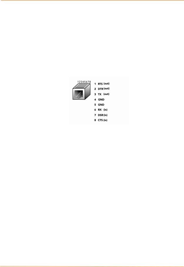
The EDS8PR has 8 serial ports, the EDS16PR has 16 serial ports, and the EDS32PR has 32 serial ports. All serial ports are configured as DTE and support baud rates up to 230,400 baud.
Figure 4-3. RJ45 Serial Port
Ethernet Port
The back panel of the EDS8/16/32PR provides an RJ45 Ethernet port. This port can connect to an Ethernet (10 Mbps) or Fast Ethernet (100 Mbps) network. The Speed LED on the back of the EDS8/16/32PR shows the connection of the attached Ethernet network. The EDS8/16/32PR can be configured to operate at a fixed Ethernet speed and duplex mode (halfor full-duplex) or auto-negotiate the connection to the Ethernet network.
LEDs
Light-emitting diodes (LEDs) on the front and back panels show status information.
Back panel. Each serial port has a Transmit and a Receive LED. The Ethernet connector has a Speed and an Activity LEDs. In addition, the back panel has a Power LED and a Status LED.
Front panel. The front panel has a green Power LED.
The table below describes the LEDs on the back of the EDS.
|
Back Panel LEDs |
|
|
LED |
Description |
Transmit (green) |
Blinking = EDS is transmitting data on the serial port. |
|
|
Receive (yellow) |
Blinking = EDS is receiving data on the serial port. |
|
|
EDS Device Servers User Guide |
27 |

|
|
4: Installation: EDS8PR, EDS16PR and EDS32PR |
||
|
|
|
|
|
|
LED |
Description |
|
|
|
Power (green) |
On = EDS is receiving power. |
||
|
|
|
|
|
|
Status (yellow) |
Fast blink = initial startup (loading OS). |
||
|
|
Slow blink (once per second) = operating system startup. |
||
|
|
On = unit has finished booting. |
||
|
|
|
|
|
|
Speed (yellow) |
On = EDS is connected to a 100 Mbps Fast Ethernet network. |
||
|
|
|
|
|
|
|
Off = EDS is connected to a 10 Mbps Ethernet network. |
||
|
|
|
|
|
|
Activity (green) |
Blink = EDS is sending data to or receiving data from the Ethernet |
||
|
|
network. |
||
|
|
|
|
|
Reset Button
The reset button is on the back of the EDS8/16/32PR, to the left of the power connector. Pressing this button for 2-to-3 seconds reboots the EDS8/16/32PR and terminates all data activity occurring on the serial and Ethernet ports.
Physically Installing the EDS8/16/32PR
Finding a Suitable Location
You can install the EDS8/16/32PR either in an EIA-standard 19-inch rack (1U tall) or as a desktop unit.
If using AC power, avoid outlets controlled by a wall switch.
Connecting the EDS8/16/32PR
All serial ports support RS-232 devices.
To connect the EDS8/16/32PR to one or more serial devices, use the following procedure:
Note: We recommend you power off the serial devices that will be connected to the EDS8/16/32PR.
1.For each serial device you want to connect, attach a CAT 5 serial cable between the EDS8/16/32PR and your serial device. For a list of cables and adapters you can use with the EDS8/16/32PR, see E: Lantronix Cables and Adapters.
2.Connect an Ethernet cable between the EDS8/16/32PR Ethernet port and your Ethernet network.
3.Insert the supplied power cord into the power connector on the back of the EDS8/16/32PR. Plug the other end into an AC wall outlet. After power-up, the selftest begins.
4.Power up all connected serial devices.
EDS Device Servers User Guide |
28 |

4: Installation: EDS8PR, EDS16PR and EDS32PR
Figure 4-4. Example of EDS16PR Connections
EDS Device Servers User Guide |
29 |

5: Getting Started
Using DeviceInstaller
The product CD included with your EDS package includes a program called DeviceInstaller. This program lets you view the properties of the EDS and launch EDS configuration methods.
Note: You can also assign an IP address and other basic network settings. For instructions, see the online Help.
Starting DeviceInstaller
Follow the prompts to install DeviceInstaller.
To run DeviceInstaller:
1.From the Windows Start menu, click StartÆPrograms, LantronixÆ DeviceInstallerÆDeviceInstaller.
2.Click the EDS folder. The list of Lantronix EDS devices available displays.
3.Expand the list by clicking the + symbol next to the icon for the desired EDS model.
4.To view the configuration of the EDS, select the unit by clicking its IP address.
Figure 5-1. Lantronix DeviceInstaller
EDS Device Servers User Guide |
30 |
Loading...