


 Loading...
UDS2100
User Guide
Part Number 900-448
Revision A September 2006

Copyright & Trademark
© 2006, Lantronix. All rights reserved. No part of the contents of this book may be transmitted or reproduced in any form or by any means without the written permission of Lantronix. Printed in the United States of America.
Ethernet is a trademark of XEROX Corporation. UNIX is a registered trademark of The Open Group. Windows 95, Windows 98, Windows 2000, and Windows NT are trademarks of Microsoft Corp. Netscape is a trademark of Netscape Communications Corporation.
Contacts
Lantronix
15353 Barranca Parkway
Irvine, CA 92618, USA
Phone: 949-453-3990
Fax: 949-453-3995
Technical Support
Online: www.lantronix.com/support
Sales Offices
For a current list of our domestic and international sales offices, go to the Lantronix Web site at http://www.lantronix.com/about/contact/index.html
Revisions
|
Date |
Rev. |
Comments |
|
|
9/06 |
A |
Initial document |
|
UDS2100 User Guide |
2 |

Contents
1: Using This Guide |
7 |
Purpose and Audience _______________________________________________ 7 Chapter Summary ___________________________________________________ 7 Additional Documentation _____________________________________________ 8
2: Introduction |
9 |
Applications ________________________________________________________ 9 Application Examples ________________________________________________ 9 Protocol Support ___________________________________________________ 11 Additional Features _________________________________________________ 11 Configuration Methods ______________________________________________ 11 Product Information Label ____________________________________________ 12
3: Getting Started |
13 |
Package Contents __________________________________________________ 13 Installing the UDS __________________________________________________ 14 Required Information________________________________________________ 15
Hardware Address ______________________________________________ 15
IP Address ____________________________________________________ 15 Assigning the IP Address: DeviceInstaller________________________________ 16
Installing DeviceInstaller __________________________________________ 16 Assigning an IP Address__________________________________________ 16 Adding the Unit to the Manage List __________________________________ 17 Accessing the UDS2100 Using DeviceInstaller ________________________ 17 Viewing the Current Configuration __________________________________ 17
Next Step _____________________________________________________ 19 Assigning the IP Address: Serial Port Login ______________________________ 20
4: Configuration Using Web Manager |
21 |
Accessing UDS2100 Using DeviceInstaller_______________________________ 21 Network Configuration _______________________________________________ 22
Automatic IP Address Configuration _________________________________ 23 Static IP Address Configuration ____________________________________ 24
Ethernet Configuration ___________________________________________ 24 Server Configuration ________________________________________________ 25 Host List Configuration ______________________________________________ 26 Channel 1 and Channel 2 Configuration _________________________________ 27
Serial Settings__________________________________________________ 27 Connection Settings - TCP ________________________________________ 30
Connection Settings - UDP ________________________________________ 33 Apply Settings _____________________________________________________ 34 Apply Factory Defaults ______________________________________________ 34
5: Configuration via Telnet or Serial Port (Setup Mode) |
35 |
Accessing Setup Mode ______________________________________________ 35 Telnet Connection_______________________________________________ 35
UDS2100 User Guide |
3 |

Serial Port Connection ___________________________________________ 36 Exiting Setup Mode _________________________________________________ 37
6: Setup Mode: Server Configuration |
38 |
Server Configuration (Option 0)________________________________________ 38 IP Address________________________________________________________ 38 Set Gateway IP Address _____________________________________________ 38 Netmask: Number of Bits for Host Part __________________________________ 39 Change Telnet Configuration Password _________________________________ 39 DHCP Name ______________________________________________________ 39
7: Setup Mode: Channel Configuration |
41 |
Channel 1 (Option 1) ________________________________________________ 41 Baudrate _________________________________________________________ 41 I/F (Interface) Mode _________________________________________________ 42 Flow_____________________________________________________________ 42 Port Number ______________________________________________________ 43 Connect Mode _____________________________________________________ 43
a)Incoming Connection __________________________________________ 45
b)Response ___________________________________________________ 45
c)Active Startup ________________________________________________ 45
d)Datagram Type _______________________________________________ 47
e)Modem Mode ________________________________________________ 48 Send the Escape Sequence (+++) in Modem Mode ________________________ 50 Auto Increment Source Port __________________________________________ 50 Remote IP Address _________________________________________________ 51 Remote Port ______________________________________________________ 51 DisConnMode _____________________________________________________ 51 Flush Mode (Buffer Flushing) _________________________________________ 52 Pack Control ______________________________________________________ 52
Packing Interval ________________________________________________ 53 Trailing Characters ______________________________________________ 53
Send Characters ________________________________________________ 53 DisConnTime (Inactivity Timeout) ______________________________________ 54 Send Characters ___________________________________________________ 54 Telnet Terminal Type________________________________________________ 54 Channel (Port) Password ____________________________________________ 54
8: Setup Mode: Advanced Settings |
55 |
Expert Settings (Option 5) ____________________________________________ 55 TCP Keepalive time in seconds ____________________________________ 55 ARP Cache timeout in seconds ____________________________________ 56 Disable Monitor Mode at bootup ____________________________________ 56 HTTP Port Number ______________________________________________ 56 MTU Size _____________________________________________________ 56 Enable alternate MAC____________________________________________ 56
Ethernet connection type _________________________________________ 56 Security Settings (Option 6)___________________________________________ 57
Disable SNMP__________________________________________________ 57 SNMP Community Name _________________________________________ 57 Disable Telnet Setup_____________________________________________ 57
UDS2100 User Guide |
4 |

Disable TFTP Firmware Update ____________________________________ 58 Disable Port 77FE (Hex) __________________________________________ 58 Disable Web Server _____________________________________________ 58 Disable Web Setup ______________________________________________ 58 Disable ECHO Ports _____________________________________________ 58
Enable Enhanced Password _______________________________________ 58 Default Settings (Option 7) ___________________________________________ 59
Channel 1 and Channel 2 Configuration Defaults_______________________ 59 Expert Settings Defaults __________________________________________ 59 Security Settings Defaults _________________________________________ 59
9: Firmware Upgrades |
61 |
Obtaining Firmware _________________________________________________ 61 Reloading Firmware ________________________________________________ 61
Using TFTP: Graphical User Interface _______________________________ 61 Using TFTP: Command Line Interface _______________________________ 62 Recovering the Firmware Using the Serial Port and DeviceInstaller_________ 62
10: Monitor Mode |
64 |
Entering Monitor Mode Using the Serial Port __________________________ 64 Entering Monitor Mode Using the Network Port ________________________ 64 Monitor Mode Commands_________________________________________ 64
11: Troubleshooting and Contact Information |
66 |
LEDs ____________________________________________________________ 66 Problems and Error Messages ________________________________________ 68 Technical Support __________________________________________________ 70
12: Connections and Pinouts |
71 |
UDS2100 Serial Ports____________________________________________ 71 Serial Connector Pinouts _________________________________________ 71 Network Port ___________________________________________________ 72 Reset Button ___________________________________________________ 72 Ethernet Connector Pinouts _______________________________________ 72 Power Plug ____________________________________________________ 72
13: Technical Specifications |
73 |
A: Alternative Ways to Assign an IP Address |
76 |
DHCP ________________________________________________________ 76 AutoIP ________________________________________________________ 76 BOOTP _______________________________________________________ 77 ARP and Telnet_________________________________________________ 77
B: Binary to Hexadecimal Conversions |
78 |
Converting Binary to Hexadecimal _____________________________________ 78 Conversion Table _______________________________________________ 78 Scientific Calculator______________________________________________ 79
C: Warranty |
80 |
|
|
UDS2100 User Guide |
5 |

D: Compliance and Disclaimer |
81 |
Index |
83 |
Figures
Figure 2-1. Serial Tunneling Example _____________________________________ 10 Figure 2-2. Direct TCP/IP or Redirector Configuration ________________________ 10 Figure 2-3. Sample Hardware Address ____________________________________ 12 Figure 3-1. UDS2100 Connected to Serial Device and Network _________________ 14 Figure 4-1. Lantronix Web Manager ______________________________________ 22 Figure 4-2. Network Settings ____________________________________________ 23 Figure 4-3. Server Settings _____________________________________________ 25 Figure 4-4. Hostlist Settings ____________________________________________ 27 Figure 4-5. Channel Serial Settings_______________________________________ 28 Figure 4-6. TCP Connection Settings _____________________________________ 30 Figure 4-7. UDP Connection Settings _____________________________________ 33 Figure 5-1. MAC Address ______________________________________________ 36 Figure 5-2. Setup Menu Options _________________________________________ 36 Figure 6-1. Network Settings ____________________________________________ 38 Figure 6-2. Change Telnet Configuration Password __________________________ 39 Figure 7-1. Serial Port Settings __________________________________________ 41 Figure 7-2. Interface Mode _____________________________________________ 42 Figure 7-3. Manual Connection Address Example ___________________________ 46 Figure 8-1. Expert Settings _____________________________________________ 55 Figure 8-2. Security Settings ____________________________________________ 57 Figure 9-1. TFTP Window ______________________________________________ 62 Figure 11-1. Diagnostic, Power, and Serial Port LEDs________________________ 67 Figure 12-1. Serial Interface ____________________________________________ 71 Figure 12-2. DB9 Male RS232 Serial DTE Connector_________________________ 71 Figure 12-3. Network Interface __________________________________________ 72
Tables
Table 1-1. Chapter Summary ___________________________________________ 7 Table 3-1. Current Configuration _________________________________________ 18 Table 6-1. BootP/DHCP/AutoIP options ___________________________________ 38 Table 6-2. Standard IP Network Netmasks _________________________________ 39 Table 7-1. Interface Mode Options _______________________________________ 42 Table 7-2. Common Interface Mode Settings _______________________________ 42 Table 7-3. Flow Control Options _________________________________________ 43 Table 7-4. Reserved Port Numbers_______________________________________ 43 Table 7-5. Connect Mode Options________________________________________ 44 Table 7-6. Modem Mode Commands _____________________________________ 50 Table 7-7. Disconnect Mode Options _____________________________________ 51 Table 7-8. Flush Mode Options __________________________________________ 52 Table 7-9. Pack Control Options _________________________________________ 53 Table 9-1. Firmware Files ______________________________________________ 61 Table 10-1. Monitor Mode Commands ____________________________________ 65 Table 11-1. UDS2100 LEDs ____________________________________________ 67 Table 11-2. Problems and Error Messages_________________________________ 68 Table 13-1. UDS2100 Technical Specifications _____________________________ 73
UDS2100 User Guide |
6 |

1: Using This Guide
Purpose and Audience
This guide provides the information needed to configure, use, and update the UDS2100 device server. It is for system administrators and those responsible for installing and maintaining the UDS.
Chapter Summary
Table 1-1. Chapter Summary |
|
|
|
Chapter |
Description |
|
|
2: Introduction |
Describes the main features of the UDS and the protocols |
|
it supports. |
|
|
3: Getting Started |
Provides information for installing your unit and getting it |
|
up and running using DeviceInstaller or a serial port |
|
connection. |
|
|
4: Configuration Using Web |
Details using the Web Manager to set parameters such as |
Manager |
port and server properties. |
|
|
5: Configuration via Telnet or |
Provides instructions for accessing Setup Mode |
Serial Port (Setup Mode) |
(command line interface) using a Telnet connection |
|
through the network or a terminal or terminal emulation |
|
program through the serial port. |
|
|
6: Setup Mode: Server |
Details the network (server) settings. |
Configuration |
|
|
|
7: Setup Mode: Channel |
Details the serial port settings. |
Configuration |
|
|
|
8: Setup Mode: Advanced |
Details expert and security settings and explains how to |
Settings |
reset the unit to factory default values. |
|
|
9: Firmware Upgrades |
Provides instructions for obtaining the latest firmware and |
|
updating the UDS. |
|
|
10: Monitor Mode |
Provides instructions for accessing and using the |
|
command line interface to monitor the network and |
|
diagnose problems. |
|
|
11: Troubleshooting and |
Describes common problems and error messages and how |
Contact Information |
to contact Lantronix Technical Support. |
|
|
12: Connections and Pinouts |
Provides descriptions and illustrations of connection |
|
hardware. |
|
|
UDS2100 User Guide |
7 |
|
|
1: Using This Guide |
|
|
|
|
|
|
Chapter |
Description |
|
|
|
|
|
|
13: Technical Specifications |
Lists technical specifications for the UDS. |
|
|
|
|
|
|
A: Alternative Ways to Assign |
Provides detailed information about using DHCP, AutoIP, |
|
|
an IP Address |
BOOTP ARP, and Telnet to assign an IP address. |
|
|
|
|
|
|
B: Binary to Hexadecimal |
Provides instructions for converting binary values to |
|
|
Conversions |
hexadecimal. |
|
|
|
|
|
Additional Documentation
The following information is available on the product CD or the Lantronix Web site (www.lantronix.com).
Document |
Description |
|
|
UDS1100/2100 Quick Start |
Provides the steps for getting the UDS2100 up and |
|
running. |
|
|
DeviceInstaller Online Help |
Provides instructions for using the Windows-based |
|
utility to configure the UDS2100 and other Lantronix |
|
device servers. |
|
|
“Live” Tutorials on the |
Explain and demonstrate assigning an IP address to |
Lantronix Web Site (English) |
the UDS and setting up the UDS and Com Port |
|
Redirector. See http://ts.lantronix.com/tutorials.html. |
|
|
Com Port Redirector Quick |
Provides information on using the Windows-based utility |
Start and Online Help |
to create a virtual com port. |
|
|
UDS2100 User Guide |
8 |

2: Introduction
The UDS2100 is a 2-port device server that provides a quick, simple, and costeffective way to bring the advantages of data accessibility and remote management to devices not currently connected to a network.
Applications
The UDS family of Device Servers allows serial devices, such as those listed below, to connect and communicate over Ethernet networks using the IP protocol family (TCP for connection-oriented stream applications and UDP for datagram applications).
Security alarms
Access control devices
Fire control panels
Time/attendance clocks and terminals
ATM machines
Data collection devices
RFID readers
Universal Power Supply (UPS) management units
Telecommunications equipment
Data display devices
Virtually any asynchronous RS-232, RS422, or RS485 device
Application Examples
Using a method called serial tunneling, the UDS encapsulates serial data into packets and transports them over Ethernet. Using two UDS units, connected by a network, virtual serial connections can extend across a facility or around the world.
UDS2100 User Guide |
9 |

2: Introduction
Figure 2-1. Serial Tunneling Example
The Com Port Redirector software included on the product CD simplifies the integration process by extending the functionality of COM-port-based Windows™ applications. Virtual COM ports, mapped to remote device servers on the network, can replace direct serial connections.
Figure 2-2. Direct TCP/IP or Redirector Configuration
Note: For step-by-step instructions on configuring the UDS for serial tunneling or for use with the Com Port Redirector, see UDS Configuration Tutorials on the Lantronix web site: www.lantronix.com/support.
UDS2100 User Guide |
10 |
2: Introduction
Protocol Support
The UDS uses the Internet Protocol (IP) for network communications and the Transmission Control Protocol (TCP) to assure that no data is lost or duplicated and that everything sent to the connection arrives correctly at the target.
Supported protocols include:
ARP, UDP, TCP, ICMP, Telnet, TFTP, AutoIP, DHCP, HTTP, and SNMP for network communications.
TCP, UDP, and Telnet for connections to the serial port. TFTP for firmware updates.
IP for addressing, routing, and data block handling over the network.
User Datagram Protocol (UDP) for typical datagram applications in which devices interact with other devices without a point-to-point connection.
Additional Features
Modem Emulation: In modem emulation mode, the UDS can replace dial-up modems. The unit accepts modem AT commands on the serial port and then establishes a network connection to the end device. This arrangement leverages network connections and bandwidth to eliminate dedicated modems and phone lines.
Built-in Web Server: The UDS includes a built-in web server for configuring the unit and displaying operating and troubleshooting information on the attached links to online support.
Configuration Methods
After installation, the UDS requires configuration. For the unit to operate correctly on a network, it must have a unique IP address on the network. There are three basic methods for logging into the UDS and assigning IP addresses and other configurable settings:
DeviceInstaller: Configure the IP address and other network settings on the UDS using a Graphical User Interface (GUI) on a PC attached to a network.
(See Assigning the IP Address: DeviceInstaller on page 16.)
Web Manager: Through a web browser, configure the UDS settings using the Lantronix Web Manager. (See 4: Configuration Using Web Manager.)
Serial and Telnet Ports: Use Setup Mode, a command line interface. There are two approaches to accessing Setup Mode: making a Telnet connection to the network port (9999) or connecting a terminal (or a PC running a terminal emulation program) to the unit’s serial port. (See 5: Configuration via Telnet or Serial Port (Setup Mode).)
UDS2100 User Guide |
11 |

2: Introduction
Product Information Label
The product information label on the underside of the unit contains the following information about your specific unit:
Bar code Serial number
Product ID (name) Product description
Hardware address (also referred to as the Ethernet or MAC address)
The first three bytes of the hardware address are fixed and read 00-20-4A, identifying the unit as a Lantronix product. The fourth, fifth, and sixth bytes are unique numbers assigned to each unit.
Figure 2-3. Sample Hardware Address
00-20-4A-14-01-18 or 00:20:4A:14:01:18
UDS2100 User Guide |
12 |

3: Getting Started
This chapter describes how to get your UDS up and running in the shortest possible time.
Package Contents
Verify and inspect the contents of the UDS2100 package using the following list. If any item is missing or damaged, contact your place of purchase immediately.
UDS2100
DB9F to DB9F Null Modem Cable (P/N 500-164)
Power supply
CD with UDS2100 User Guide and utilities (DeviceInstaller and Com Port
Redirector)
Quick Start Guide
UDS2100 User Guide |
13 |
3: Getting Started
Installing the UDS
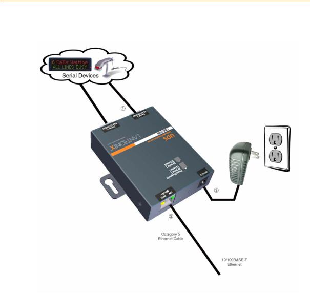
Figure 3-1. UDS2100 Connected to Serial Device and Network
To install the unit:
To install the unit, complete the following steps in order. Refer to the numbers in the previous figure.
1.Connect a serial device to your unit. See 2: Introduction for more information about what kinds of device attachments the unit supports.
2.Connect an Ethernet cable to the 10/100 port.
3.Supply power to your unit using the power supply that was included in the packaging.
Note: The required input voltage is 9-30 VDC (center +) (1.8W maximum power).
4.Supply power to the serial device.
Note: If you encounter a problem, please see 11: Troubleshooting and Contact Information.
UDS2100 User Guide |
14 |

3: Getting Started
Required Information
Before configuring the UDS, have the following information available:
Hardware Address
Take note of the unit’s hardware address (also known as the Ethernet or MAC address). It is on the product label, in the format: 00-20-4a-XX-XX-XX, where the XXs are unique numbers assigned to the product
Hardware Address: 00-20-4a-_____-_____-_____
IP Address
The UDS must have a unique IP address on your network. This address references the specific unit. By default, the unit is DHCP-enabled and automatically assigned an IP address on DHCP-enabled networks. If you are assigning a static IP address, the systems administrator generally provides the IP address, subnet mask, and gateway.
Note: The factory default IP address is 0.0.0.0 to enable DHCP, BOOTP, and AutoIP. When the units boots, it sends a DHCP broadcast to try and get an IP address. If it receives no reply from a DHCP server, the UDS tries BOOTP. If the UDS does not receive a response from BOOTP, it reverts to an AutoIP address.
IP Address: _______ _______ _______ _______
Subnet Mask: _______ _______ _______ _______
Gateway: _______ _______ _______ _______
You have several options for assigning an IP address and related network settings to your unit. This chapter provides information about using the DeviceInstaller (graphical user interface) and serial port login (command line interface) methods.
Note: For information about other methods of assigning the IP address, such as DHCP, AutoIP, ARP, and Telnet, see A: Alternative Ways to Assign an IP Address.
UDS2100 User Guide |
15 |

3: Getting Started
Assigning the IP Address: DeviceInstaller
This chapter covers the steps for getting the UDS2100 device server online and for viewing its current configuration.
Note: DeviceInstaller online Help provides more detailed information on using DeviceInstaller.
Installing DeviceInstaller
To use the DeviceInstaller utility, first install it from the product CD.
1.Insert the product CD into your CD-ROM drive. The Lantronix UDS2100 DeviceInstaller window displays.
2.If the CD does not launch automatically:
a)Click the Start button on the Task Bar and select Run.
b)Enter your CD drive letter, colon, backslash, Launch.exe (e.g.,
D:\Launch.exe).
3.Click the DeviceInstaller button.
4.Respond to the installation wizard prompts. (When prompted to select an installation type, select Typical.)
Assigning an IP Address
The unit’s IP address must be configured before it can work correctly on a network. The unit’s IP address is normally set to 0.0.0.0 at the factory. The hardware address is on the product label. The unit is DHCP enabled as the default.
To assign an IP address manually:
1. Click Start Programs Lantronix DeviceInstaller DeviceInstaller. If your PC has more than one network adapter, a message displays. Select an adapter and click OK.
Note: If the unit already has an IP address (e.g., DHCP has assigned an
IP address), click the Search icon  and select the unit from the list of Lantronix device servers on the local network.
2.Click the Assign IP icon  .
.
3.If prompted, enter the hardware address (on the product label) and click Next.
4.Select Assign a specific IP address and click Next.
5.Enter the IP address. The Subnet mask displays automatically based on the IP address; if desired, you may change it. On a local network, you can leave the Default gateway blank (all zeros). Click Next.
6.Click the Assign button and wait several seconds until a confirmation message displays. Click Finish.
UDS2100 User Guide |
16 |

3: Getting Started
7.Select the device from the main window list and select Ping from the Tools menu. The Ping Device dialog box shows the IP address of the selected unit.
8.From the Tools menu, click the Ping button. The results display in the Status window. Click the Clear Status button to clear the window so you can ping the device again.
Note: If you do not receive “Reply” messages, make sure the unit is attached to the network properly and the IP address assigned is valid for the particular network segment you are working with. If you are not sure, check with your systems administrator.
9.Click the Close button to close the dialog box and return to the main window.
Adding the Unit to the Manage List
Now add the unit to the list of similar Lantronix devices on the network so you can manage and configure it. To perform this step, click the Search icon.
DeviceInstaller locates the unit and adds it to the list. Now you can manage (configure) the unit so it works with the serial device on the network.
Accessing the UDS2100 Using DeviceInstaller
1. Click Start Programs Lantronix DeviceInstaller DeviceInstaller.
2.Click the UDS folder. The list of available Lantronix UDS2100 devices displays.
3.Expand the list of UDS2100s by clicking the + symbol next to the UDS2100 icon. Select the UDS2100 unit by clicking on its IP address to view its configuration.
Viewing the Current Configuration
DeviceInstaller provides a view of the unit's configuration.
To view the unit's current settings:
1.Follow the instructions above to locate the UDS2100.
2.In the right pane, click the Device Details tab. The current UDS2100 configuration displays:
UDS2100 User Guide |
17 |
|
|
3: Getting Started |
|
|
Table 3-1. Current Configuration |
||
|
Setting |
Description |
|
|
|
|
|
|
Name |
Configurable field. A name that identifies the UDS2100. |
|
|
|
Double-click the field, type in the value, and press Enter |
|
|
|
to complete. This name is not visible on other PCs or |
|
|
|
laptops using DeviceInstaller. |
|
|
|
|
|
|
Group |
Configurable field. A group name to categorize the |
|
|
|
UDS2100. Double-click the field, type in the value, and |
|
|
|
press Enter to complete. This group name is not visible |
|
|
|
on other PCs or laptops using DeviceInstaller. |
|
|
|
|
|
|
Comments |
Configurable field. Information about the UDS2100. |
|
|
|
Double-click the field, type in the value, and press Enter |
|
|
|
to complete. This description or comment is not visible |
|
|
|
on other PCs or laptops using DeviceInstaller. |
|
|
|
|
|
|
Device Family |
Displays the UDS2100’s device family type as UDS. |
|
|
|
|
|
|
Type |
Displays the device type as UDS2100. |
|
|
|
|
|
|
ID |
Displays the UDS2100’s ID embedded within the box. |
|
|
|
|
|
|
Hardware Address |
Displays the UDS2100’s hardware (or MAC) address. |
|
|
|
|
|
|
Firmware Version |
Displays the firmware currently installed on the UDS2100. |
|
|
|
|
|
|
Extended Firmware |
Displays the full version nomenclature of the firmware. |
|
|
Version |
|
|
|
|
|
|
|
Online Status |
Displays the UDS2100’s status as online, offline, |
|
|
|
unreachable (the UDS2100 is on a different subnet), or |
|
|
|
busy (the UDS2100 is currently performing a task). |
|
|
|
|
|
|
Telnet Enabled |
Permits Telnet sessions. |
|
|
|
|
|
|
Telnet Port |
Displays the UDS2100’s port for Telnet sessions. |
|
|
|
|
|
|
Web Enabled |
Permits configuration through Web Manager. |
|
|
|
|
|
|
Web Port |
Displays the UDS2100’s port for Web Manager |
|
|
|
configuration. |
|
|
|
|
|
|
Maximum Baud Rate |
Displays the UDS2100’s maximum baud rate. |
|
|
Supported |
Note: The UDS2100 may not be running at this rate |
|
|
|
currently. |
|
|
|
|
|
|
Firmware Upgradeable |
Displays True, indicating the UDS2100’s firmware is |
|
|
|
upgradeable as newer versions become available. |
|
|
|
|
|
|
IP Address |
Displays the UDS2100’s current IP address. To change |
|
|
|
the IP address, see Assigning an IP Address on page 16. |
|
|
|
|
|
|
Number of COB |
Displays the number of COB partitions supported. |
|
|
partitions supported |
|
|
|
|
|
|
|
Supports Dynamic IP |
Indicates whether the current IP address on the UDS2100 |
|
|
|
was set manually or assigned by DHCP. |
|
|
|
|
|
|
Subnet Mask |
Displays the UDS2100’s current subnet mask. To change |
|
|
|
the subnet mask, see Assigning an IP Address on page |
|
|
|
16. |
|
|
|
|
|
UDS2100 User Guide |
18 |
|
|
|
|
|
3: Getting Started |
|
|
|
|
|
|
|
|
|
|
|
|
Setting |
|
|
Description |
|
|
|
|
|
|
|
|||
|
|
|
|
|
|
|
|
|
|
Gateway |
Displays the UDS2100’s current gateway. To change the |
||||
|
|
|
|
|
gateway, see Assigning an IP Address on page 16. |
||
|
|
|
|
|
|||
|
|
Number of Ports |
|
Displays 2, the number of ports on the UDS2100. |
|||
|
|
|
|
|
|||
|
|
TCP Keepalive |
|
Displays the UDS2100’s TCP keepalive value. The value is |
|||
|
|
|
|
|
in the range 1-65s, and the default setting is 45. |
||
|
|
|
|
|
|||
|
|
Supports Configurable |
|
Displays False. |
|||
|
|
Pins |
|
|
|
|
|
|
|
|
|
|
|||
|
|
Supports Email Triggers |
|
Displays False. |
|||
|
|
|
|
|
|||
|
|
Supports AES Data |
|
Displays False. |
|||
|
|
Stream |
|
|
|
|
|
|
|
|
|
|
|||
|
|
Supports 485 |
|
Displays True. The UDS2100 supports the RS-485 |
|||
|
|
|
|
|
protocol. |
||
|
|
|
|
|
|||
|
|
Supports 920K Baudrate |
|
Displays True. The UDS2100 supports baud rates up to |
|||
|
|
|
|
|
920K. |
||
|
|
|
|
|
|||
|
|
Supports HTTP Server |
|
Displays True. The UDS2100 supports HTTP server. |
|||
|
|
|
|
|
|||
|
|
Supports HTTP Setup |
|
Displays True. The UDS2100 supports HTTP setup. |
|||
|
|
|
|
|
|||
|
|
Supports 230K Baud |
|
Displays True. The UDS2100 supports a baud rate of |
|||
|
|
Rate |
|
230K. |
|||
|
|
|
|
|
|||
|
|
Supports GPIO |
|
False |
|||
|
|
|
|
|
|
|
|
Next Step
You have the following options:
To configure the unit using a Web browser:
1.Click the Web Configuration tab.
2.Do one of the following:
To view the Web Manager in the current DeviceInstaller window, click the Go button.
To open the Web Manager in a web browser, click the External Browser button.
The Web Manager displays. A user and password dialog box displays.
3.By default, no user and password are configured, so just press OK.
4.Continue with 4: Configuration Using Web Manager.
Note: Alternatively, to open Web Manager, open your web browser and enter the IP address of the unit.
To configure the unit using a Telnet session:
1.Click the Telnet Configuration tab. The Setup Mode window displays.
2.Press Enter within 5 seconds.
UDS2100 User Guide |
19 |

3: Getting Started
3. Continue with step 4 in 5: Configuration via Telnet or Serial Port (Setup Mode).
Assigning the IP Address: Serial Port Login
To assign the IP address and other network settings using a serial connection:
1.Connect a console terminal or a PC running a terminal emulation program to the unit's serial port. The default serial port settings are 9600 baud, 8 bits, no parity, 1 stop bit, no flow control.
2.To enter Setup Mode, cycle the unit's power (power off and back on). After power-up, the self-test begins and the red Diagnostic LED starts blinking. You have one second to enter three lowercase x characters.
Note: The easiest way to enter Setup Mode is to hold down the x key at the terminal (or emulation) while powering up the unit.
3.Select 0 (Server Configuration) and follow the prompts until you get to
IP address.
4.Enter the new IP address, subnet mask, and gateway (if applicable).
5.Do one of the following:
Continue with 5: Configuration via Telnet or Serial Port (Setup Mode). Select 9 to save and exit Setup Mode. The unit performs a power reset.
UDS2100 User Guide |
20 |
4: Configuration Using Web Manager
You must configure the unit so it can communicate on a network with your serial device. For example, you must set the way the unit will respond to serial and network traffic, how it will handle serial packets, and when to start or close a connection.
The unit’s configuration is stored in nonvolatile memory and is retained without power. You can change the configuration at any time. The unit performs a reset after you change and store the configuration.
In this chapter, we describe how to configure the UDS2100 using Web Manager, Lantronix’s browser-based configuration tool. (For information on using Setup Mode, our command line configuration interface, see 5: Configuration via Telnet or Serial Port (Setup Mode).
Note: The examples in this section show a typical device. Your device may have different configuration options.
Accessing UDS2100 Using DeviceInstaller
Note: Make note of the hardware (MAC) address. You will need it to locate the UDS2100 using DeviceInstaller. For more information on the hardware address, see Hardware Address on page 15.
Follow the instructions on the product CD to install and run DeviceInstaller.
1. Click Start Programs Lantronix DeviceInstaller DeviceInstaller. If the PC has more than one network adapter, a message displays requesting the selection of a network adapter. Select an adapter and click OK.
2.Click the Search icon  . The list of Lantronix device servers displays in the left pane.
3.Click the UDS folder. The list of available UDS products displays.
4.Expand the list of UDS2100s by clicking the + symbol next to the UDS2100 icon.
5.Select the UDS2100 unit by clicking its hardware address.
6.In the right pane, click the Web Configuration tab.
7.To view the UDS2100’s Web Manager in the current DeviceInstaller window, click the Go button. To open the Web Manager in a web browser, click the External Browser button. The Web Manager displays.
Note: Alternatively, to open Web Manager, open your web browser and enter the IP address of the UDS2100.
UDS2100 User Guide |
21 |
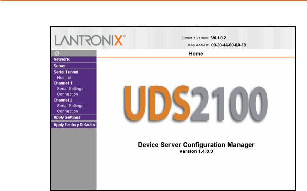
4: Configuration Using Web Manager
Figure 4-1. Lantronix Web Manager
The main menu is in the left pane of the Web Manager window.
Network Configuration
The unit’s network values display when you select Network from the main menu. The following sections describe the configurable parameters on the Network Settings page.
UDS2100 User Guide |
22 |
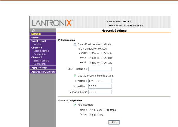
4: Configuration Using Web Manager
Figure 4-2. Network Settings
Automatic IP Address Configuration
An IP address can be assigned automatically. You then enter related network settings.
To assign an IP address automatically:
1.On the main menu, click Network.
2.Select Obtain IP address automatically.
3.Enter the following (as necessary):
BOOTP |
Select Enable to permit the Bootstrap Protocol (BOOTP) |
|
server to assign the IP address from a pool of addresses |
|
automatically. Enable is the default. |
|
|
DHCP |
Select Enable to permit the Dynamic Host Configuration |
|
Protocol (DHCP) to assign a leased IP address to the |
|
UDS2100 unit automatically. Enable is the default. |
|
|
AutoIP |
Select Enable to permit the UDS2100 to generate an IP in |
|
the 169.254.x.x address range with a Class B subnet. |
|
Enable is the default. |
|
|
DHCP Host Name |
Enter the name of the host on the network providing the |
|
IP address. |
|
|
Note: Disabling BOOTP, DHCP, and AutoIP (all three checkboxes) is not advised as the only available IP assignment method will then be ARP or serial port.
UDS2100 User Guide |
23 |

4: Configuration Using Web Manager
4.When you are finished, click the OK button.
5.On the main menu, click Apply Settings.
Static IP Address Configuration
You can manually assign an IP address to the unit and enter related network settings.
To assign an IP address manually:
1.On the main menu, click Network.
2.Select Use the following IP configuration.
3.Enter the following (as necessary):
IP Address |
If DHCP is not used to assign IP addresses, enter it |
|
manually in decimal-dot notation. The IP address must be |
|
set to a unique value in the network. |
|
|
Subnet Mask |
A subnet mask defines the number of bits taken from the |
|
IP address that are assigned for the host part. |
|
|
Default Gateway |
The gateway address, or router, allows communication to |
|
other LAN segments. The gateway address should be the |
|
IP address of the router connected to the same LAN |
|
segment as the unit. The gateway address must be within |
|
the local network. |
|
|
4.When you are finished, click the OK button.
5.On the main menu, click Apply Settings.
Ethernet Configuration
You must specify the speed and direction of data transmission.
To specify how data will be transmitted:
1.On the main menu, click Network.
2.Enter the following (as necessary):
Auto Negotiate |
With this option, the Ethernet port auto-negotiates the |
|
speed and duplex with the hardware endpoint to which it |
|
is connected. This is the default. |
|
If this option is not selected, complete the fields that |
|
become available: |
|
Speed: The speed of data transmission. The default |
|
setting is 100 Mbps. |
|
Duplex: The direction of data transmission. The |
|
default setting is Full. |
|
|
3.When you are finished, click the OK button.
4.On the main menu, click Apply Settings.
UDS2100 User Guide |
24 |
4: Configuration Using Web Manager
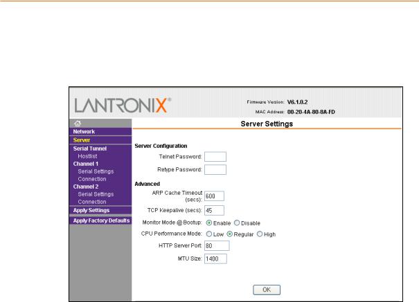
Server Configuration
The unit’s server values display when you select Server from the main menu. The following sections describe the configurable parameters on the Server Settings page.
Figure 4-3. Server Settings
To configure the UDS2100’s device server settings:
1.On the main menu, click Server.
2.Configure or modify the following fields:
Server Configuration
Telnet Password |
Enter the password required for Telnet access. |
|
|
Retype Password |
Re-enter the password required for Telnet access. |
|
|
Advanced
ARP Cache Timeout |
When the unit communicates with another device on the |
(secs) |
network, it adds an entry into its ARP table. ARP Cache |
|
timeout defines the number of seconds (1-600) before it |
|
refreshes this table. |
|
|
TCP Keepalive (secs) |
TCP Keepalive time defines how many seconds the unit |
|
waits during network failure or network interruption |
|
before checking its status. If the unit does not receive a |
|
response, it drops that connection. Enter a value between |
|
0 and 65 seconds. 0 disables keepalive. The default |
|
setting is 45. |
|
|
UDS2100 User Guide |
25 |
Loading...