


GAS FULL SIZE COMPUTERIZED CONVECTION OVEN
Enviro-STAR (GCSF-ES)
Service Manual
2M-W1345 Rev. - 08/01/08
Service Manual for Enviro-Star GCSF-ES
These symbols are intended to alert the user to the presence of important operating and maintenance instructions in this manual.
IMPORTANT FOR YOUR SAFETY
THIS MANUAL HAS BEEN PREPARED FOR PERSONNEL QUALIFIED TO INSTALL GAS EQUIPMENT, WHO SHOULD PERFORM THE INITIAL FIELD START-UP AND ADJUSTMENTS OF THE EQUIPMENT COVERED BY THIS MANUAL.
POST IN A PROMINENT LOCATION
THE INSTRUCTIONS TO BE FOLLOWED IN THE EVENT THE SMELL OF GAS IS DETECTED. THIS INFORMATION CAN BE OBTAINED FROM THE LOCAL GAS SUPPLIER.
 WARNING!
IN THE EVENT OF A POWER FAILURE, DO NOT ATTEMPT TO OPERATE THIS DEVICE.
 WARNING!
IN THE EVENT A GAS ODOR IS DETECTED, SHUT DOWN UNIT AT THE MAIN SHUTOFF VALVE AND CONTACT THE LOCAL GAS COMPANY OR GAS SUPPLIER FOR SERVICE.
FOR YOUR SAFETY
DO NOT STORE OR USE GASOLINE OR OTHER FLAMMABLE VAPORS OR LIQUIDS IN THE VICINITY OF THIS OR ANY OTHER APPLIANCE.
 WARNING!
IMPROPER INSTALLATION, ADJUSTMENT, ALTERATION, SERVICE, OR MAINTENANCE
CAN CAUSE PROPERTY DAMAGE, INJURY, OR DEATH.
READ THE INSTALLATION, OPERATING, AND MAINTENANCE INSTRUCTIONS
THOROUGHLY BEFORE OPERATING THIS EQUIPMENT.
 WARNING
TO REDUCE THE RISK OF ELECTRICAL SHOCK, DO NOT REMOVE THE CONTROL PANEL. THERE ARE NO USER-SERVICABLE PARTS INSIDE. REPAIRS SHOULD BE MADE BY AUTHORIZED SERVICE PERSONNEL ONLY.
NOTICE
Using any part other than genuine Lang factory supplied parts relieves the manufacturer of all liability. Lang reserves the right to change specifications and product design without notice. Such revisions do not entitle the buyer to correspondingchanges,improvements,additions,orreplacementsforpreviouslypurchasedequipment.
Due to periodic changes in designs, methods, procedures, policies, and regulations, the specifications contained in this document are subject to change without notice. While Lang Manufacturing exercises good faith efforts to provide information that is accurate, we are not responsible for errors or omissions in information provided or conclusions reached as a result of using the specifications. By using the information provided, the user assumes all risks in connection with such use.
SM-2 |
Lang A Division of Star Mfg. Int'l Inc. |

Service Manual for Enviro-Star GCSF-ES
TABLE OF CONTENTS
SAFETYPRECAUTIONS ............................................................................................................... |
2 |
INTRODUCTION .............................................................................................................................. |
5 |
GENERAL ............................................................................................................................... |
5 |
INSTALLATION........................................................................................................................ |
5 |
OPERATION ........................................................................................................................... |
5 |
CLEANING .............................................................................................................................. |
5 |
TOOLS .................................................................................................................................... |
5 |
SPECIFICATIONS ................................................................................................................... |
5 |
UTILITYREQUIREMENTS ....................................................................................................... |
5 |
WATER QUALITY REQUIREMENTS ...................................................................................... |
5 |
DESCRIPTION ................................................................................................................................ |
6 |
CONVECTION OVEN BASICS ....................................................................................................... |
6 |
COMPONENTOPERATION ........................................................................................................... |
6 |
Electrical Power Circuit ................................................................................................... |
6 |
Thermostat Operation ..................................................................................................... |
6 |
Gas Flow and Ignition ..................................................................................................... |
7 |
Ignition System ............................................................................................................... |
7 |
Specifications ........................................................................................................... |
7 |
Fan Operation ................................................................................................................. |
9 |
Door Switch Operation .................................................................................................. |
10 |
Oven Lights................................................................................................................... |
11 |
Water (Steam) Applications .......................................................................................... |
11 |
Burnt Gas Exhaust ....................................................................................................... |
11 |
Draft Inducer Operation .......................................................................................... |
12 |
CONTROLS .................................................................................................................................. |
13 |
Using Backup Controls ................................................................................................. |
14 |
Initial Power ON Test .................................................................................................... |
14 |
Water/Steam Test ........................................................................................................ |
15 |
Operating Sequence ..................................................................................................... |
15 |
MAINTENANCE ............................................................................................................................ |
17 |
OvenCleaning ....................................................................................................................... |
17 |
Stainless Steel Care ............................................................................................................. |
18 |
Cleaning ................................................................................................................................ |
18 |
Preserving & Restoration ....................................................................................................... |
18 |
Heat Tint ............................................................................................................................... |
18 |
Lockout/Tagout Procedures................................................................................................... |
18 |
Electrical Lockout/Tagout ...................................................................................................... |
18 |
Gas Lockout/Tagout .............................................................................................................. |
19 |
Gas Leak Test ....................................................................................................................... |
19 |
Electronics Access ............................................................................................................... |
19 |
Main Power Fuse Replacement ............................................................................................. |
20 |
Circuit Board Replacement.................................................................................................... |
21 |
Lang A Division of Star Mfg. Int'l Inc. |
SM-3 |

Service Manual for Enviro-Star GCSF-ES
TABLE OF CONTENTS (continued)
Power Transformer Replacement ........................................................................................... |
22 |
BeeperRemoval .................................................................................................................... |
23 |
Relays ................................................................................................................................... |
23 |
Relay Operation ............................................................................................................ |
24 |
Relay Replacement....................................................................................................... |
24 |
Ignition Controller Replacement ............................................................................................. |
25 |
Right Side Panel Removal ..................................................................................................... |
25 |
Temperature Sensor Replacement ........................................................................................ |
26 |
Fan Motor Starter Capacitor Replacement ............................................................................. |
26 |
Internal Access ..................................................................................................................... |
27 |
Fan Blade Removal ............................................................................................................... |
27 |
Fan Motor Replacement ........................................................................................................ |
28 |
Motor Small Fan Blade Installation ........................................................................................ |
29 |
Burner Area Access .............................................................................................................. |
29 |
Igniter Replacement............................................................................................................... |
30 |
Flame Sensor Replacement .................................................................................................. |
30 |
Burner Replacement .............................................................................................................. |
30 |
Heat Exchanger Replacement ............................................................................................... |
31 |
Steamer Assembly Replacement .......................................................................................... |
32 |
Over-TemperatureSwitchReplacement ................................................................................. |
33 |
Main Gas Solenoid Replacement .......................................................................................... |
33 |
Manual Gas Valve Replacement............................................................................................ |
34 |
Water Solenoid Replacement ................................................................................................ |
35 |
Thermostat Replacement (Backup Controls) ......................................................................... |
36 |
Steam Switch Replacement (Backup Controls) ..................................................................... |
37 |
Manual/Backup Switch Replacement (Backup Controls) ....................................................... |
38 |
Oven Light Bulb Replacement ............................................................................................... |
38 |
Light Fixture Replacement .................................................................................................... |
39 |
TopHingeCoverRemoval ...................................................................................................... |
39 |
Bottom Hinge Cover Removal ................................................................................................ |
40 |
Left Oven Door Removal ........................................................................................................ |
40 |
Door Switch Removal ............................................................................................................ |
41 |
Right Oven Door Removal ...................................................................................................... |
41 |
TROUBLESHOOTING ......................................................................................................... |
43 |
OVEN PROBLEMS ............................................................................................................... |
43 |
IGNITION CONTROL MODULE PROBLEMS ....................................................................... |
49 |
Flame Sensor Current Test .......................................................................................... |
49 |
ILLUSTRATED PARTS LISTING ................................................................................................. |
51 |
ENVIROSTAR EXPLODED VIEW DRAWINGS .................................................................... |
51 |
ENVIROSTAR PARTS REFERENCE ................................................................................... |
56 |
ENVIROSTAR WIRING DIAGRAMS..................................................................................... |
62 |
CALIFORNIAREGULATIONS ....................................................................................................... |
63 |
SM-4 |
Lang A Division of Star Mfg. Int'l Inc. |
Service Manual for Enviro-Star GCSF-ES
INTRODUCTION
GENERAL |
-IMPORTANT- |
Lang Gas Convection Ovens are manufactured for use with the type of gas indicated on the data plate (natural gas or propane). Variations exist between models. This manual details typical servicing procedures that would apply to most, but not all, of the listed models.
INSTALLATION
Refer to the Installation and Operation Manual.
OPERATION
Refer to the Installation and Operation Manual.
CLEANING
Refer to the Installation and Operation Manual.
TOOLS
•Standard set of hand tools
•Gas leak detection equipment
•Gas pressure manometer
WATER QUALITY REQUIREMENTS
Water line pressure and quality MUST meet the Lang Manufacturing Specifications listed below.
Contact your local water equipment system provider to assist you in determining your specific water quality, or contact Lang Technical Support for assistance, 1-800-807-9054.
LOCAL WATER CONDITIONS MAY DAMAGE LANG EQUIPMENT. FAILURE TO PROPERLY TREAT WATER MAY RESULT IN DAMAGE AND MAY VOID SOME OR ALL OF THE WARRANTY.
WATERSPECIFICATIONS:Aftertreatment,thewater must continuously be within the following parameters:
Cold Water
Minimum GPH |
3 |
|
|
PSI |
20 to 80 |
|
|
PH |
6.8 to 7.6 |
|
|
Hardness |
2 to 4 grains/gallon |
|
|
Total Dissolved Solids |
<100 PPM |
|
|
Conductivity |
<1/500,000 Ohms/in. |
|
|
Maximum Salinity Ion Content |
|
|
|
Chloramines |
<0.5 PPM |
|
|
Chlorine |
<0.5 PPM |
|
|
Chlorides |
<30 PPM |
|
|
Copper |
<0.05 PPM |
|
|
Iron |
<0.1 PPM |
|
|
Manganese |
<0.05 PPM |
|
|
Sulfates |
<40 PPM |
|
|
SPECIFICATIONS
Model |
Height × Width x Depth |
Clearance From |
Weight |
|
Freight |
|
|
|
Combustible Surfaces |
Installed |
Shipping |
Class |
|
|
|
|
|
|
|
|
GCSF-1 |
36″ × 40″ × 40″ |
Side:0″, Back:1″, Floor:4″ |
555 lbs. |
620 lbs. |
70 |
|
|
(91.4cm × 101.6cm × 101.6cm) |
|
(252 kg) |
(281 |
kg) |
|
|
|
|
|
|
|
|
GCSF-2 |
74″ × 40.4″ × 40″ |
Side:0″, Back:1″, Floor:4″ |
1110 lbs. |
1240 |
lbs. |
70 |
|
(188cm × 102.6cm × 101.6cm) |
|
(503 kg) |
(562 |
kg) |
|
|
|
|
|
|
|
|
UTILITY REQUIREMENTS
Model |
Voltage |
|
Total kW |
Phase |
Amps/Line |
Total Gas Req. |
|
|
|
|
|
|
|
GCSF-1 |
120V/60Hz |
|
0.7 |
1 |
5.8 |
1/2" NPT, 60,000 BTU/hr |
|
|
|
|
|
|
|
GCSF-2 |
120V/60Hz |
|
1.4 |
1 |
11.6 |
1/2" NPT, 120,000 BTU/hr |
|
|
|
|
|
|
|
|
|
|
|
|
|
|
Lang A Division of Star Mfg. Int'l Inc. |
|
|
|
SM-5 |
||

Service Manual for Enviro-Star GCSF-ES
DESCRIPTION
CONVECTION OVEN BASICS
A convection oven is an electro-mechanical, sealedtype of oven in which the combustion products are separated from the air inside the oven. Heated air is circulated by a fan into the oven and over the food product, removing a thin layer of moisture from the food and allowing heat to penetrate.
This method requires shorter cooking times at lower temperatures and produces consistent results, which may vary due to differences in preparation rather than in oven operation.
Steam in the cooking process prevents the removal of all the moisture during baking and produces a better product. And when applied to bread dough during the first five minutes, it allows yeast to work longer producing better spring and volume and a moist, flexible outer surface. Once the outside layer of dough sets, gases in the loaf no longer expand to increase loaf size.
Steaming bread dough as it bakes gelatinizes starch on the outer layer and prevents the crust from cracking. However, too much steam results in an undesirable crust. During the last stages of baking, a dry oven is needed to produce a crisp, brown crust.
Times and temperatures may vary due to factors such as food quality and quantity, type of pan and thermostat calibration. Differences in altitude will also affect cooking times and temperatures.
Time & Temperature Conversion: To convert standard oven recipes for use in a convection oven, reduce cooking temperature by 25° F – 75° F and the time by 25% – 35%.
Fan Speeds: The convection fan can be set for HI or LOW speed. Most baking is done on HI, but delicate products (i.e., Meringue pie) require a LOW fan setting.
COMPONENT OPERATION
Electrical Power Circuit
The operating voltage (120 VAC) is routed from the power source to a terminal block.
NOTICE: See the wiring diagrams in the Troubleshooting section.
The AC line is connected through a 15 Amp fuse (F7) to a contact on the motor relay (MR2), interior light relay (LR1), and the primary winding of a stepdown transformer (T1).
The transformer provides 24 VAC through the circuit board to control the oven electrical components.
Thermostat Operation
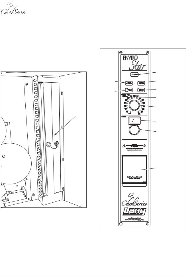
The thermostat maintains oven temperature at the desired setting. A sensor (Figure 1) mounted inside the oven monitors oven temperature. The unit is equipped with both:
•a mechanical thermostat
•a programmable temperature controller.
Oven Sensor |
Figure 1: Oven Sensor
When the operator selects a temperature setting or the product to bake, the oven is heated until the temperature reaches the selected setting. The controls circuit monitors the temperature sensor and activates the ignition control module to ignite the burner when heat is required.
SM-6 |
Lang A Division of Star Mfg. Int'l Inc. |
Service Manual for Enviro-Star GCSF-ES
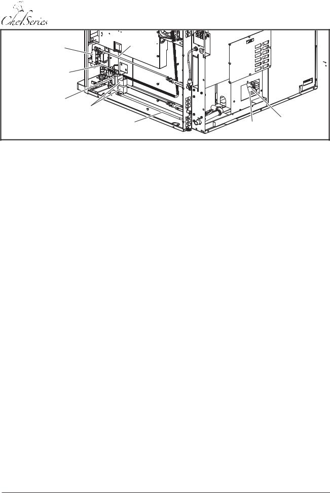
Manual Gas |
Gas Inlet |
|
||
Valve |
|
|
Line |
|
Intermediate |
|
|
|
|
Gas Line |
|
|
|
|
Main Gas |
|
|
|
|
Valve |
Solenoid |
|
|
|
|
|
|
|
|
|
Valves |
|
|
|
|
|
Burner Gas |
|
Igniter & |
|
|
Line |
Burner |
Flame |
|
|
|
|
Sensor |
Figure 2: Gas Flow Diagram
Gas Flow and Ignition |
SPECIFICATIONS: |
Natural gas is supplied through the manual gas valve (Figure 2) to the main gas solenoid. When the temperature is selected the ignition control module activates the igniter and opens the gas solenoid. Gas flows to the burner and the igniter lights the flame. The ignition control module monitors the flame sensor to determine if the burner is on. If the burner does not ignite, the solenoid valve closes shutting off gas flow to the oven.
Ignition System
The igniter module controls ignition of the burner gas. The module monitors burner ignition, heat and shut down.
Fenwal 35-66 Series Igniter Module
INPUT POWER |
Control: 18 to 30 |
Voltage |
|
|
VAC 50/60 HzLine: |
|
24 VAC |
Current |
300 MA @ 24 VAC |
|
with fan and gas |
|
valve relay energized |
|
|
OUTPUT POWER |
|
Gas Valve |
2.0A max @ 24 VAC |
|
|
OPERATINGTEMPERATURE |
-40°F to +175°F |
|
(-40°C to +80°C) |
|
|
FLAME SENSITIVITY |
0.7 micro amps |
|
(minimum) |
|
|
IGNITER |
24 VAC |
|
|
Trail for Ignition |
7 Seconds |
|
|
Inter-Purge |
15 Seconds |
|
|
Pre-Purge |
15 Seconds |
|
|
Tries for Ignition |
3 Tries with 1 Hour |
|
Automatic Reset |
|
|
Post Purge |
None |
|
|
Options |
None |
|
|
NOTE: Follow the wiring diagram and gas flow chart to better understand the ignition description.
Lang A Division of Star Mfg. Int'l Inc. |
SM-7 |
Service Manual for Enviro-Star GCSF-ES
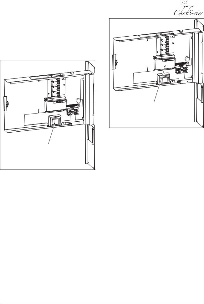
The oven ignition and control system operates on 120 and 24 VAC. When the power switch is placed in the ON position, 120 VAC is routed through fuse F7 (15A). The voltage from the fuse is routed to one side (incoming) of a 24 VAC transformer (Figure 3). The other side of the transformer (incoming) is connected to a neutral input.
Transformer |
Figure 3: Transformer
The transformer converts the 120 VAC to 24 VAC and routes the 24 VAC through the outgoing side through a back-up switch, a back-up thermostat switch and an over-temperature switch to the ignition controller pin W.
The ignition control module (Figure 4) operates on 24 VAC at pin W provided by the transformer. The module controls the main gas solenoid and the igniter.
Ignition |
Controller |
Figure 4: Ignition Control Module
When the power switch is placed in the ON position and a temperature is selected using the temperature knob a call for heat is generated in the controller.
•The controller performs a self check routine.
•The diagnostic LED flashes for one second.
•A safety timing sequence begins.
•The controller performs a 15-second pre-purge of the system.
•The controller must detect that the air switch is working properly, before it energizes the igniter and the surface of the igniter tip heats up.
•The main gas valve solenoids open allowing gas to flow to the burner.
•The gas in the burner is ignited by the igniter tip.
A TFI (trail for ignition) period checks the flame sensor for evidence of a flame at the burner. If flame does not ignite within 7-seconds the control module closes the main gas valve solenoids and gas stops flowing to the burner.
When a flame is detected, voltage to the igniter stops and the igniter cools. The thermostat, pressure switch and burner flame are monitored for proper operation. When the selected temperature is reached voltage stops flowing to the main gas valve solenoids (Figure 5) and gas stops flowing to the burner.
SM-8 |
Lang A Division of Star Mfg. Int'l Inc. |

Service Manual for Enviro-Star GCSF-ES
./4% 3EE THE TROUBLESHOOTING SECTION FOR INSTRUCTIONS ON PERFORMINGA FLAME SENSOR CURRENT CHECK
Figure 5: Igniter Controller Diagram
If flame is not detected during the TFI, the main gas valve solenoids close and a 15-second inter-purge delay starts. The control will attempt two additional TFI periods before locking out. In lockout the main gas valve solenoids will be locked out immediately. The controller will reset after one hour if the thermostat is still calling for heat. A new TFI sequence will begin.
NOTE: If locking out occurs, a manual reset must be performed by resetting the thermostat or removing 24 VAC (turn off the power switch) for a period of 5-seconds.
The following table lists the igniter terminals and functions.
NOTE: See the Troubleshooting section for instructions on performing a flame sensor current check.
Igniter Module Terminal Uses (Figure 5)
S1 |
Igniter Output – 24 VAC |
L1 |
24 VAC Input |
L2 |
Not Used |
S2 |
Flame Sensor Input |
PS |
Air Proving Switch |
W |
Thermostat Input |
MV1 |
Main Gas Valve Solenoids Output |
GND |
Ground Input |
F1 |
120 VAC Input |
F2 |
120 VAC Fan Drive Output |
FC |
Not Used |
R |
24V Hot to Transformer |
|
|
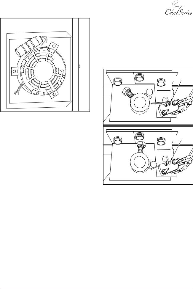
Fan Operation
The fan switch has two settings: HI and LOW. The fan is mounted inside the oven and must be ON when the oven is in operation. The main burner heats the oven through the burner box. The main burner flames do not come into contact with the air inside the oven. The fan circulates the air inside the oven over the lower surface and maintains a constant, even temperature. The motor control reverses the direction of the fan periodically to provide consistent baking operation.
Lang A Division of Star Mfg. Int'l Inc. |
SM-9 |
Service Manual for Enviro-Star GCSF-ES
Figure 6: Fan Motor Connections
The fan motor (Figure 6) operates on 120 VAC. Three relays operate on 24 VAC control motor.
The relays function as follows:
•Motor relay 1 (MR1) ON/OFF controls fan rotation by reversing the phase of the motor windings.
•Motor relay 2 (MR2) ON/OFF controls motor operation by routing 120 VAC to the fan motor.
•Motor relay 3 (MR3) ON/OFF controls fan speed by routing 120 VAC to the motor windings.
Door Switch Operation
When the oven door is closed, the door switch (Figure 7) grounds four motor relays: MR2, the ignition control module, the gas solenoid, and the igniter. When the door is open, the ground is removed and the fan motor and gas to the burner shuts off. When the door is open, the ignition control module and igniter cannot operate.
Door Switch |
DOOR OPEN |
Door Switch |
DOOR CLOSED |
Figure 7: Door Open/Closed
SM-10 |
Lang A Division of Star Mfg. Int'l Inc. |
Oven Lights
Light relay (LR1) routes voltage to one side of the four oven lights (Figure 8). The other side of the lights is connected to a neutral. When the controller applies 24 VAC to the light relay, 120 VAC is routed to the oven lights, illuminating the oven cooking area.
2YHQ /LJKWV |
Figure 8: Oven Lights
|
Water |
|
Outlet |
|
Line |
Water |
|
Solenoid |
|
Water Inlet |
|
Line |
|
Water Stall |
Drain |
|
Figure 9: Water Flow Diagram
Service Manual for Enviro-Star GCSF-ES
Water (Steam) Applications
When steam is required for the baking process, the controller activates the water solenoid (SV1) (Figure 9). Water is passed through the water stall (Figure 10) and heated to produce steam. The steam fills the cooking area. The water system has a 3/8″ inlet line and a 3/8″ supply line to the water stall. The water stall drain is 3/4″ allowing excess water to drain quickly from the water stall.
6WHDPHU |
$VVHPEO\ |
Figure 10: Steamer Assembly (Water Stall)
Burnt Gas Exhaust
When natural gas is burned in the appliance, the burnt gases must be vented away from the appliance. The gases are exhausted out a vent and through a flue (chimney or exhaust vent). There are numerous exhaust/vent systems available to carry the exhaust gases away from the appliance and work area.
 WARNING
BURNINGNATURALGASPRODUCESEXHAUST GASES THAT CONTAIN CARBON MONOXIDE. CARBON MONOXIDE IS A DEADLY GAS THAT KILLS. ENSURE THAT APPLIANCE EXHAUST VENTS, FLUES AND CHIMNEYS ARE INSTALLEDANDSERVICEDBYPROFESSIONAL INSTALLATION PERSONNEL AND ARE ADEQUATE FOR THE APPLIANCE BEING INSTALLED.
Lang A Division of Star Mfg. Int'l Inc. |
SM-11 |
Service Manual for Enviro-Star GCSF-ES
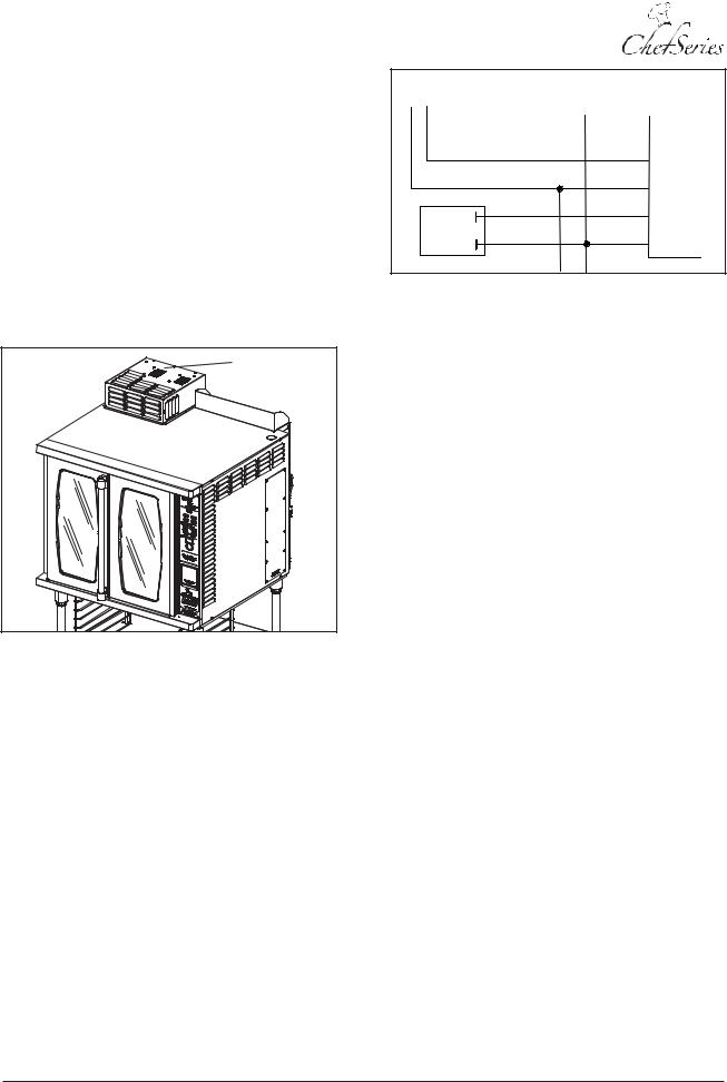
A negative pressure in the appliance allows the exhaust gases to flow up the flue. The flue helps generate air flow around the burner, allowing the burner to burn the gas more efficiently. A draft inducer (Figure 11) provides air to the burner and helps exhaust the burnt gasses.
Draft Inducer Operation
The Draft Inducer is a device mounted on the top of the oven over the exhaust vent. It provides secondary air to the burners by creating a draft. The operation of the Draft Inducer is controlled by the Ignition Control.
Draft Inducer |
Figure 11: Draft Inducer
NOTE: See the wiring diagram for wire routing for the draft inducer.
The draft inducer uses a proving switch to ensure proper air flow when the burner is in operation. The switch is mounted between the controller W terminal and the PS terminal. An internal controller switch (Figure 12) between the PS and MV1 terminals, routes voltage to the main gas valve. If the internal switch is open, the main gas valve solenoid will not open to allow gas flow to the burner.
NOTE: In a description of the draft inducer, the pressure switch is often referred to as a proving switch. The terms mean the same thing and both refer to the switch monitoring the draft inducer air flow.
TO AIR PROVING |
|
|
|
SWITCH |
|
|
|
|
|
54 |
PS |
|
37 |
37 |
W |
GAS |
55 |
55 |
MV1 |
VALVE |
|
|
GND |
|
34 |
34 |
|
Figure 12: Igniter Controller Internal Switch
During oven operation, combustion air flow is monitored by the proving switch (pressure switch). If the switch contacts remain closed for 30-seconds during ignition sequence without an output signal to the draft fan an airflow fault will be generated. If the pressure switch (proving switch) contacts open during a call for heat operation, the controller (Figure 12) will begin a pre-purge period and a trail for ignition sequence.
If the pressure switch (proving switch) contacts remain open for 30-seconds after draft inducer fan output (F1 and F2) begins, an airflow fault will be signaled and the fan will remain ON. If the pressure contacts open later during a call for heat, the controller will begin a pre-purge period and the trail for ignition sequence.
If the airflow signal (PS) is lost while the burner is firing, the controller will immediately de-energize the main gas valve solenoid and an airflow fault will be displayed. The controller will continue to monitor the proving switch (pressure switch) input waiting for airflow to return. When airflow is detected, a trail for ignition sequence will begin, followed by a prepurge period. If airflow does not return, the controller will enter a lockout condition and the draft inducer fan will shut OFF.
During normal sequence, if a flame signal occurs due to the main gas valve solenoid not closing all the way, the controller will energize the draft inducer fan. If the gas valve solenoid closes, the controller will shut off the draft inducer fan.
SM-12 |
Lang A Division of Star Mfg. Int'l Inc. |
Service Manual for Enviro-Star GCSF-ES
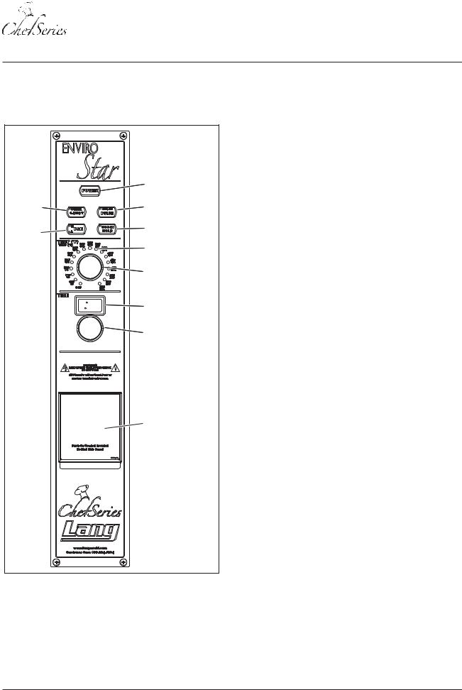
CONTROLS
The electronic control panel (Figure 13) is used to control oven operation. The unit also has manual backup controls.
|
Power |
|
1-Shot |
Pulse Steam |
|
Steam |
||
|
||
Fan |
COOK-N-HOLD |
|
HI/LOW |
LED Temp |
|
|
||
|
Indicator |
|
|
Temp Knob |
|
|
LED Timer |
|
|
Screen |
|
|
Timer Knob |
BACKUP
CONTROL
ACCESS DOOR
Figure 13: Electronic Control Panel
Electronic Control Panel (Figure 13)
POWER:
•ON/OFF button
•When pressed ON, interior lights and panel indicators turn on
•When pressed OFF, interior lights and panel indicators turn off and the fan remains ON until the oven cools down to 250° F
FAN:
•ON/OFF Switch
•Has two operating speeds: L=LOW & H=HI
•Must be turned on during operation
•During operation, the fan will reverse directions periodically to maintain consistent condition
LED TEMPERATURE INDICATOR:
•Displays oven temperature
•ON indicates oven at set point
•Blinkswithacallforheatorcoolingtotemperature
TEMPERATURE KNOB:
•Used to set oven temperature
•Dial to desired temperature
TIMER SCREEN:
•LED digital display
•Displays time remaining in cooking cycle
•Displays time selection for Steam Pulse
•Displays time selection for Steam 1- Shot time
TIMER KNOB:
•Sets cooking time
•Sets Steam Pulse time
•Sets Steam 1-Shot time
COOK/HOLD:
•Activated when cooking cycle stops and a beeper will sound 5 times
•Beeper will sound 5 times
•COOK/HOLD light will turn OFF
•Oven temperature will drop to 150° F
•Temperature will remain at 150° F until operator chooses a new cooking cycle or turns the oven OFF
Lang A Division of Star Mfg. Int'l Inc. |
SM-13 |
Service Manual for Enviro-Star GCSF-ES
1-SHOT STEAM:
•Provides a 1 – 20 second single–shot of steam to the cooking chamber
•Adjustbyholdingdownthebuttonwhileturningthe TIMERKNOBuntilthedesiredtimeisdisplayedon the LED TIMER SCREEN (Figure 13)
PULSE STEAM:
•Sends a 1-second shot of steam to the cooking chamber
•Adjust time from 1 – 120 seconds by holding down the button and turning the TIMER KNOB until the desired time is displayed on the LED TIMER SCREEN
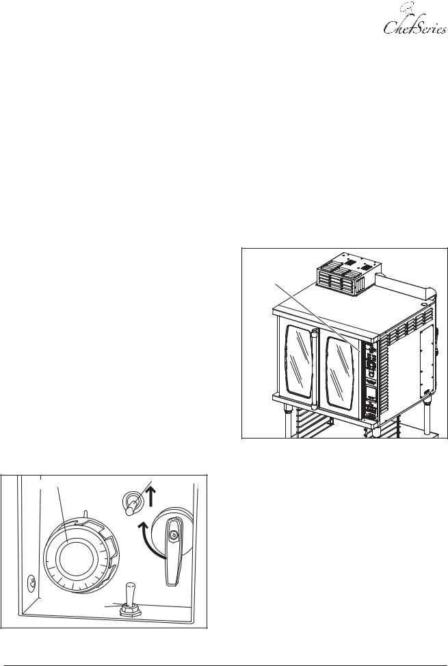
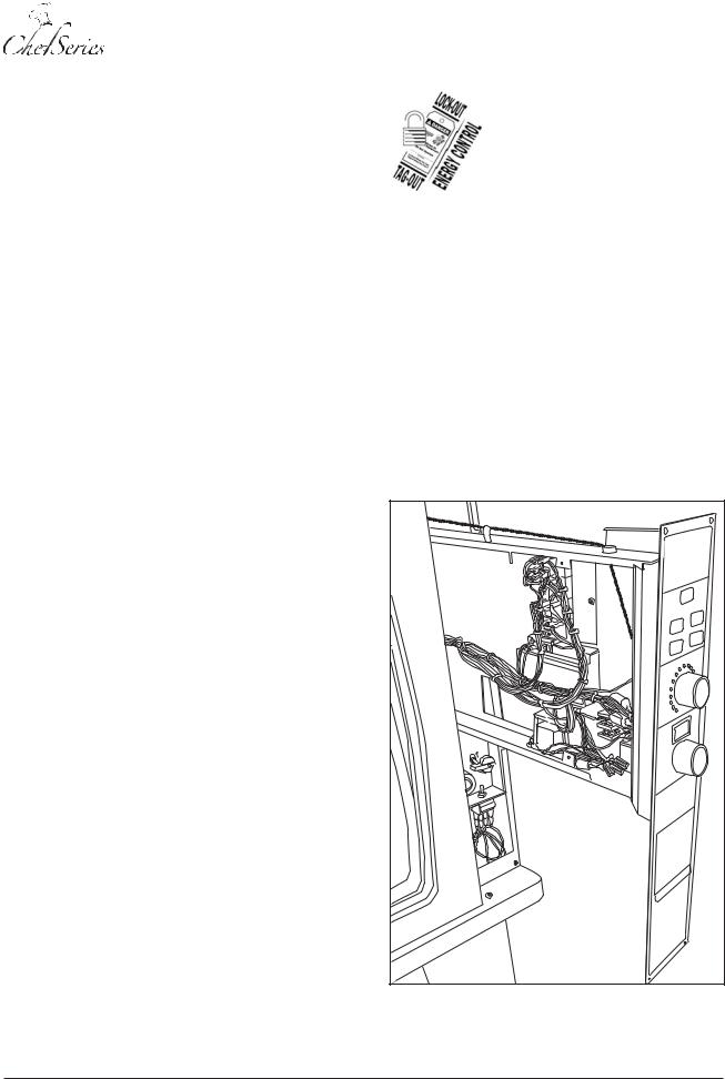
Using Backup Controls
The EnviroSTAR oven is designed with a set of backup controls that can be used manually instead of using the electronic oven controls. These controls (Figure 14) are mounted behind a door below the oven control panel (Figure 13). Controls include the BACKUP/MANUAL switch, a TEMPERATURE knob and a STEAM switch.
TheBACKUP/MANUALswitchoverridestheelectronic controls and activates the backup controls. The TEMPERATURE knob controls the temperature. The STEAM toggle switch controls the steam. In this mode, the fan will operate at HI speed only.
The Backup mode does not use the energy-saving option and does not allow the fan to operate at Low speed or reverse direction.
To use the backup controls, place the BACKUP/ MANUAL switch in the BACKUP position.
Temperature Knob |
STEAM |
Steam Switch |
|||
|
|||||
|
|
|
|
|
|
|
|
|
TEMP |
|
|
|
|
|
OFF |
G |
|
|
|
|
|
A |
|
|
|
|
|
S |
|
|
|
|
450 |
S |
|
|
|
|
|
H |
|
|
|
|
|
U |
|
|
|
|
400 |
T |
|
0 |
|
|
O |
|
|
0 |
|
|
F |
||
1 |
|
|
|
|
F |
150 |
|
|
350 |
|
|
|
0 |
|
300 |
|
|
|
|
|
|
|
|
|
0 |
|
|
|
|
|
|
2 |
250 |
|
|
|
|
|
|
|
|
Backup / Electronic |
|
|
|||
Controls Switch |
|
|
|||
Figure 14: Backup Controls
Initial Power ON Test
Follow these steps to verify the operation and temperature control of the oven:
•Press the POWER button ON and verify that the interior and panel lights turn on.
•Set the temperature to 300°F and verify that the TEMP INDICATOR light is blinking.
•Verify that the oven reaches the set point and signals Ready with an audible tone within 12 minutes (starting with a cold oven).
•Set the timer to 10 minutes and verify that the fan stops and reverses direction after approximately 108 seconds. (A full reversing cycle takes 120 seconds.)
Door Switch |
Figure 15: Door Switch Location
•Open the oven door (Figure 15) and verify that the fan and TIMER stop then restart when the door is closed.
•Turn both the TIMER KNOB and TEMP KNOB to zero.
•Confirm that the fan stays on until the temperature drops below 250°F.
SM-14 |
Lang A Division of Star Mfg. Int'l Inc. |
Water/Steam Test
Follow these steps to verify the water and steam operation of the oven:
1.Identify the water purification system used.
2.Flush the water system to remove tainted water from the system.
3.Put the oven into Backup mode and set the temperature to 400°F.
6WHDPHU |
$VVHPEO\ |
Figure 16: Water/Steam System (Water Stall)
4.Once up to temperature, use the STEAM SWITCH on the control panel (Figure 17) to flush water through the steam system (water stall) (Figure 16) for one minute.
5.Check the water drain for proper operation.
Service Manual for Enviro-Star GCSF-ES
Operating Sequence
NOTE: Refer to the Lang™ GCSF-ES/GCSF-EZ Installation and Operation Instructions for full operational description, including optional features.
|
Power |
|
1-Shot |
Pulse Steam |
|
Steam |
||
|
||
Fan |
COOK-N-HOLD |
|
HI/LOW |
LED Temp |
|
|
||
|
Indicator |
|
|
Temp Knob |
|
|
LED Timer |
|
|
Screen |
|
|
Timer Knob |
BACKUP
CONTROL
ACCESS DOOR
Figure 17: Electronic Control Panel
Lang A Division of Star Mfg. Int'l Inc. |
SM-15 |

Service Manual for Enviro-Star GCSF-ES
The following table lists typical operating sequences in order and results.
Operating Sequence
ACTION |
RESULT |
|
|
Power button pressed ON |
Panel lights and interior |
|
lights illuminate. |
|
|
HI or LOW fan speed selected |
HI or LOW fan speed light |
|
illuminates. |
|
|
TEMP KNOB used to select |
Oven begins heating and |
125° F – 525° F |
fan begins air circulation. |
NOTE: The minimum |
NOTE: The fan will |
temperature for steam |
reverse direction every |
operation is 125° F. |
two minutes during the |
|
cooking process. |
|
|
STEAM PULSE button pressed |
STEAM PULSE light |
while selecting a steam pulse |
illuminates, TIMER LED |
time from 1 – 120 seconds |
momentarily displays |
|
pulse time and steam |
|
pulse is applied. |
|
|
Set temperature reached |
Buzzer sounds eight |
within 12 minutes |
times. |
|
|
Product loaded into oven |
Product begins to bake. |
|
|
TIMER used to set cooking |
Cook time displays on |
time |
LED and countdown |
|
begins. |
|
NOTE: If the steam pulse |
|
is used, a one-second |
|
shot of steam is applied |
|
to the baking area. |
|
|
Optional COOK/HOLD button |
COOK/HOLD light |
pressed |
illuminates. |
|
|
Set cooking time expires |
Five-beep tone |
|
sounds. |
|
NOTE: If COOK/HOLD is |
|
used, the oven |
|
temperature will drop to |
|
150° F, the COOK/HOLD |
|
light will turn OFF and the |
|
oven will maintain at |
|
150° F until the oven is |
|
turned OFF or a new |
|
cooking cycle is started. |
|
|
Product removed from oven |
Oven is ready for |
|
cooking. |
|
|
SM-16 |
Lang A Division of Star Mfg. Int'l Inc. |

Service Manual for Enviro-Star GCSF-ES
MAINTENANCE
 CAUTION
Always keep clear of combustible materials.
 CAUTION
Keep the floor in front of equipment clean and dry. If spills occur, clean immediately to avoid the danger of slips or falls.
•Water filters and conditioners should be inspected and replaced per manufacturer’s recommendations.
OVEN CLEANING
 CAUTION
Do not use caustic cleaners.
•Always start with a cold oven.
•Always follow the oven cleaner instructions.
•Do not use caustic cleaners. Using any harsh chemicals will result in removal of the ETC coating and etching of the porcelain.
•The oven interior should be cleaned using mild soap and a non-metal scouring pad.
•Care should be taken to prevent caustic cleaning compounds from coming in contact with the fan wheel.
Exterior
See STAINLESS STEEL CARE AND CLEANING.
Interior
 WARNING
KEEP WATER AND SOLUTIONS OUT OF THE CONTROLS AREA. NEVER SPRAY OR HOSE THE CONTROL PANEL.
 CAUTION
Most cleaners are harmful to the skin, eyes, mucous membranes and clothing. Precautions should be taken to wear rubber gloves, goggles or a face shield and protective clothing.
 CAUTION
Carefully read all warnings and follow the directions on the label of the cleaner to be used.
 CAUTION
Never leave a chlorine sanitizer in contact with stainless steel surfaces longer than ten minutes. Prolonged contact can cause corrosion.
•Oven interior should be wiped down daily and thoroughly cleaned weekly using warm water and mild detergent. Do not use caustic cleaners.
•This appliance should be checked at six-month intervals by a qualified technician (heating unit, mechanical stability, corrosion, etc.), especially control and safety devices.
•The oven racks and rack slides may be removed and cleaned outside the oven using oven cleaner.
•The stainless exterior can easily be cleaned using stainless steel cleaner.
•Always apply stainless steel cleaners when the oven is cold and rub in the direction of the metal’s grain.
Lang A Division of Star Mfg. Int'l Inc. |
SM-17 |

Service Manual for Enviro-Star GCSF-ES
STAINLESS STEEL CARE
Cleaning
Stainless steel contains 70-80% iron, which will rust if not properly maintained. It also contains 1230% chromium, which forms an invisible passive, protective film that shields against corrosion. If the film remains intact, the stainless steel will remain intact. However, if the film is damaged, the stainless steel can break down and rust. To prevent stainless steel breakdown, follow these steps:
 CAUTION
Never use any metal tools. Scrapers, files, wire brushes or scouring pads (except for stainless steel scouring pads) will mar the surface!
 CAUTION
Never use steel wool, which will leave behind particles that rust!
 CAUTION
Never use acid-based or chloride-containing cleaning solutions, which will break down the protective film!
 CAUTION
Never rub in a circular motion!
 CAUTION
Never leave any food products or salt on the surface. Many foods are acidic. Salt contains chloride!
For routine cleaning, use warm water, mild soap or detergent and a sponge or soft cloth.
For heavy-duty cleaning, use warm water, a degreaser and a plastic, stainless steel or ScotchBrite pad.
Always rinse thoroughly. Always rub gently in the direction of the steel grain.
Preserving & Restoring
Special stainless steel polishing cleaners can preserve and restore the protective film.
Preserve the life of stainless steel with a regular application of a high quality stainless steel polishing cleaner as a final step to daily cleaning.
If signs of breakdown appear, restore the stainless steel surface. First, thoroughly clean, rinse and dry the surface. Then, on a daily basis, apply a highquality stainless steel polish according to manufacturer’s instructions.
Heat Tint
Darkened areas, called heat tint, may appear on stainless steel exposed to excessive heat, which causes the protective film to thicken. It is unsightly but is not a sign of permanent damage.
To remove heat tint, follow the routine cleaning procedure. Stubborn heat tint will require heavyduty cleaning.
To reduce heat tint, limit the exposure of equipment to excessive heat.
LOCKOUT/TAGOUT PROCEDURES
This section of the manual describes removal and replacement of the various parts available from an authorized service provider. For part numbers, refer to the exploded view parts list in the Operations Manual provided with the unit.
Electrical Lockout/Tagout
The Lockout/Tagout procedure is used to protect personnel working on an electrical appliance. Perform the following steps when performing any type of maintenance or service on an electrically operated appliance.
1.In electrical box, place unit’s circuit breaker into OFF position.
2.Place a lock or other device on electrical box cover to prevent someone from placing circuit breaker ON.
3.Place a tag on electrical box cover to indicate that unit has been disconnected for service and power should not be restored until tag is removed by maintenance personnel.
4.Disconnect unit power cord from electrical outlet.
5.Place a tag on cord to indicate that oven has been disconnected for service and power should not be restored until tag is removed by maintenance personnel.
SM-18 |
Lang A Division of Star Mfg. Int'l Inc. |
Gas Lockout/Tagout
The Gas Lockout/Tagout procedure is used to protect personnel working on a gas appliance. Before performing any type of maintenance or service on a gas appliance, follow these steps:
1.Locate the natural gas or inlet valve and place the valve in the OFF position.
2.Place a tag on the valve indicating that service is being performed on equipment and the natural gas must remain off until service is complete by the maintenance personnel.
3.Place a locking device on the natural gas inlet valve preventing actuation until the lock is removed by the maintenance personnel.
4.On the appliance, make sure all flame sources are extinguished and/or removed by maintenance personnel.
5.Bleed residual gas from the appliance inlet line and allow time for the gas to dissipate before beginning service on the appliance.
Gas Leak Test
After completing service on any natural gas appliance, all gas joints disturbed during service must be check for leaks. DO NOT USE AN OPEN FLAME. Use a hazardous gas tester or a soap and water solution.
1.Apply a soap and water solution to gas joint and check for bubbles.
2.If bubbles are present, the joint is leaking and must be repaired before using the appliance.
Service Manual for Enviro-Star GCSF-ES
Electronics Access
 WARNING
PERFORM THE ELECTRICAL
L O C K O U T / T A G O U T
PROCEDURE.
1.Perform the Electrical Lockout/Tagout procedure, found on page 18 of this manual..
 CAUTION
In the following steps, the upper and lower edges of the electronics drawer slide in and out of the mounting brackets. DO NOT pull the drawer completely out from the oven, as it could slip out and damage wiring and/or other components. If further access to the drawer area is needed, perform the External Right Side Panel Removal procedure.
2.Open the oven doors approximately eight to ten inches.
Figure 18: Electronics Drawer
Lang A Division of Star Mfg. Int'l Inc. |
SM-19 |

Service Manual for Enviro-Star GCSF-ES
3.Remove four screws located at the top and bottom of the front panel.
4.Carefully slide the electronics drawer (Figure 18) out from the oven.
Main Power Fuse Replacement
 WARNING
PERFORM THE ELECTRICAL
L O C K O U T / T A G O U T
PROCEDURE.
1.Perform the Electrical Lockout/Tagout procedure, found on page 18 of this manual.
2.Perform the Electronics Access procedure.
3.Locate the fuse block (Figure 19) in the electronics drawer (Figure 20).
Fuses |
Electronics |
Drawer |
Figure 19: Fuse Locator
4.Use an Ohmmeter to ensure the fuse is open before replacing it. An ohm reading indicates the fuse has continuity and is good.
5.Using a fuse puller or similar tool remove the fuse.
6.Install an exact replacement fuse (Figure 21) in the fuse holder. (Class G, Type SC-15, Time Delay, rated for 600 VAC)
7.Slide the electronics drawer closed, but do not install mounting screws.
8.Connect the oven to external power, and press the front panel POWER button to ensure the oven is operational.
9.When proper operation is determined, install and tighten four mounting screws.
Figure 20: Electronics Drawer Access
|
|
|
FOR CON |
TINUED |
PROTEC |
TION |
|
|||||||||
|
|
|
|
LACE |
||||||||||||
WARNING: |
SHOC |
K, REP |
||||||||||||||
|
TRIC |
|||||||||||||||
E AN |
D ELEC |
|
|
|||||||||||||
|
SE. |
|
|
|||||||||||||
|
|
ST FIR |
|
|
|
|
||||||||||
AGAIN |
|
G OF FU |
|
|
||||||||||||
|
D RATIN |
|
|
|||||||||||||
|
PE AN |
|
|
|||||||||||||
WITH |
SAME TY |
|
|
|
|
|
|
|
||||||||
|
|
|
|
|
|
|
|
|
|
|||||||
|
|
|
|
|
|
|
|
|
|
|
|
|||||
|
|
|
|
|
|
|
600VAC |
|
|
|
|
|
||||
|
|
|
|
|
15A |
|
|
|
|
60302 |
-77 |
|||||
|
|
|
|
|
|
|
|
|
|
|
|
|
||||
Fuse
Figure 21: Fuse Replacement
SM-20 |
Lang A Division of Star Mfg. Int'l Inc. |
 Loading...