


Lang 124T, 124TR, 124THE, 124TSS, 136T Operation Manual
...
THERMOSTATIC
ELECTRIC GRIDDLE
Commercial & Marine
124T, 124TR, 124TC, 124THE, 124TSS 136T, 136TC, 136TNTS, 136THE 148T, 148THE 148TC, 148TSS 160T, 160TC, 160THE, 160TSS 172T, 172TC, 172TSS
Installation and
Operation
Instructions
2M-W352 REV. G 1/25/2012
IL1552
136T
1
SAFETY SYMBOL
These symbols are intended to alert the user to the presence of important operating and maintenance instructions in the manual accompanying the appliance.
FOR YOU R SAFT EY
DO NOT STORE OR USE GASOLINE OR OTHER FLAMMABLE VAPORS AND LIQUIDS IN
THE VICINTIY OF THIS OR ANY OTHER APPLIANCE.
POST I N PROM I N EN T LOCAT I ON
INSTRUCTIONS TO BE FOLLOWED IN THE EVENT USER SMELLS GAS. THIS INFORMATION SHALL BE OBTAINED BY CONSULTING YOUR LOCAL GAS SUPPLIER. AS A MINIMUM, TURN OFF THE GAS AND CALL YOUR GAS COMPANY AND YOUR AUTHORIZED SERVICE AGENT. EVACUATE ALL PERSONNEL FROM THE AREA.
WARN I N G
IMPROPER INSTALLATION, ADJUSTMENT, ALTERATION, SERVICE OR MAINTENANCE CAN CAUSE PROPERTY DAMAGE, INJURY OR DEATH. READ THE INSTALLATION, OPERATION & MAINTENANCE INSTRUCTIONS THOROUGHLY BEFORE INSTALLING OR SERVICING THIS EQUIPMENT.
WARN I N G
RISK OF FIRE OR ELECTRIC SHOCK
DO NOT OPEN
WARN I N G, TO REDUCE THE RISK OF ELECTRICAL SHOCK, DO NOT REMOVE CONTROL PANEL. NO USER-SERVICABLE PARTS INSIDE.
REPAIRS SHOULD BE DONE BY AUTHORIZED SERVICE PERSONNEL ONLY.
NOTICE
Using any part other than genuine Lang factory supplied parts relieves the manufacturer of all liability.
Lang reserves the right to change speciications and product design without notice. Such revisions do not entitle the buyer to corresponding changes, improvements, additions or replacements for previously purchased equipment.
Due to periodic changes in designs, methods, procedures, policies and regulations, the speciications contained in this sheet are subject to change without notice. While Lang exercises good faith efforts to provide information that is accurate, we are not
responsible for errors or omissions in information provided or conclusions reached as a result of using the speciications. By using the information provided, the user assumes all risks in connection with such use.
MAINTENANCE AND REPAIRS
Contact your local dealer for service or required maintenance. Please record the model number, serial number, voltage and purchase & Installation Information in the area below and have it ready when you
call to ensure a faster service.
Model No.: |
|
Purchased From: |
Serial No.: |
|
Location: |
Voltage: |
|
Purchase Date: |
1-Phase or 3 Phase: |
|
Installed Date: |
2

PROBLEMS, QUESTIONS OR CONCERNS
Before you proceed consult you authorized Lang service agent directory or
Call the Lang Technical Service & Parts Department at 314-678-6315
TABLE OF CONTENTS
Speciications . . . . . . . . . . |
. . . . . . . . . . . . . . . . . . 4 - 5 |
Equipment Description . . . . . . . . . . . . . . . . . . . . . . . . 6 |
|
Unpacking . . . . . . . . . . . . . . . . . . . . . . . . . . . . . . . 7 |
|
Installation |
|
Leg Installation . . . . . . . |
. . . . . . . . . . . . . . . . . . . 8 |
Ventilation & Clearence . . . |
. . . . . . . . . . . . . . . . . . . 9 |
Electrical Connection . . . . |
. . . . . . . . . . . . . . . . . . . 9 |
Technical Data. . . . . . . . |
. . . . . . . . . . . . . . . . . . . 9 |
Phasing . . . . . . . . . . . . . . . . . . . . . . . . . . . . . . 9 |
|
Initial Start-Up |
|
Pre-Power On . . . . . . . . . . . . . . . . . . . . . . . . . . . 10 |
|
Power On . . . . . . . . . . . . . . . . . . . . . . . . . . . . . 10 |
|
Seasoning Cooking Surface. . . . . . . . . . . . . . . . . . . . 10 |
|
Operation |
|
General . . . . . . . . . . . . . . . . . . . . . . . . . . . . . . 11 |
|
Loading the Griddle . . . . . . . . . . . . . . . . . . . . . . . . 11 |
|
Suggested Times and Temperatures . . . . . . . . . . . . . . . 11 |
|
Maintenance |
|
Cleaning . . . . . . . . . . . . . . . . . . . . . . . . . . . . . . 12 |
|
Crome Surface Griddle Care |
. . . . . . . . . . . . . . . . . . . 13 |
Troubleshooting
Symptoms / Possible Causes . . . . . . . . |
. . . . . . . |
. . . |
. 14 |
Possible Causes / Test . . . . . . . . . . . |
. . . . . . . |
. . . |
. 14 |
Wiring Diagram |
|
208/240VAC . . . . . . . . . . . . . . . . . |
. . . . . . . . . . . 15 |
480VAC 3 PHASE . . . . . . . . . . . . . . |
. . . . . . . . . . . 16 |
2’ Accu-Temp Electric Grid w/CSE12 Hoods |
. . . . . . . . . . . 17 |
Exploded View & Parts List . . . . . . . . . . . |
. . . . . . . . . . 18-23 |
NOTICE |
Service on this or any other Lang appliance must be performed by |
qualiied personnel only. Consult your Lang Authorized Service Agent Directory.
You can call our toll free number 314-678-6315 or visit our website WWW.LANGWORLD.COM for the service agent nearest you.
3
EQUIPMENT SPECIFICATIONS
|
|
|
|
Height x Width x Depth |
|
|
Clearance from |
Weight |
Freight |
||||||||||
|
|
|
|
|
|
|
|
|
|
|
|
|
|
|
|
|
|
|
|
Model |
|
|
(Not including legs) |
|
combustible surface |
Actual |
Shipping |
Class |
|||||||||||
|
|
|
|
|
|
|
|
|
|
|
|
||||||||
124 |
|
|
|
15.0" x 24.0" x 28.2" |
|
|
|
|
243 lbs. |
280 lbs. |
|
||||||||
|
|
|
381mm x 610mm x 717mm |
|
|
|
|
110 kg |
127 kg |
|
|||||||||
|
|
|
|
|
|
|
|
|
|||||||||||
136 |
|
|
|
15.0" x 36.0" x 28.2" |
|
|
|
|
368 lbs. |
410 lbs. |
|
||||||||
|
|
|
381mm x 914mm x 717mm |
|
|
|
|
167 kg |
186 kg |
|
|||||||||
|
|
|
|
|
|
|
|
|
|||||||||||
148 |
|
|
|
15.0" x 48.0" x 28.2" |
|
|
Sides: 2" |
483 lbs. |
515 lbs. |
85 |
|||||||||
|
|
|
381mm x 1219mm x 717mm |
|
|
Back: 2" |
220 kg |
234 kg |
|||||||||||
|
|
|
|
|
|
|
|||||||||||||
160 |
|
|
|
15.0" x 60.0" x 28.2" |
|
|
|
|
621 lbs. |
665 lbs. |
|
||||||||
|
|
|
381mm x 1524mm x 717mm |
|
|
|
|
282 kg |
302 kg |
|
|||||||||
|
|
|
|
|
|
|
|
|
|||||||||||
172 |
|
|
|
15.0" x 72.0" x 28.2" |
|
|
|
|
724 lbs. |
800 lbs. |
|
||||||||
|
|
|
381mm x 1830mm x 717mm |
|
|
|
|
329 kg |
364 kg |
|
|||||||||
|
|
|
|
|
|
|
|
|
|||||||||||
|
|
|
|
|
|
|
|
|
|
|
|
|
|
||||||
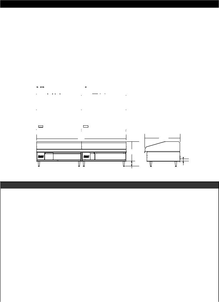
6.8” |
|
|
|
|
36” |
|
|
|
|
|
|
||||||||
|
|
|
|
|
|
|
|
|
|
|
|
|
|
|
|
|
|
||
|
|
|
|
Elec. Connect. |
|
|
|
|
|
|
|
|
|
||||||
Elec. Connect. |
|
|
|
|
|
|
|
|
|
|
|
||||||||
|
|
(160 & 172 only) |
|
|
|
|
|
|
|
|
|
||||||||
|
|
|
|
|
|
|
|
|
|
|
|
|
|||||||
|
|
|
|
|
|
|
|
|
|
|
|
|
|
|
|
|
|
|
|
|
|
|
|
|
|
|
|
|
|
|
|
|
|
|
|
|
|
|
|
|
|
|
|
|
|
|
|
|
|
|
|
|
|
|
|
|
|
|
|
|
|
|
|
|
|
|
|
|
|
|
|
|
|
|
|
|
|
|
|
|
|
|
|
|
|
|
|
|
|
|
|
|
|
|
|
|
|
|
|
|
|
|
|
|
|
|
|
|
|
|
|
|
|
|
|
|
|
|
|
|
|
|
|
|
|
|
|
|
|
|
|
|
|
|
|
|
|
|
|
|
|
|
|
|
|
|
|
|
|
|
|
|
|
|
|
|
|
|
|
W |
D |
H |
|
|
IL1547 |
|
2.5” |
4” (101.6mm) |
Elec. Connect. |
ELECTRICAL SPECIFICATIONS - MARINE
|
|
|
|
|
|
Supply |
|
Amp 3 Ph |
|
Supply |
|
|
Supply |
|
Amp 3 Ph |
|
Supply |
||
|
|
|
|
|
|
|
|
|
|
|
|
|
|
|
|
||||
|
|
|
|
Kw |
Amp |
Wire |
|
|
|
Wire |
Kw |
Amp |
Wire |
|
|
|
|
|
Wire 3 |
Current Model |
Volts AC |
Hz. |
Ph. |
TOT. |
1PH. |
1 PH |
L1 |
L2 |
L3 |
3 PH |
TOT. |
1PH. |
1 PH |
L1 |
|
L2 |
|
L3 |
PH |
|
|
|
|
|
|
|
|
|
|
|
|
|
|
|
|
|
|
|
|
124T-440VM |
440V |
50/60 |
3 |
12 |
|
|
23.6 |
13.6 |
13.6 |
10 |
|
|
|
|
|
|
|
|
|
|
|
|
|
|
|
|
|
|
|
|
|
|
|
|
|
|
|
|
|
124T-480VM |
480V |
60 |
3 |
12 |
|
|
22 |
13 |
13 |
12 |
|
|
|
|
|
|
|
|
|
|
|
|
|
|
|
|
|
|
|
|
|
|
|
|
|
|
|
|
|
124T-M |
208/240V |
60 |
1/3 |
12 |
58 |
4 |
50 |
29 |
29 |
6 |
|
|
|
|
|
|
|
|
|
|
|
|
|
|
|
|
|
|
|
|
|
|
|
|
|
|
|
|
|
136T-440VM |
440V |
60 |
3 |
18 |
|
|
23.6 |
23.6 |
23.6 |
12 |
|
|
|
|
|
|
|
|
|
|
|
|
|
|
|
|
|
|
|
|
|
|
|
|
|
|
|
|
|
136T-480VM |
480V |
60 |
3 |
18 |
|
|
22 |
22 |
22 |
12 |
|
|
|
|
|
|
|
|
|
|
|
|
|
|
|
|
|
|
|
|
|
|
|
|
|
|
|
|
|
136THE-480VM |
480V |
50/60 |
3 |
18 |
|
|
21.7 |
21.7 |
21.7 |
10 |
|
|
|
|
|
|
|
|
|
|
|
|
|
|
|
|
|
|
|
|
|
|
|
|
|
|
|
|
|
124T-380VM |
380V |
50/60 |
3 |
12 |
|
|
27.3 |
15.7 |
15.7 |
10 |
|
|
|
|
|
|
|
|
|
|
|
|
|
|
|
|
|
|
|
|
|
|
|
|
|
|
|
|
|
136T-M |
208/240V |
60 |
1/3 |
18 |
87 |
2 |
50 |
50 |
50 |
6 |
|
|
|
|
|
|
|
|
|
|
|
|
|
|
|
|
|
|
|
|
|
|
|
|
|
|
|
|
|
148T-440VM |
440V |
60 |
3 |
24 |
|
|
35.4 |
35.4 |
21.7 |
8 |
|
|
|
|
|
|
|
|
|
|
|
|
|
|
|
|
|
|
|
|
|
|
|
|
|
|
|
|
|
148T-480VM |
480V |
60 |
3 |
24 |
|
|
33 |
33 |
22 |
8 |
|
|
|
|
|
|
|
|
|
|
|
|
|
|
|
|
|
|
|
|
|
|
|
|
|
|
|
|
|
148T-M |
208/240V |
60 |
1/3 |
24 |
116 |
1 |
75 |
75 |
50 |
3 |
|
|
|
|
|
|
|
|
|
|
|
|
|
|
|
|
|
|
|
|
|
|
|
|
|
|
|
|
|
160T-M |
208/240V |
60 |
1/3 |
12 |
58 |
2 |
50 |
29 |
29 |
6 |
18 |
87 |
2 |
50 |
|
50 |
|
50 |
6 |
|
|
|
|
|
|
|
|
|
|
|
|
|
|
|
|
|
|
|
|
160T-440VM |
440V |
60 |
3 |
12 |
|
|
23.6 |
13.6 |
13.6 |
10 |
18 |
|
|
23.6 |
|
23.6 |
|
23.6 |
10 |
|
|
|
|
|
|
|
|
|
|
|
|
|
|
|
|
|
|
|
|
172T-440VM |
440V |
60 |
3 |
18 |
|
|
23.6 |
23.6 |
23.6 |
12 |
18 |
|
|
23.6 |
|
23.6 |
|
23.6 |
12 |
|
|
|
|
|
|
|
|
|
|
|
|
|
|
|
|
|
|
|
|
172T-480VM |
480V |
60 |
3 |
18 |
|
|
22 |
22 |
22 |
12 |
18 |
|
|
22 |
|
22 |
|
22 |
12 |
|
|
|
|
|
|
|
|
|
|
|
|
|
|
|
|
|
|
|
|
172T-M |
208/240V |
60 |
1/3 |
18 |
87 |
2 |
50 |
50 |
50 |
6 |
18 |
87 |
2 |
50 |
|
50 |
|
50 |
6 |
4

EQUIPMENT SPECIFICATIONS
|
|
|
|
Kw |
Amp |
Supply |
|
Amp 3 Ph |
|
Supply |
Kw |
Amp |
Supply |
Amp 3 Ph |
Supply |
|||
Current Model |
Volts AC |
Hz. |
PH |
Wire |
|
|
|
|
Wire 3 |
Wire |
|
|
|
Wire |
||||
TOT. |
1PH. |
L1 |
L2 |
|
L3 |
TOT. |
1PH. |
L1 |
L2 |
L3 |
||||||||
|
|
|
|
1 PH |
|
PH |
1 PH |
3 PH |
||||||||||
|
|
|
|
|
|
|
|
|
||||||||||
|
|
|
|
|
|
|
|
|
|
|
|
|
|
|
|
|
|
|
124T |
208/240V |
60 |
1/3 |
12 |
58 |
4 |
50 |
29 |
|
29 |
6 |
|
|
|
|
|
|
|
124T-220V |
220V |
50/60 |
1/3 |
10 |
45.5 |
6 |
39.4 |
22.7 |
|
22.7 |
8 |
|
|
|
|
|
|
|
124T-220VCW |
220V |
50/60 |
1/3 |
10 |
45.5 |
6 |
39.4 |
22.7 |
|
22.7 |
8 |
|
|
|
|
|
|
|
124T-380V |
380V |
60 |
3 |
12 |
|
|
27.3 |
15.7 |
|
15.7 |
10 |
|
|
|
|
|
|
|
124T-480V |
480V |
60 |
3 |
12 |
|
|
22 |
13 |
|
13 |
12 |
|
|
|
|
|
|
|
124T-480VSJ |
480V |
60 |
3 |
12 |
|
|
22 |
13 |
|
13 |
12 |
|
|
|
|
|
|
|
124T-BK |
208/240V |
60 |
1/3 |
12 |
58 |
4 |
50 |
29 |
|
29 |
6 |
|
|
|
|
|
|
|
124TC |
208/240V |
60 |
1/3 |
12 |
58 |
4 |
50 |
29 |
|
29 |
6 |
|
|
|
|
|
|
|
124TCHE |
208/240 |
60 |
1/3 |
12 |
58 |
4 |
50 |
29 |
|
29 |
6 |
|
|
|
|
|
|
|
124TC-TE |
208/240V |
60 |
1/3 |
12 |
58 |
4 |
50 |
29 |
|
29 |
6 |
|
|
|
|
|
|
|
124THE |
208/240V |
60 |
1/3 |
12 |
58 |
4 |
50 |
29 |
|
29 |
6 |
|
|
|
|
|
|
|
124THE2L |
208/240V |
60 |
1/3 |
12 |
58 |
4 |
50 |
29 |
|
29 |
6 |
|
|
|
|
|
|
|
124T-PE |
208/240V |
60 |
1/3 |
12 |
58 |
4 |
50 |
29 |
|
29 |
6 |
|
|
|
|
|
|
|
124T-PE-480V |
480V |
60 |
3 |
12 |
|
|
22 |
13 |
|
13 |
12 |
|
|
|
|
|
|
|
124TR |
208/240 |
60 |
1/3 |
12 |
58 |
4 |
50 |
29 |
|
29 |
6 |
|
|
|
|
|
|
|
124TSS |
208/240V |
60 |
1/3 |
12 |
58 |
4 |
50 |
29 |
|
29 |
6 |
|
|
|
|
|
|
|
124TSS-480V |
480V |
60 |
3 |
12 |
|
|
22 |
13 |
|
13 |
12 |
|
|
|
|
|
|
|
136T |
208/240V |
60 |
1/3 |
18 |
87 |
2 |
50 |
50 |
|
50 |
6 |
|
|
|
|
|
|
|
136T-380V |
380V |
60 |
3 |
18 |
|
|
27.3 |
27.3 |
|
27.3 |
10 |
|
|
|
|
|
|
|
136T-480V |
480V |
60 |
3 |
18 |
|
|
22 |
22 |
|
22 |
12 |
|
|
|
|
|
|
|
136TC |
208/240 |
60 |
3 |
18 |
87 |
2 |
50 |
50 |
|
50 |
6 |
|
|
|
|
|
|
|
136TC-TE |
208/240 |
60 |
1/3 |
18 |
87 |
2 |
50 |
50 |
|
50 |
6 |
|
|
|
|
|
|
|
136TC-TE-380 |
380V |
50 |
3 |
18 |
|
|
27 |
27 |
|
27 |
10 |
|
|
|
|
|
|
|
136THE-240V |
208/240V |
60 |
1/3 |
18 |
87/75 |
2 |
50/43 |
50/43 |
|
50/43 |
6 |
|
|
|
|
|
|
|
136TNTS |
208/240V |
60 |
1/3 |
18 |
87 |
2 |
50 |
50 |
|
50 |
6 |
|
|
|
|
|
|
|
136T-PE |
208/240 |
60 |
1/3 |
18 |
87 |
2 |
50 |
50 |
|
50 |
6 |
|
|
|
|
|
|
|
148T |
208/240V |
60 |
1/3 |
24 |
116 |
1 |
75 |
75 |
|
50 |
3 |
|
|
|
|
|
|
|
148T-PE-480V |
480V |
60 |
3 |
24 |
|
|
33 |
33 |
|
22 |
8 |
|
|
|
|
|
|
|
148T-480V |
480V |
60 |
3 |
24 |
|
|
33 |
33 |
|
22 |
8 |
|
|
|
|
|
|
|
148TC |
208/240V |
60 |
1/3 |
24 |
116 |
1 |
75 |
75 |
|
50 |
3 |
|
|
|
|
|
|
|
148TC-TE |
208/240V |
60 |
1/3 |
24 |
116 |
1 |
75 |
75 |
|
50 |
3 |
|
|
|
|
|
|
|
148TC-TE-380 |
380V |
50 |
3 |
24 |
|
|
41 |
41 |
|
27 |
6 |
|
|
|
|
|
|
|
148TC-TE-480 |
480V |
60 |
3 |
24 |
|
|
31 |
33 |
|
22 |
8 |
|
|
|
|
|
|
|
148THE-208V |
208/240 |
60 |
1/3 |
24 |
116 |
1 |
75 |
75 |
|
50 |
3 |
|
|
|
|
|
|
|
148T-PE |
208/240V |
60 |
1/3 |
24 |
116 |
1 |
75 |
75 |
|
50 |
3 |
|
|
|
|
|
|
|
148T-SJ |
208/240V |
60 |
1/3 |
24 |
116 |
1 |
75 |
75 |
|
50 |
3 |
|
|
|
|
|
|
|
148TSS |
208/240V |
60 |
1/3 |
24 |
116 |
1 |
75 |
75 |
|
50 |
3 |
|
|
|
|
|
|
|
148TSS-480V |
480V |
60 |
3 |
24 |
|
|
33 |
33 |
|
22 |
8 |
|
|
|
|
|
|
|
160T |
208/240V |
60 |
1/3 |
12 |
58 |
2 |
50 |
29 |
|
29 |
6 |
18 |
87 |
2 |
50 |
50 |
50 |
6 |
160T-480V |
480V |
60 |
3 |
12 |
|
|
22 |
13 |
|
13 |
12 |
18 |
|
|
22 |
22 |
22 |
12 |
160T-480VCP |
480V |
60 |
3 |
12 |
|
|
22 |
13 |
|
13 |
12 |
18 |
|
|
22 |
22 |
22 |
12 |
160TC-TE |
208/240V |
60 |
1/3 |
12 |
58 |
4 |
50 |
29 |
|
29 |
6 |
18 |
87 |
2 |
50 |
50 |
50 |
6 |
160TC-TE-480 |
480V |
60 |
3 |
24 |
|
|
33 |
33 |
|
22 |
8 |
|
|
|
|
|
|
|
160THE |
208/240 |
60 |
1/3 |
12 |
58 |
4 |
50 |
29 |
|
29 |
6 |
18 |
87 |
2 |
50 |
50 |
50 |
6 |
160TSS |
208/240V |
60 |
1/3 |
12 |
58 |
2 |
50 |
29 |
|
29 |
6 |
18 |
87 |
6 |
50 |
50 |
50 |
6 |
160TSS-480V |
480V |
60 |
3 |
12 |
|
|
22 |
13 |
|
13 |
12 |
|
|
|
22 |
22 |
22 |
12 |
172T |
208/240V |
60 |
1/3 |
18 |
87 |
2 |
50 |
50 |
|
50 |
6 |
18 |
87 |
2 |
50 |
50 |
50 |
6 |
172T-480V |
480V |
60 |
3 |
18 |
|
|
22 |
22 |
|
22 |
12 |
18 |
|
|
22 |
22 |
22 |
12 |
172T-480V-CP |
480V |
60 |
3 |
18 |
|
|
22 |
22 |
|
22 |
12 |
18 |
|
|
22 |
22 |
22 |
12 |
172T-480VSJ |
480V |
60 |
3 |
18 |
|
|
22 |
22 |
|
22 |
12 |
18 |
|
|
22 |
22 |
22 |
12 |
172TC |
208/240V |
60 |
1/3 |
18 |
87 |
2 |
50 |
50 |
|
50 |
6 |
18 |
87 |
2 |
50 |
50 |
50 |
6 |
|
|
|
|
|
|
|
|
|
|
|
|
|
|
|
|
|
|
|
172TC-480V |
480V |
60 |
3 |
18 |
|
|
22 |
22 |
|
22 |
12 |
18 |
|
|
22 |
22 |
22 |
12 |
|
|
|
|
|
|
|
|
|
|
|
|
|
|
|
|
|
|
|
172TC-TE |
208/240V |
60 |
1/3 |
18 |
87 |
2 |
50 |
50 |
|
50 |
6 |
18 |
87 |
2 |
50 |
50 |
50 |
6 |
172T-PE |
208/240V |
60 |
1/3 |
18 |
87 |
2 |
50 |
50 |
|
50 |
6 |
18 |
87 |
2 |
50 |
50 |
50 |
6 |
172T-PE-480V |
480V |
60 |
3 |
18 |
|
|
22 |
22 |
|
22 |
12 |
18 |
|
|
22 |
22 |
22 |
12 |
172T-SJ |
208/240V |
60 |
1/3 |
18 |
87 |
2 |
50 |
50 |
|
50 |
6 |
18 |
87 |
2 |
50 |
50 |
50 |
6 |
172TSS |
208/240V |
60 |
1/3 |
18 |
87 |
2 |
50 |
50 |
|
50 |
6 |
18 |
87 |
2 |
50 |
50 |
50 |
6 |
|
|
|
|
|
|
|
|
|
|
|
|
|
|
|
|
|
|
|
5

EQUIPMENT DESCRIPTION
Griddle Surface
Gutter
Grease Pan
Feet
IL1553
Section
Temp. Dial Section
Pilot Light
Exterior Construction
The griddle dimensions are 17” (43.18cm) High, 30” (76.20cm) Deep, and width is dependent on the actual model number.
The Sides, Bottom, and Rear wall are constructed of double wall stainless steel, which allows closer installation to combustible surfaces.
The griddle surface is made of 1” thick, highly polished steel to reduce hot and cold spots, recovery problems, warping, and ensure even heat to the edges of the griddle.
Controls
Each twelve-inch section has its own temperature dial that snaps into place to lock in any temperature from 175°F to 450°F (79°C to 232°C) in 25° increments.
Each twelve-inch section of the griddle is controlled by an area sensitive RTD probe, which can sense and react to a temperature change of +/- 4°F.
Each twelve-inch section has a set of 6 K.W. elements for high eficiency, quick recovery and outstanding performance
Technical
The 100 series thermostat griddle operates on either 208, 220, 240, 380, 440 or 480V, are shipped three phase, (unless in speciic speciications). 208, 220, 240V can be ield converted to single phase.
Minimum clearances: 2” from side and back
NOTICE |
The data plate is on the right side of the griddle. The griddle voltage, |
|
wattage, serial number, wire size, and clearance speciications are on |
|
the data plate. This information should be carefully read and understood |
|
before proceeding with the installation. |
6

UNPACKING
Receiving the Griddle
Upon receipt, check for freight damage, both visible and concealed. Visible damage should be noted on the freight bill at the time of delivery and signed by the carrier’s agent. Concealed loss or damage means it does not become apparent until the merchandise has been unpacked. If concealed loss or damage is discovered upon unpacking, make a written request for inspection by the carrier’s agent within 15 days of delivery. All packing
material should be kept for inspection. Do not return damaged merchandise to Star Manufacturing Company. File your claim with the carrier.
Location
Prior to un-crating, move the griddle as near to its intended location as practical. The crating will help protect the unit from the physical damage normally associated with moving it through hallways and doorways.
Un-crating
The griddle will arrive completely assembled inside a wood frame and strapped to a skid. Cut the straps and remove the wood frame.
The griddle can now be removed from the skid.
CAUTION
CAUTION
THE UNIT IS EXTREMELY HEAVY. FOR SAFE HANDLING, INSTALLER SHOULD OBTAIN HELP AS NEEDED, OR EMPLOY APPROPRIATE MATERIALS HANDLING EQUIPMENT (SUCH AS A FORKLIFT, DOLLY, OR PALLET JACK) TO REMOVE THE UNIT FROM THE SKID AND MOVE IT TO THE PLACE OF
INSTALLATION.
ANY STAND, COUNTER OR OTHER DEVICE ON WHICH GRIDDLE WILL BE LOCATED MUST BE DESIGNED TO SUPPORT THE WEIGHT OF THE GRIDDLE.
SHIPPING STRAPS ARE UNDER TENSION AND CAN SNAP BACK WHEN CUT.
WARNING
7

INSTALLATION
ABOVE: typical leg installation.
Leg Installation
There are four, 4” legs provided for 2, 3 and 4 foot griddles.
There are eight 4” legs provided for 5 and 6  foot griddles.
The legs are shipped in the grease drawers of the griddle. Install them into the threaded holes on the underside of the griddle body.
Leveling adjustment may be done by
screwing the bottom portion of the leg in and out.
IL1554
Std Leg
Marine Bolt Down Leg
2.5”
IL1550
For bolt down legs see above illustration for dimensions.
WARNING
WARNING
NOTICE:
THIS APPLIANCE MUST BE GROUNDED AT THE TERMINAL
PROVIDED. FAILURE TO GROUND THE APPLIANCE COULD RESULT IN ELECTROCUTION AND DEATH.
INSTALLATION OF THE UNIT MUST BE DONE BY PERSONNEL QUALIFIED TO WORK WITH ELECTRICITY AND PLUMBING. IMPROPER INSTALLATION CAN CAUSE INJURY TO PERSONNEL AND/OR DAMAGE TO EQUIPMENT. UNIT MUST BE INSTALLED IN ACCORDANCE WITH ALL APPLICABLE CODES.
The data plate is located on the right side of the griddle. The grill voltage, wattage, serial number, wire size, and clearance speciications are on
the data plate. This information should be carefully read and understood before proceeding with the installation.
NOTICE: The installation of any components such as a vent hood, grease extractors, ire extinguisher systems, must conform to their applicable National, State and locally recognized installation standards.
ALWAYS KEEP THE AREA NEAR THE APPLIANCE FREE FROM
COMBUSTIBLE MATERIALS.
CAUTION
KEEP FLOOR IN FRONT OF EQUIPMENT CLEAN AND DRY. IF SPILLS OCCUR, CLEAN IMMEDIATELY, TO AVOID THE DANGER OF SLIPS OR
FALLS.
WARNING
8
 Loading...