


RCM4015
Table of contents
 Loading...
Table of Contents
Cover photo may show optional equipment
not supplied with standard unit.
Read the Operator’s Manual entirely. When you
see this symbol, the subsequent instructions and
warnings are serious - follow without exception.
Your life and the lives of others depend on it!
!
© Copyright 2015 Printed
37900
RC4015 and RCM4015 Series 2 S/N 944961+
Rotary Cutters
330-845M
Operator’s Manual
10/21/ 15

Table of Contents
RC4015 and RCM4015 Series 2 S/N 944961+ Rotary Cutters 330-845M
10/21/15
© Copyright 2015 All rights Reserved
Land Pride provides this publication “as is” without warranty of any kind, either expressed or implied. While every precaution has been taken in the
preparation of this manual, Land Pride assumes no responsibility for errors or omissions. Neither is any liability assumed for damages resulting from the use
of the information contained herein. Land Pride reserves the right to revise and improve its products as it sees fit. This publication describes the state of this
product at the time of its publication, and may not reflect the product in the future.
Land Pride is a registered trademark.
All other brands and product names are trademarks or registered trademarks of their respective holders.
Printed in the United States of America.
Table of Contents
Important Safety Information . . . . . . . . . . . . . 1
Safety at All Times . . . . . . . . . . . . . . . . . . . . . . . . . 1
Safety Labels . . . . . . . . . . . . . . . . . . . . . . . . . . . . . 4
Introduction . . . . . . . . . . . . . . . . . . . . . . . . . . 10
Application . . . . . . . . . . . . . . . . . . . . . . . . . . . . . . 10
Using This Manual . . . . . . . . . . . . . . . . . . . . . . . . . 10
Owner Assistance . . . . . . . . . . . . . . . . . . . . . . . . . 10
Serial Number . . . . . . . . . . . . . . . . . . . . . . . . . . 10
Section 1: Assembly & Set-up . . . . . . . . . . . 11
Tractor Requirements . . . . . . . . . . . . . . . . . . . . . . 11
Horsepower . . . . . . . . . . . . . . . . . . . . . . . . . . . . 11
Drawbar Set-up . . . . . . . . . . . . . . . . . . . . . . . . . 11
PTO Speed . . . . . . . . . . . . . . . . . . . . . . . . . . . . 11
Hydraulic Outlets . . . . . . . . . . . . . . . . . . . . . . . . 11
Before You Start . . . . . . . . . . . . . . . . . . . . . . . . . . 11
Torque Requirements . . . . . . . . . . . . . . . . . . . . . . 11
Hitch Types . . . . . . . . . . . . . . . . . . . . . . . . . . . . . . 12
Standard Clevis Hitch . . . . . . . . . . . . . . . . . . . . . 12
Land Pride Performance Hitch (Optional) . . . . . . 12
Bar-Tite Hitch (Optional) . . . . . . . . . . . . . . . . . . 12
Ball Hitch (Optional) . . . . . . . . . . . . . . . . . . . . . . 12
Pintle Hitch (Optional) . . . . . . . . . . . . . . . . . . . . 12
Hitch Assembly . . . . . . . . . . . . . . . . . . . . . . . . . . . 13
Park Jack Assembly . . . . . . . . . . . . . . . . . . . . . . . 13
Spring Hose Loop Assembly . . . . . . . . . . . . . . . . . 13
Tractor Shutdown Procedure . . . . . . . . . . . . . . . . . 13
Standard Clevis Hitch Hook-up . . . . . . . . . . . . . . . 14
LP Performance Hitch Hook-up . . . . . . . . . . . . . . . 15
Bar-Tite Hitch Hook-up . . . . . . . . . . . . . . . . . . . . . 16
Hydraulic Hook-up . . . . . . . . . . . . . . . . . . . . . . . . . 17
Right & Left Wing Set-up . . . . . . . . . . . . . . . . . . . . 17
Lower Wings . . . . . . . . . . . . . . . . . . . . . . . . . . . . . 18
Driveline Installation . . . . . . . . . . . . . . . . . . . . . . . 18
Driveline Hook-up to Tractor PTO . . . . . . . . . . . . . 20
Adjust Driveline Hanger . . . . . . . . . . . . . . . . . . . . . 20
Driveline Clearance Check . . . . . . . . . . . . . . . . . . 21
Purge Hydraulic System . . . . . . . . . . . . . . . . . . . . 21
Remove Shipping Lugs . . . . . . . . . . . . . . . . . . . . . 22
Unhook Rotary Cutter . . . . . . . . . . . . . . . . . . . . . . 22
Section 2: Adjustments . . . . . . . . . . . . . . . . . 24
Park Jack Angle Alignment . . . . . . . . . . . . . . . . . . 24
Leveling Center Deck & Wings . . . . . . . . . . . . . . . 24
Center Deck Leveling . . . . . . . . . . . . . . . . . . . . . 24
Wing Deck Leveling . . . . . . . . . . . . . . . . . . . . . . 25
Cutting Height Adjustment . . . . . . . . . . . . . . . . . . . 26
LP Performance Hitch Hole Size . . . . . . . . . . . . . . 26
Section 3: Operating Instructions . . . . . . . . . 27
Startup Checklist . . . . . . . . . . . . . . . . . . . . . . . . . . 27
Safety Information . . . . . . . . . . . . . . . . . . . . . . . . . 27
Avoid Extreme Turning Angles . . . . . . . . . . . . . . 28
Tractor & Cutter Inspection . . . . . . . . . . . . . . . . . . 29
Blade Operation Inspection . . . . . . . . . . . . . . . . . . 29
Transport Locks . . . . . . . . . . . . . . . . . . . . . . . . . . . 30
Transporting . . . . . . . . . . . . . . . . . . . . . . . . . . . . . 30
Field Set-up . . . . . . . . . . . . . . . . . . . . . . . . . . . . . . 31
Inspect Field and Cutter Blades . . . . . . . . . . . . . 31
Lower Wing Down & Set Cutting Height . . . . . . . 31
Set Wing Lift Lever In Float Position . . . . . . . . . . 31
Select Gear Range . . . . . . . . . . . . . . . . . . . . . . . 31
Engage Blades . . . . . . . . . . . . . . . . . . . . . . . . . . 31
Disengage Blades . . . . . . . . . . . . . . . . . . . . . . . 32
General Operating Instructions . . . . . . . . . . . . . . . 32
Section 4: Options & Accessories . . . . . . . . 33
Safety Guard . . . . . . . . . . . . . . . . . . . . . . . . . . . . . 33
Tire & Axle Options . . . . . . . . . . . . . . . . . . . . . . . . 33
Hitch Options . . . . . . . . . . . . . . . . . . . . . . . . . . . . . 33
Mechanical Wing Lift . . . . . . . . . . . . . . . . . . . . . . . 34
Installation Instructions . . . . . . . . . . . . . . . . . . . . 34
Operating Instructions . . . . . . . . . . . . . . . . . . . . 34
Hydraulic Accessories . . . . . . . . . . . . . . . . . . . . . . 35
Hydraulic Wing Control Kit . . . . . . . . . . . . . . . . . 35
Selector Control Valve Kit . . . . . . . . . . . . . . . . . . 35
Light Kit Option (LED) . . . . . . . . . . . . . . . . . . . . . . 36
Section 5: Maintenance & Lubrication . . . . . 38
General Maintenance Information . . . . . . . . . . . . . 38
Tractor Maintenance . . . . . . . . . . . . . . . . . . . . . . . 38
Cutter Blade Maintenance . . . . . . . . . . . . . . . . . . . 38
Drivelines With Slip Clutches . . . . . . . . . . . . . . . . . 40
Type A Clutches . . . . . . . . . . . . . . . . . . . . . . . . . 40
Type B Clutches . . . . . . . . . . . . . . . . . . . . . . . . . 42
Skid Shoe Maintenance . . . . . . . . . . . . . . . . . . . . . 43
Center Skid Shoes . . . . . . . . . . . . . . . . . . . . . . . 43
Wing Skid Shoes . . . . . . . . . . . . . . . . . . . . . . . . 43
Spindle Gearbox Shaft Guard . . . . . . . . . . . . . . . . 43
Tire Maintenance . . . . . . . . . . . . . . . . . . . . . . . . . . 44
Long-term Storage . . . . . . . . . . . . . . . . . . . . . . . . . 44
Ordering Replacement Parts . . . . . . . . . . . . . . . . . 45
Lubrication Points . . . . . . . . . . . . . . . . . . . . . . . . . 46
Section 6: Specifications & Capacities . . . . . 52
Section 7: Features & Benefits . . . . . . . . . . . 54
Section 8: Troubleshooting . . . . . . . . . . . . . . 55
Section 9: Torque & Tire Inflation Chart . . . . 56
Section 10: Warranty . . . . . . . . . . . . . . . . . . . 57
1
Important Safety Information
10/21/15
RC4015 and RCM4015 Series 2 S/N 944961+ Rotary Cutters 330-845M
Table of Contents
Important Safety Information
These are common practices that may or may not be applicable to the products described in
this manual.
▲
Safety at All Times
Thoroughly read and understand
the instructions given in this
manual before operation. Refer to
the “Safety Label” section, read all
instructions noted on them.
Do not allow anyone to operate
this equipment who has not fully
read and comprehended this
manual and who has not been
properly trained in the safe
operation of the equipment.
▲ The operator must not use drugs
or alcohol as they can change the
alertness or coordination of that
person while operating equipment.
The operator should, if taking over-
the-counter drugs, seek medical
advice on whether he/she can
safely operate the equipment.
▲ Operator should be familiar with all
functions of the unit.
▲ Operate controls from the driver’s
seat only. Never operate controls
from the ground.
▲ Make sure all guards and shields
are in place and secured before
operating implement.
▲ Keep all bystanders away from
equipment and work area.
▲ Do not leave tractor or implement
unattended with engine running.
▲ Dismounting from a moving tractor
can cause serious injury or death.
▲ Do not allow anyone to stand
between tractor and implement
while backing up to implement.
▲ Keep hands, feet, and clothing
away from power-driven parts.
▲ Watch out for fences, trees, rocks,
wires, etc., while operating and
transporting implement.
▲ Turning tractor too tight may cause
hitched machinery to ride up on
wheels. This could result in injury
or equipment damage.
Look For The Safety Alert Symbol
The SAFETY ALERT SYMBOL indicates there is a
potential hazard to personal safety involved and extra
safety precaution must be taken. When you see this
symbol, be alert and carefully read the message that
follows it. In addition to design and configuration of
equipment, hazard control, and accident prevention are
dependent upon the awareness, concern, prudence, and
proper training of personnel involved in the operation,
transport, maintenance, and storage of equipment.
Parts Manual QR Locator
The QR (Quick Reference) code on the
cover and to the left will take you to the
Parts Manual for this equipment.
Download the appropriate App on your
smart phone, open the App, point your
phone on the QR code and take a picture.
Dealer QR Locator
The QR code on the left will
link you to available dealers
for Land Pride products.
Refer to Parts Manual QR
Locator on this page for
detailed instructions.
!
Be Aware of
Signal Words
A Signal word designates a degree or
level of hazard seriousness. The
signal words are:
Indicates an imminently hazardous
situation which, if not avoided, will
result in death or serious injury. This
signal word is limited to the most
extreme situations, typically for
machine components that, for
functional purposes, cannot be
guarded.
!
DANGER
Indicates a potentially hazardous
situation which, if not avoided, could
result in death or serious injury, and
includes hazards that are exposed
when guards are removed. It may also
be used to alert against unsafe
practices.
Indicates a potentially hazardous
situation which, if not avoided, may
result in minor or moderate injury. It
may also be used to alert against
unsafe practices.
!
WARNING
!
CAUTION
For Your Protection
▲ Thoroughly read and understand
the “Safety Label” section, read
all instructions noted on them.
Tractor Shutdown & Storage
▲ If engaged, disengage PTO.
▲ Lower attached implement to
ground, put tractor in park or set
park brake, turn off engine, and
remove switch key to prevent
unauthorized starting.
▲ Wait for all components to come to
a complete stop before leaving the
operator’s seat.
▲ Detach and store implement in an
area where children normally do
not play. Secure implement using
blocks and supports.
OFF
R
E
M
O
V
E
2
Important Safety Information
RC4015 and RCM4015 Series 2 S/N 944961+ Rotary Cutters 330-845M
10/21/15
Table of Contents
These are common practices that may or may not be applicable to the products described in
this manual.
Use Safety
Lights and Devices
▲ Slow moving tractors,
self-propelled equipment, and
towed implements can create a
hazard when driven on public
roads. They are difficult to see,
especially at night.
▲ Flashing warning lights and turn
signals are recommended
whenever driving on public roads.
Use A Safety Chain
▲ A safety chain will help control
drawn machinery should it
separate from the tractor drawbar.
▲ Use a chain with the strength
rating equal to or greater than the
gross weight of the towed
machinery.
▲ Attach the chain to the tractor
drawbar support or other specified
anchor location. Allow only
enough slack in the chain to
permit turning.
▲ Do not use safety chain for towing.
▲ Maximum transport speed for an
attached implement is 20 mph. DO
NOT EXCEED. Never travel at a
speed which does not allow
adequate control of steering and
stopping. Some rough terrains
require a slower speed.
▲ As a guideline, use the following
maximum speed weight ratios for
an attached implement:
20 mph when weight of attached
implement is less than or equal to
the weight of machine towing the
implement.
10 mph when weight of attached
implement exceeds weight of
machine towing implement but
not more than double the weight.
▲ IMPORTANT: Do not tow a load
that is more than double the weight
of the machine towing the load.
Transport
Machinery Safely
▲ Comply with state and local laws.
▲ Use towing vehicle and trailer of
adequate size and capacity.
▲ Secure equipment towed on a
trailer with tie downs and chains.
▲ Sudden braking can cause a trailer
to swerve and upset. Reduce
speed if trailer is not equipped with
brakes.
▲ Avoid contact with any over head
utility lines or electrically charged
conductors.
▲ Engage park brake when stopped
on an incline.
Practice Safe Maintenance
▲ Understand procedure before doing
work. Use proper tools and
equipment, refer to Operator’s
Manual for additional information.
▲ Work in a clean dry area.
▲ Lower attached implement to the
ground, put tractor in park, turn off
engine, and remove key before
performing maintenance.
▲ Allow implement to cool before
working on it.
▲ Disconnect battery ground cable (-)
before servicing or adjusting
electrical systems or before welding
on implement.
▲ Do not grease or oil implement
while it is in operation.
▲ Inspect all parts. Make certain
parts are in good condition &
installed properly.
▲ Remove buildup of grease, oil, or
debris.
▲ Remove all tools and unused parts
from implement before operation.

3
Important Safety Information
10/21/15
RC4015 and RCM4015 Series 2 S/N 944961+ Rotary Cutters 330-845M
Table of Contents
These are common practices that may or may not be applicable to the products described in
this manual.
Prepare for Emergencies
▲ Be prepared if a fire starts.
▲ Keep a first aid kit and fire
extinguisher handy.
▲ Keep emergency numbers for
doctor, ambulance, hospital, and
fire department near phone.
Avoid High
Pressure Fluids Hazard
▲ Escaping fluid under pressure can
penetrate the skin causing serious
injury.
▲ Avoid the hazard by relieving
pressure before disconnecting
hydraulic lines or performing work
on the system.
▲ Make sure all hydraulic fluid
connections are tight and all
hydraulic hoses and lines are in
good condition before applying
pressure to the system.
▲ Use a piece of paper or
cardboard, NOT BODY PARTS, to
check for suspected leaks.
▲ Wear protective gloves and safety
glasses or goggles when working
with hydraulic systems.
▲ DO NOT DELAY. If an accident
occurs, see a doctor familiar with
this type of injury immediately. Any
fluid injected into the skin or eyes
must be treated within
a few hours or
gangrene may
result.
Tire Safety
▲ Tire changing can be dangerous
and should be preformed by
trained personnel using the
correct tools and equipment.
▲ When inflating tires, use a clip-on
chuck and extension hose long
enough to allow you to stand to
one side and NOT in front of or
over the tire assembly. Use a
safety cage if available.
▲ When removing and installing
wheels, use wheel handling
equipment adequate for the
weight involved.
Use Seat Belt and ROPS
▲ Operate only tractors equipped
with Roll-Over Protective
Structure (ROPS) and seat belt.
▲ Fasten seat belt snugly and
securely to help protect against
serious injury or death from falling
and tractor overturn.
▲ Wearing protective equipment
such as safety shoes, safety
glasses, hard hat, and ear plugs is
highly recommended.
911
Wear
Protective Equipment
▲ Wear protective clothing and
equipment appropriate for the job.
Clothing should be snug fitting
without fringes and pull strings to
avoid entanglement with moving
parts.
▲ Prolonged exposure to loud noise
can cause hearing impairment or
hearing loss. Wear suitable
hearing protection such as
earmuffs or earplugs.
▲ Operating equipment safely
requires the operator’s full
attention. Avoid wearing radio
headphones while operating
machinery.
Keep Riders Off
Machinery
▲ Never carry riders or use
machinery as a person lift.
▲ Riders obstruct operator’s view.
▲ Riders could be struck by foreign
objects or thrown from the
machine.
▲ Never allow children to operate
equipment.
4
Important Safety Information
RC4015 and RCM4015 Series 2 S/N 944961+ Rotary Cutters 330-845M
10/21/15
Table of Contents
Safety Labels
Your Rotary Cutter comes equipped with all safety labels in
place. They were designed to help you safely operate your
implement. Read and follow their directions.
1. Keep all safety labels clean and legible.
2. Refer to this section for proper label placement. Replace
all damaged or missing labels. Order new labels from your
nearest Land Pride dealer. To find your nearest dealer,
visit our dealer locator at www.landpride.com.
3. Some new equipment installed during repair requires
safety labels to be affixed to the replaced component as
specified by Land Pride. When ordering new components
make sure the correct safety labels are included in the
request.
4. Refer to this section for proper label placement.
To install new labels:
a. Clean surface area where label is to be placed.
b. Spray soapy water onto the cleaned area.
c. Peel backing from label and press label firmly onto the
surface.
d. Squeeze out air bubbles with edge of a credit card or
with a similar type of straight edge.
27583
37901
37901
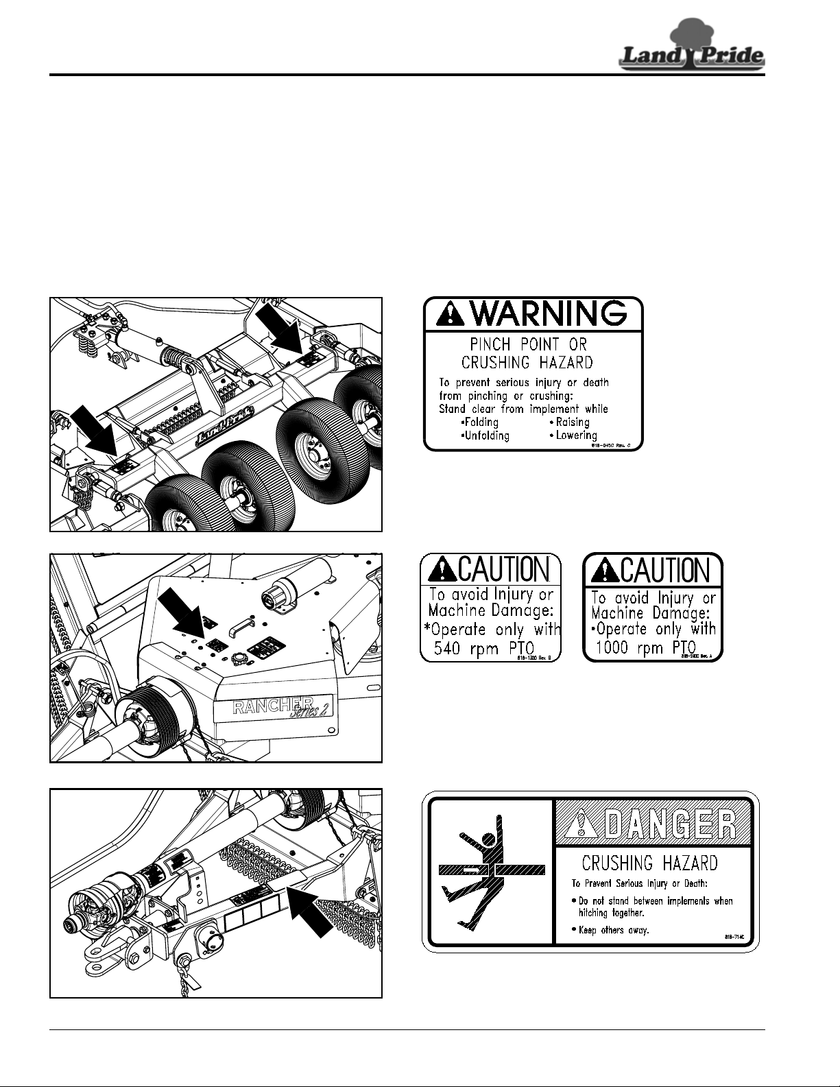
818-714C
Danger! Crushing Hazard
818-130C
Caution! Use 540 rpm PTO only (RC Series Cutters)
818-240C
Caution! Use 1000 rpm PTO only (RCM Series Cutters)
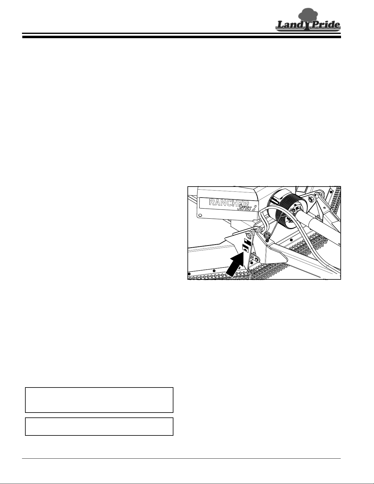
818-045C
Warning! Pinch Point Warning (1-Place)
Located on the back center axle
5
Important Safety Information
10/21/15
RC4015 and RCM4015 Series 2 S/N 944961+ Rotary Cutters 330-845M
Table of Contents
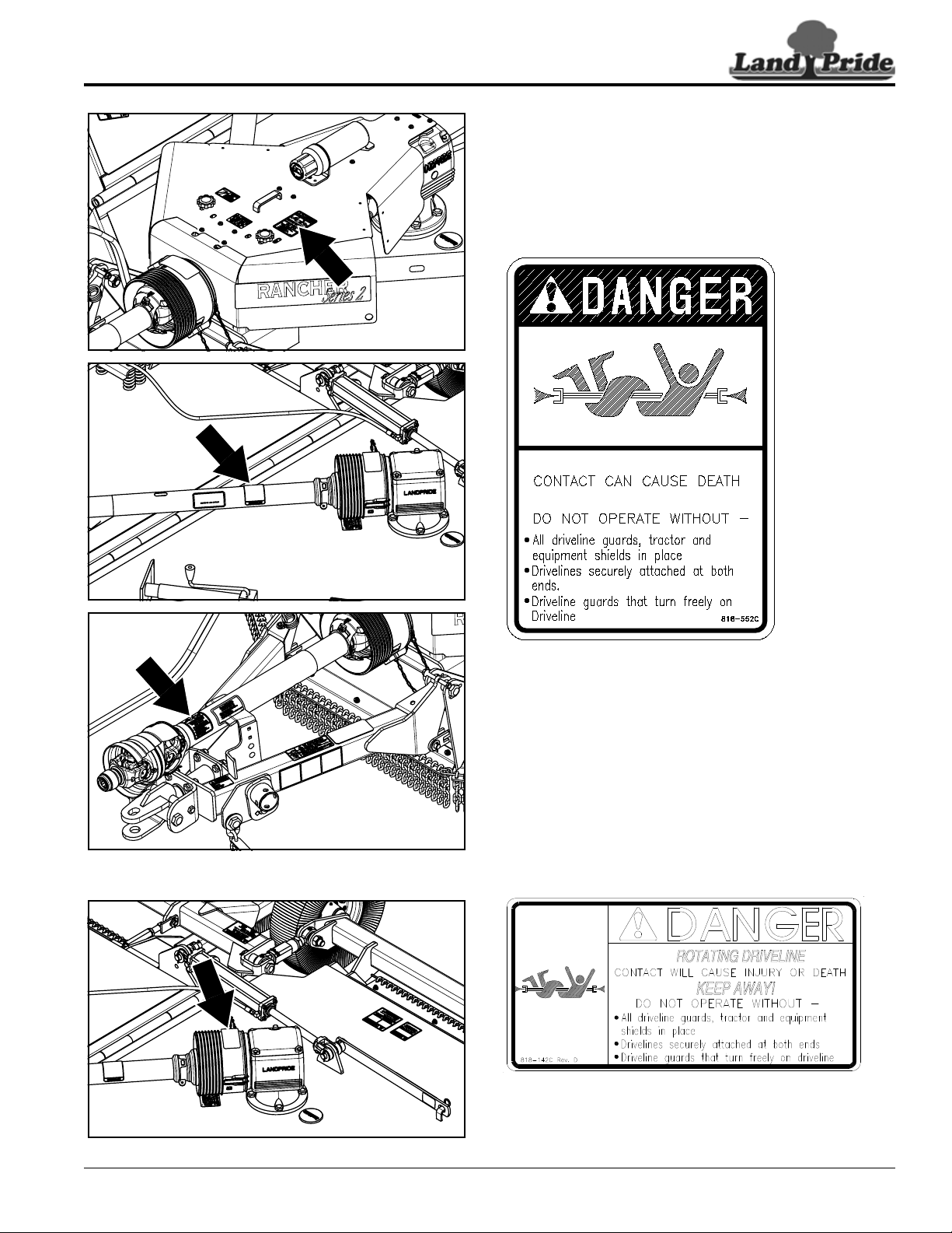
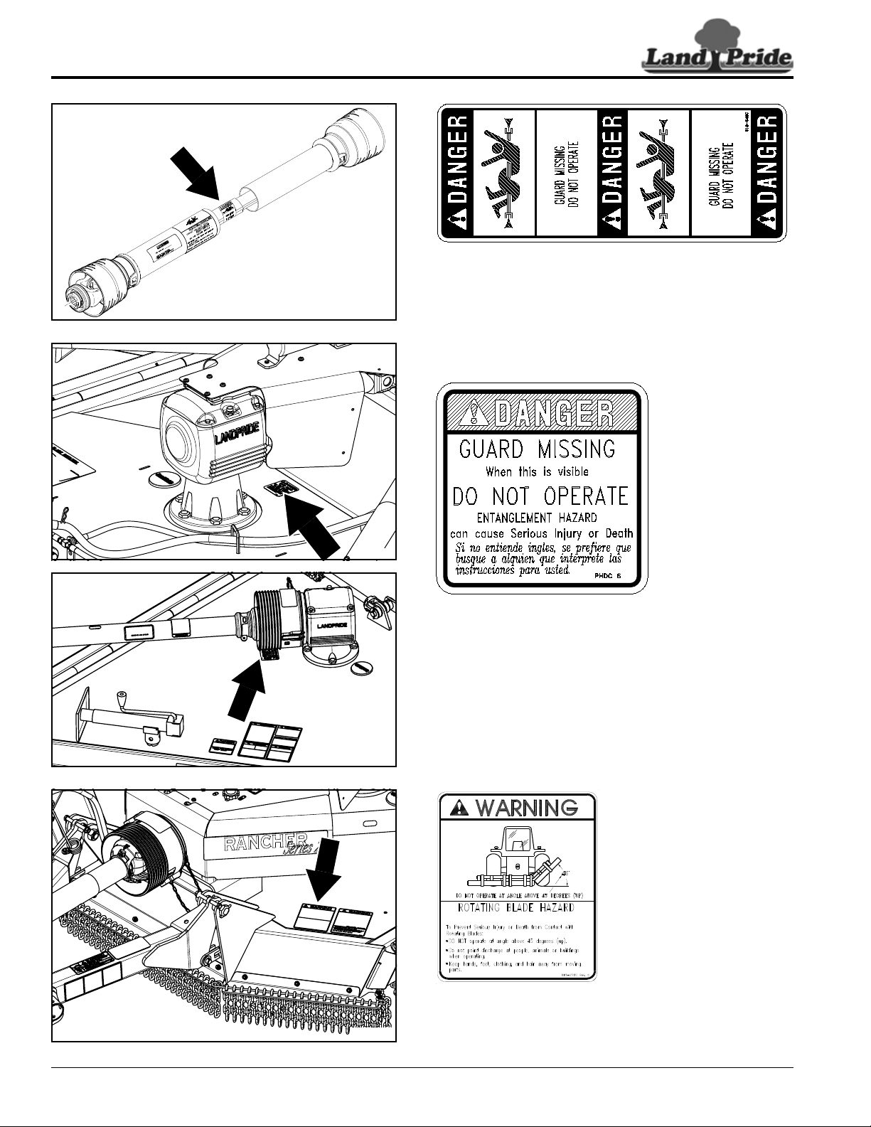
ROTATING DRIVELINE
KEEP AWAY!
37901
37586
37901
37586
818-552C
Danger! Rotating Driveline - Keep Away
1-Place (Top of splitter shield)
3-Places (Main driveline and 2-wing drivelines)
818-142C
Danger! Rotating Driveline - Keep Away (3-Places)
Located on right wing, left wing, and center deck
gearbox shields
6
Important Safety Information
RC4015 and RCM4015 Series 2 S/N 944961+ Rotary Cutters 330-845M
10/21/15
Table of Contents
22296
37609
37586
37901
818-540C
Danger! Shield Missing - DO NOT Operate (3-Places)
Located on main and two wing drivelines
818-543C
Danger! Guard Missing - DO NOT Operate (3-Places)
Located on center deck and both wing decks
818-276C
Warning! Rotating Blade Hazard (1-Place)
Located on left side of center deck

7
Important Safety Information
10/21/15
RC4015 and RCM4015 Series 2 S/N 944961+ Rotary Cutters 330-845M
Table of Contents
37901
37586
37586
818-840C
Danger! Rollover Hazard (1-Place)
Located on left side of center deck
818-561C
Danger! Raised Wing Hazard (2-Places)
Located on the right and left wing decks
818-830C
Safety Combo (2-Places)
Located on the right and left wing decks
8
Important Safety Information
RC4015 and RCM4015 Series 2 S/N 944961+ Rotary Cutters 330-845M
10/21/15
Table of Contents
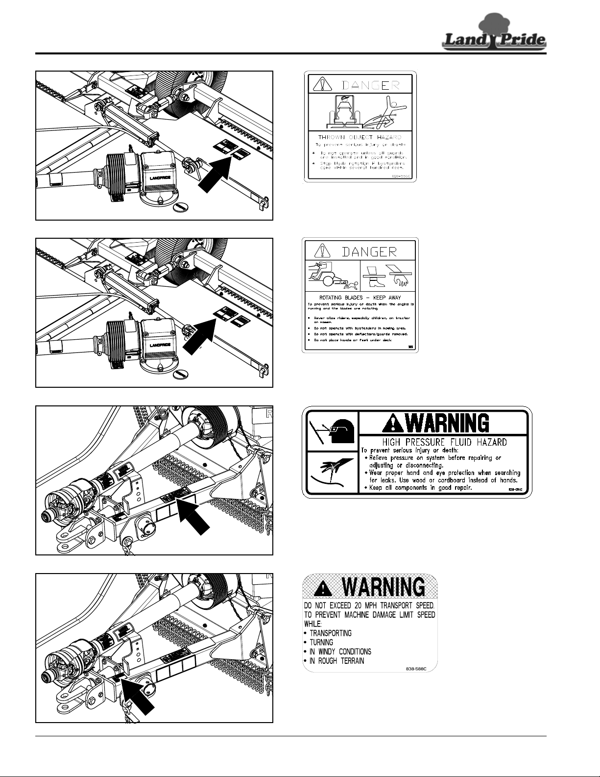
838-588C
Warning! Folding Cutter Speed Warning
818-564C
Danger! Rotating Blade (2-Places)
Located on the right and left wing decks
838-094C
Warning! High Pressure
37588
37588
37901
37901
818-556C
Danger! Thrown Object Hazard (2-Places)
Located on the right and left wing decks

9
Important Safety Information
10/21/15
RC4015 and RCM4015 Series 2 S/N 944961+ Rotary Cutters 330-845M
Table of Contents
37588
37572
37572
37588
818-229C
1 3/4" x 2 3/4" Amber Reflector
Located on front side of left & right wing lock bars
838-614C
2" x 9" Red Reflector
Located on back side of left & right wing lock bars
838-614C
2" x 9" Red Reflector
Located on back side of left & right wing rear axles
838-615C
2" x 9" Amber Reflector
Located on front side of left wing only.
10
Introduction
RC4015 and RCM4015 Series 2 S/N 944961+ Rotary Cutters 330-845M
10/21/15
Table of Contents
Introduction
Owner Assistance
The Online Warranty Registration should be completed
by the dealer at the time of purchase. This information is
necessary to provide you with quality customer service.
The parts on your Rotary Cutter have been specially
designed by Land Pride and should only be replaced with
genuine Land Pride parts. Contact a Land Pride dealer if
customer service or repair parts are required. Your Land
Pride dealer has trained personnel, repair parts, and
equipment needed to service the implement.
Serial Number
Model No. _____________Serial No. ______________
For quick reference and prompt service, record model
number and serial number in the spaces provided above
and again on warranty page 57. Always provide model
number and serial number when ordering parts and in all
correspondences with your Land Pride dealer. Refer to
Figure 1 for location of your serial number plate.
Serial Number Plate Location
Figure 1
Further Assistance
Your dealer wants you to be satisfied with your new
Rotary Cutter. If for any reason you do not understand
any part of this manual or are not satisfied with the
service received, the following actions are suggested:
1. Discuss the matter with your dealership service
manager making sure that person is aware of any
problems you may have and has had the opportunity
to assist you.
2. If you are still not satisfied, seek out the owner or
general manager of the dealership, explain the
problem, and request assistance.
3. For further assistance write to:
Land Pride Service Department
1525 East North Street
P.O. Box 5060
Salina, Ks. 67402-5060
E-mail address
lpservicedept@landpride.com
37902
Land Pride welcomes you to the growing family of new
product owners.
This Rotary Cutter has been designed with care and built
by skilled workers using quality materials. Proper
assembly, maintenance, and safe operating practices will
help you get years of satisfactory use from this machine.
Application
The RC4015 and RCM4015 Series 2 Rotary Cutters are
designed and built by Land Pride to provide excellent
cutting performance on gently sloping or slightly
contoured right-of-ways, pastures, set-aside acres, or row
crop fields. The 15' cutting width and ability to cut weeds
and brush up to 3 1/2" in diameter make them an ideal
cutter for a variety of applications.
All listed models offer a pull-type, narrow A-frame hitch,
and Cat. 5 conventional or Cat. 6 constant velocity main
driveline for attachment to 50-200 HP tractor. The
RC4015 attaches to 540 RPM tractors and RCM4015
attaches to 1000 RPM tractors with 1 3/8" PTO shafts.
They are also offered with various optional hitch types,
axle configurations, tires, safety guards, and deck rings
making them an excellent choice for agricultural, state,
and municipal mowing applications.
See “Specifications & Capacities” on page 52 and
“Features & Benefits” on page 54 for additional
information and performance enhancing options.
Using This Manual
•
This Operator’s Manual is designed to help familiarize
you with safety, assembly, operation, adjustments,
troubleshooting, and maintenance. Read this manual
and follow the recommendations to help ensure safe
and efficient operation.
• The information contained within this manual was
current at the time of printing. Some parts may change
slightly to assure you of the best performance.
• To order a new Operator’s or Parts Manual, contact
your authorized dealer. Manuals can also be
downloaded, free-of-charge, from our website at
www.landpride.com
Terminology
“Right” or “Left” as used in this manual is determined by
facing forward in the direction the machine will operate
while in use unless otherwise stated.
Definitions
IMPORTANT: A special point of information related
to the following topic. Land Pride’s intention is this
information must be read & noted before continuing.
NOTE: A special point of information that the
operator should be aware of before continuing.
11
Section 1: Assembly & Set-up
10/21/15
RC4015 and RCM4015 Series 2 S/N 944961+ Rotary Cutters 330-845M
Table of Contents
Section 1: Assembly & Set-up
Tractor Requirements
Horsepower
!
WARNING
Do not use too small a tractor. Tractors that are too small can
be pushed around and/or flipped over by the weight of the
cutter. Tractors that are too large can damage the cutter.
Tractor horsepower should be within the range noted
below. Tractors outside the range must not be used.
Horsepower Rating . . . . . . . . . . . . . . . . . . 50-200 HP
Drawbar Set-up
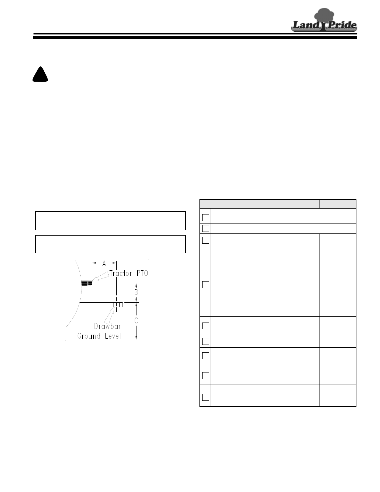
Refer to Figure 1-1:
Maintain proper distance, dimension A, between center
of drawbar hitch pin hole and end of tractor PTO shaft.
Hitch Type . . . . . . . . . . . . . . . . . . . . . . . . . . Draw Bar
540 RPM & 1 3/8", 1000 RPM Rear PTO Speed:
A . . . . . . . . . . . . . . . . . . . . . . . . . . . . . . . . .14"- 16"
B . . . . . . . . . . . . . . . . . . . . . . . . . . . . . . . . . 8" - 10"
C . . . . . . . . . . . . . . . . . . . . . . . . . . . . . . . . 18" - 22"
PTO to Drawbar Distance
Figure 1-1
PTO Speed
Rear PTO Speed:
Model RC4015 . . . . . . . . . . . . . . . . . . . . . 540 RPM
Model RCM4015 . . . . . . . . . . . . . . . . . . .1000 RPM
Hydraulic Outlets
The number of tractor hydraulic duplex outlets is
dependent upon how the Rotary Cutter is set-up.
• Two duplex outlets are required if the wings are folded
up and down simultaneously. (Factory standard)
• Three duplex outlets are required if the wings are
folded up and down independently.
• Float position is highly recommended for the wings.
IMPORTANT: PTO damage may occur if distances
“A” and “B” are not properly maintained.
IMPORTANT: A PTO adaptor should not be used.
Using a PTO adaptor can damage the PTO.
22273
If the tractor does not have the necessary number of
duplex outlets, there are control valve kits available to
add outlets. See “Hydraulic Accessories” on page 35
for a complete description of this kit.
Before You Start
Read and understand the Operator’s Manual for your
cutter. An understanding of how it works will aid in the
assembly and setup of your cutter.
It is best to go through the Pre-Assembly Checklist
before assembling the cutter. Speed up your assembly
task and make the job safer by having all needed parts
and equipment readily at hand.
Torque Requirements
See “Torque Values Chart for Common Bolt Sizes” on
page 56 to determine correct torque values when
tightening hardware. See “Additional Torque Values” at
bottom of chart for exceptions to common torque values.
Assembly Checklist
Check Reference
Have a fork lift or loader with properly sized chains and safety
stands capable of lifting and supporting the equipment on hand.
Have a minimum of two people available during assembly.
Make sure all major components and loose
parts are shipped with the machine.
Operator’s
Manual
Double check to make sure all parts, fasteners,
and pins are installed in the correct location.
Refer to the Parts Manual if unsure. By double
checking, you will lessen the chance of using a
bolt incorrectly that may be needed later.
NOTE: All assembled hardware from the
factory has been installed in the correct
location. Remember location of a part or
fastener if removed during assembly. Keep
parts separated.
Operator’s
Manual
330-845M
Parts Manual
331-970P
Make sure working parts move freely, bolts are
tight & cotter pins are spread.
Page 56
Make sure all grease fittings are in place and
lubricated.
Page 46
Make sure all safety labels are correctly
located and legible. Replace if damaged.
Page 4
Make sure all red and amber reflectors are
correctly located and visible when machine is
in transport position.
Page 9
Make sure all pneumatic tires are properly
inflated and all wheel bolts and axle nuts are
tightened to the specified torque.
Page 56
12
Section 1: Assembly & Set-up
RC4015 and RCM4015 Series 2 S/N 944961+ Rotary Cutters 330-845M
10/21/15
Table of Contents
Hitch Types
The cutter is factory supplied with the standard clevis
hitch. Other optional hitches are available. They include
Land Pride Performance hitch, bar-tite hitch, ball hitch,
and pintle hitch. See your nearest Land Pride dealer
should you want to change your hitch set-up.
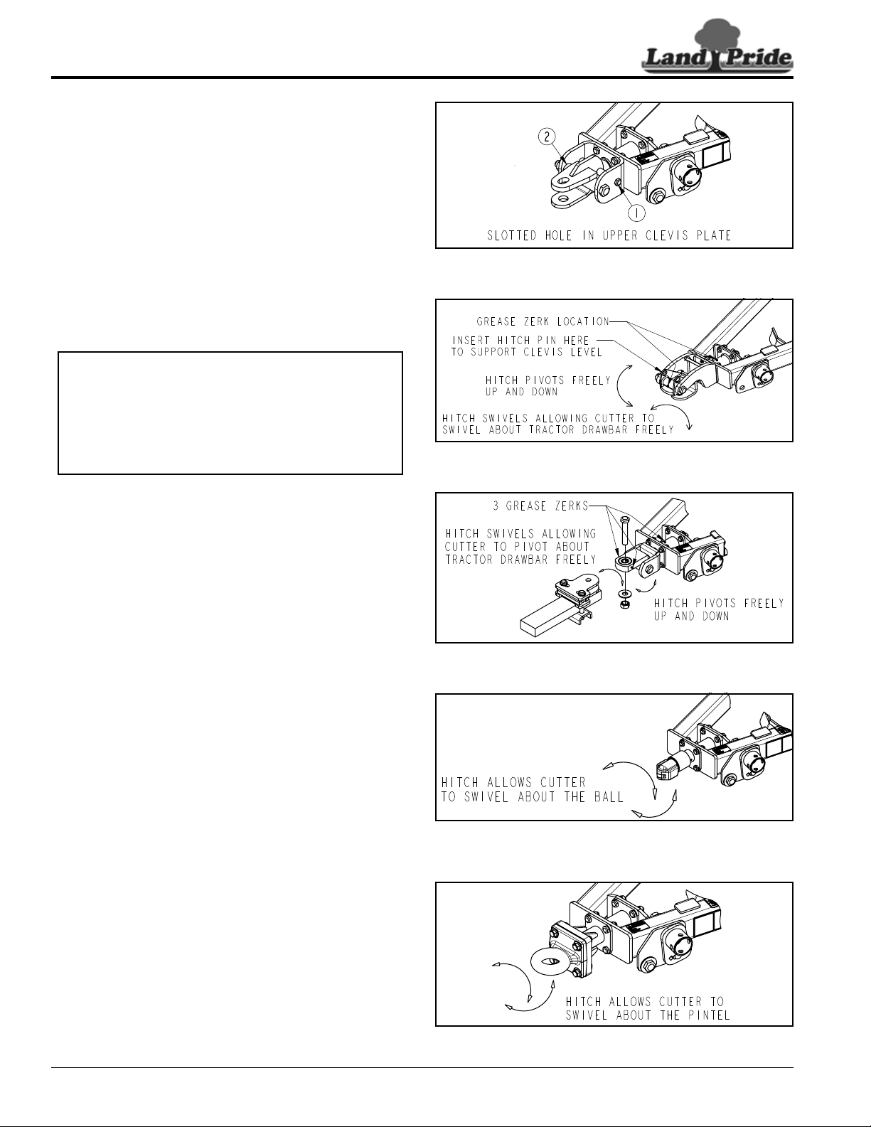
Standard Clevis Hitch
Refer to Figure 1-2:
Cutter rotation about the tractor drawbar is limited to slot
in the upper clevis plate, hole size in the lower clevis
plate, and drawbar hole size. Customer to supply hitch
pin and hitch pin keeper.
Land Pride Performance Hitch (Optional)
Refer to Figure 1-3:
The LP Performance Hitch is a drawbar friendly,
self-leveling hitch that pivots up and down, and side-to-
side. It is held upright with customer supplied hitch pin to
allow single-person hook-up.
Bar-Tite Hitch (Optional)
Refer to Figure 1-4:
The bar-tite hitch functions similar to LP Performance
hitch except it clamps directly to the drawbar. The bar-tite
hitch is sandwiched between hardened steel plates to
eliminate drawbar wear. It has a bushing in the tongue to
extend hitch life. Bushing and hitch swivel are greasable.
Ball Hitch (Optional)
Refer to Figure 1-5:
Cutter rotation about the tractor drawbar is limited to
swivel movement over the 2 5/16" tractor mounted ball.
Pintle Hitch (Optional)
Refer to Figure 1-6:
Cutter rotation about the tractor drawbar is limited to
movement about the pintle connection. The pintle hitch is
ideal for a drawbar hammer strap.
NOTE: The 5/8" bolt (#1) and spacer (#2) may be
removed for more flexibility of hitch. If bolt and
spacer are removed, an equal number of washers
should be added above the drawbar and below the
drawbar to remove gap between drawbar and clevis
hitch. Adding washers when bolt and spacer are
removed will reduce drawbar and hitch wear.
Standard Clevis Hitch
Figure 1-2
LP Performance Hitch
Figure 1-3
Bar-Tite Hitch
Figure 1-4
Ball Hitch
Figure 1-5
Pintle Hitch
Figure 1-6
27928
37590
26599
26600
27928
13
Section 1: Assembly & Set-up
10/21/15
RC4015 and RCM4015 Series 2 S/N 944961+ Rotary Cutters 330-845M
Table of Contents
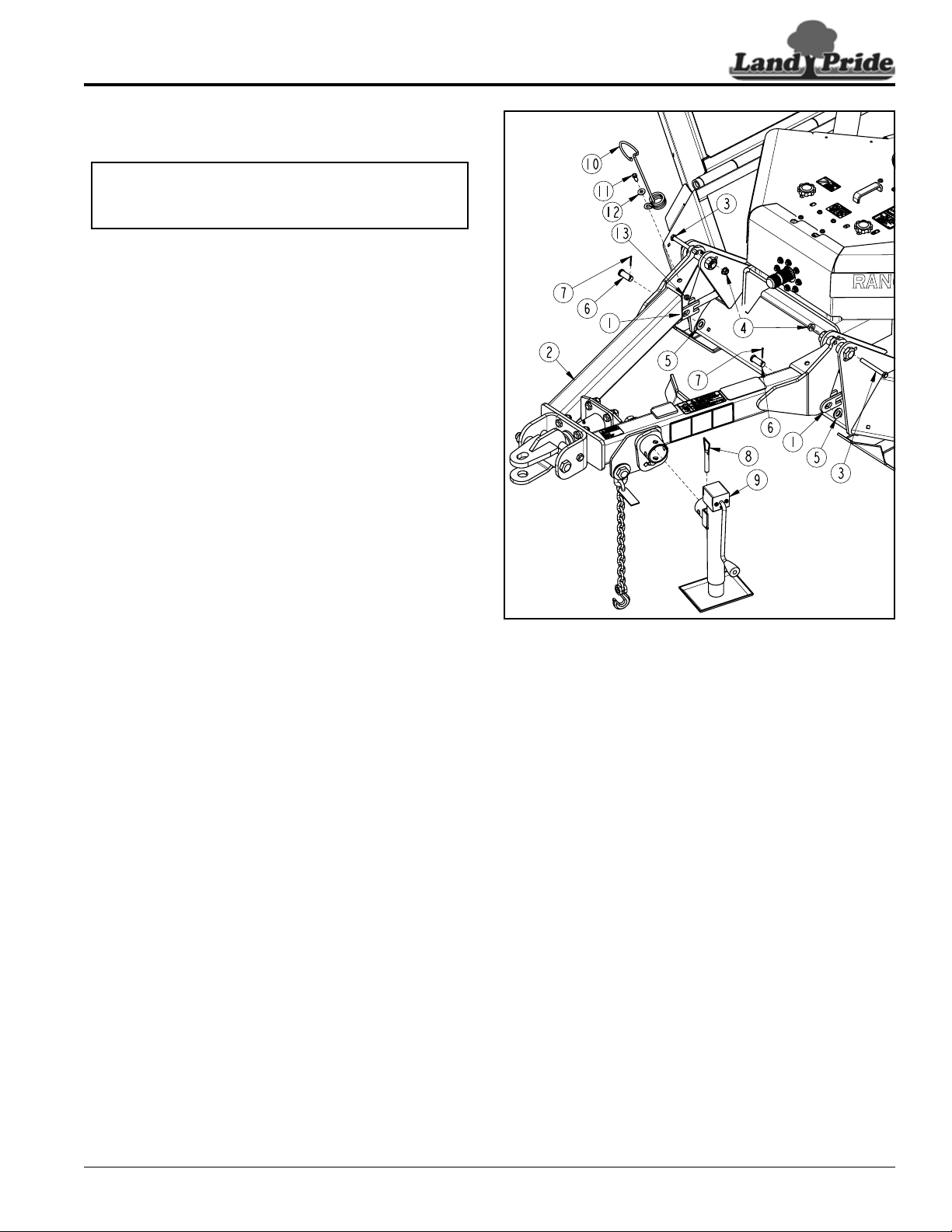
Hitch Assembly
Refer to Figure 1-7:
1. Attach center deck lift cylinder hose to a tractor. See
Hydraulic Hook-up on page 17 for instructions.
2. Raise cutter up with tractor control lever and remove
shipping bracket from center deck cylinder rod.
3. After removal of shipping bracket, lower center deck
completely down until it is resting on its skid shoes.
4. Hitch (#1) is shipped hinged up and bolted in place.
Remove and discard 1/2" hex whiz nuts (#4) and
1/2" bolts (#3).
5. Rotate hitch down into pulling position as shown and
install left and right leveling rods (#1) to hitch
frame (#2) with 3/4" x 1 1/2" clevis pins (#6), 3/4" flat
washers (#5), and 1/8" x 1 1/4" cotter pins (#7).
6. Bend legs of cotter pins to keep pins from falling out.
7. Leveling rod adjustment will be made after cutter is
attached to the tractor.
Park Jack Assembly
Refer to Figure 1-7:
1. Attach park jack (#9) to jack mount and secure with
attached pin (#8).
2. If park jack is not vertical, adjust jack angle according
to “Park Jack Angle Alignment” on page 24.
3. Adjust jack up or down until clevis hitch (#1) is at
drawbar height.
Spring Hose Loop Assembly
Refer to Figure 1-7:
1. Attach spring hose loop (#10) to A-frame hitch (#2)
with 3/8"-16 x 1" GR5 bolt (#11), flat washer (#12),
and hex flange lock nut (#13).
2. Rotate spring hose loop (#10) to face forward as
shown and tighten hex flange lock nut (#13) to the
correct torque.
NOTE: The center deck lift cylinder hose will need
to be attached to a tractor before the hitch on the
cutter can be rotated down for assembly.
Hitch and Jack Assembly
Figure 1-7
Tractor Shutdown Procedure
The following is proper shutdown procedures. Always
follows these procedures before dismounting tractor.
1. If engaged, disengage PTO.
2. Lower attached implement to ground, put tractor in
park or set park brake, turn off engine, and remove
switch key to prevent unauthorized starting.
3. Wait for all components to come to a complete stop
before leaving the operator’s seat.
37591
14
Section 1: Assembly & Set-up
RC4015 and RCM4015 Series 2 S/N 944961+ Rotary Cutters 330-845M
10/21/15
Table of Contents
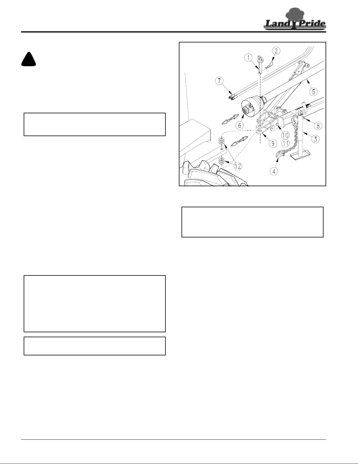
Standard Clevis Hitch Hook-up
!
DANGER
A Crushing Hazard exists when hooking-up equipment to a
tractor. Do not allow anyone to sta nd between tractor and
implement while backing-up to implement. Do not operate
hydraulic 3-Point lift controls while someone is directly
behind the tractor or near the implement.
Refer to Refer to Figure 1-11:
1. Make certain park jack (#3) is properly attached
to the cutter hitch and secured with detent pin (#8). If
park jack is not vertical, refer to “Park Jack Angle
Alignment” on page 24.
2. Store center 3-point link in its storage hook.
3. Start tractor, raise 3-point arms fully up, and carefully
back tractor within close proximity of clevis (#9).
4. Shut tractor down properly before dismounting. Refer
to “Tractor Shutdown Procedure” on this page.
5. Verify tractor drawbar is adjusted correctly. Refer to
“Drawbar Set-up” dimensions on page 11.
6. Raise or lower park jack (#3) to align clevis (#9) with
tractor drawbar. Drawbar should fit between lower
and upper plates of clevis.
7. Restart tractor and continue to back tractor up to
cutter hitch until hole in tractor drawbar and holes in
hitch clevis (#9) are aligned.
8. Shut tractor down properly before dismounting.
9. Customer to supply hitch pin and hairpin cotter.
Insert hitch pin (#1) through top hole in clevis (#9),
tractor drawbar, and out through bottom hole in
clevis. Secure hitch pin with hairpin cotter (#2).
10. Lower park jack (#3) until hitch weight is supported
by drawbar.
IMPORTANT: Ball detent pin (#8) must be fully
inserted in park jack (#3) before working on or
around a cutter not hooked to a tractor drawbar.
The 5/8" bolt (#10) and spacer (#11) may be
removed for more flexibility of hitch. If they are
removed, an equal number of flat washers (#12)
should be added above drawbar and below drawbar
to remove gap between drawbar and clevis hitch.
Adding washers with bolt and spacer removed will
reduce drawbar and hitch ware.
(Flat washers are customer supplied.)
NOTE: Hitch pin (#1) and hairpin cotter (#2) are
supplied by customer.
Tractor Hookup to Standard Clevis Hitch
Figure 1-11
11. Remove park jack (#3) from hitch and attach it to the
left-hand wing storage base with detent pin (#8).
Make sure base is level with or lower than the head
especially after the wings are folded up. See cover
picture for correct positioning.
12. Attach hitch safety chain (#4) to tractor. Adjust chain
length to remove all slack except what is necessary
to permit turning. Lock chain hook securely to the
safety chain.
13. Continue with “Hydraulic Hook-up” on page 17 and
“Driveline Installation” on page 18.
27973
IMPORTANT: Protect park jack by storing it on the
left wing deck before moving the cutter. Make sure
jack is stored with its base level or lower than the
head to prevent water and freeze damage.
15
Section 1: Assembly & Set-up
10/21/15
RC4015 and RCM4015 Series 2 S/N 944961+ Rotary Cutters 330-845M
Table of Contents
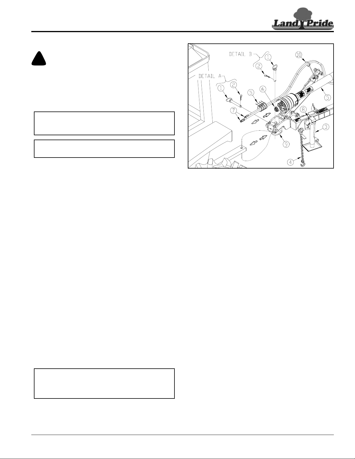
LP Performance Hitch Hook-up
!
DANGER
A Crushing Hazard exists when hooking-up equipment to a
tractor. Do not allow anyone to stand between tractor and
implement while backing-up to implement. Do not operate
hydraulic 3-Point lift controls while someone is directly
behind the tractor or near the implement.
Refer to Figure 1-12:
1. Make certain park jack (#3) is properly attached to
cutter hitch and secured with detent pin (#8). If park
jack is not vertical, refer to “Park Jack Angle
Alignment” on page 24.
2. If clevis (#9) is not already supported horizontal,
rotate clevis horizontal and insert customer-supplied
hitch pin (#1) through horizontal holes in clevis (#9)
as shown in detail A. Secure with hairpin cotter (#2).
3. Store center 3-point link in its storage hook.
4. Start tractor, raise 3-point arms fully up, and carefully
back tractor within close proximity of clevis (#9).
5. Shut tractor down properly before dismounting. Refer
to “Tractor Shutdown Procedure” on page 13.
6. Verify tractor drawbar is adjusted correctly. Refer to
“Drawbar Set-up” dimensions on page 11.
7. Raise or lower park jack (#3) to align clevis (#9) with
tractor drawbar. Drawbar should fit between lower
and upper plates of clevis.
8. Restart tractor and continue to back tractor up to
cutter hitch until hole in tractor drawbar and holes in
hitch clevis (#9) are aligned.
9. Shut tractor down properly before dismounting.
10. Remove hairpin cotter (#2) and hitch pin (#1) from
clevis (#9).
11. Attach cutter to tractor drawbar with hitch pin (#1) and
hairpin cotter (#2) as shown in detail B.
12. Lower park jack (#3) until hitch weight is supported
by tractor drawbar.
13. Remove park jack (#3) from hitch and attach it to the
left-hand wing storage base with detent pin (#8).
Make sure base is level with or lower than the head
especially after the wings are folded up. See cover
picture for correct positioning.
IMPORTANT: Jack detent pin (#8) must be fully
inserted and secured before working on or around a
cutter that is not hooked to the tractor drawbar.
NOTE: Hitch pin (#1) and hairpin cotter (#2) are
customer-supplied.
IMPORTANT: Protect park jack by storing it on the
left wing deck before moving the cutter. Make sure
jack is stored with its base level or lower than the
head to prevent water and freeze damage.
Tractor Hookup to LP Performance Hitch
Figure 1-12
14. Attach hitch safety chain (#4) to the tractor. Adjust
chain length to remove all slack except what is
necessary to permit turning. Lock chain hook
securely to the safety chain.
15. Continue with “Hydraulic Hook-up” on page 17 and
“Driveline Installation” on page 18.
37631
16
Section 1: Assembly & Set-up
RC4015 and RCM4015 Series 2 S/N 944961+ Rotary Cutters 330-845M
10/21/15
Table of Contents
Bar-Tite Hitch Assembly to Tractor Tongue
Figure 1-13
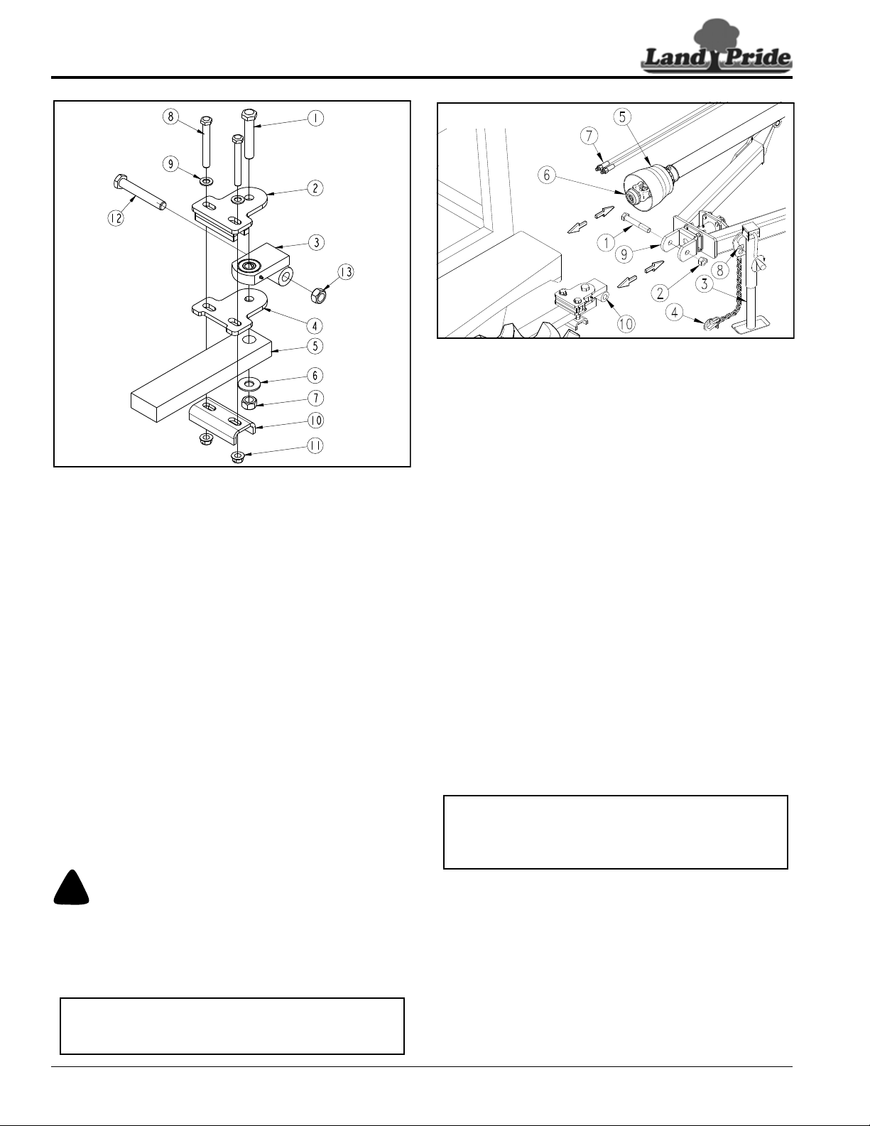
Bar-Tite Hitch Hook-up
Attach Bar-Tite Hitch to Tractor Drawbar
Refer to Figure 1-13:
1. Insert 1" x 5 1/2" hex bolt (#1) through hitch top
plate (#2), hitch bushing (#3), hitch wear plate (#4),
tractor drawbar (#5), and washer (#6) as shown.
Secure with 1" locknut (#7). Tighten 1" locknut snugly
to remove all play and then back nut
one-quarter turn. Do Not torque 1" locknut.
2. Insert two 3/4" x 6" GR5 hex bolts (#8) through,
3/4" flat washers (#9), hitch top plate (#2), hitch wear
plate (#4), and formed hitch support (#10) as shown.
Secure with 3/4" locknuts (#11).
3. Tighten 3/4" locknuts to correct torque.
4. Remove 1" x 6 1/2" GR5 hex bolt (#12) and 1" lock
nut (#13) from hitch bushing (#3). Keep bolt and
locknut for reuse.
Attach Bar-Tite Hitch to Rotary Cutter
Refer to Figure 1-14:
!
DANGER
A Crushing Hazard exists when hooking-up equipment to a
tractor. Do not allow anyone to stand between tractor and
implement while backing-up to implement. Do not operate
hydraulic 3-Point lift controls while someone is directly
behind the tractor or near the implement.
22265
IMPORTANT: Ball detent pin (#8) must be fully
inserted in park jack (#3) before working on or
around a cutter not hooked to a tractor drawbar.
Tractor Hookup to Bar-Tite Hitch
Figure 1-14
1. Make certain park jack (#3) is properly attached to
cutter and secured with detent pin (#8). If park jack is
not vertical, refer to “Park Jack Angle Alignment”
on page 24.
2. Store center 3-point link in its storage hook.
3. Start tractor, raise 3-point arms fully up, and carefully
back tractor within close proximity of clevis (#9).
4. Shut tractor down properly before dismounting. Refer
to “Tractor Shutdown Procedure” on page 13.
5. Verify tractor drawbar is adjusted correctly. Refer to
“Drawbar Set-up” dimensions on page 11.
6. Raise or lower park jack (#3) to align hitch (#10) with
bolt hole in swivel clevis (#9).
7. Restart tractor and back tractor up to swivel
clevis (#9) until hole in hitch bushing (#10) aligns with
holes in swivel clevis (#9).
8. Shut tractor down properly before dismounting.
9. Insert 1" x 6 1/2" GR5 hex bolt (#1) through swivel
clevis (#9) and hitch bushing (#10). Secure hex bolt
with locknut (#2). Tighten locknut snugly to remove
all play. Do Not torque 1" locknut.
10. Lower park jack (#3) until hitch weight is supported
by the drawbar.
11. Remove park jack (#3) from hitch frame and attach it
to the left-hand wing storage base with detent
pin (#8). Make sure base is level with or lower than
the head especially after the wings are folded up.
See cover picture for correct positioning.
12. Attach hitch safety chain (#4) to tractor. Adjust chain
length to remove all slack except what is necessary
to permit turning. Securely lock chain hook to the
safety chain.
13. Continue with “Hydraulic Hook-up” on page 17 and
“Driveline Installation” on page 18.
26604
IMPORTANT: Protect park jack by storing it on the
left wing deck before moving the cutter. Make sure
jack is stored with its base level or lower than the
head to prevent water and freeze damage.
Loading...