


 Loading...
Table of Contents
Primary Seeder
PS25120
ls
313-156M
Operator’s Manual
! |
Read the Operator’s manual entirely. When |
|
you see this symbol, the subsequent |
|
|
instructions and warnings are serious - follow |
||
|
without exception. Your life and the lives of |
|
|
others depend on it! |
|
|
© Copyright 2003 Pr inted |
8/21/06 |
Cover photo may show optional equipment not supplied with standard unit.

Table of Contents
Important Safety Information . . . . . . . . . . .1 Introduction . . . . . . . . . . . . . . . . . . . . . . . .7
Section 1: Assembly and Set-up . . . . . . . .8
Sling Brackets . . . . . . . . . . . . . . . . . . . . . . . . . . . . 8 Three-Point Primary Seeder . . . . . . . . . . . . . . . . . 8 Pull-Type Primary Seeder . . . . . . . . . . . . . . . . . . . 9 Pull-Type Primary Seeder with End Wheels . . . . . 9 Pull-Type Primary Seeder with Front Wheels . . . 11
Section 2: Operating Instructions . . . . . .13
General Description . . . . . . . . . . . . . . . . . . . . . . . 13 Operating Check List . . . . . . . . . . . . . . . . . . . . . . 13 Tractor Requirements . . . . . . . . . . . . . . . . . . . . . 13 Front Wheel Pull-Type . . . . . . . . . . . . . . . . . . 13 Tractor 3-Point Hook-Up . . . . . . . . . . . . . . . . . . . 13 Tractor Drawbar Hook-Up . . . . . . . . . . . . . . . . . . 14 Pull-Type and End Wheel Units . . . . . . . . . . . 14 Front Wheel Units . . . . . . . . . . . . . . . . . . . . . . 14 Tractor Hydraulic Hook-Up . . . . . . . . . . . . . . . . . 15 Bleeding Hydraulic System . . . . . . . . . . . . . . . . . 15 Operating Hydraulic Lift System . . . . . . . . . . . . . 15 Transporting . . . . . . . . . . . . . . . . . . . . . . . . . . . . 15 Pull-Type, Front, or End Wheel Seeders . . . . . 15 Parking . . . . . . . . . . . . . . . . . . . . . . . . . . . . . . . . 16 3-Point Seeders . . . . . . . . . . . . . . . . . . . . . . . 16 Pull-Type, Front or End Wheel Seeders . . . . . 16 Seed Level Indicator . . . . . . . . . . . . . . . . . . . . . . 17 Agitator Attachment (Optional) . . . . . . . . . . . . . . . 17 General Operating Instructions . . . . . . . . . . . . 17
Small Grass Seeds Attachment (Optional) . . . . . . 32 Seed Rate Speed Change . . . . . . . . . . . . . . . . 32 Calibrating & Adjusting Seeding Rate . . . . . . . 32 Small Grass Seeds Attachment Seed Rates . . 33
Small Grass Seeds Attachment Metric Seed Rates 35
Agitator Attachment (Optional) . . . . . . . . . . . . . . . 37 Engaging & Disengaging the Agitator Sprocket 37 Calibrating and Adjusting Seed Rate . . . . . . . . 37 Coil Tines (Optional) . . . . . . . . . . . . . . . . . . . . . . 37 Height Adjustment . . . . . . . . . . . . . . . . . . . . . . 37 Danish Tines (Optional) . . . . . . . . . . . . . . . . . . . . 37 Height Adjustment . . . . . . . . . . . . . . . . . . . . . . 37 Walkboard (Optional) . . . . . . . . . . . . . . . . . . . . . . 38 Adjustment w/ Small Grass Seeds Attach . . . . 38 Adjustment w/o Small Grass Seeds Attach . . . 38
Section 4: Maintenance and Lubrication 39
Maintenance . . . . . . . . . . . . . . . . . . . . . . . . . . . . 39 Storage . . . . . . . . . . . . . . . . . . . . . . . . . . . . . . . . 39 Lubrication . . . . . . . . . . . . . . . . . . . . . . . . . . . . . . 39 Roller Chains . . . . . . . . . . . . . . . . . . . . . . . . . . 39 Wheel Arm Pivot Shafts . . . . . . . . . . . . . . . . . . 40 Wheel Bearings . . . . . . . . . . . . . . . . . . . . . . . . 40 Front and Rear Roller Bearings . . . . . . . . . . . . 40 Feeder Cup Drive Sprocket . . . . . . . . . . . . . . . 40
Drive Sprocket Hanger Bearing
(Small Grass Seeds Attachment) . . . . . . . . . . 41
Feeder Cup Drive Sprocket
(Small Grass Seeds Attachment) . . . . . . . . . . 41 Agitator Lockout (Agitator Attachment) . . . . . . 41
Section 3: Adjustments . . . . . . . . . . . . . . |
18 |
Section 5: Options . . . . . . . . . . . . . . . . . . |
42 |
|
Drive System . . . . . . . . . . . . . . . . . . . . . . . . . . . . |
18 |
Small Seeds Attachment 313-113A |
42 |
|
Roller Packing Wheels |
18 |
|||
Agitator Attachment 313-079A |
42 |
|||
Seed Broadcasting System |
18 |
|||
Coil Tine Track Removers 313-078A |
42 |
|||
Seed Rate Speed Change |
18 |
|||
Danish Tine Track Removers 313-077A |
43 |
|||
15 Bushel Speed Change |
18 |
|||
Walkboard 313-130A |
43 |
|||
30 Bushel Speed Change |
18 |
|||
Section 6: Specifications & Capacities . . |
44 |
|||
Calibrating & Adjusting Seeding Rate . . . . . . . . . |
20 |
Section 7: Features & Benefits |
46 |
|
Seed Rate Charts for Ag Drive |
21 |
|||
|
|
|||
Brome Grass Seed Rate Chart . . . . . . . . . . . . . . |
23 |
Section 8: Troubleshooting . . . . . . . . . . . |
47 |
|
Metric Seed Rate Charts for Ag Drive . . . . . . . . . |
24 |
Section 9: Appendix |
48 |
|
Metric Brome Seed Rate Chart |
26 |
|||
Torque Values Chart |
48 |
|||
Seed Rate Charts for Turf Drive |
27 |
|||
Tire Inflation Chart |
48 |
|||
Metric Seed Rate Charts for Turf Drive |
29 |
|||
Warranty |
49 |
|||
|
|
© Copyright 2006 All rights Reserved
Land Pride provides this publication “as is” without warranty of any kind, either expressed or implied. While every precaution has been taken in the preparation of this manual, Land Pride assumes no responsibility for errors or omissions. Neither is any liability assumed for damages resulting from the use of the information contained herein. Land Pride reserves the right to revise and improve its products as it sees fit. This publication describes the state of this product at the time of its publication, and may not reflect the product in the future.
Land Pride is a registered trademark.
All other brands and product names are trademarks or registered trademarks of their respective holders.
Printed in the United States of America.
PS25120 Primary Seeder 313-156M |
8/21/06 |
Land Pride |
Table of Contents |
Important Safety Information
These are common practices that may or may not be applicable to the products described in this manual.
Safety at All Times
Thoroughly read and understand the instructions given in this manual before operation. Refer to the “Safety Label” section, read all instructions noted on them.
Do not allow anyone to operate this equipment who has not fully read and comprehended this manual and who has not been properly trained in the safe operation of the equipment.
▲Operator should be familiar with all functions of the unit.
▲Operate implement from the driver’s seat only.
▲Make sure all guards and shields are in place and secured before operating the implement.
▲Do not leave tractor or implement unattended with engine running.
▲Dismounting from a moving tractor could cause serious injury or death.
▲Do not stand between the tractor and implement during hitching.
▲Keep hands, feet, and clothing away from power-driven parts.
▲Wear snug fitting clothing to avoid entanglement with moving parts.
▲Watch out for wires, trees, etc., when raising implement. Make sure all persons are clear of working area.
▲Turning tractor too tight may cause implement to ride up on wheels. This could result in injury or equipment damage.
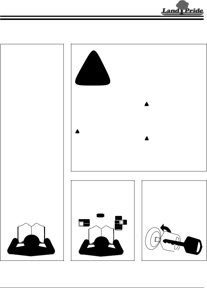
Look For The Safety Alert Symbol
The SAFETY ALERT SYMBOL indicates there is a
!safety precaution must be taken. When you see this symbol, be alert and carefully read the message that follows it. In addition to design and configuration of equipment, hazard control and accident prevention are dependent upon the awareness, concern, prudence and proper training of personnel involved in
the operation, transport, maintenance and storage of equipment.potential hazard to personal safety involved and extra
Be Aware of
Signal Words
A Signal word designates a degree or level of hazard seriousness. The signal words are:
! DANGER
Indicates an imminently hazardous situation which, if not avoided, will result in death or serious injury. This signal word is limited to the most extreme situations, typically for machine components that, for functional purposes, cannot be guarded.
! WARNING
Indicates a potentially hazardous situation which, if not avoided, could result in death or serious injury, and includes hazards that are exposed when guards are removed. It may also be used to alert against unsafe practices.
! CAUTION
Indicates a potentially hazardous situation which, if not avoided, may result in minor or moderate injury. It may also be used to alert against unsafe practices.
For Your Protection
▲Thoroughly read and understand the “Safety Label” section, read all instructions noted on them.
Shutdown and Storage
▲Lower machine to ground, put tractor in park, turn off engine, and remove the key.
▲Detach and store implements in a area where children normally do not play. Secure implement by using blocks and supports.
OFF
REMOVE
8/21/06 |
PS25120 Primary Seeder 313-156M 1 |
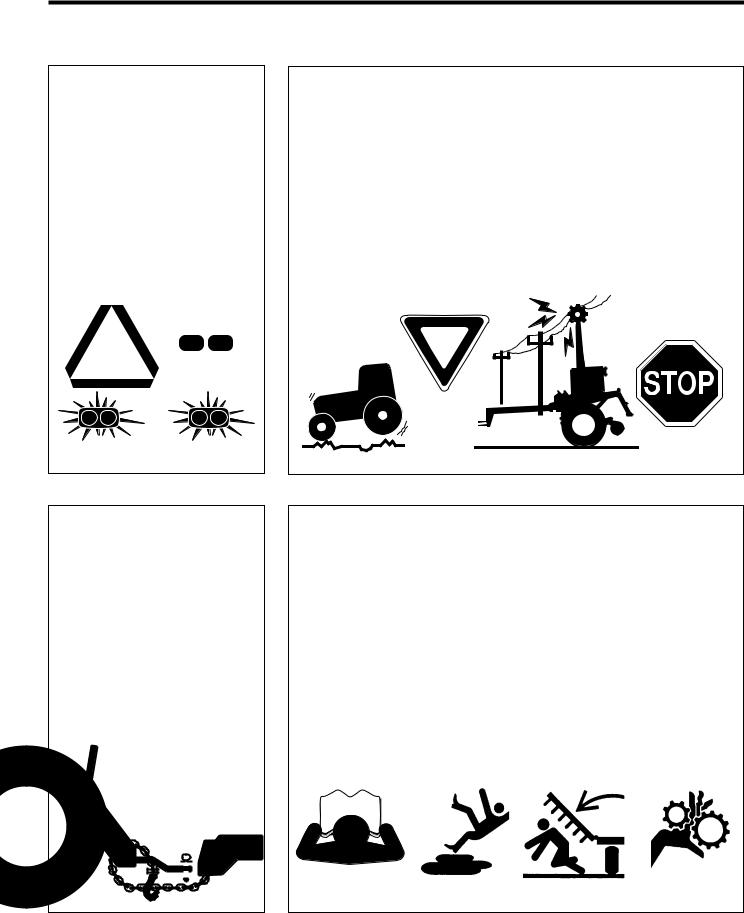
Table of Contents
Important Safety Information
Land Pride
These are common practices that may or may not be applicable to the products described in this manual.
Use Safety
Lights and Devices
▲Slow moving tractors, selfpropelled equipment, and towed implements can create a hazard when driven on public roads. They are difficult to see, especially at night.
▲Flashing warning lights and turn signals are recommended whenever driving on public roads. Use lights and devices provided with implement.
Transport
Machinery Safely
▲Comply with state and local laws.
▲Maximum transport speed for implement is 20 mph. DO NOT EXCEED. Never travel at a speed which does not allow adequate control of steering and stopping. Some rough terrain require a slower speed.
▲Sudden braking can cause a towed load to swerve and upset. Reduce speed if towed load is not equipped with brakes.
▲Use the following maximum speed - tow load weight ratios as a guideline:
20 mph when weight is less than or equal to the weight of tractor.
10 mph when weight is double the weight of tractor.
IMPORTANT: Do not tow a load that is more than double the weight of tractor.
Use A Safety Chain
▲A safety chain will help control drawn machinery should it separate from the tractor drawbar.
▲Use a chain with the strength rating equal to or greater than the gross weight of the towed machinery.
▲Attach the chain to the tractor drawbar support or other specified anchor location. Allow only enough slack in the chain to permit turning.
▲Do not use safety chain for towing.
Practice Safe Maintenance
▲Understand procedure before doing work. Use proper tools and equipment, refer to Operator’s Manual for additional information.
▲Work in a clean dry area.
▲Lower the implement to the ground, put tractor in park, turn off engine, and remove key before performing maintenance.
▲Allow implement to cool completely.
▲Do not grease or oil implement while it is in operation.
▲Inspect all parts. Make sure parts are in good condition & installed properly.
▲Remove buildup of grease, oil or debris.
▲Remove all tools and unused parts from implement before operation.
|
|
|
|
|
|
|
|
|
|
|
|
|
|
|
|
|
|
|
|
|
|
|
|
|
|
|
|
|
|
|
|
|
|
|
|
|
|
|
|
|
|
|
|
|
|
|
|
|
|
|
|
|
|
|
|
|
|
|
|
|
|
|
|
|
|
|
|
|
|
|
|
|
|
|
|
|
|
|
|
2 |
PS25120 Primary Seeder 313-156M |
8/21/06 |
|||||||||||||
Land Pride |
Table of Contents |
Important Safety Information
These are common practices that may or may not be applicable to the products described in this manual.
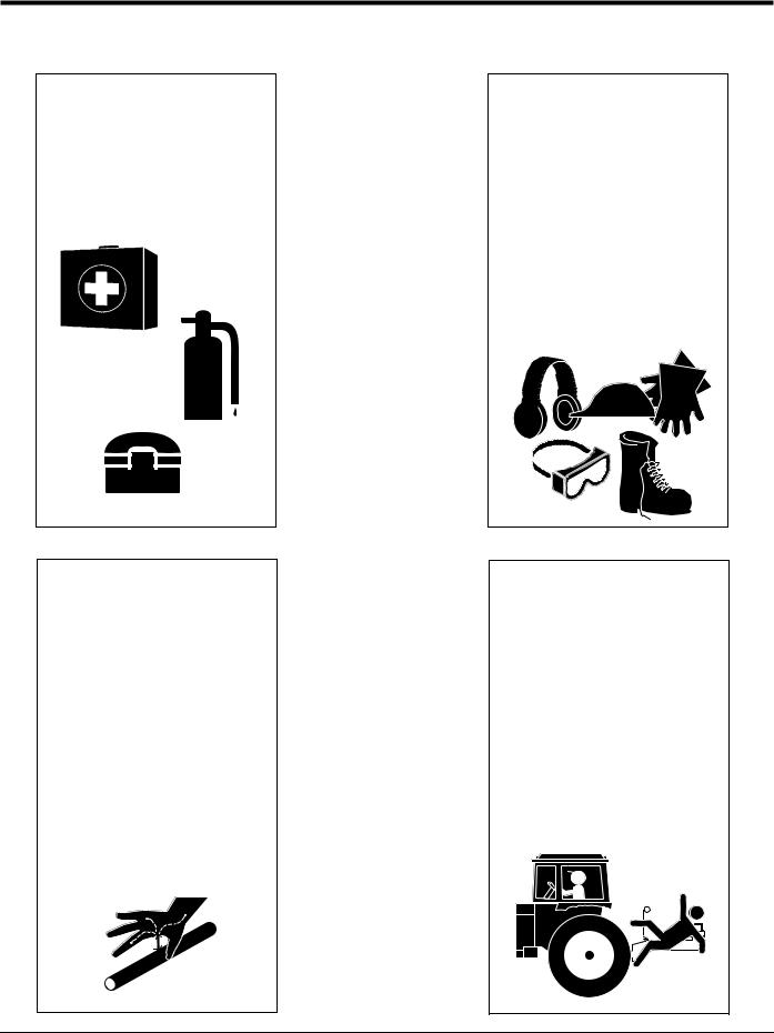
Prepare for Emergencies
▲Be prepared if a fire starts.
▲Keep a first aid kit and fire extinguisher handy.
▲Keep emergency numbers for doctor, ambulance, hospital and fire department near phone.
Wear
Protective Equipment
▲Protective clothing and equipment should be worn.
▲Wear clothing and equipment appropriate for the job. Avoid loose fitting clothing.
▲Prolonged exposure to loud noise can cause hearing impairment or hearing loss. Wear suitable hearing protection such as earmuffs or earplugs.
▲Operating equipment safely requires the full attention of the operator. Avoid wearing radio headphones while operating machinery.
911
Avoid High
Pressure Fluids Hazard
▲Escaping fluid under pressure can penetrate the skin causing serious injury.
▲Avoid the hazard by relieving pressure before disconnecting hydraulic lines.
▲Use a piece of paper or cardboard, NOT BODY PARTS, to check for suspected leaks.
▲Wear protective gloves and safety glasses or goggles when working with hydraulic systems.
▲If an accident occurs, see a doctor immediately. Any fluid injected into the skin must be treated within a few hours or gangrene may result.
Keep Riders
Off Machinery
▲Riders obstruct the operator’s view, they could be struck by foreign objects or thrown from the machine.
▲Never allow children to operate equipment.
8/21/06 |
PS25120 Primary Seeder 313-156M 3 |
Table of Contents
Important Safety Information
Safety Labels
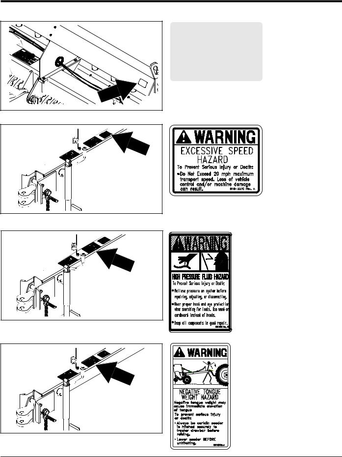
Your Primary Seeder comes equipped with all safety labels in place. They were designed to help you safely operate your implement. Read and follow their directions.
1.Keep all safety labels clean and legible.
2.Replace all damaged or missing labels. To order new labels go to your nearest Land Pride dealer or visit our dealer locator at landpride.com.
3.Some new equipment installed during repair requires safety labels to be affixed to the replaced component as
specified by Land Pride. When ordering new components make sure the correct safety labels are included in the request.
4.Refer to this section for proper label placement. To install new labels:
a.Clean the area the label is to be placed.
b.Spray soapy water on the surface where the label is to be placed.
c.Peel backing from label. Press firmly onto the surface.
d.Squeeze out air bubbles with the edge of a credit card.
818-003C
Slow Moving Vehicle Label
(also found on Small
Seeds Attachment)
12790
818-230C
18938
Red Reflector
|
|
|
|
818-230C |
|
|
|
|
Red Reflector |
|
|
|
12788 |
(also found on Walkboard) |
|
|
|
|
|
4 |
PS25120 Primary Seeder |
313-156M |
|
8/21/06 |
Land Pride |
Table of Contents |
Important Safety Information
|
818-229C |
|
|
Amber Reflector |
|
|
(also found on |
|
12788 |
Walkboard) |
|
12787 |
818-337C |
|
Excessive Speed Hazard |
||
|
||
12787 |
818-339C |
|
|
||
|
High Pressure Fluid |
|
12787 |
|
|
|
818-340C |
|
|
Negative Tongue |
|
|
Weight Hazard |
8/21/06 |
PS25120 Primary Seeder 313-156M 5 |

Table of Contents
Important Safety Information
Land Pride
18938 |
12789 |
12788 |
818-543C Guard Missing
(Beneath Chain Guard)
818-336C |
Caution Cylinder lock
818-338C
Caution General Safety
|
|
|
838-111C |
|
|
|
18938 |
|
|
|
Moving Parts |
6 |
PS25120 Primary Seeder |
313-156M |
8/21/06 |
Land Pride
Introduction
Table of Contents
Land Pride welcomes you to the growing family of new product owners.
This implement has been designed with care and built by skilled workers using quality materials. Proper assembly, maintenance, and safe operating practices will help you get years of satisfactory use from the machine.
Application
The PS25120 Primary Seeder is perfect for wide open landscape seeding, turf farms, brome pastures, highway re-seeding and areas where moguls, undulations or depressions do not exist. The main seedbox, available in 15 and 30 bushel capacities, is equipped with our standard fluted seed cups and agitation to seed most turf type grasses, as well as a variety of other seeds from peas to alfalfa.
It is possible to seed two different types of seeds at different rates by utilizing the optional Small Seeds Box. The Small Seeds Box uses a smaller version of our fluted seed cup for seeds such as alfalfa, clover and many other types of small seeds.
See “Section 6: Specifications & Capacities” on page 44 and “Section 7: Features & Benefits” on page 46 for additional information.
Using This Manual
•This Operator’s Manual is designed to help familiarize you with safety, assembly, operation, adjustments, troubleshooting, and maintenance. Read this manual and follow the recommendations to help ensure safe and efficient operation.
•The information contained within this manual was current at the time of printing. Some parts may change slightly to assure you of the best performance.
•To order a new Operator’s or Parts Manual contact your authorized dealer. Manuals can also be downloaded, free-of-charge from our website at www.landpride.com or printed from the Land Pride Service & Support Center by your dealer.
Owner Assistance
The Warranty Registration card should be filled out by the dealer at the time of purchase. This information is necessary to provide you with quality customer service.
If customer service or repair parts are required contact a Land Pride dealer. A dealer has trained personnel, repair parts and equipment needed to service the seeder.
The parts on your Primary Seeder have been specially designed and should only be replaced with genuine Land Pride parts. Therefore, should your seeder require replacement parts go to your Land Pride Dealer.
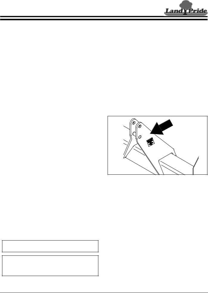
Serial Number Plate
For prompt service always use the serial number and model number when ordering parts from your Land Pride dealer. Be sure to include your serial and model numbers in correspondence also. Refer to Figure 1 for the location of your serial number plate.
15224 |
Serial Number Plate Location
Figure 1
Further Assistance
Your dealer wants you to be satisfied with your new Primary Seeder. If for any reason you do not understand any part of this manual or are not satisfied with the service received, the following actions are suggested:
Terminology
“Right” or “Left” as used in this manual is determined by facing the direction the machine will operate while in use unless otherwise stated.
Definitions
NOTE: A special point of information that the operator must be aware of before continuing.
IMPORTANT: A special point of information related to its preceding topic. Land Pride’s intention is that this information should be read and noted before continuing.
1.Discuss the matter with your dealership service manager making sure he is aware of any problems you may have and that he has had the opportunity to assist you.
2.If you are still not satisfied, seek out the owner or general manager of the dealership, explain the problem and request assistance.
3.For further assistance write to:
Land Pride Service Department
1525 East North Street
P.O. Box 5060
Salina, Ks. 67402-5060
E-mail address lpservicedept@landpride.com
8/21/06 |
PS25120 Primary Seeder 313-156M 7 |
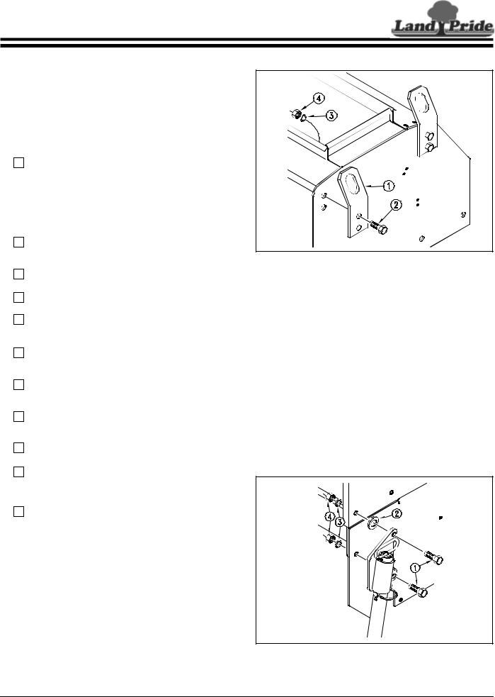
Table of Contents
Section 1: Assembly and Set-up
Before attempting to assemble the seeder use the following as a check list. Having all the needed parts and equipment readily at hand will speed up your assembly task and will make the job as safe as possible.
Pre-Assembly Checklist
|
|
|
Check |
Reference |
|
|
|
Fasteners and pins that were |
Operator’s |
|
|
|
||
|
|
|
shipped with the seeder. |
Manual |
|
|
|
NOTE: All hardware from the |
|
|
|
|
factory has been installed in the |
|
|
|
|
location where it will be used. If a |
|
|
|
|
part or fastener is temporarily |
|
|
|
|
removed for assembly reasons, |
|
|
|
|
remember where it goes. Keep the |
|
|
|
|
parts separated. |
|
|
|
|
|
|
|
|
|
All working parts are moving |
Operator’s |
|
|
|
||
|
|
|
freely, bolts are tight and cotter |
Manual |
|
|
|
||
|
|
|
pins are spread. |
|
|
|
|
|
|
|
|
|
All grease fittings are in place and |
Section 5 |
|
|
|
||
|
|
|
lubricated. |
Page 39 |
|
|
|
||
|
|
|
|
|
|
|
|
Proper tension and alignment on |
Operator’s |
|
|
|
||
|
|
|
all drive chains. |
Manual |
|
|
|
||
|
|
|
|
|
|
|
|
Safety decals are correctly located |
Important |
|
|
|
and legible. Replace if damaged. |
Safety |
|
|
|
||
|
|
|
|
Information |
|
|
|
Red and amber reflectors are |
Important |
|
|
|
||
|
|
|
correctly located and visible. |
Safety |
|
|
|
||
|
|
|
|
Information |
|
|
|
|
|
|
|
|
“Slow moving vehicle” emblem is |
Important |
|
|
|
||
|
|
|
in place. |
Safety |
|
|
|
||
|
|
|
|
Information |
|
|
|
|
|
|
|
|
Inflate tires to specified PSI air |
Section 8 |
|
|
|
||
|
|
|
pressure. Tighten wheel bolts to |
Page 48 |
|
|
|
||
|
|
|
specified torque. |
|
|
|
|
|
|
|
|
|
Have a minimum of 2 people at |
Section 1 |
|
|
|
||
|
|
|
hand while assembling the drill. |
|
|
|
|
|
|
|
|
|
|
|
|
|
|
Have a fork lift or loader along with |
Section 1 |
|
|
|
||
|
|
|
chains and safety stands that are |
|
|
|
|
|
|
|
|
|
sized for the job ready for the |
|
|
|
|
assembly task. |
|
|
|
|
|
|
|
|
|
Have a tractor with remote |
Section 1 |
|
|
|
||
|
|
|
hydraulics ready to attach to the |
Page 15 |
|
|
|
||
|
|
|
tongue. The tongue must be |
|
|
|
|
anchored to a large enough tractor |
|
|
|
|
to overcome the negative tongue |
|
|
|
|
weight that will be present if the |
|
|
|
|
unit is equipped with front wheels. |
|
|
|
|
CAUTION! Be familiar with the |
|
|
|
|
term NEGATIVE TONGUE |
|
|
|
|
WEIGHT. Be aware of the special |
|
|
|
|
precautions you should take when |
|
|
|
|
working with an implement that |
|
|
|
|
can develop Negative Tongue |
|
|
|
|
Weight. |
|
|
|
|
|
|
Sling Brackets
After the unit is uncrated check to see if the sling brackets are installed, if not, install them now - two on each end of unit with hardware, refer to Figure 1-1.
15226 |
Sling Bracket Installation
Figure 1-1
The sling brackets allow points at each end to hook the chain for lifting of the unit. When hooking the chain to sling brackets, be certain to either use a spreader bar on the chain or use a long chain to prevent bending the sling brackets.
Three-Point Primary Seeder
Your 3-Point 25 Series Primary Seeder is shipped to you almost completely assembled. Carefully follow the instructions below for final assembly.
1.Remove the seeder from its crating.
2.Refer to Figure 1-2 for installation of parking stand. To install use the 5/8" x 2 1/4" long bolts (#1), a flat washer (#2), lock washers (#3), and nuts (#4) on the left end of the seeder frame as shown. Be sure to use the flat washer (#2) as shown to ensure proper installation of the parking stand.
15225
Parking Stand Installation
Figure 1-2
8 |
PS25120 Primary Seeder 313-156M |
8/21/06 |
Land Pride |
Table of Contents |
Section 1: Assembly and Set-up
3.Refer to Figure 1-3 for installation of the acremeter on to the right hand drive shaft.
15257 |
Acremeter Installation
Figure 1-3
4.Check to see all nuts are tightened. See Torque Values Chart in “Section 9: Appendix” on page 48 for torque specifications.
Pull-Type Primary Seeder
1.Remove the seeder and components from their crating.
2.Attach the tongue to the seeder with hitch pins (#1). Attach the turnbuckle (#2) to the tongue and the top hitch of the seeder with hitch pins (#3), refer to Figure 1-4.
12736 |
Tongue & Turnbuckle Assembly
Figure 1-4
3.Refer to Figure 1-3 for installation of the acremeter on to the right hand drive shaft.
4.Check to see all nuts are tightened. See Torque Values Chart in “Section 9: Appendix” on page 48 for torque specifications.
Pull-Type Primary Seeder with End Wheels
! WARNING
Serious injury or death could result from escaping high pressure hydraulic fluid. Use paper or cardboard, NOT BODY PARTS, to check for suspected leaks.
1.Remove the seeder and components from their crating.
2.Follow steps 2 and 3 of the “Pull-type Primary Seeder” for assembly of tongue and acremeter.
3.Install spring hose loop (#1) to tongue with 5/16" x 3/4" long bolts (#2), 5/16" lock washer (#3), and 5/16" USS flat washer (#4), Figure 1-5.
12737
Spring Hose Loop Assembly
Figure 1-5
Refer to Figure 1-6:
4.Starting with the left hand side of the seeder, remove the four 5/8" bolts and attach the end wheel mount (#1) to the seeder frame replacing the 5/8" bolts with 5/8" x 2 1/4" long bolts (#2). Flat washers (#3) are used between the end wheel mounts and the seed box for proper spacing.
5.Install the wheel bracket using 3/4" u-bolts (#4), flat washers (#5) and nuts (#6).
NOTE: The wheel bracket (#7) should be facing the rear of the seeder. To determine the correct positioning for the wheel brackets, note the tab (#8) on the end of the wheel arm pivot (#9). This tab should be facing away from the seeder, as shown, so the wheel arm pivot can be easily removed.
8/21/06 |
PS25120 Primary Seeder 313-156M 9 |
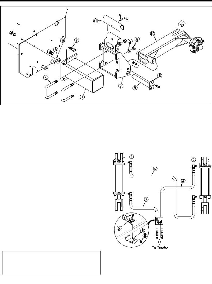
Table of Contents
Section 1: Assembly and Set-up
Land Pride
12738 |
Wheel Bracket & Wheel Arm Assembly
Figure 1-6
6.Remove wheel arm pivot shaft from wheel bracket.
7.Position the wheel arm (#10) so that the wheel points away from the seeder with cylinder bracket up. Replace wheel arm pivot shaft.
8.Pin the cylinder lock (#11) in storage position.
9.Repeat steps 5-9 for the right hand side.
Refer to Figure 1-7:
10.Install 3 1/4” x 8” x 1 1/4” hydraulic cylinder (#1) and 3 1/2” x 8” x 1 1/4” hydraulic cylinder (#2) and complete the plumbing as shown in Figure 1-7. Route the hydraulic hoses (#3) through the spring hose loop and along the tongue, behind the upper hitch and through the holes in the box supports, finishing with the hoses going around the frame end plates and through the hose retainers on the top of the wheel brackets. Route the hydraulic hose (#4) through the holes in the box supports, and finish with the hose going around the frame end plates and through the hose retainers on the top of the wheel brackets. Any excess hose should be coiled and tied with a plastic tie, placing the coil between the upper hitch. Position hose clamp (#5) & (#6) as shown and fasten together with 5/16" long carriage bolt (#7) and 5/16" flange nut (#8). Secure hoses to tongue using one of the plastic cable ties provided.
NOTE: Your End Wheel Seeder is equipped with rephasing hydraulic lift cylinders. The plumbing must be assembled correctly in order for the rephasing cylinders to function properly.
11.Check to see all nuts are tightened. See Torque Values Chart in “Section 9: Appendix” on page 48 for torque specifications.
15258
End Wheel Hydraulic Schematic
Figure 1-7
10 PS25120 Primary Seeder 313-156M |
8/21/06 |
Land Pride |
Table of Contents |
Section 1: Assembly and Set-up
Pull-Type Primary Seeder with Front Wheels
! WARNING
Serious injury or death could result from escaping high pressure hydraulic fluid. Use paper or cardboard, NOT BODY PARTS, to check for suspected leaks.
1.Remove the seeder and components from their crating.
2.Refer to Figure 1-3 on page 8 for installation of the acremeter on to the right hand drive shaft.
3.Install spring hose loop, Figure 1-5 on page 8.
! CAUTION
The Accumulator/Cylinder Package furnished with your front wheel option is provided for your protection. Lack of or improper installation may result in injury or in damage to your seeder because of the negative tongue weight involved with the front wheels.
4.Attach the tongue to the seeder with hitch pins.
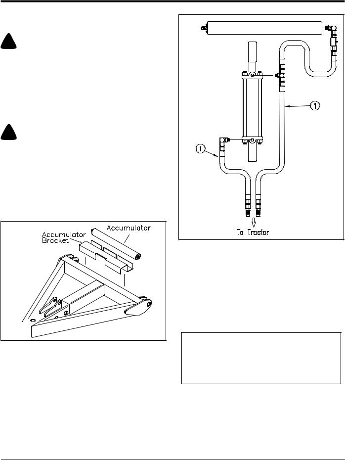
5.Refer to Figure 1-8 and attach the accumulator bracket and accumulator to the rear of the tongue as shown, fastening with hose clamps provided.
12739 |
Accumulator Assembly
Figure 1-8
6.Refer to Figure 1-10 and install hydraulic cylinder with single lug (#1) to tongue and top hitch as shown.
7.Complete the plumbing by following the schematic in Figure 1-9. The plumbing must be assembled correctly in order for the accumulator to function properly. Route the hydraulic hoses (#1) along the tongue. These hoses will be clamped together with the wheel cylinder hoses in step 13.
15501 |
Accumulator Hydraulic Schematic
Figure 1-9
Refer to Figure 1-10:
8.Install the wheel bracket (#2) using 3/4" u-bolts (#3), flat washers (#4) and nuts (#5). The wheel bracket should be facing the front of the seeder. To determine the correct positioning for the wheel brackets, note the tab (#6) on the end of the wheel arm pivot (#7). This tab should be toward the outside of the seeder, as shown, so the wheel arm pivot can be easily removed.
NOTE: The corresponding wheel brackets must be positioned with the 1" hole over the front wheel locating stub (#8) on the frame as shown for proper distribution of seeder weight when in transport. Locating the brackets at any other place on the frame could result in damage to the seeder.
9.Remove wheel arm pivot shaft from wheel bracket.
10.Position the wheel arm (#9) so that the wheel points toward the outside of the seeder with cylinder bracket up. Replace wheel arm pivot shaft.
11.Pin the cylinder lock (#10) in storage position.
12.Repeat steps 9-11 for the right hand side.
8/21/06 |
PS25120 Primary Seeder 313-156M 11 |
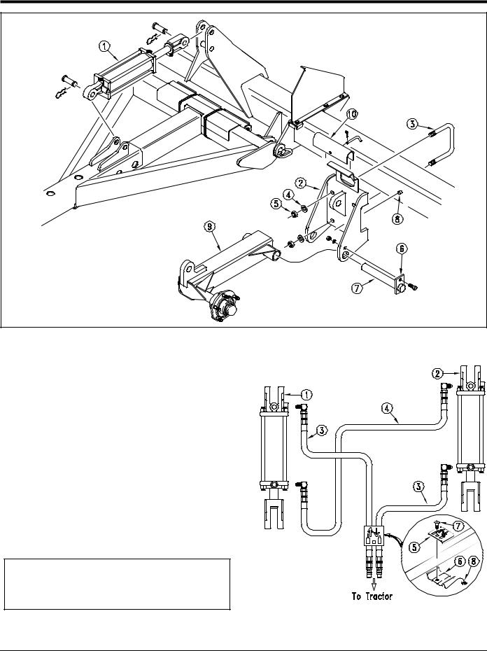
Table of Contents
Section 1: Assembly and Set-up
Land Pride
12740 |
Cylinder, Wheel Bracket & Wheel Arm Assembly
Figure 1-10
Refer to Figure 1-11:
13. Install 3 1/2” x 8” x 1 1/4” hydraulic cylinder (#1) 3 1/ 4” x 8” x 1 1/4” hydraulic cylinder (#2) and complete the plumbing as shown. Route the hydraulic hoses (#3) through the spring hose loop and along the tongue, underneath the turnbuckle, behind the upper hitch and through the holes in the box supports, finishing with the hoses going through the hose retainers on the top of the wheel brackets. Route the hydraulic hose (#4) through the holes in the box supports, and finishing with the hose going through the hose retainers on the wheel brackets. Any excess hose should be coiled and tied with a plastic tie, placing the coil between the upper hitch. Position hose clamp (#5) & (#6) as shown and fasten together with 5/16" x 1 1/4" long carriage bolt (#7) and 5/16" flange nut (#8) adding the hoses from step 7. Secure hoses to tongue using one of the plastic cable ties provided.
NOTE: Your Front Wheel Seeder is equipped with rephasing hydraulic lift cylinders. The plumbing must be assembled correctly in order for the rephasing cylinders to function properly.
15259
14. Check to see all nuts are tightened. See Torque |
Front Wheel Hydraulic Schematic |
|
Values Chart in “Section 9: Appendix” on page 48 |
||
Figure 1-11 |
||
for additional torque specifications. |
||
|
12 PS25120 Primary Seeder 313-156M |
8/21/06 |
Land Pride |
Table of Contents |
Section 2: Operating Instructions
General Description
The following information is a brief description of how this implement works. It is included to help you understand the operation of this seeder.
Adequate front end weight is required on tractors for use with a 3-point seeder. Check tractor’s 3-point lifting capacity. Refer to “Section 6: Specifications & Capacities” on page 44 for seeder weight.
The power to drive the seeding function of this seeder comes from the ground speed of the tractor. The seed metering is powered by the front roller at a rate proportional to the distance driven. This ensures that the rate applied in pounds per acre or pounds per 1000 square feet remains constant as ground speed is varied. The power is transmitted via drive chains to the seed cups. This drive can be adjusted to a high or low range to broadcast more or less seed. The seed rate is adjustable using the seed rate lever located at the rear of the seeder. The seed is dropped between cast iron rollers. The front roller crushes clods, presses down small stones and forms a firm seedbed. The rear roller firms the soil around the seeds.
Operating Check List
In addition to design and configuration of equipment; hazard control and accident prevention are dependent upon the awareness, concern, prudence and proper training involved in its operation, transport, maintenance and storage of equipment. Before beginning to operate your Primary Seeder, the following inspection should be performed.
|
|
Check |
Reference |
|
|
|
|
|
|
Safety Rules |
Page 1 |
|
|
|
|
|
|
|
|
|
|
Operating Instructions |
Page 13 |
|
|
|
|
|
|
Tire Pressure |
Page 48 |
|
|
|
|
|
|
Lubricate seeder as needed. |
Page 39 |
|
|
|
|
|
|
|
|
|
|
Check for loose fasteners |
Page 48 |
|
|
|
|
|
|
Check for hydraulic leaks |
Page 15 |
|
|
|
|
|
|
Inspect the feed cups and seed |
Page 47 |
|
|
||
|
|
tubes for foreign matter. |
|
|
|
|
|
|
|
|
|
|
|
Set speed change sprocket for |
Page 18 |
|
|
||
|
|
drive type desired. |
|
|
|
|
|
|
|
|
|
|
|
Set seed rate. |
Page 20 |
|
|
|
|
Tractor Requirements
Your PS25120 is designed for tractors in the Category 2 class. Horsepower rating of the tractor should not be less than 40 HP for a pull-type unit and not less than 50 HP for 3-Point, front wheel or end wheel units.
NOTE: In order to maintain steering control, balast may have to be added to your tractor. To determine whether or not to add ballast, refer to your tractor operator’s manual.
Front Wheel Pull-Type
With the seeder loaded and raised for transport, certain drawbar capacities could be exceeded by negative tongue weight, see “Tractor Drawbar Hook-Up” on page 14.
Tractor 3-Point Hook-Up
1.Back tractor up to seeder until 3-Point links are aligned with hitch clevises on seeder.
2.Secure the tractor’s 3-Point lower links to the lower hitch clevises using 1 1/8” diameter hitch pins.
3.Secure the tractor’s top center link to the seeder top hitch using a 1” diameter hitch pin.With the seeder resting on level ground, adjust the tractor’s top link until the seeder is level.
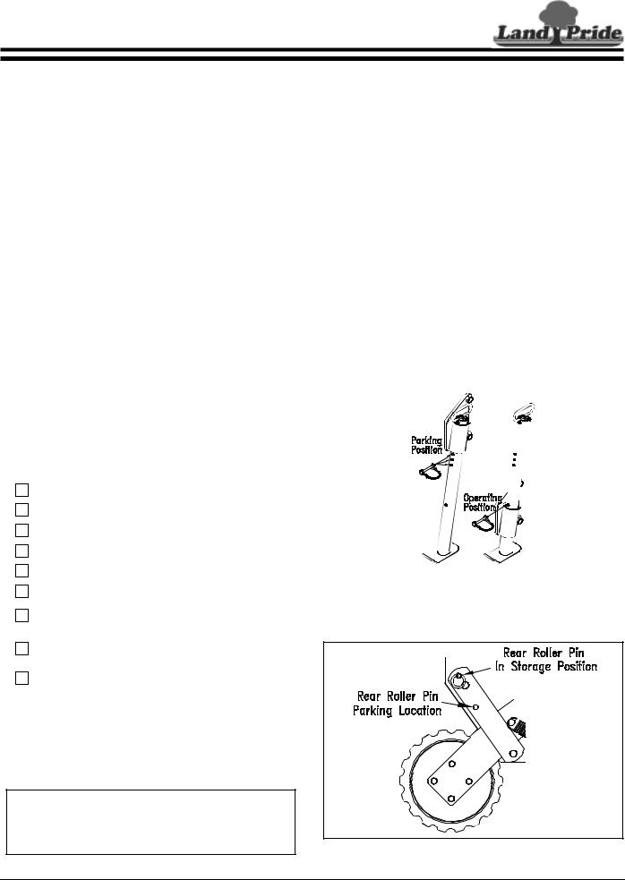
4.Move parking stand to operating position. Refer to Figure 2-1.
15256
Parking Stand Positions
Figure 2-1
5.Remove rear roller lock pin from parking position and place in storage position. Refer to Figure 2-2.
11640
Rear Roller in Storage Position
Figure 2-2
8/21/06 |
PS25120 Primary Seeder 313-156M 13 |
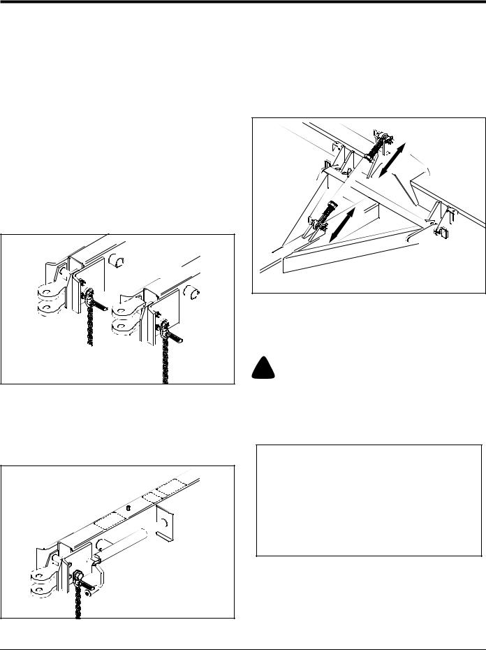
Table of Contents
Section 2: Operating Instructions
Land Pride
Tractor Drawbar Hook-Up
PS25120 pull-type units are equipped with a clevis style hitch. For proper field operation, the seeder box should be level in field position.
1.The mounting holes in the clevis hitch have been offset so the hitch can be turned over and bolted at two different hitch heights, Figure 2-3.
7.All pull-type, end wheel and front wheel units should be properly transported with the seed box level front to back.
Pull-Type and End Wheel Units
Adjust the turnbuckle to level the seeder, Figure 2-5, by loosening the jam nuts and turning center section. Retighten jam nut when level.
2.Back the tractor draw bar up to the seeder hitch to determine the proper hitch position.
3.Connect the hitch to the tractor using a pin of adequate strength (minimum 1” diameter). For the Front Wheel Pull-type option you must install a retaining clip on the hitch pin to prevent it from working up as the seeder changes from positive to negative tongue weight.
4.Your pull-type seeder is equipped with a hitch safety chain. The safety chain should be securely attached to the seeder hitch and tractor draw bar support.
11641
Clevis Style Hitch Height Adjustments
Figure 2-3
5.Retract the jack until the weight of the tongue is resting on the tractor draw bar.
6.Unpin the tongue jack and pin in storage position, Figure 2-4.
11652 |
Turnbuckle Adjustment
Figure 2-5
Front Wheel Units
Use the tongue hydraulic cylinder to level the seed box.
! WARNING
Front wheel pull-type seeders have negative tongue weight when in transport position. Negative tongue weight may cause immediate elevation of tongue. Always be certain seeder is hitched securely to tractor drawbar and safety chain attached before raising. Lower seeder before unhitching.
NOTE: The negative tongue force imposed by the seeder with the front wheel in the raised position when seeder is:
•empty
15 bushel box can be as high as 900 lbs. 30 bushel box can be as high as 1000 lbs.
•loaded
15 bushel box can be as high as 1200 lbs. 30 bushel box can be as high as 1500 lbs.
11654
Jack in Storage Position
Figure 2-4
14 PS25120 Primary Seeder 313-156M |
8/21/06 |
Loading...